

Page 1
T
ECHNICAL INFORMATION
Models No.
LH1040, LH1040F
PRODUCT
P 1 / 20
Description
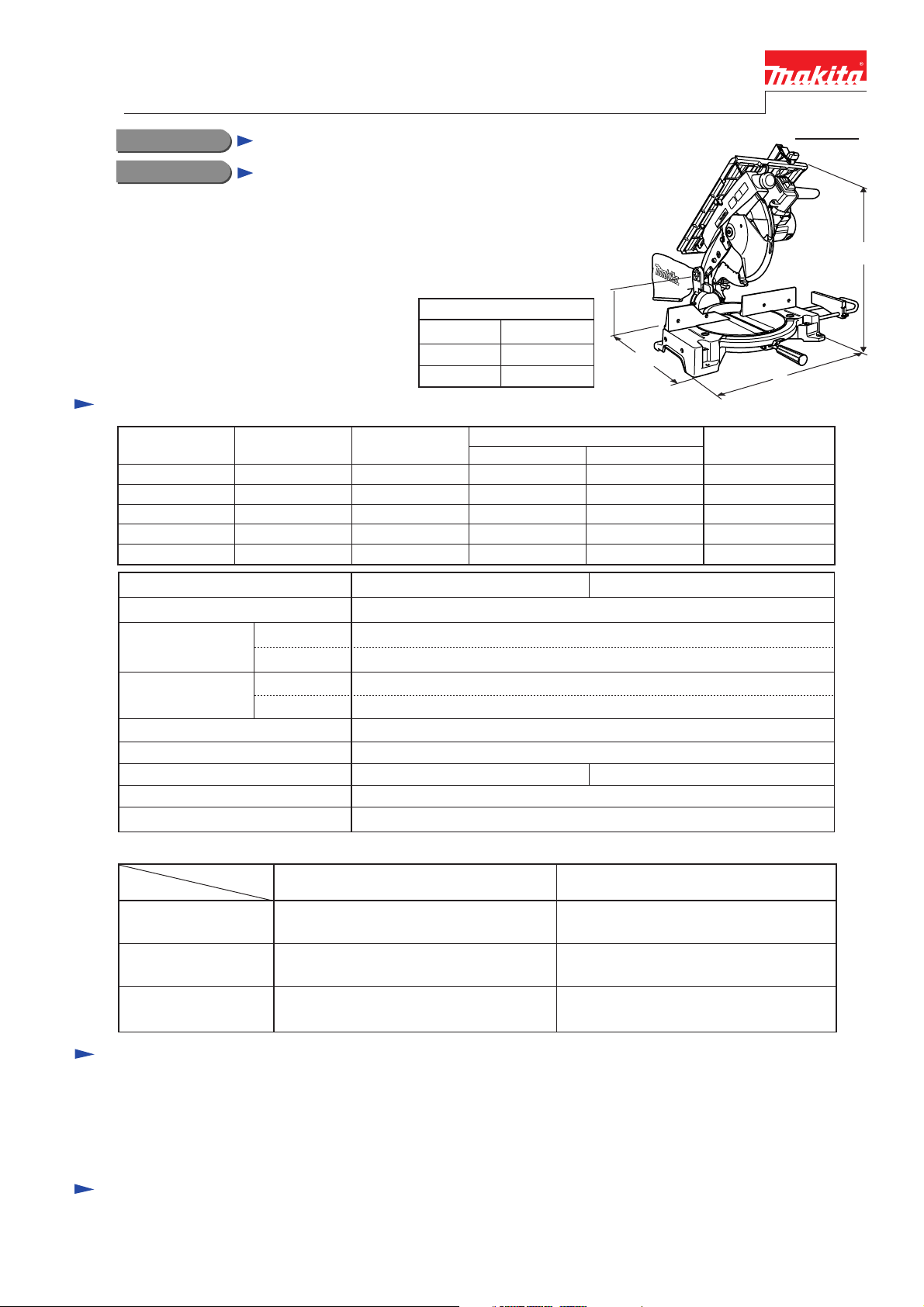
Table Top Miter Saw 260mm (10-1/4")
CONCEPT AND MAIN APPLICATIONS
Models LH1040 and LH1040F have been
developed as multi-purpose miter saws.
Installation of a table on Model LS1040
has enabled miter saw and table saw to be
packed in one tool for great versatility.
LH1040F features LED built-in job light
for accurate tracing of ink line in dark places.
Specification
Voltage (V) Cycle (Hz)
110 15 1,650
120
220
230
240
Model No.
No load speed: min-1 = rpm.
Saw blade: mm (")
Capacity: mm (")
(with 260 mm saw)
Protection against electric shock
Electric brake
LED job light
Cord length: m (ft)
Net weight: kg (lbs)
Current (A)
15 2,30050 / 60
7.9 1,650 1,000 2,30050 / 60
7.5 1,650 1,000
7.2 1,650 1,000 2,30050 / 60
Diameter
Hole diameter
Table saw
Miter saw
Dimensions: mm (")
Length (L)
Width (W)
Height (H)
LH1040
15.88 (5/8) 30.0 ( for European countries)
No Yes
530 (20-7/8)
476 (18-3/4)
535 (21)
Continuous Rating (W)
Input Output
1,650
4,800
255 - 260 (10 - 10-1/4 )
40 (1-9/16 )
See the table below.
Double insulation
Yes
2.5 ( 8.2 )
13.7 (30.2 )
L
1,000
1,000
H
W
Max. Output(W)
2,30050 / 60
2,30050 / 60
LH1040F
Cutting capacity as Miter Saw
Miter angle
45
45
° Right
Bevel angle
90
°
° Left
69mm x 130mm (2-3/4" x 5-1/8")
93mm x 95mm (3-5/8" x 3-3/4")
69mm x 85mm (2-3/4" x 3-3/8")
93mm x 67mm (3-5/8" x 2-5/8")
69mm x 85mm (2-3/4" x 3-3/8")
93mm x 67mm (3-5/8" x 2-5/8")
90°
Standard equipment
TCT saw blade 260mm .......... 1 pc
Dust bag ................................. 1 pc
Holder set ............................... 1 pc
Sub plate ass'y ........................ 1 pc
Note: The standard equipment listed above may differ from country to country.
Socket wrench 13 ....................... 1 pc
Ring 16 (adaptor for saw blades
with 25mm hole diameter) ......... 1 pc
Triangular rule ............................ 1 pc
Optional accessories
Vertical vise
Horizontal vise
Holder set
Assorted TCT saw blades
45
° Left bevel
35mm x 130mm (1-3/8" x 5-1/8")
53mm x 95mm (2-1/16" x 3-3/4")
35mm x 65mm (1-3/8" x 2-9/16")
49mm x 42mm (1-15/16" x 1-5/8")
35mm x 91mm (1-3/8" x 3-5/8")
49mm x 67mm (1-15/16" x 2-5/8")
Set plate ................................... 1 pc
Blade cover .............................. 1 pc
Push stick ................................. 1 pc
Guide rule rule ........................ 1 pc
Page 2
P 2 / 20
Repair
CAUTION: For your safety, before maintenance or repair, be sure to;
1. Disconnect the machine from the power source.
2. Remove the saw blade from the machine.
[1] NECESSARY REPAIRING TOOLS
Tool No./ Description Use for
1R035/ Bearing Setting Plate 15.2 Press-fitting Ball bearings
1R045/ Gear Extractor (large) Disassembling Gear housing cover and Bearing box
1R208/ 90 Degrees Set Square Squaring Saw blade with Base
1R229/ 1/4" Hex shank bit for M5 Removal/Installation of screws that fasten Bearing box
1R235/ Round Bar for Arbor 6-100* (2 pcs) Disassembling Blade case
1R269/ Bearing Extractor Removing Ball bearings
1R291/ Retaining Ring S and R Pliers Removal/Installation of the Retaining ring
1R306/ Ring Spring Removing Jig** Disassembling Blade case
1R340/ Wrench for Bearing Retainer
*Note: Disassembling can be done also using two Phillips screwdrivers of 6.5X100mm or larger size instead.
**Note: Disassembling can be done also using 1R201/ Jig for Retaining Ring.
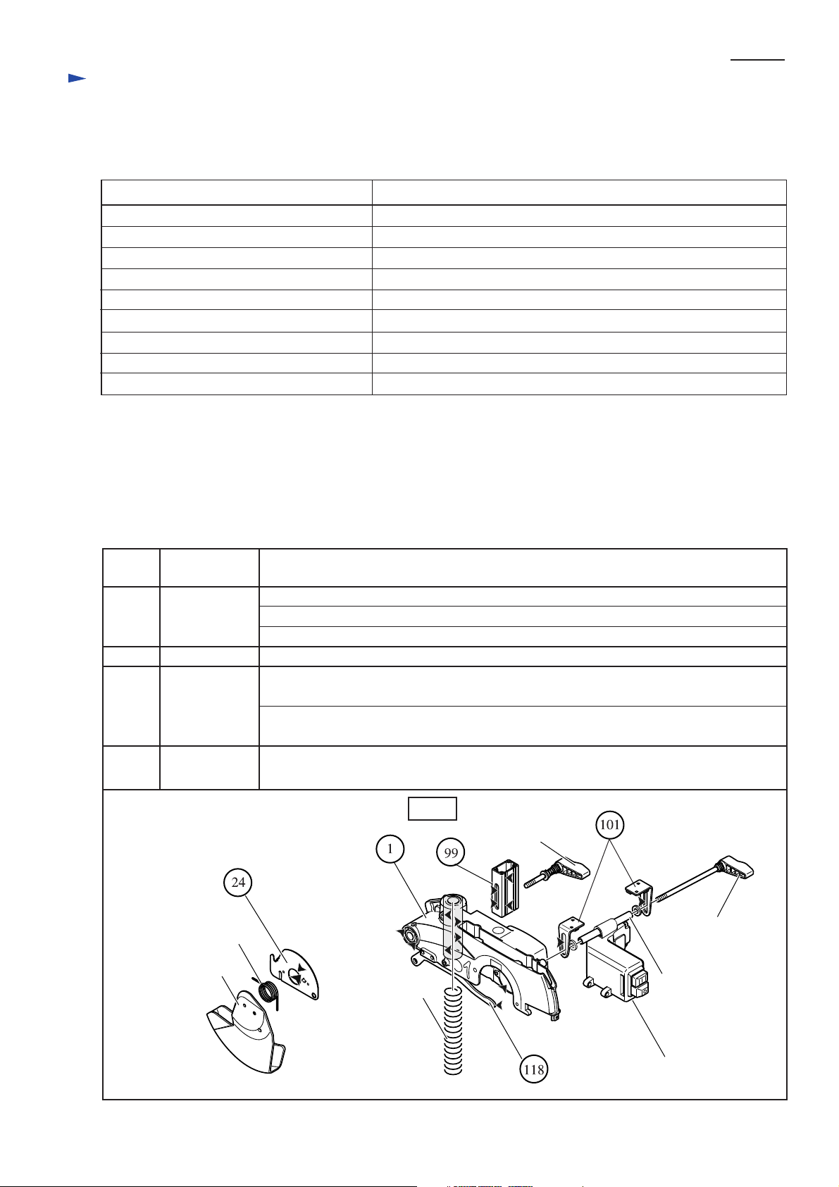
[2] LUBRICATION
1) Apply 12g of Makita grease N No.1 to the gear portion.
2) Apply an appropriate amount of Makita grease N No.1 to each of the listed below.
Although these slide surfaces are factory-greased with Makita grease N No.1, you apply other type of grease such as
Makita grease N No.2 or the like.
Removal/Installation of Bearing retainer
Position
No. Parts item Portion to be lubricated
Gear portion
1
101
Safety cover
Blade case
Center cover24
Table support99
Support plate
Torsion
spring 36
Accepting hole for compression spring 27
The pivotal portion where arm contacts
The portion where torsion spring 36 contacts
The elliptic punched hole where lever 54 contacts, when table support
is slidden up and down.
The side where (1) Blade Case contacts, when table support
is slidden up and down.
The elliptic punched hole where pipe 9-126 contacts, when support plates
are slidden up and down.
Fig.1-1
Compression
spring 27
The appropriate amount is 12g.
Lever 54
Lever 54
Pipe 9-126
Switch box
Page 3
Repair
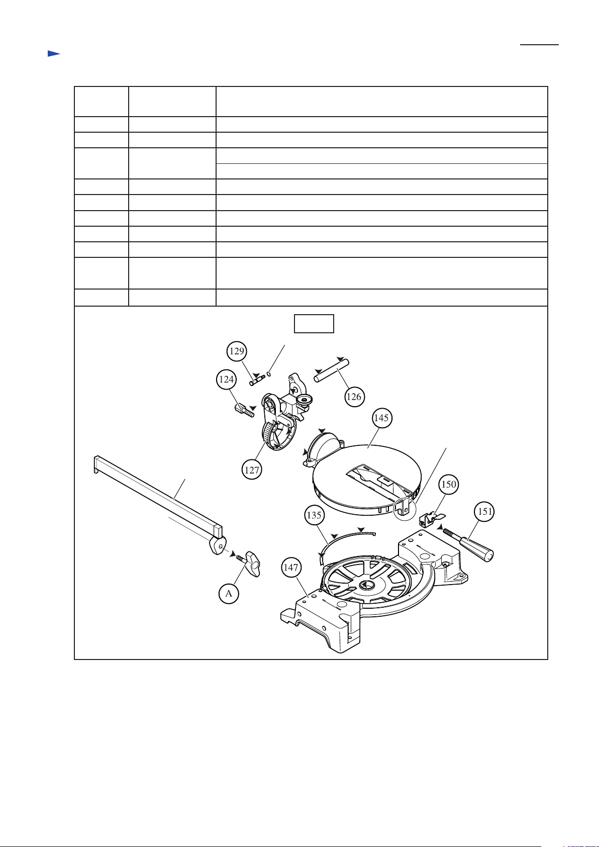
[2] LUBRICATION
Position
No.
124
126
127
Parts item
Hex bolt M10 Threaded portion
Rod 16 The surface where (127) Arm Complete contacts.
Arm complete
Stopper pin129
Slide plate135
Turn base145
Base complete147
Knock spring150
P 3 / 20
Portion to be lubricated
The portion where (145) turn base contacts, when arm complete pivoting.
Accepting portion for pivoting (1) Blade Case
The groove to which O ring 5 is mounted.
The surface where (145) turn base contacts
Accepting portion for pivoting (127) Arm Complete
Accepting boss for the shaft of (145) Turn Base
Both edge which contacts its accepting portion of (145) Turn Base
151
A Tip of the threaded portion
Grip 32
Thumb screw
Tip of the threaded portion with which (150) Knock spring is pushed toward
(145) Turn Base
Fig.1-2
O ring 5
Rip fence
Accepting portion
for (150) Knock Spring
Page 4

Repair
< 3 > Removing table
1. Lift up table by loosening two 54 levers which are equipped under the table. See Fig.2-1.
2. Lift up the table to the highest level. See Fig.2-1.
3. Remove pan head screw M5x16 and remove cover complete from riving knife. See Fig.2-2.
4. Remove 8 M5x16 countersunk head screws. Then, table can be removed from blade case. See Fig.2-2.
And remove compression spring 27 from blade case. See Fig.2-2.
(In case of model LH1040 without fluorescent job light)
4A. While lifting up the table, remove light circuit from the table. Then, table can be removed from blade case.
And remove compression spring 27 from blade case. See Fig.2-2.
(In case of model LH1040F with fluorescent job light)
Fig.2-1
Table
Lever 54
P 4 / 20
Fig.2-2
Pan head
screw M5x16
Riving knife
Hex lock nut M5-8
Cover complete
Countersunk head
screw M5x16 (8 pcs.)
Table
Compression
spring 21
< 4 > Mounting table
1. Secure table with 8 M5x16 countersunk head screws. Refer to Fig.2-2.
2. While lifting up table to the highest level, mount compression spring 21 by inserting it from the side.
3. Take the left step with referring to the above Figs.
Table
Page 5
Repair
< 5 > Removing blade case section
1. Remove living knife. See Fig.3-1.
2. Remove lever 54, support plate and pipe 9-126. See Fig.3-1.
The pipe 9-126 removed in this step, is used as a jig for removing rod 16 which functions as a pivot for blade case.
3. Loosen lever 54 and press table support down to the surface of blade case. See Fig.3-2.
Fig.3-1 Fig.3-2
P 5 / 20
Hex flange
head bolt M8x20
Rod 16
4. Remove two M5x16 pan head screws. Now guard with guard holder can be removed from blade case. See Fig.3-3.
5. Remove hex socket button head screw M6 (adhesive type), flat washer 7 and ring 7. Now the linkage of link plate with
arm complete has been disconnected. See Fig.3-4.
6. Remove stop ring E-5, flat washer 6 and ring 6. then, link plate can be removed from blade case. See Fig.3-5.
Living knife
Table support
Support plate
Pipe 9-126
Fig.3-3
Table support
Lever 54
Lever 54
Fig.3-4
Blade case
Guard holder
Guard
Pan head
screw M5x16
Fig.3-5
Arm complete
Link plate
Ring 7
Flat washer 7
Blade case
Hex socket button
head screw M6
Ring 6
Flat washer 6
Stop ring E-5
Link plate
Page 6
Repair
< 5 > Removing blade case section
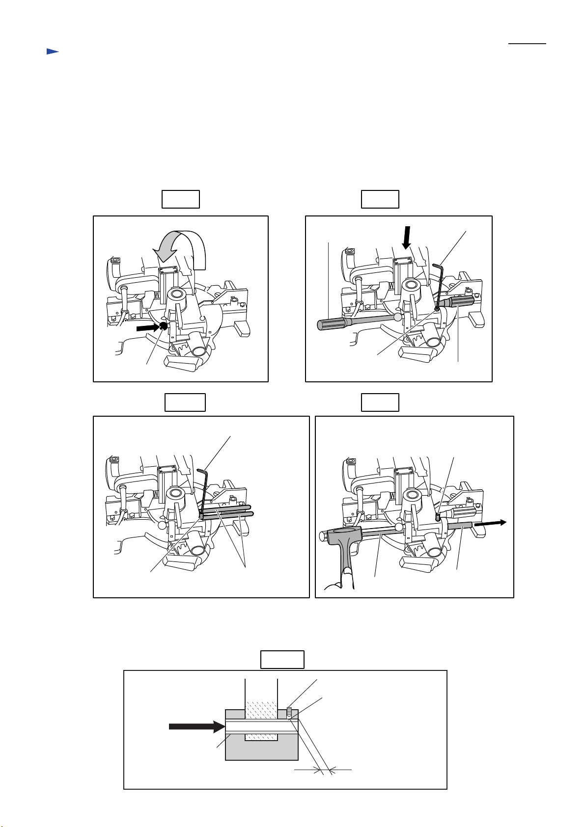
7. Lower the blade case section to the possible lowest position, and lock it at the same position with stopper pin.
See Fig.3-6.
8. While further pressing the blade case section, insert two screwdrivers into the side hole of blade case.
See Fig.3-7. Or insert No.1R238 "Round Bar for Arbor" as illustrated in Fig.3-7A.
9. Loosen hex socket head bolt M6x10 with hex wrench. See Fig.3-7.
10. Apply pipe 9-126 on rod 16, and remove it by striking the pipe with plastic hammer toward the side of hex
socket head bolt M6x10. See Fig.3-8. Now blade case section can be separated from arm complete.
P 6 / 20
Stopper pin
Fig.3-6
Fig.3-7A
Hex wrench
Screwdriver
Hex socket
head bolt M6x10
Fig.3-7
Hex wrench
Screwdriver
Fig.3-8
Hex socket
head bolt M6x10
Hex socket
head bolt M6x10
<Note>
In order to minimize scratch on the accepting holes for rod 16, remove it toward
the side of hex socket head bolt M6x10. See Fig.3-8A.
Direction for
removing rod 16
Rod 16
The scratch on the accepting holes
is minimized to this area.
No.1R238
Round Bar for Arbor
Fig.3-8A
Blade
case
Arm complete
Pipe 9-126
Hex socket head bolt M6x10
The portion scratched with
hex socket head bolt M6x10
Rod 16
Page 7

Repair
< 5 > Removing blade case section
11. Put the removed blade case section on the turn base of arbor press, And set 1R306 "Ring Spring Removing Jig"
between the two screwdrivers, inserted in the step of Fig.3-7. See Fig.3-9.
12. Press down 1R306 "Ring Spring Removing Jig" with arbor press. So, spring holder is pressed down and
the screwdrivers can be pulled out from blade case.
Fig.3-9
P 7 / 20
No.1R306
Ring Spring Removing Jig
13. Put the removed blade case section on the turn base of arbor press, And set 1R306 "Ring Spring Removing Jig"
between the two screwdrivers, inserted in the step of Fig.3-7. See Fig.3-9.
14. Press down 1R306 "Ring Spring Removing Jig" with arbor press in order to lower spring holder,
while holding the blade case section firmly, so that it does not tilt or wobble.
15. Slowly lessen the pressure to 1R306 "Ring Spring Removing Jig", while holding the blade case section
firmly, so that it does not tilt or wobble. See Fig.3-10.
16. Remove spring holder and compression spring 27 from blade case, when the jig gets free from the force
of compression spring. See Fig.3-10.
Fig.3-10
Arbor press
Screwdriver
Blade case section
No.1R306
Ring Spring
Removing Jig
Slowly lessen the
pressure to the jig.
Spring holder
Compression spring 27
Blade case section
Page 8

Repair
< 5 > Mounting blade case section
1. Take the reverse step of removing, while paying attention to the following matters.
A. Scrape off the scratched portion of rod 16 with file, before mounting.
Mount rod 16 from the side of hex socket head bolt M6x10 . See Fig.4-1.
B. When pulling out two screwdrivers in the final step, press the blade case section down to the possible
lowest position. Then, at the same time, spring holder is mounted to the original position automatically.
C. Apply the adhesive to hex socket button head screw M6 with which link plate is secured to arm complete.
Refer to Fig.3-4.
Fig.4-1
P 8 / 20
Hex socket
head bolt M6x10
Blade
case
Arm complete
Direction for
mounting rod 16
Rod 16
The portion scratched with
hex socket head bolt M6x10,
has to be scraped off, before
mounting.
< 6 > Disassembling safety cover section
1. Loosen hex flange head bolt M8x12. Remove socket head flange screw M6 with hex wrench, inserted through
the punched hole of safety cover. Now safety cover section can be separated from blade case. See Fig.5-1.
2. The safety cover section can be disassembled by unscrewing pan head screw M5x12. See Fig.5-2.
Fig.5-1 Fig.5-2
Blade case section
Socket head
flange screw M6
Flat washer 5
Pan head
screw M5x12
Center cover
Center plate
Torsion spring 36
Safety cover
Hex flange head
bolt M8x12
Safety cover
Hex wrench
Tapping screw
bind PT3x8
No need to remove socket head flange screw M6
from center cover, for easy reassembling.
< 7 > Assembling safety cover section
1. In case of the disassembling as illustrated in Fig.5-2, tapping screw bind PT3x8 has to be
removed from safety cover before reassembling.
2. Drive tapping screw bind PT3x8 again, after mounting torsion spring 36, center cover and center plate.
Refer to Fig.5-2.
Page 9

Repair
< 8 > Disassembling motor section
1. Remove carbon brush. See FIg.6-1.
And then, remove table from blade case section as illustrated in Fig.2-1 and Fig.2-2.
2. Remove lever 54 and support plate. See Fig.6-2.
3. After removing four M6x60 pan head screws, motor section can be separated from blade case. See Fig.6-3.
<Note>
Compression spring 9 for shaft lock falls off easily from the machine, when separating motor section
from blade case. Be careful, not to lose this spring.
P 9 / 20
Carbon brush
Brush holder cap
Fig.6-1
Shaft lock
Brush
holder cap
Carbon brush
Fig.6-2
Support plate
Lver 54
Fig.6-3
Pan head screw M6x60
Pan head
screw M6x60
Compression spring 9
< 9 > Assembling motor section
1. Putting shaft lock into the notch of motor housing, mount armature to motor housing. See Fig.7-1.
2. While pushing shaft lock to the direction designated with black arrow, mount the motor section
to blade case in order to avoide piching of shaft lock between motor housing and blade case. See Fig.7-2.
3. Take the reverse step of disassembling after the above process.
Fig.7-1 Fig.7-2
Notch for shaft lock slide
Armature
Shaft lock
Shaft lock
Compression spring 9
Page 10

Repair
< 10> Disassembling safety block mechanism
1. Lock the blade case section at the possible highest position, with stopper pin.
2. Remove lock lever by unscrewing 2 M4x10 pan head screws. Then, lock lever can be removed from lock pin.
See Fig.8-1.
3. Remove motor section as shown in <8> Disassembling motor section, when removing lock pin 8. See Fig.8-2.
P 10 / 20
Pan head screw M4x10
Fig.8-1
Lock pin 8
Lock pin 8
Lock lever
Fig.8-2
Torsion spring 9
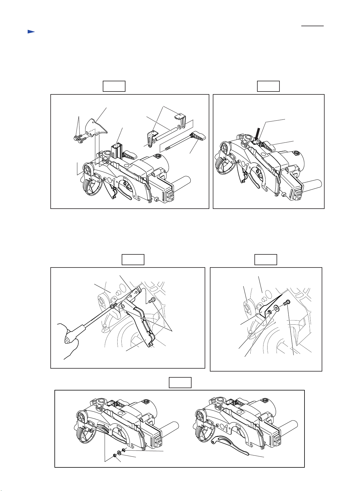
<11> Assembling safety block mechanism
1. Pass lock pin 8 through torsion spring 9, and hold its tail with switch box. See Fig.9-1.
2. While sliding lock lever to switch button side, tighten lock lever with one M4x10 pan head screw preliminarily.
See Fig.9-2.
3. Nip the hooked tail of torsion spring 9 and put it on lock lever. See Fig.9-3.
Lock pin 8
Hold this side
with switch box.
Torsion spring 9
Fig.9-1
Switch box
Torsion spring 9
Lock pin 8
Lock lever
Switch box
Slide lock lever to
switch button side,
when preliminary
tightening.
Fig.9-3
Switch box
Fig.9-2
Switch box
Switch button
Preliminary tightening
with one M4x10 pan
head screw
Hooked tail of torsion
spring 9, put on lock lever
Page 11

Repair
<11> Assembling safety block mechanism
4. Adjust the position of lock lever so that the distance between lock lever and safety cover is approx. 1mm.
See Fig.9-4. And then, finally tighten lock lever with 2 Mx10 pan head screws.
Fig.9-4
Lock lever
Safety cover
Approx. 1mm
P 11 / 20
<12> Removing turn base
1. Remove grip 32. From the bottom side of base, unscrew pan head screw M5x12. Now knock spring can be removed.
See Fig.10-1.
2. After removing guide fence, lever up kerf board with screwdriver to remove them. See Fig.10-2.
3. Remove hex lock nut M8x13 and flat washer 8. Now turn base can be removed from base. See Fig.10-3.
Fig.10-1 Fig.10-2
Hex bolt M8x30
Guide fence
Hex bolt M8x30
Kerf board
Turn base
Pan head screw M5x12
Grip 32
Knock spring
Screwdriver
Page 12

Repair
<12> Removing turn base
3. Remove hex lock nut M8x13 and flat washer 8. Now turn base can be removed from base. See Fig.10-3.
Fig.10-3
Hex lock nut M8x13
Socket wrench 13
which comes
with the product.
Turn base
Flat washer 8
Base
P 12 / 20
<13> Mounting turn base
1. Mount turn base and flat washer 8, and tighten hex lock nut M8x13 with socket wrench 13.
The hex lock nut M8x13 has to be so tightened, that turn base can move without wobbling.
2 Take the reverse step of disassembling after the above process.
<14> Angle adjustment of saw blade
1. Adjusting to 90° to turn base,
While applying 1R208 "90-degree Set Square", turn Hex bolt M8x28 of motor housing side,
until both saw blade and turn base contact the jig closely. See Fig.11-1.
2. Adjusting to 45° to turn base,
While applying 1R207 "45-degree Set Square", turn Hex bolt M8x28 of saw blade side,
until both saw blade and turn base contact the jig closely. See Fig.11-2.
Fig.11-1
Hex bolt M8x28
of motor housing side
Turn base
Fig.11-2
1R209
45-degree Set Square
Turn base
1R208
90-degree Set Square
Hex bolt M8x28
of saw blade side
Page 13

Repair
<15> Squaring adjustment of guide fence
P 13 / 20
1. Set the bevel angle 90
2. Provisionally tighten M8x30 hex bolt (B) into the smaller screw hole on the left side of guide fence
when viewed from operator's position.
3. While checking the angle of guide rule to saw blade using 90 Degrees set square (No.1R208), pivot the guide fence
by moving its right end until the angle is 90 degrees
4. After completion of squaring adjustment, securely tighten four M8x30 hex bolts; first A and D, then B and C.
°.
Hex bolt M8x30
A
Guide fence
90 Degrees set square
(No.1R208)
Fig.12-1
Screw hole smaller
than the other 3 screw holes.
B
Saw blade
Operator's position
.
Hex bolt M8x30
C
When adjusting,
move this side.
D
<16> Repairing switch section
Handle cover can not be separated from switch box without removing lock lever of safety lock mechanism.
Remove lock lever as illustrated in Fig.8-1.
1. Remove handle cover, Now relay can be replaced. See Fig.13-1.
Fig.13-1
Handle cover
Switch box
2. Do not forget to mount clamp plate and felt ring 6, when assembling switch section. And do not remove sponge
sheet from handle cover, when mounting it to switch box. Because these three parts protect the machine
against saw dust. See Fig.13-2.
Motor housing
Fig.13-2
Switch box
Felt rig 6
Pin
Relay
Handle cover
Sponge sheet
Clamp plate
Pin
Switch button OFF
Switch button ON
Page 14

Circuit diagram
(1) LH1040F with fluorescent job light for
* High voltage area in Europe,
* High voltage area in Saudi Arabia
* Cyprus
* Kuwait
* Bhutan
Color index of lead wires' sheath
Black
White
Red
Yellow
Orange
Blue
Purple
Brown
Gray
P 14 / 20
Switch for light
41 31 1 3 A1
42 32 2 4 A2
**Noise suppressor
*Main switch
(Relay)
Light switch box
Light circuit
Sponge
Brush holder
(Turn base side)
Varnish tetron
tube
Terminal
block
Circuit for
soft start
Power supply
cord
Switch box
*Main switch
(Relay): Its terminal No. 31, 3, 42,
2 and A2 are equipped with
receptacle sleeves.
**Noise suppressor: The product is supplied without equipping
noise suppressor for some countries.
Brush holder
(Table side)
Motor housing
Page 15

Circuit diagram
(2) LH1040F with fluorescent job light
for Low voltage in Great Britain
Color index of lead wires' sheath
Black
White
Red
Orange
Noise suppressor
Blue
Purple
Brown
Yellow
P 15 / 20
Switch for light
41 1 A1
3 5
64242
Light switch box
Light circuit
Line filter
Varnish tetron
tube
Terminal
block
A2
*Main switch
(Relay)
*Main switch
(Relay): Its terminal No. 42, 4, 5
and A2 are equipped with
receptacle sleeves.
Switch box
Sponge
Brush holder
(Table side)
Brush holder
(Turn base side)
Circuit for
soft start
Power supply
cord
Motor housing
Page 16

Circuit diagram
(1) LH1040 without fluorescent job light, for
* High voltage area in Europe,
* High voltage area in Saudi Arabia
* Cyprus
* Kuwait
* Bhutan
Color index of lead wires' sheath
Black
White
Red
Yellow
Orange
Purple
Gray
P 16 / 20
Varnish tetron
tube
41 31 1 3 A1
*Main switch
(Relay)
42 32 2 4 A2
**Noise suppressor
Switch box
*Main switch
(Relay): Its terminal No. 31, 3, 42,
2 and A2 are equipped with
receptacle sleeves.
**Noise suppressor: The product is supplied without equipping
noise suppressor for some countries.
Sponge
Brush holder
(Table side)
Brush holder
(Turn base side)
Terminal
block
Circuit for
soft start
Power supply
cord
Motor housing
Page 17

Circuit diagram
(2) LH1040 without fluorescent job light
for Low voltage in Great Britain
Color index of lead wires' sheath
Black
White
Red
Orange
Noise suppressor
Blue
Purple
Brown
Yellow
P 17 / 20
41 1 A1
3 5
A2
64242
*Main switch
(Relay)
*Main switch
(Relay): Its terminal No. 42, 4, 5
and A2 are equipped with
receptacle sleeves.
Sponge
Line filter
Brush holder
(Turn base side)
Varnish tetron
tube
Terminal
block
Circuit for
soft start
Power supply
cord
Switch box
Brush holder
(Table side)
Motor housing
Page 18

Wiring diagram
under Housing Cover
Housing cover
Terminal block
Motor housing
P 18 /20
Insulated connector
Lead wire of
soft start circuit
Punched hole
Do not push insulated connector
into motor housing through the
punched hole.
Motor housing
Soft start circuit
Rib
Lead holder
Lead wire of soft start
circuit has to be held
with the lead holder.
Varnish tetron
tube
The lead wires which are put
on the edge of field, have to
be bundled with varnish tetron
tubes by separating in two groups.
And max. four lead wires have to
be in each bundle.
Field
Varnish tetron
tube
Page 19

Wiring diagram
P 19 /20
Under clamp plate
Rib A
Before securing clamp plate,
put the lead wires
between rib A and B.
Rib B
When line filter is used, pass the following
lead wires through line filter.
* Field lead wire
(orange)
* Soft start lead wire
(Purple)
Clamp plate
Line filter
Field lead wire
(orange)
Soft start lead wire
(Purple)
Put line filter in the space illustrated
above. (exclusively for low voltage
in Great Britain)
Field lead wire
(orange)
Soft start lead wire
(Purple)
In switch box
Be careful, not to pinch the lead wires of light circuit
between rib B and relay, when fluorescent job light is installed.
When putting lead wires onto relay,
do not put them on this area.
Switch button
Rib B
Relay
Rib A
Put the insulated connectors into
the space between relay and inner wall,
or
push into the punched hole.
Hole for
pipe 9-126
Inner wall
Punched hole
for lead wires
Noise suppressor
Put the lead wires, connected to relay
through punched hole, between boss
and rib A.
Boss
Put noise suppressor
into the space between
relay and inner wall,
or
push it into the punched
hole, when it is used.
Page 20

Wiring diagram
Light Switch Box
Cord of light circuit
Light switch box
Put lead wires in
the lead holder.
P 20 / 20
Switch for light circuit
Lead holder
Insulated connector
Put insulated terminal in
the space shown in the
above illustration.
 Loading...