

Page 1
Owner’s and Safety Manual
for Pole Hedge Trimmer
Manuel d’emploi et de sécurité
du Taille-Haie Thermique Sur Perche
Manual de empleo y de seguridad
para el Cortasetos de Extensión a Gasolina
EN5550SH
WARNING!
Read and understand this Manual. Always follow safety precautions in the Owner’s and Safety Manual.
Improper use can cause serious injury!
ATTENTION!
Suivez toujours les conseils de sécurité du présent manuel d’emploi et de sécurité. Une utilisation incorrecte de la
tronçonneuse peut entraîner des blessures graves!
¡ADVERTENCIA!
Observe siempre las instrucciones de seguridad contenidas en el manual. Lea y compenétrese con el contenido
del manual. El uso inadecuado de la motosierra puede causar lesiones de gravedad.
Page 2
English
(Original instructions)
Thank you very much for choosing the MAKITA pole hedge trimmer.
We are pleased to offer you a product that is the result of an
extensive development program and many years of knowledge and
experience.
To safely obtain the best possible results from your MAKITA pole
hedge trimmer, please read this manual thoroughly before using the
machine, and follow all instructions given herein to assure proper
operation of the MAKITA pole hedge trimmer.
SYMBOLS
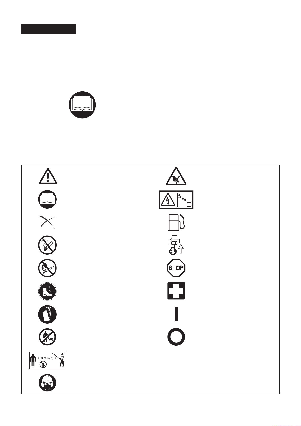
Please note the following symbols when reading this instruction manual
WARNING/DANGER Beware of pinching
Table of Contents Page
SYMBOLS ........................................................................................2
SAFETY INSTRUCTIONS ................................................................3
TECHNICAL DATA ...........................................................................7
DESIGNATION OF PARTS ..............................................................8
CONNECTING THE TRIMMER UNIT TO THE POLE ......................9
FUEL/REFUELLING ....................................................................... 10
PRECAUTIONS BEFORE STARTING THE ENGINE ....................12
OPERATING THE POLE HEDGE TRIMMER ................................15
MAINTENANCE .............................................................................16
STORAGE ......................................................................................21
TROUBLESHOOTING ...................................................................23
Before usage, carefully read and fully
understand the instructions in this manual
PROHIBITION Fuel (Gasoline)
No smoking
No naked ame Emergency stop
Wear protective shoes First aid
Wear protective gloves ON/START
Beware of electrical lines, risk of electrical
shock
Engine manual-start
OFF/STOP
Keep working area clear of persons and
pets
Wear a protective helmet and eye and ear
protection
2
Page 3
SAFETY INSTRUCTIONS
General Instructions
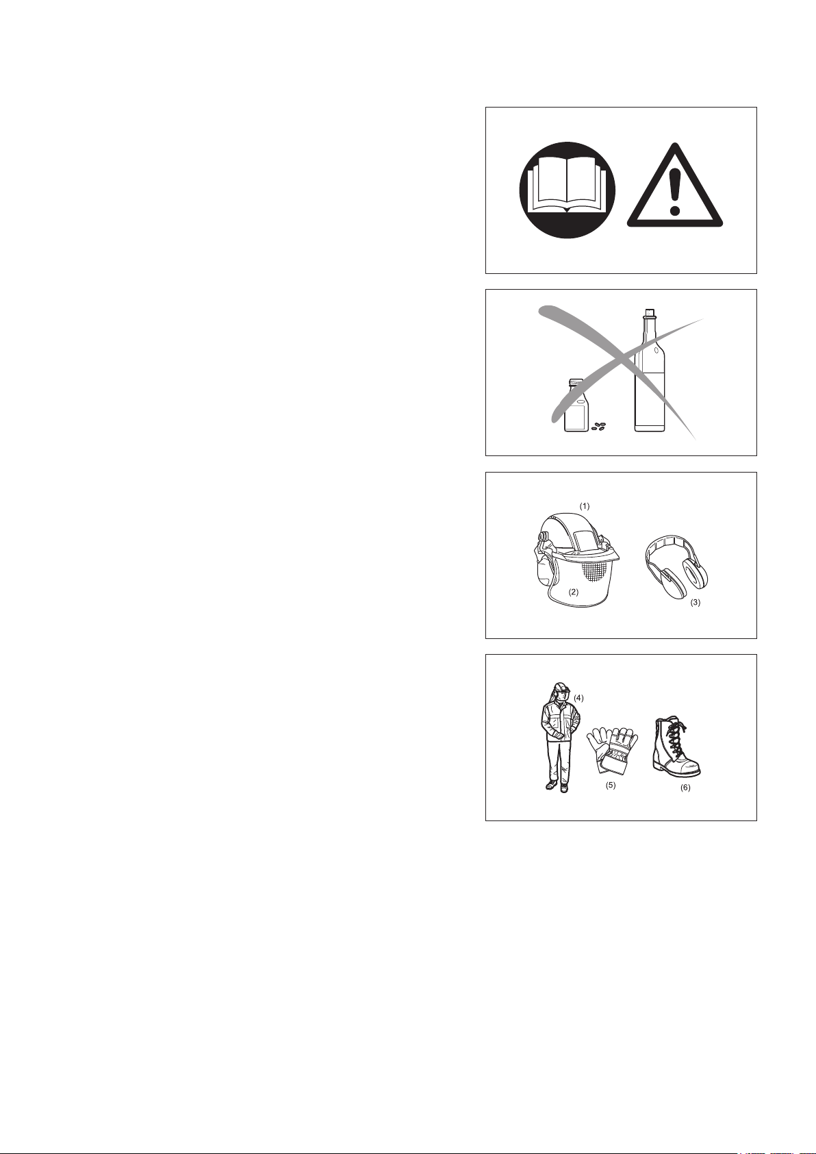
Before usage, carefully read this manual and thoroughly familiarize yourself with how to correctly handle the pole hedge trimmer. THIS EQUIPMENT CAN CAUSE
SERIOUS INJURY IF USED IMPROPERLY!
Always provide detailed instructions on how to correctly use the pole hedge trimmer when lending the equipment to another person. Make sure that the
instruction manual is handed over together with the pole hedge trimmer.
First-time users should ask their dealer for basic instructions on the correct handling of the pole hedge trimmer.
Store this manual in a location where it is easily accessible for quick reference. Do not allow persons under the age of 18 to operate the pole hedge trimmer. Individuals over 16 years old, however, may use the pole hedge trimmer for
training purposes if under the constant supervision of an adult familiar with the
operation of the pole hedge trimmer.
Always use the pole hedge trimmer with the utmost care and attention. Serious injury may result if the pole hedge trimmer is used in the following circumstances. Do not use the pole hedge trimmer:
When feeling tired or ill.•
After consuming alcohol and/or medication.•
At night or in poor lighting conditions.•
During pregnancy.•
Intended use
This pole hedge trimmer has been designed for the sole purpose of trimming hedges and bushes with a maximum branch diameter of 7 mm. Do not use the
trimmer for any other purposes.
Personal protective equipment
Clothes worn should be functional and tight-tting without restricting movement. Do not wear clothing or jewelry that could get entangled in underbrush or in the
machine.
For adequate protection against injuries to head, eyes, feet, hands, as well as hearing impairment, the following protective equipment and clothing must be
used when working with the pole hedge trimmer.
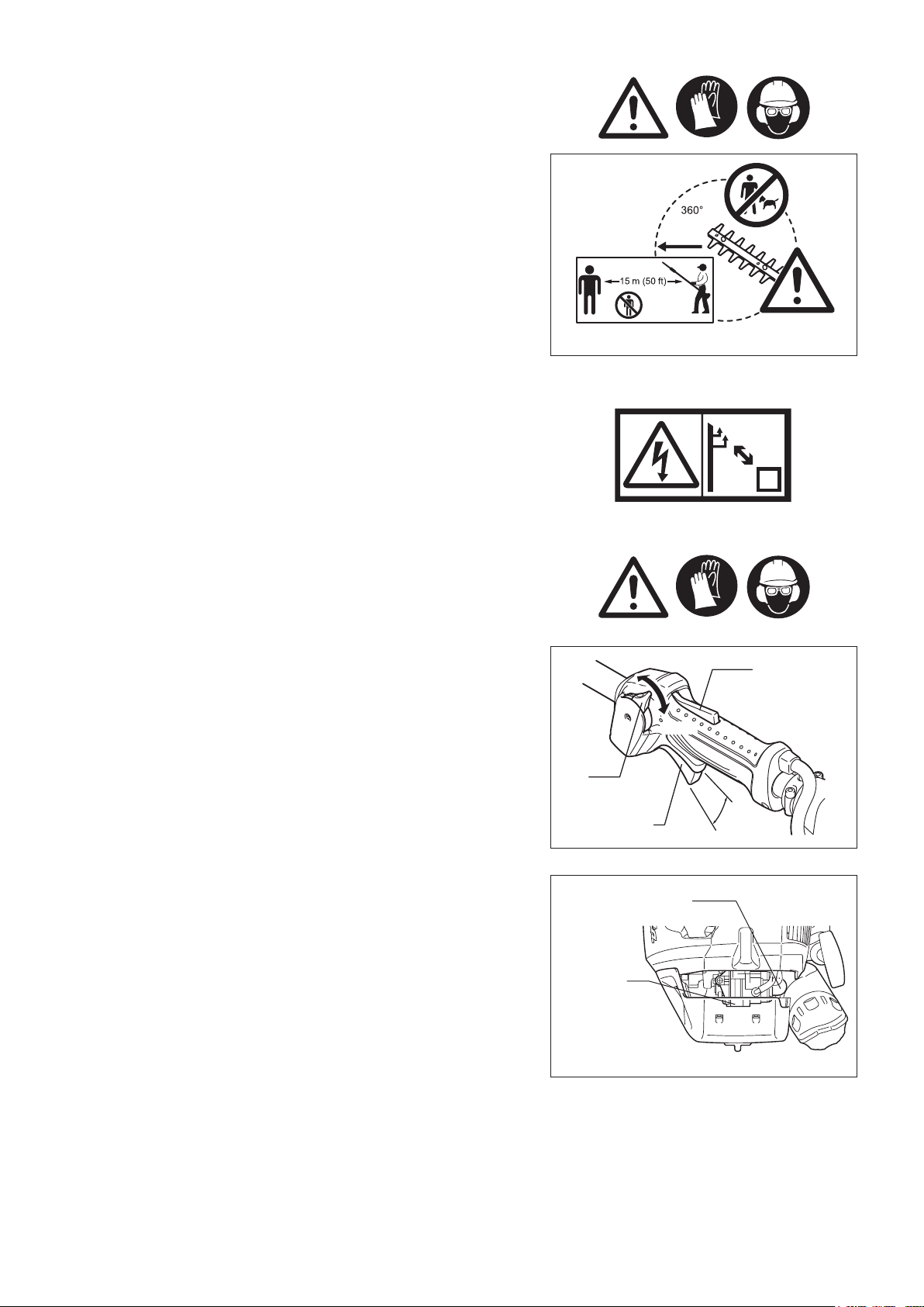
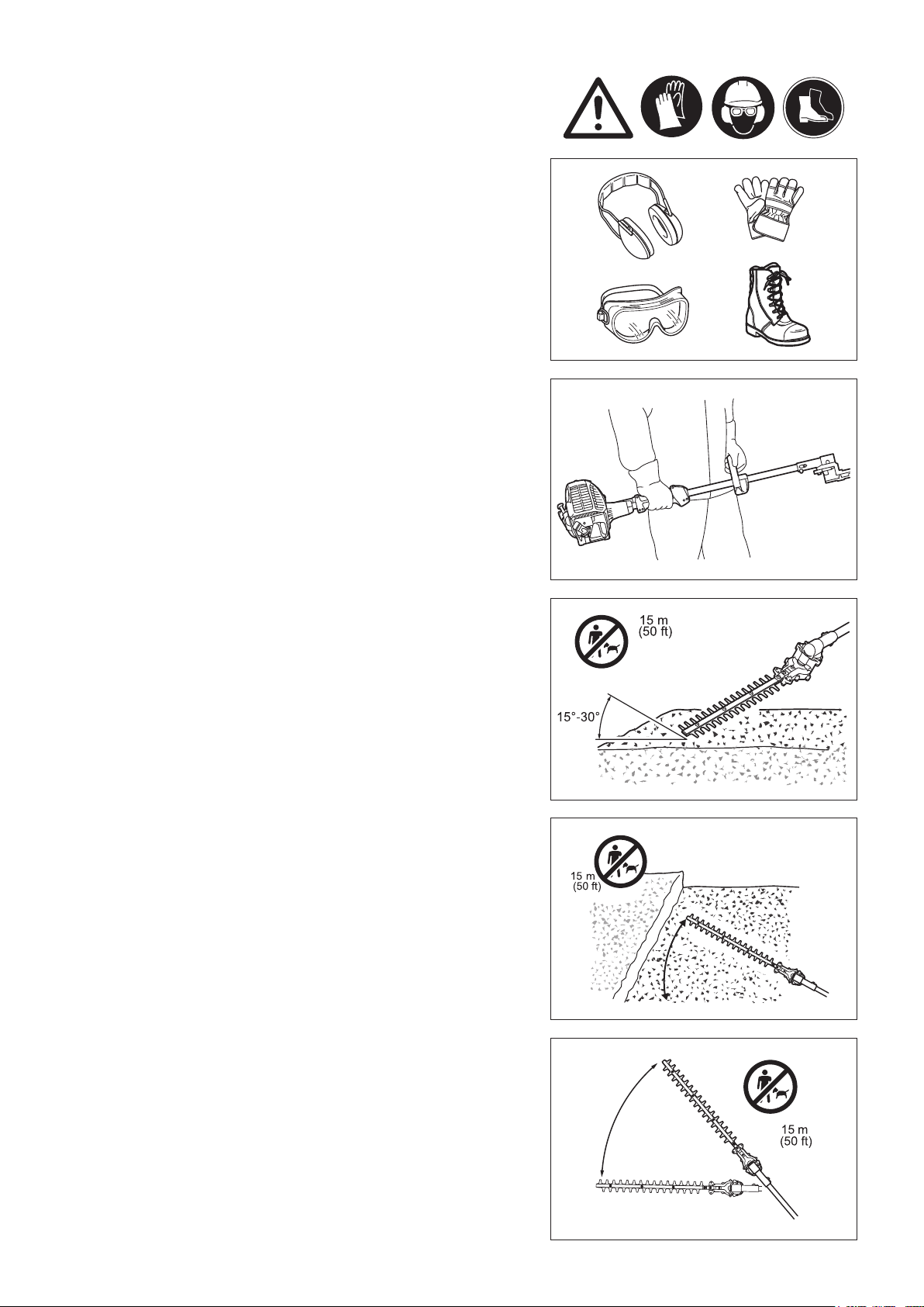
To prevent injury to the head or the eyes, always wear a protective helmet (1) with goggles or a visor (2).
To avoid hearing impairment, wear adequate ear defenders (3) at all times. Use of a well-tting work overalls (4) is strongly recommended. Always wear rugged, leather working gloves (5) when operating the pole hedge trimmer.
When using the pole hedge trimmer, always wear sturdy shoes (6) with a non-slip sole. Special work shoes ensure good footing and protect against injury.
3
Page 4
Starting the pole hedge trimmer
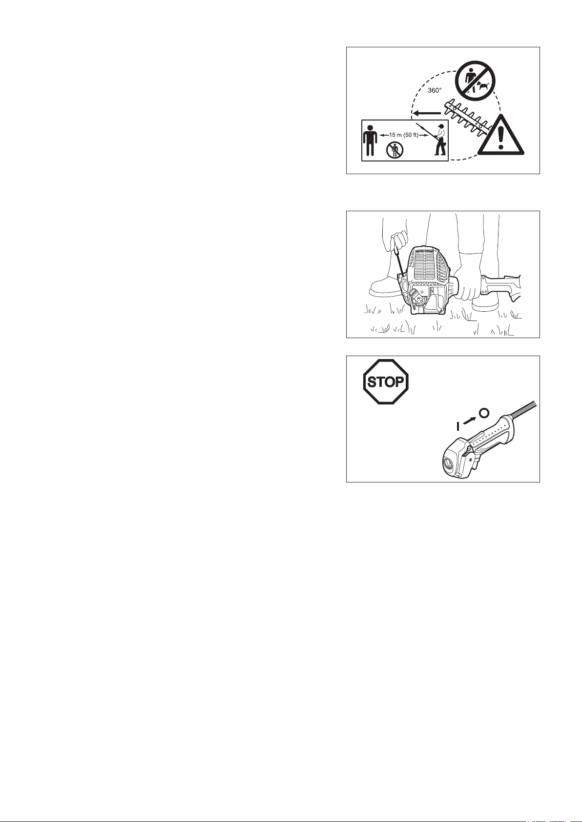
At all times allow a 15-meter diameter safety zone around the working area. Make sure that all persons (in particular, children) and/or animals remain outside
this zone. In general, avoid using the hedge trimmer whenever people (in
particular children) are nearby.
Before starting the pole hedge trimmer, always make sure that the machine is in safe operational condition.
Check the operation of the throttle lever safety mechanism. The lock-off lever should have the smooth and easy actions. Make sure that the lock-off lever
functions properly. Check the handles are clean and dry and test the STOP
switch to ensure that it is functioning properly.
Always start the pole hedge trimmer in accordance with the directions provided in
this instruction manual.
Follow the instructions below to start the pole hedge trimmer
Start the pole hedge trimmer only after the machine has been completely assembled and all accessory parts have been attached.
Before starting the engine, make sure that cutting blades are not obstructed by any foreign objects such as stones, branches, etc.
Stop the engine immediately if engine problems occur. -
During operation, hold both the front and rear handle rmly by wrapping your ngers around the handles. Keep handles clean and free of moisture, resin, oil or
grease.
Always ensure secure and well-balanced footing
Only use the pole hedge trimmer outdoors. Always stop the engine immediately and discontinue operation if engine trouble occurs or if the machine starts making unusual noise.
Exhaust fumes are poisonous. Never operate the machine in an enclosed room or tunnel without ventilation (risk of suffocation and gas poisoning). Note that
carbon monoxide is an odorless gas. Always make sure that areas where the
engine is operated are adequately ventilated.
Stop the engine when resting, or when the pole hedge trimmer is left unattended. Put the machine in a safe location and make sure that no combustible material is
nearby.
Never place a hot hedge trimmer onto dry grass or combustible material. To reduce the risk of re, keep the engine and mufer free of debris, leaves or excessive lubricant.
Never operate the engine if the mufer is malfunctioning. Turn off the engine before transportation. Always stop the engine in the following circumstances. When: -
Resting•
Transporting the machine•
Cleaning the machine•
Refuelling the machine•
Performing maintenance on the machine•
Fixing a problem with the machine•
When transporting the machine in a vehicle, always securely attach the pole hedge trimmer to avoid leakage of residual fuel.
Always empty the fuel tank before transporting the pole hedge trimmer in a vehicle.
When unloading the machine from a vehicle, take extra care not to drop the pole hedge trimmer to the ground, as this may seriously damage the fuel tank.
Except in an emergency, never drop the pole hedge trimmer as this may seriously damage the machine.
Resting Transporting the machine Cleaning the machine Refueling the machine Performing maintenance on -
the machine
Fixing a problem with the -
machine
4
Page 5
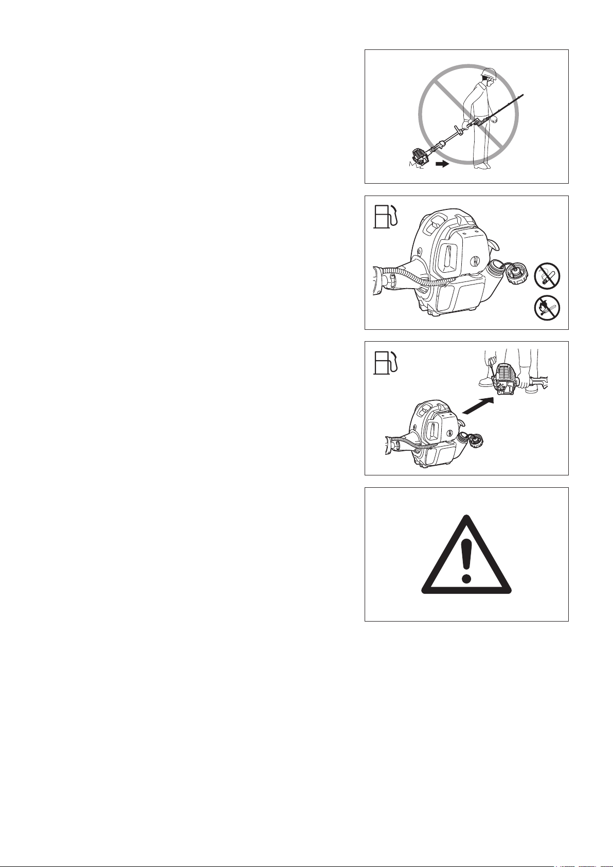
When transporting the pole hedge trimmer, always lift the machine completely off of the ground. Never drag the engine across the ground as this may damage the
fuel tank and possibly cause a re.
Always use the cutter cover provided to protect and secure the cutting section of the pole hedge trimmer during transportation and storage.
Refuelling
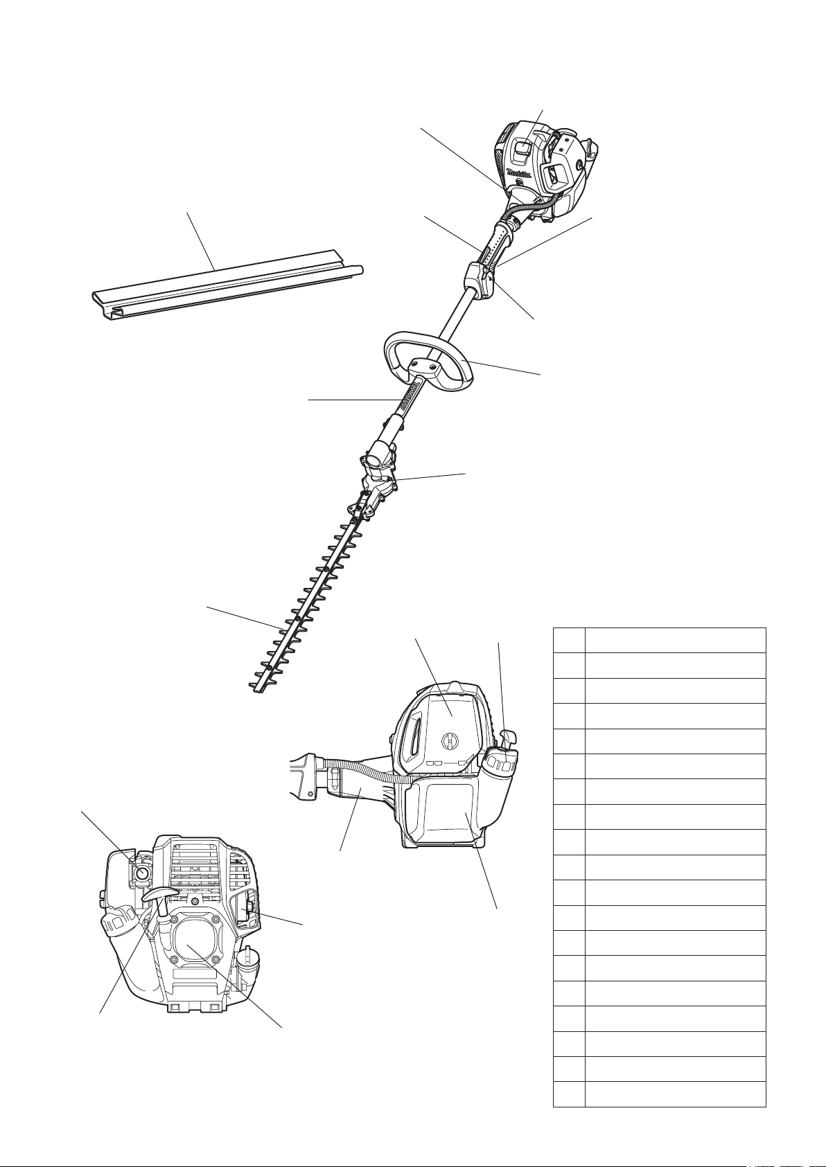
Before refuelling, stop the engine. Never refuel near naked ames. Do not smoke when refuelling. Always allow sufcient time for the engine to cool down before refuelling. Take care not to let your skin come into contact with petroleum products. Do not inhale gasoline fumes and always wear protective gloves when refuelling.
Change and clean protective wear at regular intervals.
Take extra care to avoid spilling gasoline and oil in order to avoid contamination of the ground. If gasoline or oil has been spilled onto the hedge trimmer,
immediately wipe the surface of the hedge trimmer with a rag.
Dry the cloths used for wiping the fuel at a well ventilated area before disposing
them. Failure to do so may cause spontaneous combustion.
Make sure that no fuel comes in contact with your clothes. Change fuel -
contaminated clothes immediately (re hazard).
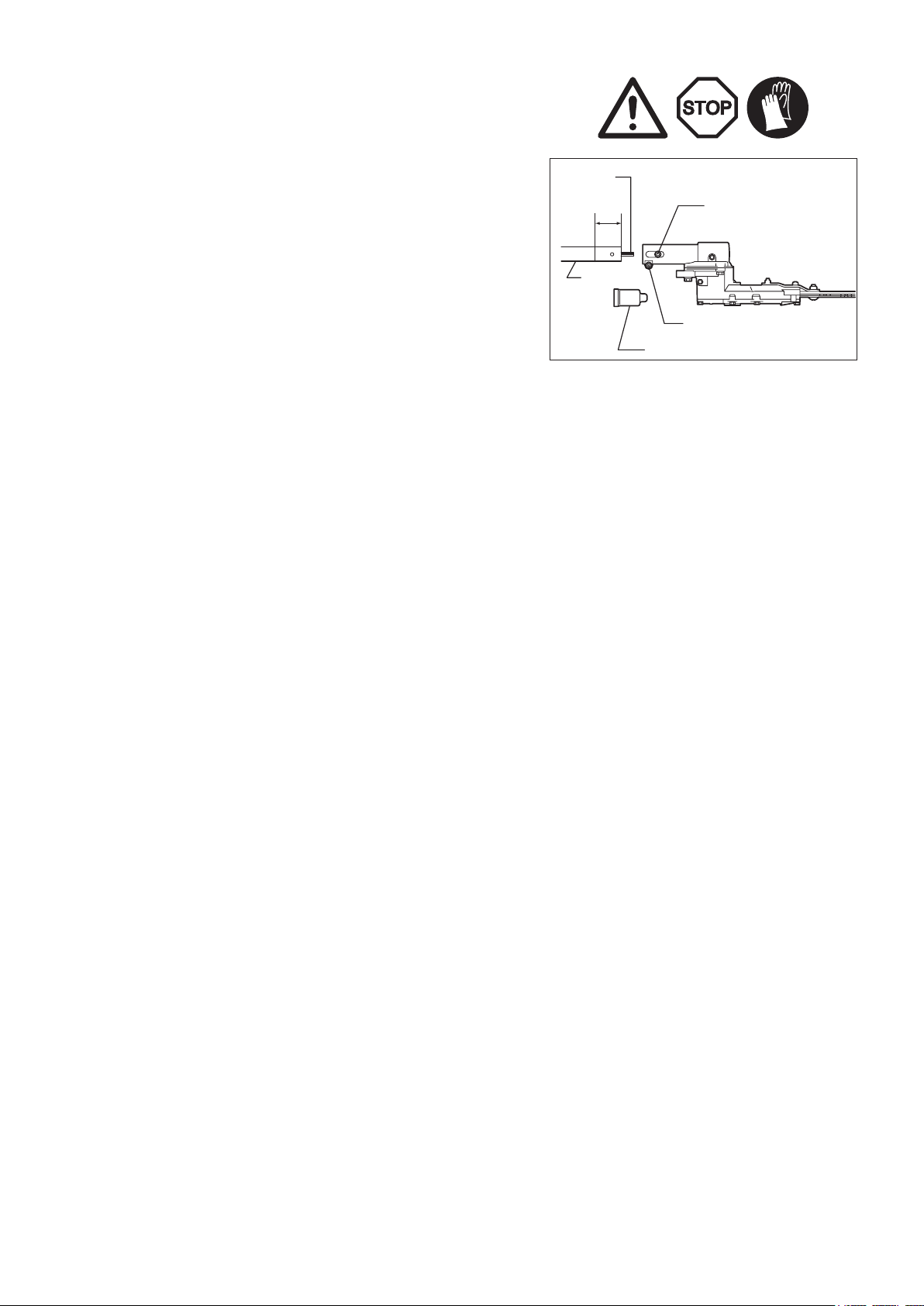
Close the fuel tank and tighten the fuel tank cap securely. To restart the engine, transfer the pole hedge trimmer to a location at least 3 meters away from the
place of refuelling.
Check the fuel tank cap at regular intervals to make sure that the cap is securely fastened.
Never refuel the machine in an enclosed room. Fuel vapors accumulate at ground level (risk of explosion).
Store fuel in appropriate containers only, and make sure that stored fuel is out of the reach of children.
3 m
Operation
During operation, hold the pole hedge trimmer with both hands at all times. Only use the pole hedge trimmer in a good light and visibility conditions. Beware of slippery and wet areas (ice and snow) during the cold season (danger of
slipping), and always ensure secure footing.
Never use the pole hedge trimmer while standing on an unstable surface or a steep slope.
Never use the pole hedge trimmer while standing on a ladder. Never climb a tree to use the pole hedge trimmer from the tree. To avoid stumbling or falling over objects, never walk backwards when working with the pole hedge trimmer.
Always stop the engine before cleaning or servicing the machine. Also, refrain from replacing parts before the engine has been stopped.
Do not operate the pole hedge trimmer if the cutting unit is damaged or worn. -
5
Page 6

Maintenance instructions
Always do your utmost to keep pollution and noise emissions as low as possible when operating the pole hedge trimmer. Pay special attention to correct
adjustment of the carburetor.
Clean the hedge trimmer at regular intervals and periodically check whether all nuts and bolts are securely tightened.
Never service or store the pole hedge trimmer in the vicinity of naked ames, sparks, etc.
Empty the fuel tank before storage, and always store the pole hedge trimmer in a well-ventilated locked room. Make sure the pole hedge trimmer is out of children’s
reach at all times.
To prevent further damage and/or personal injury, refrain from repairing a -
malfunctioning pole hedge trimmer if not qualied to do so. For repairs always
contact your dealer or an authorized service agent.
Do not attempt to modify or remodel the pole hedge trimmer as this may affect
operation safety.
Maintenance work that can be performed by the user is limited to the activities
described in this instruction manual. Any other procedures are to be executed by an
authorized service agent.
Use only genuine spare parts and accessories supplied by MAKITA via authorized
service centers.
Use of unauthorized accessories and tools may increase the risk of accident and
injury. MAKITA accepts no liability whatsoever for accidents or damage resulting
from the use of unauthorized accessories and parts.
First aid
As a precaution for the occurrence of an accident, make sure that a fully stocked
rst aid kit is ready at hand.
Replace any items taken from the rst aid kit as soon as possible.
When asking for help in the case of an emergency, give the
following information:
Place of accident•
What happened•
Number of injured people•
Extent of injuries•
Your name•
6
Page 7

TECHNICAL DATA: EN5550SH
Model
EN5550SH
Loop handle
Dimensions (L x W x H) in (mm) 69-1/4” x 9-1/2” x 9-1/2” (1,760 mm x 243 mm x 241 mm)
Mass lbs (kg) 14.1 (6.4)
Volume (fuel tank) .oz (l) 20.3 (0.6)
Cutting length in (mm) 20-1/2” (520)
3
Engine displacement cu.in (cm
Maximum engine performance hp (kW) 1.1 at 7,000/min (0.77 at 7,000 min
) 1.5 (25.4)
-1
)
Stroke per minute 4,600
Fuel consumption kg/h 0.33
Specic fuel consumption g/kWh 408
Idling speed RPM 3,000
Clutch engagement speed RPM 4,400
Carburetor
(Diaphragm carburetor)
type WALBRO WYL
Ignition system type Solid state ignition
Spark plug type NGK CMR4A
Electrode gap in (mm) 1/32” (0.7-0.8)
Fuel Automobile gasoline
Engine oil
SAE 10W-30 oil of API Classication
Class SF or higher (4-stroke engine for automobile)
Gear ratio 1/4.25
7
Page 8
DESIGNATION OF PARTS
1
2
3
4
5
6
7
8
9
10
11
12
13
14
15
16
17
18
Designation of parts
1 Throttle cable
2 Lock-off lever
3 Throttle lever
4 Stop switch
5 Handle
6 Shaft
7 Gear box
8 Cutter blade
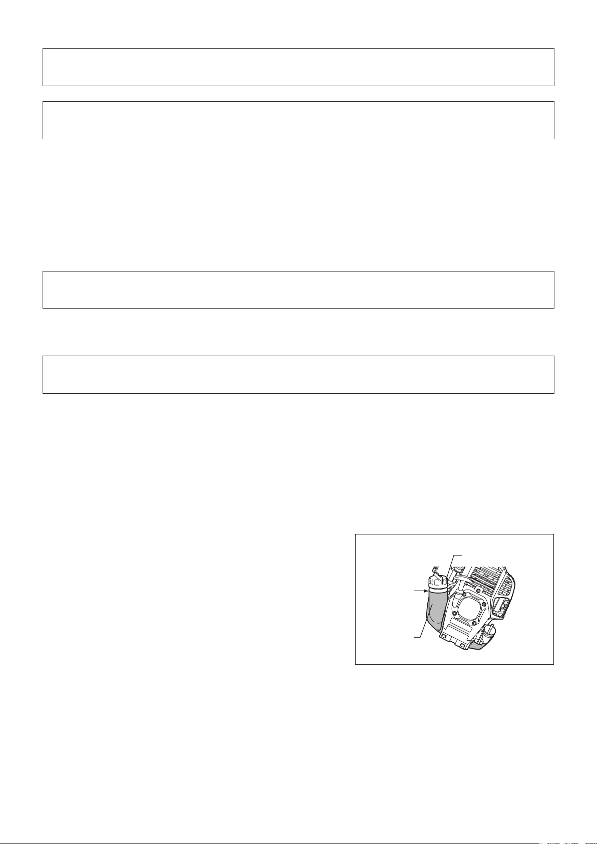
9 Air cleaner
10 Fuel tank cap
11 Fuel tank
12 Clutch case
13 Spark plug
14 Primer pump
15 Mufer
8
16 Recoil starter
17 Starter knob
18 Blade cover
Page 9
CONNECTING THE TRIMMER UNIT TO THE
40 mm
POLE
Important:
Make sure that the engine is turned off, and remove the spark plug cap before
assembling the pole hedge trimmer.
Wear protective gloves!
Secure cutting blades with the blade cover provided when connecting the trimmer
unit to the pole.
Remove the cap from the shaft. Loosen the M5 x 12 screw and M5 x 25 bolt. Insert shaft into gear case -
Drive axle
M5 x 10 screw
Shaft
NOTE: Make sure that the shaft is completely inserted into the gear case
(approx. 40 mm/1.57”).
If you are having trouble inserting the shaft, manually rotate the drive axle a
little and try again.
Make sure that the shaft is properly inserted and then tighten the M5 x 12 screw and the M5 x 25 bolt.
M5 x 25 bolt
Cap
9
Page 10
FUEL/REFUELLING
BEFORE START OF OPERATION
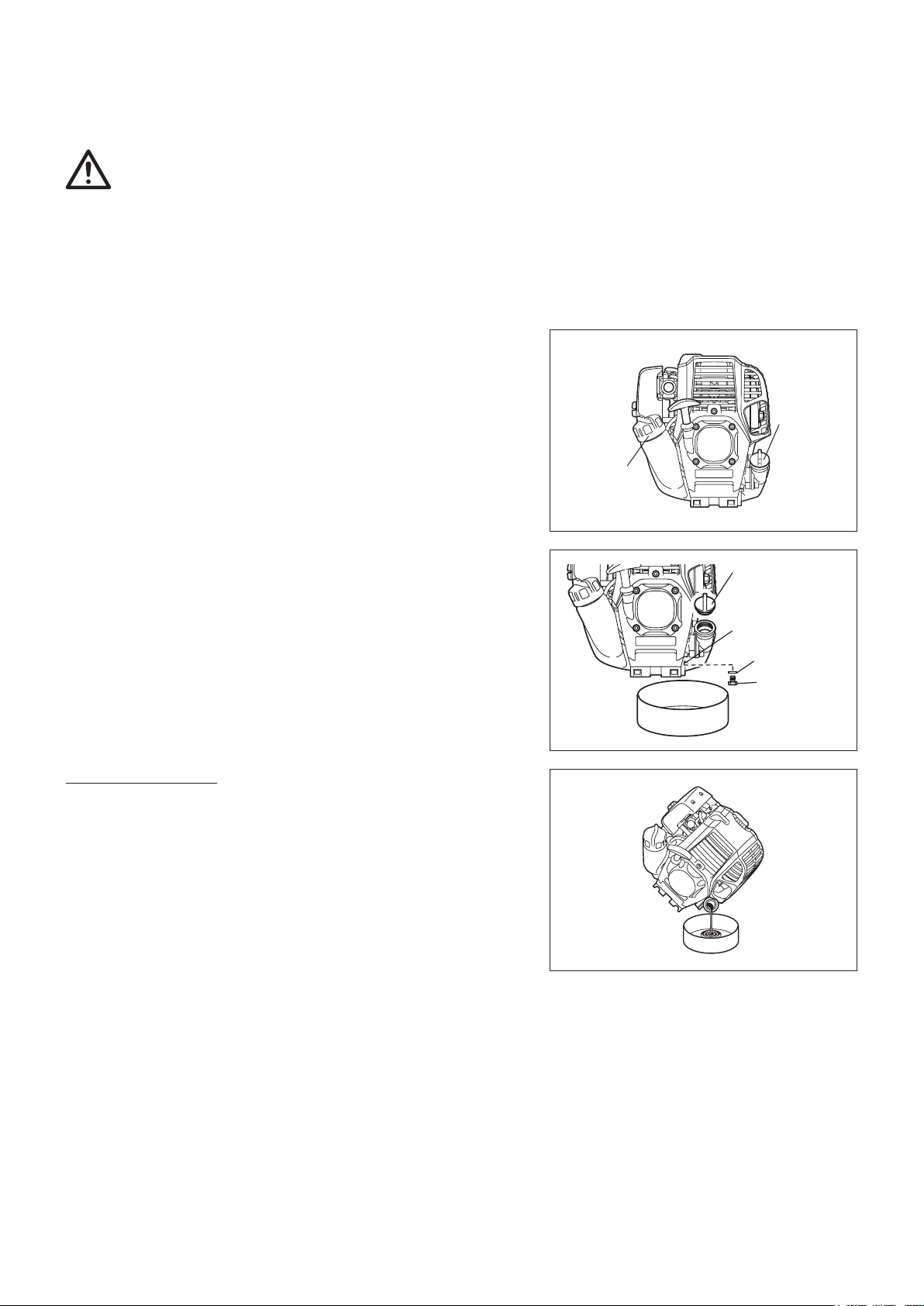
Inspection and rell of engine oil
Perform the following procedure, with the engine cooled down. Set the engine level, remove oil cap (Fig. 1), and check to see whether or not there is oil in the range between the upper limit and lower limit marks of the oil pipe (Fig. 2).
Top up with oil to upper limit mark if oil is insufcient (oil level is close to lower limit mark) (Fig. 3). The area surrounding the external marks is transparent, so the amount of oil inside can be checked without having to remove the oil cap. However, if oil pipe becomes extremely dirty, visibility may be lost, and oil level will have to be checked against stepped section on inside of
oil pipe.
For reference, the oil rell time is about 10 h (10 times or 10 tanks of oil rell). If the oil changes in color or mixes with dirt, replace it with new one. (For the interval and method of replacement, refer to P18)
Recommended oil: SAE 10W-30 oil of API Classication, Class SF or higher (4-stroke engine for automobile)
Oil volume: Approx. 0.08 L
NOTE: If the engine is not kept upright, oil may go into around the engine, and may be relled excessively.
If the oil is lled above the limit, the oil may be contaminated or may catch re with white smoke.
Point 1 in Replacement of oil: “Oil cap”
Remove dust or dirt near the oil rell port, and detach the oil cap. Keep the detached oil cap free of sand or dust. Otherwise, any sand or dust adhering to the oil cap may cause irregular oil circulation or wear on the engine parts, which will result in troubles.
Oil cap
Internal stepped
section (upper limit)
Internal stepped
section (lower limit)
Oil pipe
Fig. 1 Fig. 2 Oil pipe Fig. 3
(1) Keep the engine level, and detach the oil cap.
External mark
(upper limit)
External mark
(lower limit)
Top up with oil
until oil level
reaches internal
stepped section
(upper limit).
The area between the
external upper and lower
limits is transparent, so
oil level can be checked
extternally against these
marks.
(2) Fill with oil to upper limit mark. (see Fig. 3)
Use oil bottle when lling.
(3) Securely tighten the oil cap. Insufcient tightening may cause oil leakage.
10
Page 11
Do not replace oil with the engine in a tilted position.•
Filling with oil while engine is tilted leads to overlling which causes oil contamination and/or white smoke.•
Point 2 in Replacement of oil: “If oil spills out”
If oil spills out between the fuel tank and engine main unit, the oil is sucked into through the cooling air intake port, which will contaminate the engine. Be sure to wipe out spilled oil before start of operation.
Note
REFUELLING
Handling of fuel
It is necessary to handle fuel with utmost care. Fuel may contain substances similar to solvents. Refuelling must be performed in a sufciently
ventilated room or in the open air. Never inhale fuel vapors, and keep fuel away from you. If you touch fuel repeatedly or for a long time, the
skin becomes dry, which may cause skin disease or allergy. If fuel comes into the eye, clean the eye with fresh water. If your eye remains still
irritated, consult your doctor.
Storage period of fuel
Fuel should be used within a period of 4 weeks, even if it is kept in a special container in a well-ventilated and shaded area.
Otherwise, fuel may deteriorate in one day.
STORAGE OF MACHINE AND REFILL TANK
Keep the machine and tank at a cool place free from direct sunshine. Never keep the fuel in a car. -
Fuel
The engine is a four-stroke engine. Be sure to use an automobile gasoline (regular gasoline or premium gasoline).
Points for fuel
Never use a gasoline mixture which contains engine oil. Otherwise, it will cause excessive carbon accumulation or mechanical troubles. Use of deteriorated oil will cause irregular start-up. -
Refuelling
WARNING: INFLAMMABLES STRICTLY PROHIBITED
Gasoline used: Automobile gasoline (unleaded gasoline)
Loosen the tank cap a little to release the tank pressure. Detach the tank cap, and refuel, discharging air by tilting the fuel tank so that the refuel port will be oriented upward. (DO NOT ll fuel up to the top of the tank.)
Wipe well the periphery of the tank cap to prevent foreign matter from entering the fuel tank. After refuelling, securely tighten the tank cap. -
If there is any aw or damage on the tank cap, replace it.•
The tank cap wears out in course of time. Replace it every two to three years.•
Fuel tank cap
Fuel upper
limit
Fuel tank
11
Page 12
PRECAUTIONS BEFORE STARTING THE
ENGINE
At all times allow a 15-meter diameter safety zone around the working area. Make sure that all persons (in particular children) and/or animals remain outside
this zone.
Before using the pole hedge trimmer, make sure that the machine is in safe operational condition. Make sure that the cutting blades are not damaged, and
check the throttle lever for easy action. Make sure that the cutting blades are
not in motion when the engine is idling. If the machine is not operating normally,
contact your dealer to have the machine adjusted. Make sure that the handles
are clean and dry, and test whether the I-O switch is functioning properly. Start
the engine only in accordance with the instructions given in this manual. Do
not use any other methods to start the pole hedge trimmer (see, “Starting the
Engine”).
Start the engine of the pole hedge trimmer only after having read and fully understood the instructions. Never attempt to start a pole hedge trimmer that has
not been fully assembled. Serious injury may result otherwise.
Before starting the engine, always make sure that the cutting blades are not obstructed by stones, branches or any other solid objects.
Check the working area for wires, cord, glass or other foreign objects that could get caught in the cutting blades.
Electrical shock: Be aware of all electrical lines in the vicinity. Check the entire work area for the presence of power lines and electrical fences before starting to
work.
POINTS IN OPERATION AND HOW TO STOP
Observe the applicable accident prevention regulations!
STARTING
Move at least 3 m away from the place of refuelling. Put the pole hedge trimmer on
a clean piece of ground taking care that the cutting blades do not come into contact
with the ground or any other objects.
A: Cold start
1) Set this machine on a at space.
2) Set the I-O switch (1) to OPERATION.
3) Primer pump
Continue to push the primer pump until the fuel comes into the primer pump. (In
general, fuel comes into the primer pump by 7 to 10 pushes.) If the primer pump
is pushed excessively, an excess of gasoline returns to the fuel tank.
(1)
Throttle lever
Carburetor
OPERATION
STOP
Low speed
Primer pump
Lock-off lever
High
speed
12
Page 13
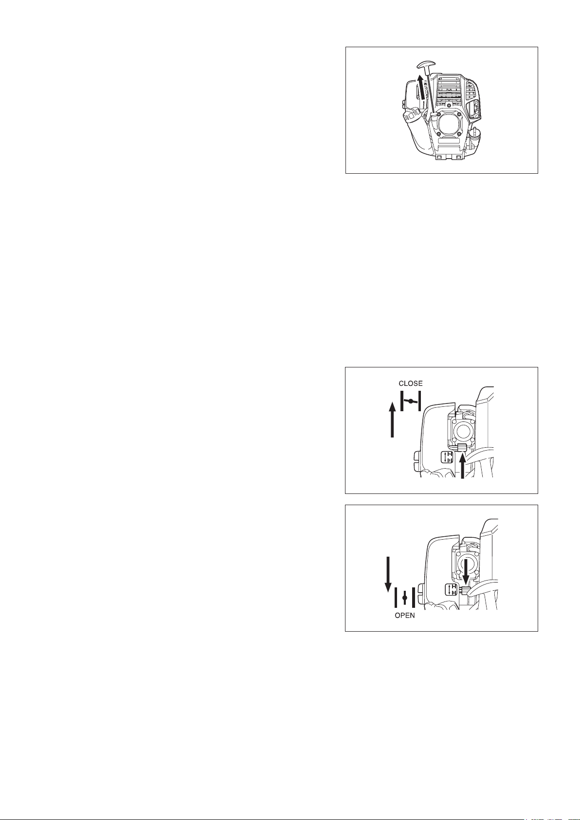
4) Recoil starter
Pull the start knob gently until it is hard to pull (compression point). Then, return
the start knob, and pull it strongly. Never pull the rope to the full extension. Once
the start knob is pulled, never release your hand immediately. Hold the start
knob until it returns to its original point.
5) Warm-up operation
Continue warm-up operation for 2 to 3 minutes.
NOTE: In case of excessive fuel intake, remove the spark plug and pull the starter
handle slowly to remove excess fuel. Also, dry the electrode section of the
spark plug.
Caution during operation:
If the throttle lever is opened fully in a no-load operation, the engine speed is
increased to 10,000 min
speed than required and at an approximate speed of 6,000 - 9,000 min
B: Startup after warm-up operation
1) Repeat pushing the primer pump gently.
2) Keep the throttle lever at the idling position.
3) Pull the recoil starter strongly.
4) If it is difcult to start the engine, open the throttle by about 1/3.
Pay attention to the cutting blades which may move.
-1
(rpm) or more. Never operate the engine at a higher
-1
(rpm).
At times, such as winter, when starting the engine is difcult Operate choke
lever with the following procedure when starting engine.
After implementing startup steps 1) to 3), set choke lever to the CLOSE position.•
Implement startup step 4) and start engine.•
Once engine starts, set choke lever to the OPEN position.•
Implement startup step 5) and complete warm up.•
CAUTION: If a bang (explosive sound) is heard and the engine stops, or the
just-started engine stalls before the choke lever is operated, return the
choke lever to the OPEN position, and pull the starter knob a few times
again to start the engine.
CAUTION: If the choke lever is left in the CLOSE position, and the starter knob
merely pulled repeatedly, to much fuel will be sucked in, and the engine
will become difcult to start.
13
Page 14
STOPPING
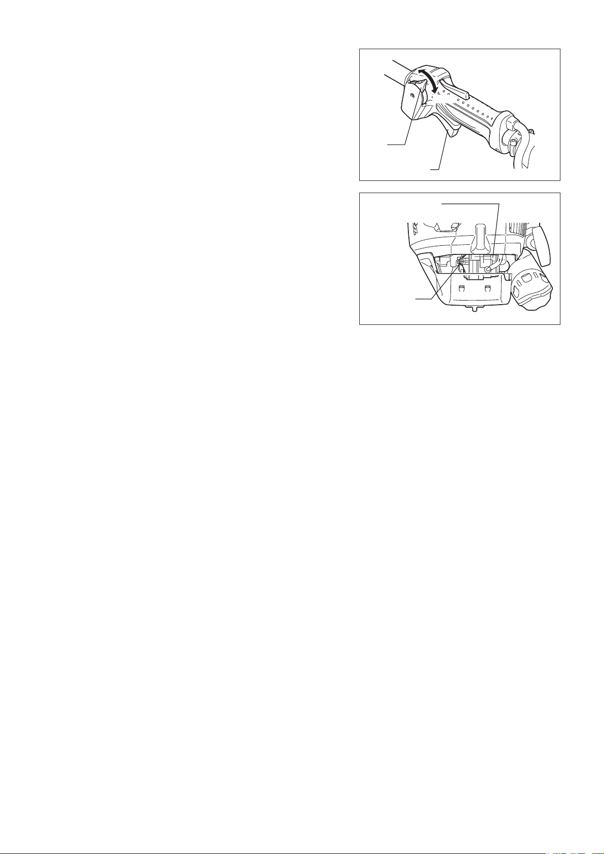
1) Release the throttle lever (2) fully, and when the engine speed has lowered, set
the I-O switch to STOP the engine will now stop.
2) Be aware that the cutting head may not stop immediately and allow it to slow
down fully.
ADJUSTMENT OF LOW-SPEED ROTATION (IDLING)
When it is necessary to adjust the low-speed rotation (idling), perform it by the
carburetor adjusting screw.
CHECKUP OF LOW-SPEED ROTATION
Set the low-speed rotation to 3,000 rpm (/min). If it is necessary to change the rotation speed, regulate the adjusting screw
(illustrated on the right), with Phillips screwdriver.
Turn the adjusting screw to the right, and the engine speed will increase. Turn the adjusting screw to the left, and the engine speed will drop.
The carburetor is generally adjusted before shipment. If it is necessary to readjust it, please contact Authorized Service Agent.
STOP
(1)
(2)
Carburetor
Adjusting
screw
14
Page 15
OPERATING THE POLE HEDGE TRIMMER
When working with the pole hedge trimmer, rmly grasp the handles with both hands.
Do not touch the cutting blade portion of the pole hedge trimmer during operation, or when the engine is running.
Take extra care not to inhale exhaust gases when working with the pole hedge trimmer. Never operate the pole hedge trimmer in an enclosed room or an area
with insufcient ventilation (risk of suffocation and gas poisoning). Note that
carbon monoxide is an odorless gas that is, it cannot be detected by the sense of
smell.
Always wear adequate protective wear before starting to work with the pole hedge trimmer.
Stop the engine immediately if the mufer is not functioning properly. Only use the pole hedge trimmer in good light and visibility conditions. Do not operate the pole hedge trimmer in darkness or fog. Beware of slippery and wet areas (ice and snow) during the cold season (danger of slipping), and always
ensure secure footing.
Never use the pole hedge trimmer while standing on an unstable surface or a steep slope.
Never use the pole hedge trimmer while standing on a ladder. Never climb a tree to use the pole hedge trimmer from the tree. Continuously check the working area for wires, cord, glass or other foreign objects that could get caught in the cutting blades.
Make sure that the cutting blades are in rapid motion before starting to cut. Always grip the pole hedge trimmer with both hands and maintain a rm grip when working with the machine.
To assure optimal control over the pole hedge trimmer, always completely wrap your hands around the handles (use your thumb for counter pressure) and apply
a rm grip on the handles.
Note that the cutting blades will remain in motion for up to two seconds after the throttle lever has been released.
Do not cut with the pole hedge trimmer at low engine speed. The speed of the cutting blades cannot be adjusted properly with the throttle lever when the engine is running at low speed.
To trim the top surface of a hedge, rst align the cutting blades at an angle of 15° - 30° in the cutting direction and keep the pole hedge trimmer in a horizontal
position. Then start trimming the hedge using a swinging movement, much like
drawing circle segments with the hedge trimmer shaft.
To trim the sides of a hedge, align the blades parallel to the surface to be cut and start trimming with semi-circular upward (down-up) movements.
Pay attention when trimming a hedge close to or against wire fences. Do not touch hard objects such as wire fence, stone or ground with the cutting blades. It may cause blades to crack, chip or break.
Do not use the pole hedge trimmer over an extended period of time. As a general rule, for every 50 minutes of operation take a 10-20 minutes rest.
If the cutting blades come into contact with stones or other solid objects, stop the engine immediately and check the blades for damage. Replace the blades if
damaged.
If the pole hedge cutter develops a problem during operation (strange noises, vibration, etc.), immediately stop the engine. Do not use the machine again until
the problem has been recognized and solved.
Always do your utmost to keep pollution and noise emissions as low as possible when operating the pole hedge trimmer. Pay special attention to correct
carburetor adjustment.
If thick branches get jammed in the cutting blades, immediately stop the engine, lay the equipment on the ground and remove the obstruction. Check the blades
for damage before using the machine again.
15
Page 16
MAINTENANCE
1
2
3
4
5
6
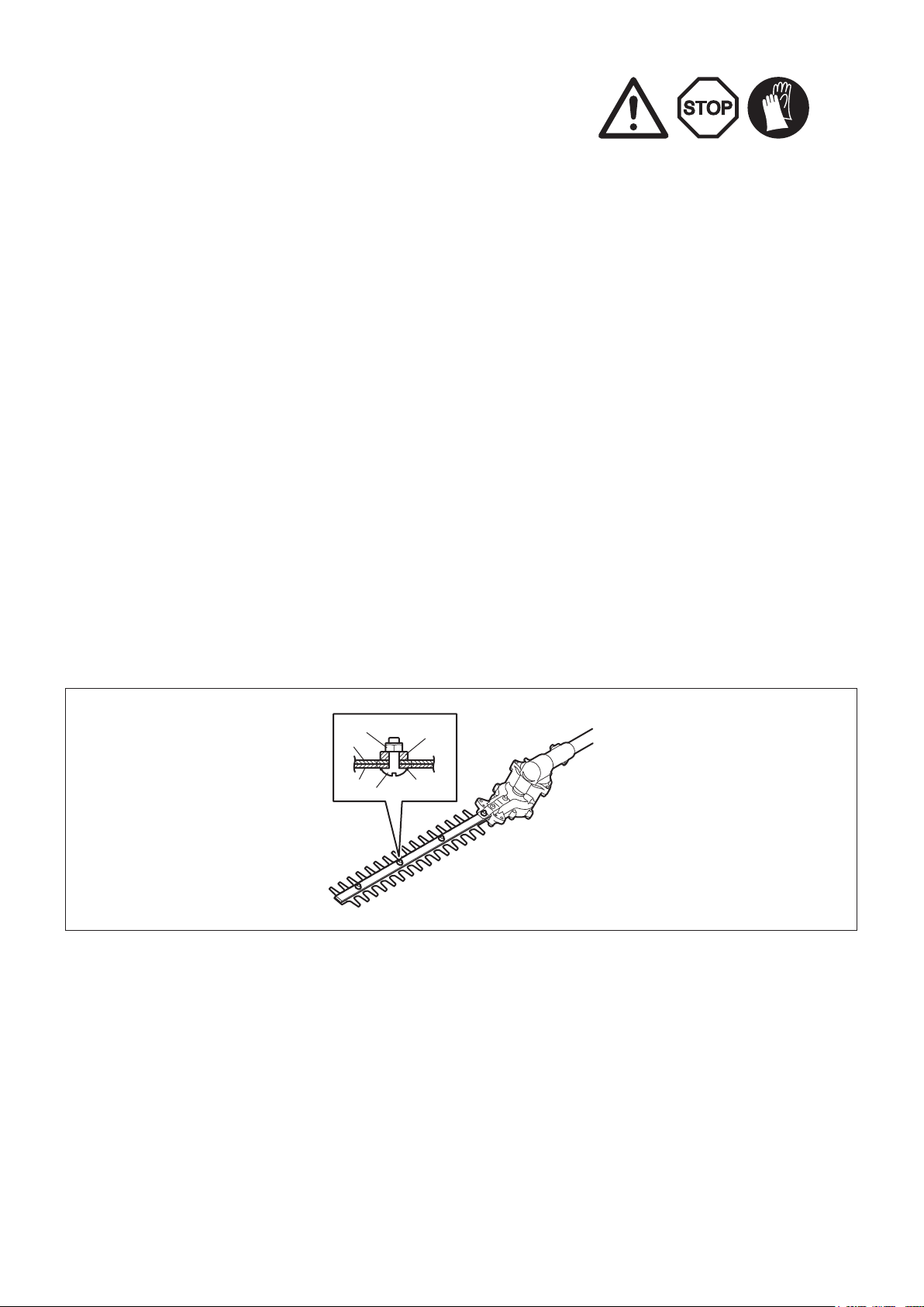
Before performing any maintenance work on the pole hedge cutter (blade cleaning, etc.), always stop the engine and wait until the engine has cooled down.
As an additional safety precaution, also remove the spark plug cap.
Do not try to straighten or weld bent or broken cutting blades. Always replace damaged blades.
Stop the engine at regular intervals to check the cutting blades for possible damage (perform a tapping-resonance test to detect hard-to-see hairline cracks).
Always make sure that the teeth of the blades are sharp.
Clean the pole hedge trimmer regularly. During cleaning also check all screws, nuts and bolts are well tightened.
To reduce the risk of re, never service or store the pole hedge trimmer in the vicinity of open res.
Always wear rugged protective gloves when handling the cutting blades. Contact your dealer for replacement cutting blades. Never use gasoline, benzine, thinner, alcohol or the like. Discoloration, deformation or cracks may result.
Sharpening the blade
If the cutting blades have become blunt and cutting performance is poor, have the
blades sharpened by an authorized service agent.
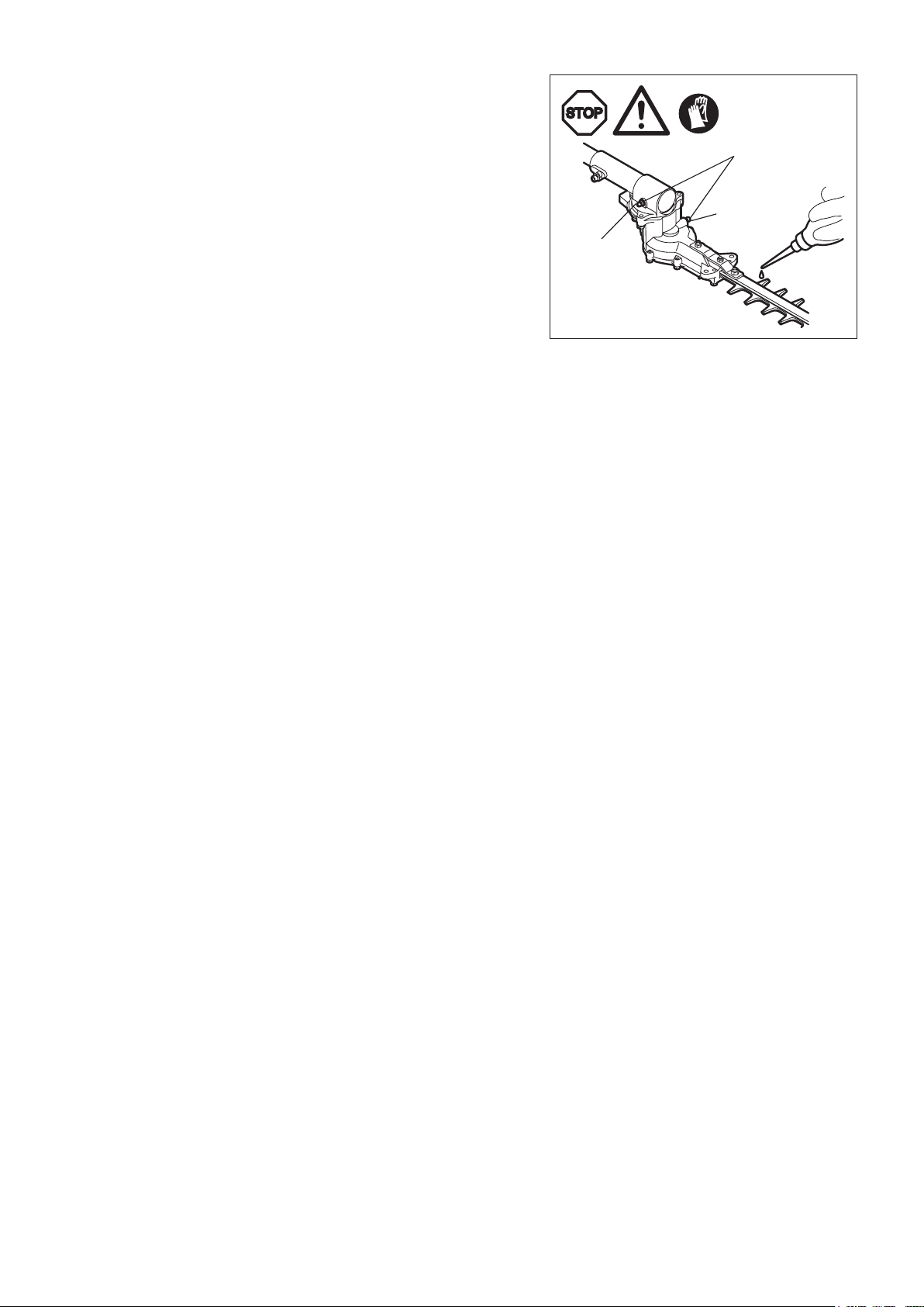
Adjusting blade clearance
The upper/lower blades wear. If you cannot get a clean cut though the blades are sharp enough, adjust the clearance as follows.
1. Loosen the nut (1) with a box or open-ended wrench.
2. Tighten the truss bolt (2) with a hex wrench lightly till it stops and screw it back between a quarter turn and a half turn.
3. Tighten the nut (1), holding the truss bolt (2).
4. Apply light oil on the friction surface of the blades.
5. Start the engine, operate the throttle on and off for a minute.
6. Stop the engine and touch the surface. If they are not too hot to touch, you have made a proper adjustment. If they are too hot to touch, turn
the truss bolt (2) back a little and repeat the step 5 to 6.
NOTE: Before making the adjustment, stop the engine and wait for the blades to stop.
The blades have a slot around the truss bolt (2). In case you nd dust in the end of any of the slots, clean it.
1 Hexagonal U-nut
2 Truss bolt
3 Flat washer
4 Blade guide
5 Upper blade
6 Lower blade
16
Page 17
Adding grease and lubricant
Important: Make sure that the surface of gear box is completely cold before
lubricating.
The gearbox of the pole hedge trimmer should be greased every 15 working hours. Add approx. 5 g of lubricant (Shell Alvania No. 3 or equivalent) to the
point A of the gearbox and 20 g of the lubricant to the point B respectively via the
grease nipples. (Some grease will emerge from the head of the gearbox (located
at the base of the blades) when the pole hedge trimmer is set in motion the rst
time after greasing. Use this as a rough indicator for the amount of grease to be
supplied.)
Grease nipple
Point B
NOTE: Observe greasing intervals and the amount of grease to be supplied.
Mechanical parts of the pole hedge trimmer may be damaged if grease
is not supplied at the prescribed intervals or if an insufcient amount of
grease is added.
Daily inspection and maintenance
To ensure a long service life of your pole hedge trimmer, perform the
followinginspections and maintenance on a daily basis.
Before use; -
Always check for loose or missing parts before starting operation. Pay special •
attention to the cutting unit and make sure that the cutting blade lock screws
are well tightened.
Check for clogging of the cooling air passages and the cooling ns of the •
cylinder before starting operation. Clean if necessary.
After use; -
Clean the hedge trimmer externally and inspect for damage.•
Clean the air lter. Clean the lter several times a day if working in extremely •
dusty conditions.
Check the cutting blades for damage. Make sure that the blades are securely •
mounted.
If the cutting blades still continue to run at idle after the adjustment, consult •
your nearest authorized service agent.
Point A
17
Page 18
REPLACEMENT OF ENGINE OIL
Deteriorated engine oil will shorten the life of the sliding and rotating parts to a great extent. Be sure to check the period and quantity of
replacement.
DANGER: In general, the engine main unit and engine oil still remain hot just after the engine is stopped. In replacement of oil, make
sure that the engine main unit and engine oil are sufciently cooled down. Otherwise, there may remain a risk of scald.
Allow sufcient time after stopping engine for the engine oil to return to the oil tank to ensure accurate reading of the oil
level indicator.
NOTE: If the oil lled above the limit, it may become dirty or may catch re with white smoke.
Interval of replacement: After rst 20 operating hours, followed by every 50 operating hours
Recommended oil: SAE10W-30 oil of API Classication SF Class or higher (4-stroke engine oil for automobile)
In replacement, perform the following procedure.
1) Make sure that the fuel tank cap is tightened securely.
2) Put large container (pan, etc.) under drain hole.
Fuel tank cap
3) Remove drain bolt and then remove oil cap to drain out oil from drain hole. At
this time, be sure not to mislay drain bolt’s gasket, or to dirty any of the removed
components.
Oil cap
Oil cap
4) Once all the oil has been drained, combine gasket and drain bolt, and tightly
secure drain bolt, so that it will not loosen and cause leaks.
* Use cloth to fully wipe off any oil attached to bolt and equipment.
Alternative draining method
Remove oil cap, tilt pole hedge trimmer toward oil ller hole, and drain out oil.
Collect oil in container.
Drain hole
Gasket
Drain bolt
18
Page 19
5) Set the engine level, and gradually ll up to upper limit mark with new oil.
6) After lling, tightly secure oil cap, so that it will not loosen and cause leaks. If oil
cap is not tightly secured, it may leak.
External mark
(upper limit)
Internal
stepped
section
(upper limit)
Internal stepped
section (lower limit)
Upper limit
mark
POINTS ON OIL
Never discard replaced engine oil in garbage, earth or sewage ditch. Disposal of oil is regulated by law. In disposal, always follow the relevant laws and regulations. For any points remaining unknown, contact Authorized Service Agent.
Oil will deteriorate even when it is kept unused. Perform inspection and replacement at regular intervals (replace with new oil every 6 months).
Oil
External
mark
(lower
limit)
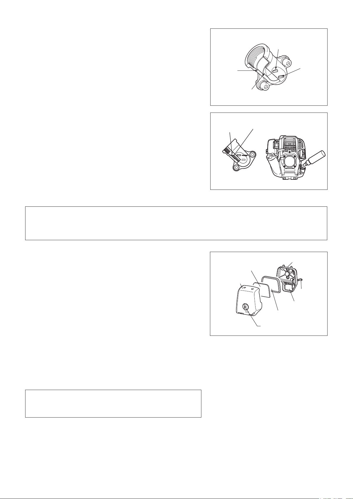
Cleaning the air cleaner
DANGER: Inammables strictly prohibited
Check and clean the air cleaner daily or every 10 operating hours.
Turn the choke lever fully to the close side, and keep the carburetor free from dust or dirt.
Loosen air cleaner cover mounting bolt. Remove the air cleaner cover. If oil adheres to the element (sponge), squeeze it rmly. If the elements are heavily contaminated: -
1) Remove the element (sponge), immerse it in warm water or in water diluted
neutral detergent, and dry it completely.
2) Clean the element (felt) with gasoline, and dry it completely.
Before attaching the elements, be sure to dry it completely. Insufcient drying of the element may lead to difcult startup.
Fit the element (sponge) into the element (felt). Fit the elements into the plate so that the sponge faces the air cleaner cover.
Wipe out oil adhering around the air cleaner cover and the breather part with waste cloth.
Immediately after cleaning is nished, attach the cleaner cover and tighten it with xing bolts. (In remounting, rst put the upper claw, and then the lower claw.)
Points in handling the air cleaner elements
Clean the elements several times a day, if excessive dust adheres to it. If operation continues with the elements remaining not cleared of oil, oil in the air cleaner may fall outside, resulting in oil contamination.
Element
(sponge)
Air cleaner
cover
Plate
Choke lever
Breather part
Element (felt)
Fixing bolt
19
Page 20
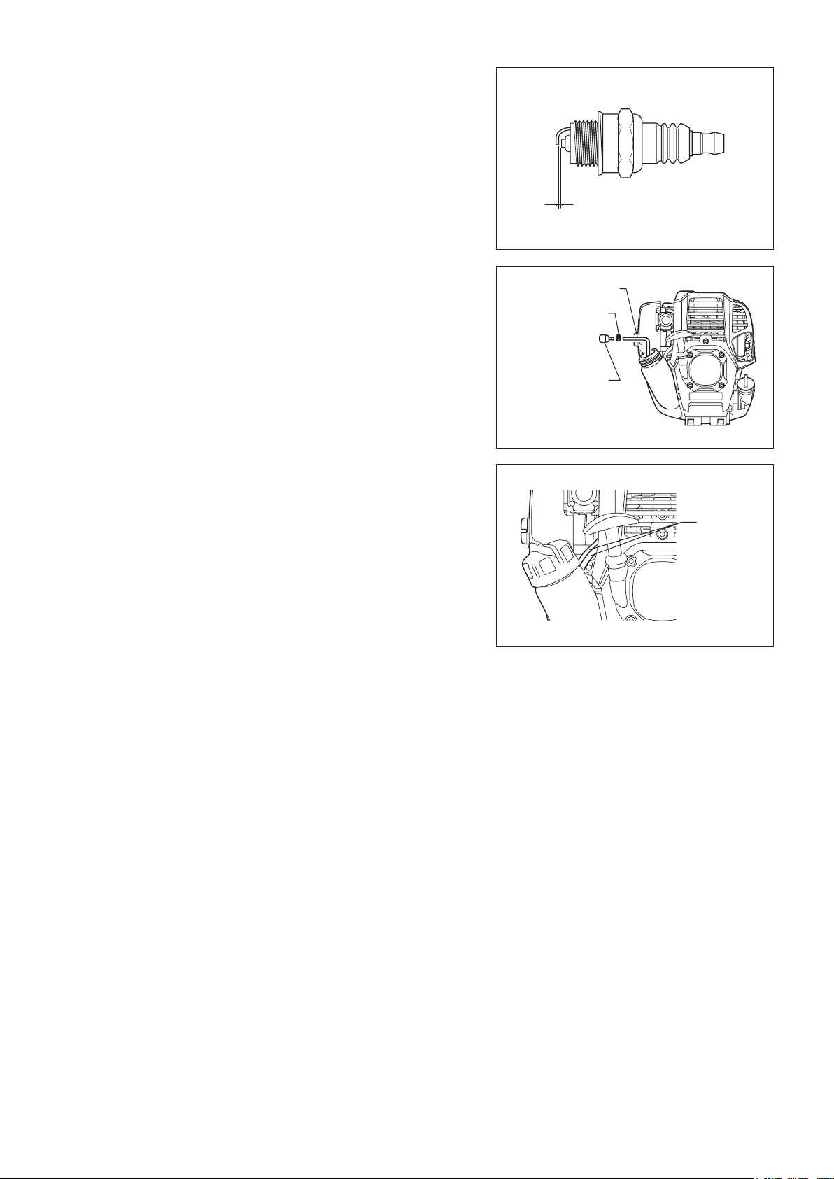
CHECKING THE SPARK PLUG
Only use the supplied universal wrench to remove or to install the spark plug. The gap between the two electrodes of the spark plug should be 0.7 - 0.8 mm -
(0.028” - 0.032”). If the gap is too wide or too narrow, adjust it. If the spark plug is
clogged or contaminated, clean it thoroughly or replace it.
CAUTION: Never touch the spark plug connector while the engine is running
(danger of high voltage electric shock).
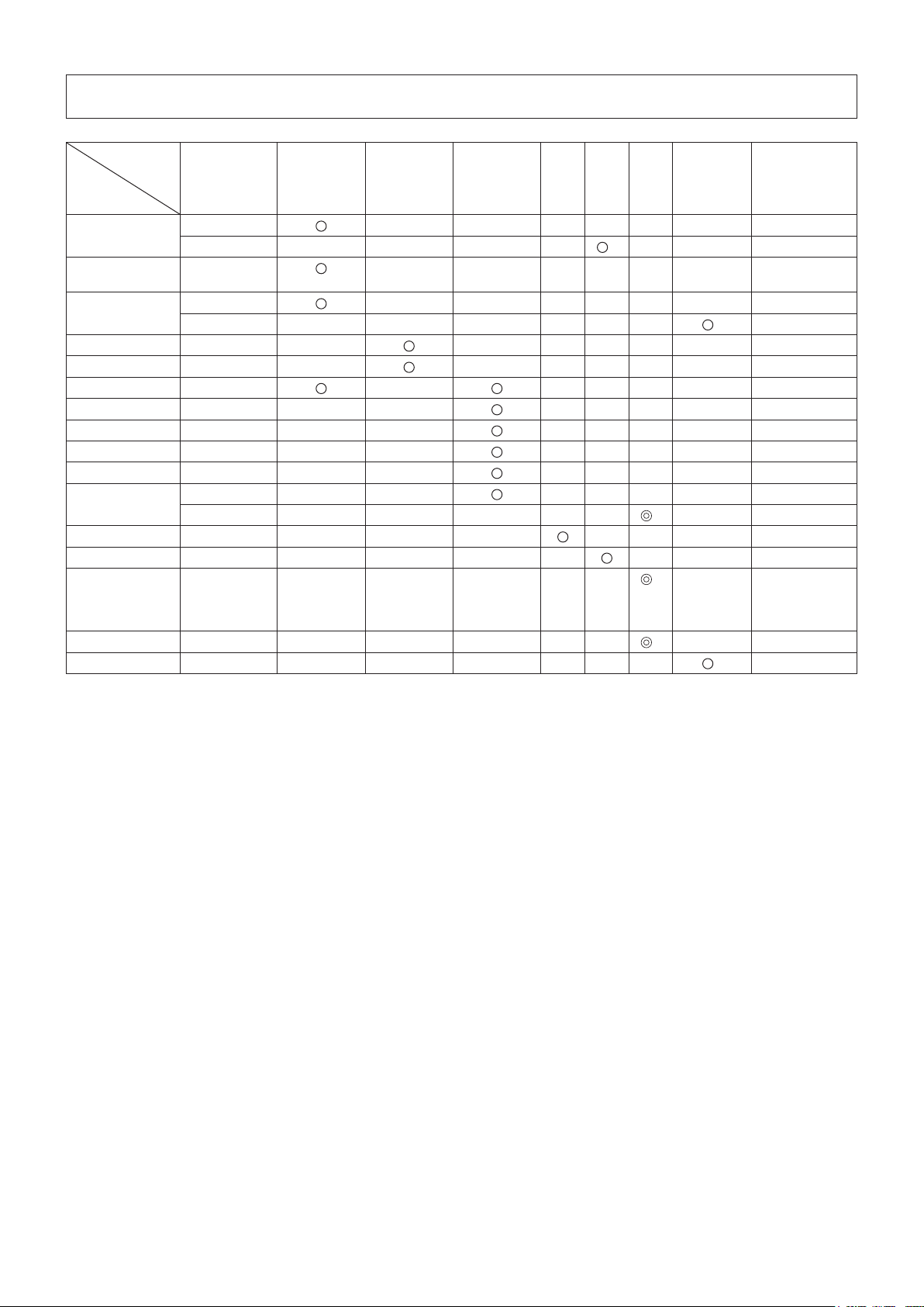
Cleaning the fuel lter (suction head in the fuel tank)
WARNING: INFLAMMABLES STRICTLY PROHIBITED
Check and clean the fuel lter monthly or every 50 operating hours.
The fuel lter (1) of the suction head is used to lter the fuel required by the -
carburetor.
Visually check the fuel lter regularly. To check the felt lter, open the tank cap, use a wire hook and pull out the suction head through the tank opening. Replace
the felt lter if it has hardened, been contaminated or be clogged.
Replace the felt lter at least quarterlyto ensure an enough fuel supply to the carburetor. Otherwise an insufcient fuel supply will cause the engine start failure
and limited maximum speed.
Replacing the fuel pipe
CAUTION: Inammables strictly prohibited
Check and clean the fuel pipe daily or every 10 operating hours.
Replace the fuel pipe every 200 operating hours or every year regardless of
operating frequency. Otherwise fuel leakage may lead to re.
If you nd any leakage during inspection, replace the oil pipe immediately.
0.7 mm - 0.8 mm
(0.028” - 0.032”)
Fuel pipe
Hose clamp
Fuel lter (1)
Fuel pipe
INSPECTION OF BOLTS, NUTS AND SCREWS
Retighten loose bolts, nuts, etc. Check for fuel and oil leakage. Replace damaged parts with new ones for safety operation. -
CLEANING OF PARTS
Keep engine clean by wiping down with a cloth rag. Keep the cylinder ns free of dust or dirt. Dust or dirt adhering to the ns will cause piston seizure.
REPLACEMENT OF GASKETS AND PACKINGS
Replace gaskets and packings if the engine is disassembled.
For any maintenance or adjustment not described in this manual, ask your local
MAKITA authorized service center.
20
Page 21

STORAGE
WARNING: When draining the fuel, stop the engine and wait for the engine
to cool down.
Failure to do so may cause burns or re.
ATTENTION: When you store the machine for a long time, drain all fuel from
the fuel tank and carburetor, and keep it at a dry and clean place.
Drain fuel from the fuel tank and carburetor according to the following procedure: -
1) Remove the fuel tank cap, and drain fuel completely.
If there is any foreign materials remaining in the fuel tank, remove it completely.
2) Pull out the fuel lter from the rell port using a wire.
3) Push the primer pump until fuel is drained from there, and drain fuel coming into
the fuel tank.
4) Reset the lter to the fuel tank, and securely tighten the fuel tank cap.
5) Then, continue to operate the engine until it stops.
Remove the spark plug, and drip several drops of engine oil through the spark plug hole.
Gently pull the starter handle so that engine oil will spread over the engine, and attach the spark plug.
Attach the cover to the cutting blades. During storage, keep the rod horizontal or keep the machine upright with the blade edge oriented upward. (In this case, pay full attention to prevent the
machine from falling.)
Never store the machine with the cutting blade edge oriented downward. Lubricating oil may spill out.
Keep the drained fuel in a special container in a well-ventilated shade. -
Drain fuel
Humidity
21
Page 22
Attention after long-time storage
Before startup after long-time shutdown, be sure to replace oil (refer to P18). Oil will deteriorate while the machine is kept out of operation. -
Operating
time
Before
operation
After
lubrication
Daily
(10h)
15h 50h 200h
Item
Engine oil Inspect/clean
Replace
Tightening parts
Inspect
(bolt, nut)
Fuel tank Clean/inspect
Drain fuel
Throttle lever Check function
Stop switch Check function
Cutting blades Inspect
Low-speed rotation Inspect/adjust
Air cleaner Clean
Ignition plug Inspect
Cooling air duct Clean/inspect
Fuel pipe Inspect
Replace
Gear-case grease Rell
Fuel lter Clean/replace
Clearance between
Adjust
air intake valve
and air discharge
valve
Engine overhaul
Carburetor Drain fuel
*1 Perform initial replacement after 20h operation.
*2 For the 200 operating hour inspection, request Authorized Service Agent or a machine shop.
*3 After emptying the fuel tank, continue to run the engine and drain fuel in the carburetor.
Shutdown/
rest
Corresponding
P
10
1
*
18
20
-
3
*
21
-
14
12
14
19
20
20
20
2
*
17
20
2
*
2
*
3
*
-
21
22
Page 23

TROUBLESHOOTING
Before making a request for repairs, check a trouble for yourself. If any abnormality is found, control your machine according to the description
of this manual. Never tamper or dismount any part contrary to the description. For repairs, contact Authorized Service Agent or local dealership.
State of abnormality Probable cause (malfunction) Remedy
Failure to operate primer pump Push 7 to 10 times
Low pulling speed of starter rope Pull strongly
Lack of fuel Feed fuel
Clogged fuel lter Clean
Broken fuel tube Straighten fuel tube
Engine does not start
Engine stops soon
Engine speed does not increase
Cutting blade does not move
Stop engine immediately
Main unit vibrates abnormally
Stop engine immediately
Cutting blades do not stop immediately
Stop engine immediately
Deteriorated fuel Deteriorated fuel makes starting more difcult.
Excessive suction of fuel Set throttle lever from medium speed to high
Detached plug cap Attach securely
Contaminated spark plug Clean
Abnormal clearance of spark plug Adjust clearance
Other abnormality of spark plug Replace
Abnormal carburetor Make request for inspection and maintenance.
Starter rope cannot be pulled Make request for inspection and maintenance.
Abnormal drive system Make request for inspection and maintenance.
Insufcient warm-up Perform warm-up operation
Choke lever is set to “
warmed up.
Clogged fuel lter Clean
Contaminated or clogged air cleaner Clean
Abnormal carburetor Make request for inspection and maintenance.
Abnormal drive system Make request for inspection and maintenance.
Loosened cutting blades-tightening nut Tighten securely
Twigs caught by cutting blades. Remove foreign matter
Abnormal drive system Make request for inspection and maintenance.
Broken, bent or worn cutting blades Replace cutting blades
Loosened cutting blades-tightening nut Tighten securely
Abnormal drive system Make request for inspection and maintenance.
High idling rotation Adjust
Detached throttle wire Attach securely
Abnormal drive system Make request for inspection and maintenance.
” although engine is
Replace with new one. (Recommended
replacement: 1 month)
speed, and pull starter handle until engine
starts. Once engine starts, cutting blades
start moving. Pay full attention to cutting
blades.
If engine will not start still, remove spark plug,
make electrode dry, and reassemble them as
they originally are. Then, start as specied.
Set to “ ”
Engine does not stop
Run engine at idling, and set choke lever
to “
”
When the engine does not start after warm-up operation:
If there is no abnormality found for the check items, open the throttle by about 1/3 and start the engine.
Detached connector Attach securely
Abnormal electric system Make request for inspection and maintenance.
23
Page 24

AIR INDEX
An Air Index Information hang tag was supplied to this engine in accordance with the emission
regulations of the California Air Resources Board.
The bar graph on the hang tag shows the emissions performance of this engine.
The bar graph can be used to compare the emissions performance with other available engine.
The lower the Air Index, the less pollution.
The following durability description is to provide you with information relating to the emission
durability period of the engine.
Descriptive Term Applicable to Emissions Durability Period
Moderate – 50 hours (0-65 cc)
Intermediate – 125 hours (0-65 cc)
Extended – 300 hours (0-65 cc)
Notice: The Air Index Information hang tag must remain on the engine or on the equipment until
it is sold to the ultimate purchaser. Remove the hang tag before operating the engine.
24
Page 25

CALIFORNIA EMISSIONS CONTROL WARRANTY STATEMENT
YOUR WARRANTY RIGHTS AND OBLIGATIONS
The California Air Resources Board and Makita USA, Inc are pleased to explain the emissions control system’s
warranty on your 2007 and later small off-road engine. In California, new equipment that use small off-engines must
be designed, built, and equipped to meet the State’s stringent anti-smog standards. Makita USA, Inc must warrant
the emissions control system on your small off-road engine for the period listed below provided there has been no
abuse, neglect or improper maintenance of your equipment.
Your emissions control system may include parts such as: carburetors or fuel injection system, ignition system,
catalytic converters, fuel tanks, valves, lters, clamps, connectors, and other associated components. Also,
included may be hoses, belts, connectors, sensors, and other emission-related assemblies.
Where a warrantable condition exists, Makita USA, Inc will repair your small off-road engine at no cost to you
including diagnosis, parts and labor.
MANUFACTURER’S WARRANTY COVERAGE:
This emissions control system is warranted for two years. If any emissions-related part on your equipment is
defective, the part will be repaired or replaced by Makita USA, Inc.
OWNER’S WARRANTY RESPONSIBILITIES:
• As the small off-road engine owner, you are responsible for performance of the required maintenance listed in
your owner’s manual. Makita USA, Inc recommends that you retain all receipts covering maintenance on your
small off-road engine, but Makita USA, Inc cannot deny warranty solely for the lack of receipts or your failure to
ensure the performance of all scheduled maintenance.
• As the small off-road engine owner, you should however be aware that Makita USA, Inc may deny you warranty
coverage if your small off-road engine or a part has failed due to abuse, neglect, or improper maintenance or
unapproved modications.
• You are responsible for presenting your small off-road engine to a Makita Factory Service Center as soon as
the problem exists. The warranty repairs should be completed in a reasonable amount of time, not to exceed 30
days. If you have a question regarding your warranty coverage, you should contact:
* For the nearest Makita service center, please visit www.makitatools.com
* For technical support or questions regarding operation of our tools and accessories call:
1-800-4-MAKITA
* Makita USA Inc. Corporate Ofce: 14930 Northam St. La Mirada, CA 90638-5753
DEFECTS WARRANTY REQUIREMENTS:
(a) The warranty period begins on the date the engine or equipment is delivered to an ultimate purchaser.
(b) General Emissions Warranty Coverage. Makita USA, Inc must warrant to the ultimate purchaser and each
subsequent owner that the engine or equipment is:
(1) Designed, built, and equipped so as to conform with all applicable regulations adopted by the Air Resources
Board; and
(2) Free from defects in materials and workmanship that causes the failure of a warranted part for a period of
two years.
(c) The warranty on emissions-related parts will be interpreted as follows:
25
Page 26

(1) Any warranted part that is not scheduled for replacement as required maintenance in the written
instructions required by subsection (d) must be warranted for the warranty period dened in Subsection
(b) (2). If any such part fails during the period of warranty coverage, it must be repaired or replaced by the
manufacturer according to Subsection (4) below. Any such part repaired or replaced under the warranty
must be warranted for the remaining warranty period.
(2) Any warranted part that is scheduled only for regular inspection in the written instructions required by
subsection (d) must be warranted for the warranty period dened in Subsection (b) (2). A statement in such
written instructions to the effect of “repair or replace as necessary” will not reduce the period of warranty
coverage. Any such part repaired or replaced under warranty must be warranted for the remaining warranty
period.
(3) Any warranted part that is scheduled for replacement as required maintenance in the written instructions
required by subsection (d) must be warranted for the period of time prior to the rst scheduled replacement
point for that part. If the part fails prior to the rst scheduled replacement, the part must be repaired or
replaced by the engine manufacturer according to Subsection (4) below. Any such part repaired or replaced
under warranty must be warranted for the remainder of the period prior to the rst scheduled replacement
point for the part.
(4) Repair or replacement of any warranted part under the warranty must be performed at no charge to the
owner at a warranty station.
(5) Notwithstanding the provisions of Subsection (4) above, warranty services or repairs must be provided at all
manufacturer distribution centers that are franchised to service the subject engines.
(6) The owner must not be charged for diagnostic labor that leads to the determination that a warranted part is
in fact defective, provided that such diagnostic work is performed at a warranty station.
(7) The manufacturer is liable for damages to other engine components proximately caused by a failure under
warranty of any warranted part.
(8) Throughout the emissions warranty period dened in Subsection (b) (2), the manufacturer must maintain a
supply of warranted parts sufcient to meet the expected demand for such parts.
(9) Any replacement part may be used in the performance of any warranty maintenance or repairs and
must be provided without charge to the owner. Such use will not reduce the warranty obligations of the
manufacturer.
(10)
Add on or modied parts that are not exempted by the Air Resources Board may not be used. The use
of any non exempted add on or modied parts will be grounds for disallowing a warranty claim. The
manufacturer will not be liable to warrant failures of warranted parts caused by the use of a non exempted
add on or modied part.
(11)
The manufacturer issuing the warranty shall provide any documents that describe that manufacturer’s
warranty procedures or policies within ve working days of request by the Air Resources Board.
(d) Emission Warranty Parts List.
(1) Fuel Metering System
(i) Carburetor and internal parts
(ii) Fuel Filter
(iii) Fuel Tank.
(2) Air Induction System
(i) Air cleaner plate (including choke system)
(ii) Air cleaner cover
(iii) Air cleaner element
(3) Ignition System
(i) Spark Plugs.
(ii) Magneto or electronic ignition system.
(iii) Spark advance/retard system.
(4) Miscellaneous Items Used in Above Systems
(i) Hoses, Sealing gaskets, belts, connectors, and assemblies.
26
Page 27

Makita USA, Inc will furnish with each new engine written instructions for the maintenance and use of the engine
by the owner.
(e) MAINTENANCE STATEMENTS
It is your responsibility to have all scheduled inspection and maintenance services performed at the times
recommended in the 2007 and later Owner’s Manual and to retain proof that inspection and maintenance
services are performed at the times when recommended. Makita USA, Inc will not deny a warranty claim solely
because you have no record of maintenance; however, Makita USA, Inc may deny a warranty claim if your
failure to perform required maintenance resulted in the failure of warranted part. The proof, which you maintain,
should be given to each subsequent owner of the engine. You are responsible for performing the scheduled
maintenance described below based on the procedures specied in the 2007 and later Owner’s Manual. The
scheduled maintenance below is based on the normal engine-operating schedule.
PROCEDURE INTERVAL
1) Clean engine and check bolts and nuts. Retighten if
necessary.
2) Check and rell engine oil (4 stroke engine only) : Every 8 hours (rell daily up to upper limit)
3) Change engine oil (4 stroke engine only) : Initial 20 hours and every 50 hours afterward
4) Check clogging of cooling air passage and cylinder
ns. Remove and clean if necessary.
5) Clean air cleaner. : Every 8 hours (daily)
6) Check spark plug. Clean and adjust if necessary. : Every 8 hours (daily)
7) Check mufer exhaust outlet (or port). Clean if
necessary.
8) Check fuel lter. If clogged, replace with new one. : Every 50 hours (monthly)
9) Adjust valve clearance, if applicable (4 stroke
engine only).
10) Replace fuel lines. : Every 200 hours (yearly)
11) Clean and inspect the complete engine. Replace
any damaged or worn out parts.
12) Replace packings and gaskets with new ones. : Every reassembling
: Every 8 hours (daily)
: Every 8 hours (daily)
: Every 50 hours (monthly)
: Every 200 hours (yearly)
: Every 200 hours
27
Page 28

FEDERAL EMISSION COMPONENT DEFECT WARRANTY
EMISSION COMPONENT DEFECT WARRANTY COVERAGE - This emission warranty is applicable in all States,
except the State of California
Makita U.S.A., Inc., (herein “Makita”) warrant to the initial retail purchaser and each subsequent owner, that this
utility equipment engine (herein “engine”) was designed, built, and equipped to conform at the time of initial sale to
all applicable regulations of the U.S. Environmental Protection Agency (EPA), and that the engine is free of defects
in materials and workmanship which would cause this engine to fall to conform with EPA regulations during its
warranty period.
For the components listed under PARTS COVERED, the dealer or service center authorized by Makita will, at no
cost to you, make the necessary diagnosis, repair, or replacement necessary to ensure that the engine complies
with applicable U.S. EPA regulations.
EMISSION COMPONENT DEFECT WARRANTY PERIOD
The warranty period for this engine begins on the date of sale to the initial purchaser and continues for a period of
2 years.
PARTS COVERED
Listed below are the parts covered by the Emission Component Defect Warranty. Some of the parts listed below
may require scheduled maintenance and are warranted up to the rst scheduled replacement point for that part.
1) Fuel Metering System
(i) Carburetor and internal parts
(ii) Fuel lter, if applicable
(iii) Throttle stopper, if applicable
(iv) Choke System, if applicable
2) Air Induction System
(i) Air cleaner plate
(ii) Air cleaner case
(iii) Air cleaner element
3) Ignition System
(i) Spark plug
(ii) Flywheel Magneto
(iii) Ignition Coil
4) Miscellaneous Items Used in Above
Systems
(i) Fuel hoses, clamps and sealing
gaskets
28
Page 29

OBTAINING WARRANTY SERVICE
To obtain warranty service, take your engine to the nearest MAKITA Factory Service Center authorized by
MAKITA. Bring your sales receipts indicating date of purchase for this engine. The dealer or service center
authorized by Makita will perform the necessary repairs or adjustments within a reasonable amount of time and
furnish you with a copy of the repair order. All parts and accessories replaced under this warranty become the
property of Makita.
WHAT IS NOT COVERED
* Conditions resulting from tampering, misuse, improper adjustment (unless they were made by the dealer
or service center authorized by Makita during a warranty repair), alteration, accident, failure to use the
recommended fuel and oil, or not performing required maintenance services.
* The replacement parts used for required maintenance services.
* Consequential damages such as loss of time, inconvenience, loss of use of the engine of equipment, etc.
* Diagnosis and inspection charges that do not result in warranty-eligible service being performed.
* Any non-authorized replacement part, or malfunction of authorized parts due to use of non-authorized parts.
OWNER’S WARRANTY RESPONSIBILITIES
As the engine owner, you are responsible for the performance of the required maintenance listed in your owner’s
manual, Makita recommends that you retain all receipts covering maintenance on your engine, but Makita can
not deny warranty solely for the lack of receipts or for your failure to ensure the performance of all scheduled
maintenance.
As the engine owner, you should however be aware that the Makita may deny your warranty coverage if your
engine or a part has failed due to abuse, neglect, improper maintenance or unapproved modications.
You are responsible for presenting your engine to the nearest dealer or service center authorized by Makita when a
problem exists.
If you have any questions regarding your warranty rights and responsibilities, you should contact the Followings:
* For the nearest Makita service center, please visit www.makitatools.com
* For technical support or questions regarding operation of our tools and accessories call: 1-800-4-MAKITA
* Makita USA Inc. Corporate Ofce: 14930 Northam St. La Mirada, CA 90638-5753
(For Canada)
* For the authorized service center nearest you please refer to the local yellow pages directory under “tools”, or
contact our customer service department Tel 1-800-263-3734 (Canada only), or visit our web site www.makita.ca
* Makita Canada Inc. Head Ofce & Plant: 1950 Forbes Street, Whitby, ON L1N7B7.
29
Page 30

THINGS YOU SHOULD KNOW ABOUT THE EMISSION CONTROL SYSTEM WARRANTY
MAINTENANCE AND REPAIRS
You are responsible for the proper use and maintenance of the engine. You should keep all receipts and
maintenance records covering the performance of regular maintenance in the event questions arise. These receipts
and maintenance records should be transferred to each subsequent owner of the engine. Makita reserves the
rights to deny warranty coverage if the engine has not been properly maintained. Warranty claims will not be
denied, however, solely because of the lack of required maintenance or failure to keep maintenance records.
MAINTENANCE, REPLACEMENT OR REPAIR OF EMISSION CONTROL DEVICES AND
SYSTEMS MAY BE PERFORMED BY ANY REPAIR ESTABLISHMENT OR INDIVIDUAL;
HOWEVER, WARRANTY REPAIRS MUST BE PERFORMED BY A DEALER OR SERVICE
CENTER AUTHORIZED BY Makita. THE USE OF PARTS THAT ARE NOT EQUIVALENT
IN PERFORMANCE AND DURABILITY TO AUTHORIZED PARTS MAY IMPAIR THE
EFFECTIVENESS OF THE EMISSION CONTROL SYSTEM AND MAY HAVE A BEARING ON
THE OUTCOME OF A WARRANTY CLAIM.
If other than the parts authorized by Makita are used for maintenance replacements or for the repair of components
affecting emission control, you should assure yourself that such parts are warranted by their manufacturer to be
equivalent to the parts authorized by Makita in their performance and durability.
HOW TO MAKE A CLAIM
All repairs qualifying under this limited warranty must be performed by a service dealer authorized by MAKITA.
In the event that any emission-related part is found to be defective during the warranty period, you shall notify
MAKITA at the following contacts and you will be advised of the appropriate warranty service dealer or
service providers where the warranty repair can be performed.
* For the nearest Makita service center, please visit www.makitatools.com
* For technical support or questions regarding operation of our tools and accessories call: 1-800-4-MAKITA
* Makita USA Inc. Corporate Ofce: 14930 Northam St. La Mirada, CA 90638-5753
(For Canada)
* For the authorized service center nearest you please refer to the local yellow pages directory under “tools”, or
contact our customer service department Tel 1-800-263-3734 (Canada only), or visit our web site www.makita.ca
* Makita Canada Inc. Head Ofce & Plant: 1950 Forbes Street, Whitby, ON L1N7B7.
30
Page 31

Français
(Mode d’emploi original)
Nous vous remercions d’avoir choisi le taille-haie thermique sur
perche MAKITA. Nous sommes heureux de vous proposer un
produit qui est le fruit d’un long programme de développement et de
nombreuses années de connaissances et d’expérience.
Pour obtenir en toute sécurité les meilleurs résultats possibles
de votre taille-haie thermique sur perche MAKITA, veuillez lire
attentivement ce manuel avant d’utiliser la machine et suivre toutes
les instructions qu’il contient an de garantir une utilisation correcte
du taille-haie thermique sur perche MAKITA.
Sommaire Page
PICTOGRAMMES ..........................................................................31
CONSIGNES DE SÉCURITÉ ......................................................... 32
DONNÉES TECHNIQUES .............................................................36
DÉSIGNATION DES PIÈCES ........................................................37
FIXATION DE L’UNITÉ DE COUPE À LA PERCHE ......................38
ESSENCE/REMPLISSAGE DU RÉSERVOIR ...............................39
PRÉCAUTIONS AVANT DE DÉMARRER LE MOTEUR ................ 41
UTILISATION DU TAILLE-HAIE THERMIQUE SUR PERCHE ...... 44
ENTRETIEN ...................................................................................45
ENTREPOSAGE ............................................................................50
DÉPANNAGE .................................................................................52
PICTOGRAMMES
Veuillez faire attention aux pictogrammes suivants lors de la lecture de ce manuel d’instructions
AVERTISSEMENT/DANGER Risque de pincement
Avant utilisation, lire attentivement et
comprendre la totalité des instructions
contenues dans ce manuel
INTERDICTION Carburant (essence)
Défense de fumer
Flammes nues interdites Arrêt d’urgence
Porter des chaussures de sécurité Premiers soins
Porter des gants de protection MARCHE/DÉMARRAGE
Faire attention aux lignes électriques,
risque de choc électrique
Démarrage manuel du moteur
ARRÊT/COUPURE MACHINE
Zone de travail interdite aux individus et
aux animaux
Porter un casque de protection ainsi que
des protections oculaire et auditive
31
Page 32

CONSIGNES DE SÉCURITÉ
Consignes générales
Avant utilisation, lisez attentivement ce manuel et apprenez à manipuler correctement le taille-haie thermique sur perche. CET ÉQUIPEMENT PEUT
ENTRAÎNER DES BLESSURES GRAVES S’IL EST UTILISÉ DE MANIÈRE
INCORRECTE!
Lorsque vous prêtez le taille-haie thermique sur perche à une autre personne, fournissez-lui toujours des instructions détaillées sur l’utilisation correcte de
l’appareil. Assurez-vous que le manuel d’instructions est fourni avec le taille-haie
thermique sur perche.
Les utilisateurs inexpérimentés doivent demander des instructions de base au -
vendeur an de se familiariser avec la manipulation du taille-haie thermique sur
perche.
Conservez ce manuel dans un endroit facile d’accès pour vous y reporter facilement.
N’autorisez pas les personnes de moins de 18 ans à utiliser le taille-haie thermique sur perche. Les personnes âgées de plus de 16 ans peuvent toutefois
utiliser le taille-haie thermique sur perche en vue d’apprentissage si elles sont
toujours sous la surveillance d’un adulte sachant utiliser la machine.
Utilisez toujours le taille-haie thermique sur perche avec le maximum de soin et d’attention.
Utiliser le taille-haie thermique sur perche dans les conditions suivantes peut entraîner de graves blessures. N’utilisez pas le taille-haie thermique sur perche :
si vous vous sentez fatigué ou malade;•
après avoir consommé de l’alcool et/ou des médicaments;•
la nuit ou avec un faible éclairage;•
si vous êtes enceinte.•
Utilisation normale
Ce taille-haie thermique sur perche est conçu exclusivement pour tailler les buissons et les haies dont les branches ne dépassent pas un diamètre de 7 mm.
Il ne doit en aucun cas être utilisé dans un autre but.
Équipement de protection personnel
La tenue portée doit être fonctionnelle, bien ajustée et ne pas entraver vos mouvements.
Ne portez pas de bijoux ni de vêtements qui pourraient s’accrocher dans les
sous-bois ou la machine.
Pour une protection adaptée contre les blessures à la tête, aux yeux, aux pieds, aux mains et contre les pertes auditives, l’équipement et les vêtements de
protection suivants doivent être portés lors de l’utilisation du taille-haie thermique
sur perche.
Pour éviter les blessures à la tête ou aux yeux, portez toujours un casque de protection (1) avec des lunettes ou une visière (2).
Pour éviter toute perte auditive, portez toujours un casque anti-bruit (3) adapté. Il est vivement recommandé à l’utilisateur de porter une combinaison de travail -
ajustée (4).
Portez toujours des gants de travail en cuir résistants (5) lorsque vous utilisez le taille-haie thermique sur perche.
Lorsque vous utilisez le taille-haie thermique sur perche, portez toujours des chaussures renforcées (6) dotées d’une semelle antidérapante. Des chaussures
de sécurité spéciales vous garantissent une bonne stabilité et vous protègent
contre les blessures.
32
Page 33

Démarrage du taille-haie thermique sur perche
Un périmètre de sécurité d’un diamètre de 15 mètres autour de la zone de travail doit toujours être maintenu.
Assurez-vous qu’aucune personne (en particulier des enfants) ni aucun animal
ne pénètre dans ce périmètre. En règle générale, évitez d’utiliser le taille-haie
sur perche lorsque d’autres personnes (en particulier des enfants) se trouvent à
proximité.
Avant de démarrer le taille-haie thermique sur perche, vériez toujours que la machine est en bon état de marche.
Vériez le bon fonctionnement du mécanisme de sécurité du levier d’accélérateur. Le levier de sécurité doit pouvoir être actionné facilement sans
forcer. Assurez-vous du bon fonctionnement du levier de sécurité. Vériez que
les poignées sont propres et sèches et que le commutateur d’arrêt fonctionne
correctement.
Suivez toujours les instructions indiquées dans ce manuel pour démarrer le taillehaie thermique sur perche.
Suivez les instructions ci-dessous pour démarrer le taille-haie
thermique sur perche
Ne démarrez le taille-haie thermique sur perche que lorsque la machine est -
totalement montée et que tous les accessoires sont xés.
Avant de démarrer le moteur, assurez-vous que des objets étrangers tels que des pierres, des branches, etc. ne sont pas coincés dans les lames de coupe.
Coupez le moteur immédiatement s’il présente un problème. Pendant l’utilisation, tenez fermement les poignées avant et arrière. Les poignées doivent être propres et n’avoir aucune trace d’humidité, de résine, d’huile ou de
graisse.
Assurez-vous toujours de votre stabilité.
N’utilisez le taille-haie thermique sur perche qu’à l’extérieur. Coupez toujours le moteur immédiatement et interrompez votre travail si le moteur présente un problème ou si la machine fait un bruit inhabituel.
Les gaz d’échappement sont toxiques. N’utilisez jamais la machine dans une pièce fermée ou un tunnel sans ventilation (risque de suffocation et d’asphyxie
au gaz). Notez que le monoxyde de carbone est un gaz inodore. Assurez-vous
toujours que les endroits où la machine est utilisée sont sufsamment ventilés.
Coupez le moteur lorsque vous faites une pause ou lorsque vous laissez le taille- haie thermique sur perche sans surveillance. Placez la machine dans un endroit
sûr et assurez-vous qu’aucun matériau combustible ne se trouve à proximité.
Ne posez jamais le taille-haie chaud sur de l’herbe sèche ou sur un matériau combustible.
Pour réduire les risques d’incendie, veillez à ce qu’il n’y ait ni débris, ni feuilles, ni -
un excès de lubriant sur le moteur et le silencieux.
Ne faites jamais fonctionner le moteur si le silencieux est défectueux. Coupez le moteur avant de transporter la machine. Coupez toujours le moteur dans les situations suivantes. Lorsque : -
vous faites une pause;•
vous transportez la machine;•
vous nettoyez la machine;•
vous remplissez le réservoir de la machine;•
vous effectuez des opérations d’entretien sur la machine;•
vous réparez un problème sur la machine.•
Lorsque vous transportez la machine dans un véhicule, attachez toujours fermement le taille-haie thermique sur perche pour éviter toute fuite de carburant
résiduel.
Vidangez toujours le réservoir d’essence avant de transporter le taille-haie thermique sur perche dans un véhicule.
Lorsque vous déchargez la machine d’un véhicule, faites attention à ne pas la laisser tomber car cela pourrait endommager gravement le réservoir.
Sauf en cas d’urgence, ne laissez jamais tomber le taille-haie thermique sur perche car cela pourrait l’endommager.
Pause Transport de la machine Nettoyage de la machine Remplissage du réservoir Opérations d’entretien sur la -
machine
Réparation d’un problème -
sur la machine
33
Page 34

Lorsque vous transportez le taille-haie thermique sur perche, soulevez toujours complètement la machine du sol. Ne traînez jamais la machine sur le sol car cela
pourrait endommager le réservoir d’essence et causer un incendie.
Utilisez toujours le couvercle de la lame fourni pour protéger et sécuriser le dispositif de coupe du taille-haie thermique sur perche lors du transport et de
l’entreposage.
Remplissage du réservoir
Avant de remplir le réservoir, coupez le moteur. Ne remplissez jamais le réservoir à proximité de ammes nues. Ne fumez pas lors du remplissage du réservoir. Laissez toujours sufsamment de temps au moteur pour refroidir avant de remplir le réservoir.
Veillez à ce que votre peau n’entre pas en contact avec des produits pétroliers. N’inhalez pas les vapeurs d’essence et portez toujours des gants de protection
lorsque vous remplissez le réservoir. Changez et nettoyez votre équipement de
protection à intervalles réguliers.
Veillez tout particulièrement à ne pas renverser de l’essence ou de l’huile an de ne pas contaminer les sols. Si de l’essence ou de l’huile a été renversée sur le
taille-haie, essuyez immédiatement sa surface avec un chiffon. Faites sécher les
chiffons utilisés pour essuyer l’essence dans un endroit bien ventilé avant de les
jeter. Autrement, il y a risque de combustion spontanée.
Assurez-vous que l’essence n’entre pas en contact avec vos vêtements. Les vêtements souillés par de l’essence doivent être changés immédiatement (risque
d’incendie).
Replacez le bouchon du réservoir d’essence et serrez-le fermement. Pour démarrer le moteur, déplacez le taille-haie thermique sur perche à au moins
3 mètres du lieu de remplissage du réservoir.
Vériez régulièrement que le bouchon du réservoir d’essence est bien fermé. Ne remplissez jamais le réservoir de la machine dans une pièce fermée. Les vapeurs d’essence s’accumulent au ras du sol (risque d’explosion).
Conservez l’essence dans des conteneurs appropriés uniquement et assurez- vous qu’elle est hors de portée des enfants.
3 m
Fonctionnement
Pendant l’utilisation du taille-haie thermique sur perche, tenez toujours la machine avec les deux mains.
N’utilisez le taille-haie thermique sur perche que dans de bonnes conditions de visibilité et d’éclairage. Pendant les saisons froides, faites attention aux sols
glissants et aux zones humides (glace et neige) (risque de glissade) et assurezvous toujours de votre stabilité.
N’utilisez jamais le taille-haie thermique sur perche sur des sols instables ou des terrains en pente.
N’utilisez jamais le taille-haie thermique sur perche en vous tenant sur une échelle.
Ne montez jamais dans un arbre pour réaliser des opérations de coupe à l’aide du taille-haie thermique sur perche.
Pour réduire les risques de trébuchement ou de chute, ne reculez pas en utilisant le taille-haie thermique sur perche.
Coupez toujours le moteur avant de nettoyer ou de réparer la machine. Ne remplacez pas non plus de pièces avant l’arrêt du moteur.
N’utilisez pas le taille-haie thermique sur perche si l’unité de coupe est endommagée ou usée.
34
Page 35

Consignes d’entretien
Faites toujours de votre mieux pour produire le moins de pollution et de bruit possible lorsque vous utilisez le taille-haie thermique sur perche. Veillez à ce que
le carburateur soit bien réglé.
Nettoyez le taille-haie à intervalles réguliers et vériez périodiquement que tous les écrous et boulons sont bien serrés.
Ne réparez ou n’entreposez jamais le taille-haie thermique sur perche à proximité -
de ammes nues, d’étincelles, etc.
Vidangez le réservoir d’essence avant l’entreposage et rangez toujours le taille- -
haie thermique sur perche dans une pièce verrouillée sufsamment ventilée.
Assurez-vous que le taille-haie thermique sur perche est toujours hors de portée
des enfants.
An d’éviter d’endommager davantage le taille-haie thermique sur perche et/ou de vous blesser, ne réparez aucun dysfonctionnement de la machine
si vous n’êtes pas qualié pour le faire. Pour toute réparation, contactez
systématiquement votre vendeur ou un technicien agréé.
N’essayez pas de modier ou de transformer le taille-haie thermique sur perche car
cela pourrait altérer la sécurité d’utilisation.
Les travaux d’entretien réalisables par l’utilisateur se limitent à ceux décrits dans
le manuel d’instructions. Toutes les autres opérations doivent être réalisées par un
technicien agréé.
N’utilisez que des pièces de rechange et des accessoires d’origine fournis par
MAKITA via des services après-vente agréés.
L’utilisation d’accessoires et d’outils non agréés accroît le risque d’accident et de
blessures. MAKITA ne pourra être tenue pour responsable en cas d’accident ou de
dommages dus à l’utilisation d’accessoires et de pièces non agréés.
Premiers soins
Au cas où un accident surviendrait, assurez-vous qu’une trousse de premiers soins
complète est à portée de main.
Remplacez sans délai tout élément utilisé dans la trousse de premiers soins.
Si vous demandez de l’aide en cas d’urgence, donnez les
informations suivantes :
lieu de l’accident;•
conditions de l’accident;•
le nombre de blessés;•
la gravité des blessures;•
votre nom.•
35
Page 36

DONNÉES TECHNIQUES : EN5550SH
Modèle
EN5550SH
Poignée arceau
Dimensions (L x P x H) po (mm) 69-1/4” x 9-1/2” x 9-1/2” (1 760 mm x 243 mm x 241 mm)
Poids lb (kg) 14,1 (6,4)
Volume (réservoir d’essence) oz liq (l) 20,3 (0,6)
Longueur de coupe po (mm) 20-1/2” (520)
3
Cylindrée pouce cube (cm
Rendement maximal du moteur hp (kW) 1,1 à 7 000/min (0,77 à 7 000 min
) 1,5 (25,4)
-1
)
Course par minute 4 600
Consommation d’essence kg/h 0,33
Consommation d’essence spécique g/kWh 408
Vitesse au ralenti tr/min 3 000
Vitesse d’embrayage tr/min 4 400
Carburateur
(carburateur à membrane)
type WALBRO WYL
Système d’allumage type Allumage transistorisé
Bougie d’allumage type NGK CMR4A
Distance entre les électrodes po (mm) 1/32” (0,7-0,8)
Carburant Essence automobile
Huile moteur
SAE 10W-30 huile de classication API
classe SF ou supérieure (moteur automobile à 4 temps)
Rapport de transmission 1/4,25
36
Page 37

DÉSIGNATION DES PIÈCES
1
2
3
4
5
6
7
8
9
10
11
12
13
14
15
16
17
18
Désignation des pièces
1 Câble de commande des gaz
2 Levier de sécurité
3 Levier d’accélérateur
4 Commutateur d’arrêt
5 Poignée
6 Axe
7 Boîte de vitesses
8 Lame de coupe
9 Filtre à air
10 Bouchon du réservoir d’essence
37
11 Réservoir d’essence
12 Carter d’embrayage
13 Bougie d’allumage
14 Pompe d’amorçage
15 Silencieux
16 Lanceur à rappel
17 Poignée de démarrage
18 Couvercle de lame
Page 38

FIXATION DE L’UNITÉ DE COUPE À LA
40 mm
PERCHE
Important :
Assurez-vous que le moteur est coupé et retirez le bouchon de la bougie d’allumage
avant de monter le taille-haie thermique sur perche.
Portez des gants de protection!
Sécurisez les lames de coupe à l’aide du couvercle de lame fourni lorsque vous
xez l’unité de coupe à la perche.
Retirez le bouchon de l’axe. Desserrez la vis M5 x 12 et le boulon M5 x 25. Insérez l’axe dans le carter d’engrenage. -
Arbre d’entraînement
Vis M5 x 10
Axe
REMARQUE : Assurez-vous que l’axe est complètement inséré dans le carter
d’engrenage (environ 40 mm/1,57”).
Si vous avez des difcultés à insérer l’axe, pivotez légèrement
l’arbre d’entraînement à la main et essayez de nouveau.
Assurez-vous que l’axe est inséré correctement et serrez la vis M5 x 12 et le boulon M5 x 25.
Boulon M5 x 25
Bouchon
38
Page 39

ESSENCE/REMPLISSAGE DU RÉSERVOIR
AVANT UTILISATION
Inspection et remplissage de l’huile moteur
Procédez comme suit, une fois le moteur refroidi. Placez le moteur de niveau, retirez le bouchon d’huile (Fig. 1) et vériez si le niveau d’huile est entre les repères de limite supérieure et inférieure sur le tuyau d’huile (Fig. 2).
Rajoutez de l’huile jusqu’au repère de limite supérieure si le niveau est insufsant (proche du repère de limite inférieure) (Fig. 3). La zone entre les repères externes est transparente, le niveau d’huile à l’intérieur peut donc être contrôlé sans avoir à retirer le bouchon d’huile. Cependant, si le tuyau d’huile devient très sale, la visibilité peut être altérée et le niveau d’huile doit être comparé à la section crantée
à l’intérieur du tuyau d’huile.
Pour information, le temps de remplissage de l’huile est d’environ 10 heures (10 remplissages ou un remplissage de 10 réservoirs d’huile). Si l’huile change de couleur ou se mélange à des impuretés, changez-la. (Pour connaître la fréquence et la méthode de remplacement,
reportez-vous à la page 47)
Huile recommandée : SAE 10W-30 huile de classication API, classe SF ou supérieure (moteur automobile à 4 temps)
Quantité d’huile : environ 0,08 l
REMARQUE : Si le moteur n’est pas de niveau, l’huile peut se répandre dans le moteur et le remplissage peut être excessif.
Remarque 1 concernant le changement d’huile : « Bouchon d’huile »
Retirez la poussière ou les impuretés au niveau de l’orice de remplissage d’huile, puis détachez le bouchon d’huile. Veillez à ce que le bouchon d’huile n’entre pas en contact avec du sable ou de la poussière. Le sable ou la poussière adhérant au bouchon d’huile pourrait perturber la circulation de l’huile ou entraîner une usure des pièces moteur, provoquant des problèmes.
Fig. 1 Fig. 2 Tuyau d’huile Fig. 3
(1) Maintenez le moteur de niveau et détachez le bouchon d’huile.
Si vous mettez trop d’huile, elle peut être souillée ou s’enammer en dégageant une fumée blanche.
Bouchon d’huile
Section crantée
interne (limite
supérieure)
Section crantée
interne (limite
inférieure)
Tuyau d’huile
Repère externe
(limite supérieure)
Repère externe
(limite inférieure)
Remplissez
avec de l’huile
jusqu’à atteindre
la section crantée
interne (limite
supérieure).
La zone entre la limite
externe supérieure et la
limite externe inférieure est
transparente, le niveau d’huile
peut donc être comparé à ces
repères depuis l’extérieur.
(2) Remplissez d’huile jusqu’au repère de limite supérieure. (voir Fig. 3)
Utilisez la bouteille d’huile pour effectuer le remplissage.
(3) Serrez bien le bouchon d’huile. Un bouchon d’huile insufsamment serré peut
fuir.
39
Page 40

Ne versez pas d’huile lorsque le moteur est incliné.•
Verser de l’huile alors que le moteur est incliné entraîne un remplissage excessif, causant une contamination de l’huile et/ou une fumée •
blanche.
Remarque 2 concernant le changement d’huile : « Si l’huile déborde »
Si l’huile déborde entre le réservoir d’essence et le corps du moteur, elle sera aspirée par l’orice d’admission d’air de refroidissement et contaminera le moteur. Veillez à essuyer l’huile qui aurait pu être renversée avant de démarrer la machine.
Remarque
REMPLISSAGE DU RÉSERVOIR
Manipulation de l’essence
Vous devez manipuler l’essence avec une extrême précaution. L’essence peut contenir des substances telles que des solvants. Vous devez
procéder au remplissage dans une pièce sufsamment ventilée ou en plein air. Tenez-vous éloigné de l’essence et évitez d’en inhaler les
vapeurs. Si l’essence entre en contact plusieurs fois ou pendant longtemps avec votre peau, vous pourriez souffrir de sécheresse cutanée,
entraînant maladies de peau ou allergies. En cas de projection d’essence dans les yeux, rincez à l’eau claire. Si vos yeux restent irrités,
consultez un médecin.
Entreposage de l’essence
Vous devez utiliser l’essence dans un délai de 4 semaines, même si vous la conservez dans un conteneur spécial, dans un endroit ombragé et
bien ventilé.
Sinon l’essence peut se détériorer en une journée.
ENTREPOSAGE DE LA MACHINE ET REMPLISSAGE DU RÉSERVOIR
Entreposez la machine et son réservoir dans un endroit frais non soumis à la lumière directe du soleil. Ne laissez jamais l’essence dans une voiture. -
Carburant
Le moteur est un moteur à quatre temps. Veillez à n’utiliser que de l’essence automobile (essence ordinaire ou super).
Remarques concernant l’essence
N’utilisez jamais une essence mélangée avec de l’huile moteur. Cela pourrait entraîner une accumulation excessive de carbone ou des problèmes mécaniques.
L’utilisation d’une huile altérée entraînera un démarrage difcile. -
Remplissage du réservoir
AVERTISSEMENT : PRODUITS INFLAMMABLES STRICTEMENT INTERDITS
Essence utilisée : essence automobile (sans plomb)
Desserrez un peu le bouchon du réservoir pour libérer la pression. Retirez le bouchon du réservoir, remplissez ce dernier et évacuez l’air en inclinant le réservoir pour que l’orice de remplissage soit orienté vers le haut. (NE remplissez PAS le réservoir d’essence jusqu’en haut.)
Essuyez bien le pourtour du bouchon du réservoir pour éviter que des substances étrangères ne pénètrent à l’intérieur du réservoir d’essence.
Après le remplissage, veillez à bien serrer le bouchon du réservoir. -
Si le bouchon du réservoir présente un défaut ou est endommagé, remplacez-le.•
Le bouchon du réservoir s’use au l du temps. Remplacez-le tous les deux à trois ans.•
Limite supérieure
d’essence
Bouchon
du réservoir
d’essence
40
Réservoir
d’essence
Page 41

PRÉCAUTIONS AVANT DE DÉMARRER LE
MOTEUR
Un périmètre de sécurité d’un diamètre de 15 mètres autour de la zone de travail doit toujours être maintenu. Assurez-vous qu’aucune personne (en particulier des
enfants) ni aucun animal ne pénètre dans ce périmètre.
Avant d’utiliser le taille-haie thermique sur perche, vériez toujours que la machine est en bon état de marche. Assurez-vous que les lames de coupe
ne sont pas endommagées et que le levier d’accélérateur peut être actionné
facilement. Assurez-vous que les lames de coupe ne sont pas en mouvement
lorsque le moteur est au ralenti. Si la machine ne fonctionne pas normalement,
contactez votre vendeur an de la faire régler. Vériez que les poignées sont
propres et sèches et que le commutateur marche/arrêt fonctionne correctement.
Suivez strictement les instructions données dans ce manuel pour démarrer le
moteur. N’utilisez aucune autre méthode pour démarrer le taille-haie thermique
sur perche (voir « Démarrage du moteur »).
Démarrez le moteur du taille-haie thermique sur perche uniquement après avoir lu et totalement compris les instructions. N’essayez jamais de démarrer un taillehaie thermique sur perche dont le montage n’est pas terminé. Vous risqueriez de
graves blessures.
Avant de démarrer le moteur, assurez-vous toujours que des pierres, des branches ou d’autres objets durs ne sont pas coincés dans les lames de coupe.
Vériez qu’il n’y a pas de ls de fer, cordes, bouts de verre ou tout autre objet étranger sur la zone de travail pouvant entrer en contact avec les lames de
coupe.
Choc électrique : sachez où se trouvent toutes les lignes électriques à proximité. Contrôlez la présence de lignes et de clôtures électriques avant de commencer à
travailler.
REMARQUES CONCERNANT LE FONCTIONNEMENT ET
L’ARRÊT DE LA MACHINE
Respectez la réglementation en vigueur sur la prévention des accidents.
DÉMARRAGE
Allez à au moins 3 mètres du lieu de remplissage du réservoir. Placez le taille-haie
thermique sur perche sur une portion de sol dégagée en veillant à ce que les lames
de coupe n’entrent pas en contact avec le sol ou tout autre objet.
A : démarrage à froid
1) Posez la machine sur une surface plane.
2) Basculez le commutateur marche/arrêt (1) sur FONCTIONNEMENT.
3) Pompe d’amorçage
Continuez à appuyer sur la pompe d’amorçage jusqu’à ce que l’essence
pénètre à l’intérieur. (En général, l’essence pénètre dans la pompe d’amorçage
après 7 à 10 pressions.) Si vous appuyez trop sur la pompe d’amorçage, un
excédent d’essence retourne dans le réservoir.
FONCTIONNEMENT
(1)
Levier
d’accélérateur
Pompe d’amorçage
Carburateur
ARRÊT
Vitesse basse
Levier de sécurité
Vitesse
élevée
41
Page 42

4) Lanceur à rappel
Tirez délicatement sur la poignée de démarrage jusqu’à ce que cela devienne
difcile (point de compression). Relâchez la poignée de démarrage puis tirez
dessus fermement. Ne tirez jamais la corde à fond. Une fois la poignée de
démarrage tirée, ne la relâchez pas immédiatement. Raccompagnez la poignée
de démarrage jusqu’à sa position d’origine.
5) Réchauffage
Poursuivez le réchauffage pendant 2 à 3 minutes.
REMARQUE : En cas d’admission d’essence excessive, retirez la bougie
d’allumage et tirez lentement sur la poignée de démarrage an
de supprimer l’excédent d’essence. Vous pouvez aussi sécher
l’électrode de la bougie d’allumage.
Attention en cours de fonctionnement :
Si le levier d’accélérateur est complètement ouvert en fonctionnement à vide, la
vitesse du moteur augmente jusqu’à 10 000 min
jamais fonctionner le moteur à une vitesse supérieure à celle requise et à une
vitesse approximative de 6 000 à 9 000 min
B : démarrage après le réchauffage
1) Appuyez doucement plusieurs fois sur la pompe d’amorçage.
2) Maintenez le levier d’accélérateur en fonctionnement de ralenti.
3) Tirez fermement sur le lanceur à rappel.
4) Si le démarrage du moteur se révèle difcile, ouvrez l’étrangleur d’environ 1/3.
Faites attention aux lames de coupe qui pourraient se mettre en mouvement.
Lorsque le démarrage du moteur est difcile, en hiver par exemple, actionnez
le levier d’étrangleur de la manière suivante.
Après avoir effectué les étapes de démarrage 1) à 3), basculez le levier •
d’étrangleur sur FERMER.
Effectuez l’étape de démarrage 4) et démarrez le moteur.•
Une fois le moteur démarré, basculez le levier d’étrangleur sur OUVRIR.•
Effectuez l’étape de démarrage 5) et terminez le réchauffage.•
-1
(tr/min) ou davantage. Ne faites
-1
(tr/min).
FERMER
ATTENTION : si le bruit d’une explosion retenti et le moteur s’arrête, ou si le
moteur à peine démarré cale avant que le levier d’étrangleur ne soit
actionné, rebasculez le levier d’étrangleur sur OUVRIR et tirez de
nouveau sur la poignée de démarrage quelques fois pour démarrer
le moteur.
ATTENTION : si le levier d’étrangleur est laissé sur la position FERMER et la
poignée de démarrage seulement tirée plusieurs fois, une quantité
excessive d’essence est aspirée et le moteur devient difcile à
démarrer.
OUVRIR
42
Page 43

ARRÊT
1) Relâchez complètement le levier d’accélérateur (2), puis une fois que la vitesse
du moteur a baissé, basculez le commutateur marche/arrêt sur ARRÊT, cela
coupe le moteur.
2) La tête de coupe peut ne pas s’arrêter immédiatement, attendez qu’elle s’arrête
complètement.
ARRÊT
(1)
(2)
RÉGLAGE DE LA ROTATION À FAIBLE VITESSE (RALENTI)
Si vous devez régler la rotation à faible vitesse (ralenti), utilisez la vis de réglage du
carburateur.
VÉRIFICATION DE LA ROTATION À FAIBLE VITESSE
Réglez la rotation à faible vitesse à 3 000 tr/min. -
S’il est nécessaire de modier la vitesse de rotation, réglez la vis de réglage
(illustrée à droite) à l’aide d’un tournevis cruciforme.
Tournez la vis de réglage vers la droite et la vitesse du moteur augmente. Tournez la vis de réglage vers la gauche et la vitesse du moteur diminue.
Le carburateur est généralement réglé avant expédition. Si un réglage supplémentaire est nécessaire, veuillez contacter un technicien agréé.
Carburateur
Vis de réglage
43
Page 44

UTILISATION DU TAILLE-HAIE THERMIQUE
SUR PERCHE
Lorsque vous utilisez le taille-haie thermique sur perche, tenez fermement les poignées avec les deux mains.
Ne touchez pas la partie avec la lame de coupe du taille-haie thermique sur perche pendant le fonctionnement ou lorsque le moteur tourne.
Veillez particulièrement à ne pas inhaler les gaz d’échappement lorsque vous travaillez avec le taille-haie thermique sur perche. N’utilisez jamais le taille-haie
thermique sur perche dans une pièce fermée ou un endroit où la ventilation est
insufsante (risque de suffocation et d’asphyxie au gaz). Notez que le monoxyde
de carbone est un gaz inodore, ce qui signie qu’il ne peut pas être détecté par
l’odorat.
Mettez toujours un équipement de protection adapté avant de commencer à travailler avec le taille-haie thermique sur perche.
Coupez le moteur immédiatement si le silencieux ne fonctionne pas correctement.
N’utilisez le taille-haie thermique sur perche que dans de bonnes conditions de visibilité et d’éclairage.
N’utilisez pas le taille-haie thermique sur perche dans l’obscurité ou le brouillard. Pendant les saisons froides, faites attention aux sols glissants et aux zones
humides (glace et neige) (risque de glissade) et assurez-vous toujours de votre
stabilité.
N’utilisez jamais le taille-haie thermique sur perche sur des sols instables ou des terrains en pente.
N’utilisez jamais le taille-haie thermique sur perche en vous tenant sur une échelle.
Ne montez jamais dans un arbre pour réaliser des opérations de coupe à l’aide du taille-haie thermique sur perche.
Vériez continuellement qu’il n’y a pas de ls de fer, cordes, bouts de verre ou tout autre objet étranger sur la zone de travail pouvant entrer en contact avec les
lames de coupe.
Assurez-vous que les lames de coupe sont en mouvement rapide avant de commencer la coupe.
Tenez toujours le taille-haie thermique sur perche avec les deux mains et empoignez-le fermement lorsque vous travaillez avec.
Pour garantir un contrôle optimal du taille-haie thermique sur perche, enroulez toujours complètement vos mains autour des poignées (utilisez vos pouces pour
faire contre-pression) et serrez-les fermement.
Notez que les lames de coupe resteront en mouvement pendant deux secondes au maximum après le relâchement du levier d’accélérateur.
N’effectuez pas de coupe avec le taille-haie thermique sur perche avec une vitesse de moteur faible.
La vitesse des lames de coupe ne peut pas être réglée correctement avec le levier d’accélérateur lorsque le moteur tourne à faible vitesse.
Pour tailler le dessus d’une haie, alignez d’abord les lames de coupe à un angle de 15 à 30° dans le sens de la coupe et maintenez le taille-haie thermique sur
perche en position horizontale. Commencez ensuite à tailler la haie en effectuant
un mouvement de rotation, comme si vous dessiniez des segments circulaires
avec l’axe du taille-haie thermique sur perche.
Pour tailler les côtés d’une haie, alignez les lames parallèlement à la surface à couper et commencez à tailler en effectuant des mouvements semi-circulaires
vers le haut (de bas en haut).
Faites attention lorsque vous taillez une haie proche de ou contre des clôtures en -
ls de fer.
Ne touchez pas des objets durs tels qu’une clôture en ls de fer, des pierres ou le -
sol avec les lames de coupe. Cela pourrait fendre, ébrécher ou casser les lames.
N’utilisez pas le taille-haie thermique sur perche pendant une période de temps prolongée. En règle générale, faites une pause de 10 à 20 minutes toutes les
50 minutes d’utilisation.
Si les lames de coupe entrent en contact avec des pierres ou d’autres objets -
durs, coupez immédiatement le moteur et vériez que les lames ne sont pas
endommagées. Remplacez les lames si elles sont endommagées.
Si un problème survient pendant l’utilisation du taille-haie thermique sur perche (bruits anormaux, vibrations, etc.), coupez immédiatement le moteur. N’utilisez
plus la machine tant que le problème n’a pas été identié et résolu.
Faites toujours de votre mieux pour produire le moins de pollution et de bruit possible lorsque vous utilisez le taille-haie thermique sur perche. Veillez à ce que
le carburateur soit bien réglé.
Si des branches épaisses se coincent dans les lames de coupe, coupez immédiatement le moteur, posez l’équipement au sol et retirez les matériaux
coincés. Vériez que les lames ne sont pas endommagées avant d’utiliser la
machine de nouveau.
44
Page 45

ENTRETIEN
1
2
3
4
5
6
Avant d’effectuer tout travail d’entretien sur le taille-haie thermique sur perche (nettoyage de la lame, etc.), coupez toujours le moteur et attendez qu’il
refroidisse. Prenez une précaution supplémentaire en retirant également le
bouchon de la bougie d’allumage.
N’essayez pas de redresser ni de souder des lames de coupe pliées ou cassées. Remplacez toujours les lames endommagées.
Coupez le moteur à intervalles réguliers pour vérier que les lames de coupe ne sont pas endommagées (effectuez un léger test de résonance pour détecter
d’éventuelles ssures invisibles). Assurez-vous que les dents des lames sont
affûtées.
Nettoyez le taille-haie thermique sur perche régulièrement. Pendant le nettoyage, -
vériez également que toutes les vis ainsi que tous les écrous et boulons sont
bien serrés.
Pour réduire le risque d’incendie, n’effectuez jamais de travaux d’entretien ou -
n’entreposez jamais le taille-haie thermique sur perche à proximité de ammes
nues.
Portez toujours des gants de protection solides lorsque vous manipulez les lames de coupe.
Contactez votre vendeur pour obtenir des lames de coupe de remplacement. N’utilisez jamais d’essence, de benzine, de solvant, d‘alcool ou tout autre produit similaire. Cela pourrait provoquer une décoloration, une déformation ou la
formation de ssures.
Affûtage de la lame
Si les lames de coupe sont émoussées et que leur performance de coupe est
médiocre, faites affûter les lames par un technicien agréé.
Réglage de l’espace entre les lames
Les lames supérieures/inférieures s’usent. Si vous n’arrivez pas à obtenir une coupe nette bien que les lames soient sufsamment affûtées,
réglez l’espace comme suit.
1. Desserrez l’écrou (1) à l’aide d’une clé polygonale ou ouverte.
2. Serrez le boulon (2) à l’aide d’une clé hexagonale doucement jusqu’à ce qu’il s’arrête, puis desserrez-le entre un quart de tour et un demitour.
3. Serrez l’écrou (1) en maintenant le boulon (2).
4. Appliquez de l’huile légère sur les surfaces de friction des lames.
5. Démarrez le moteur puis accélérez et décélérez pendant une minute.
6. Coupez le moteur et touchez la surface des lames. Si elles ne sont pas trop chaudes pour être touchées, vous avez effectué le bon réglage.
Si elles sont trop chaudes pour être touchées, desserrez légèrement le boulon (2) et répétez les étapes 5 à 6.
REMARQUE : Avant d’effectuer le réglage, coupez le moteur et attendez que les lames s’arrêtent.
Les lames disposent d’une encoche autour du boulon (2). Si vous trouvez de la poussière à l’extrémité de l’une des encoches,
nettoyez-la.
1 Boulon en U hexagonal
2 Boulon plate
3 Rondelle plate
4 Guide de lame
5 Lame supérieure
6 Lame inférieure
45
Page 46

Ajout de graisse et de lubriant
Important : assurez-vous que la surface de la boîte de vitesses est
complètement froide avant de lubrier.
La boîte de vitesses du taille-haie thermique sur perche doit être graissée toutes -
les 15 heures de travail. Ajoutez environ 5 g de lubriant (Shell Alvania n°3 ou
équivalent) sur le point A de la boîte de vitesse et 20 g de lubriant sur le point B
respectivement via les embouts de graissage. (Un peu de graisse va sortir de
la tête de la boîte de vitesses (située à la base des lames) lorsque le taille-haie
thermique sur perche est mis en marche la première fois après le graissage.
Utilisez cela comme indicateur approximatif de la quantité de graisse à fournir.)
Embout de graissage
Point B
REMARQUE : respectez les intervalles de graissage et la quantité de graisse à
appliquer.
Les pièces mécaniques du taille-haie thermique sur perche
peuvent être endommagées si de la graisse n’est pas appliquée
aux intervalles spéciés ou si une quantité de graisse insufsante
est ajoutée.
Vérication et entretien quotidiens
Pour garantir une longue durée de vie de votre taille-haie thermique sur perche,
effectuez les vérications et opérations d’entretien suivantes quotidiennement.
Avant utilisation : -
Vériez toujours qu’aucune pièce n’est desserrée ou manquante avant de •
démarrer la machine. Faites particulièrement attention à l’unité de coupe
et assurez-vous que les vis de verrouillage de la lame de coupe sont bien
serrées.
Vériez que les passages d’air de refroidissement et les ailettes de •
refroidissement du cylindre ne sont pas obstrués avant de démarrer la
machine. Nettoyez au besoin.
Après utilisation : -
Nettoyez l’extérieur du taille-haie et vériez qu’il n’a pas été endommagé.•
Nettoyez le ltre à air. Nettoyez le ltre plusieurs fois par jour si vous travaillez •
dans des conditions très poussiéreuses.
Vériez que les lames de coupe ne sont pas endommagées. Assurez-vous que •
les lames sont xées fermement.
Si les lames de coupe continuent de fonctionner au ralenti après le réglage, •
consultez le technicien agréé le plus proche.
Point A
46
Page 47

REMPLACEMENT DE L’HUILE MOTEUR
L’huile moteur usagée raccourcira grandement la durée de vie des pièces coulissantes et rotatives. Veillez à vérier la fréquence et le nombre
des remplacements.
DANGER : En général, le corps du moteur et l’huile moteur restent chauds immédiatement après l’arrêt du moteur. Lorsque vous
REMARQUE : Si vous mettez trop d’huile, elle peut être souillée ou s’enammer en dégageant une fumée blanche.
Intervalle entre les remplissages : Après les 20 premières heures de fonctionnement, puis toutes les 50 heures de fonctionnement
Huile recommandée : SAE10W-30 huile de classication API, classe SF ou supérieure (moteur automobile à 4 temps)
Pour le remplacement, procédez comme suit.
1) Assurez-vous que le bouchon du réservoir d’essence est bien serré.
2) Placez un grand récipient (cuvette, etc.) sous l’orice de vidange.
3) Retirez le boulon de vidange puis enlevez le bouchon d’huile pour vidanger
l’huile par l’orice de vidange. À ce moment, veillez à ne pas égarer le joint du
boulon de vidange ni salir les composants retirés.
remplacez l’huile moteur, vériez que le corps du moteur et l’huile ont sufsamment refroidi. Sinon, vous risquez de vous
brûler. Après avoir coupé le moteur, laissez sufsamment de temps à l’huile moteur pour revenir au réservoir d’huile pour
garantir une lecture exacte de l’indicateur de niveau d’huile.
Bouchon
d’huile
Bouchon
du réservoir
d’essence
Bouchon d’huile
4) Une fois que l’huile a été vidangée, combinez le joint et le boulon de vidange et
serrez fermement ce dernier de manière à ce qu’il ne puisse pas se desserrer
et causer des fuites.
* Utilisez un chiffon pour essuyer complètement l’huile sur le boulon et
l’équipement.
Autre méthode de vidange
Retirez le bouchon d’huile, inclinez le taille-haie thermique sur perche en direction
de l’orice de remplissage d’huile et vidangez l’huile.
Récupérez l’huile dans un récipient.
Orice de vidange
Joint
Boulon de
vidange
47
Page 48

5) Placez le moteur de niveau et remplissez progressivement jusqu’au repère de
limite supérieure avec l’huile neuve.
6) Après le remplissage, serrez fermement le bouchon d’huile de manière à ce
qu’il ne puisse pas se desserrer et causer des fuites. Si le bouchon d’huile n’est
pas serré fermement, il peut fuir.
Section
crantée
interne (limite
supérieure)
Section crantée interne
(limite inférieure)
Repère externe
(limite supérieure)
Repère
externe
(limite
inférieure)
Repère de limite
supérieure
REMARQUES CONCERNANT L’HUILE
Ne déversez jamais l’huile usagée dans une poubelle, sur le sol ou dans une canalisation. La mise au rebut de l’huile usagée est réglementée par la loi.
Vous devez vous conformer aux lois et réglementations en vigueur. En cas de doute, contactez un technicien agréé.
L’huile se détériore même si elle n’est pas utilisée. Procédez fréquemment à une inspection et à un remplacement (remplacez-la tous les 6 mois).
Huile
Nettoyage du ltre à air
Élément
DANGER : Produits inammables strictement interdits
Contrôlez et nettoyez le ltre à air tous les jours ou toutes les 10 heures de
fonctionnement.
Fermez complètement le levier d’étrangleur et veillez à ce qu’il n’y ait ni poussière ni impuretés sur le carburateur.
Desserrez le boulon de xation du cache du ltre à air. Retirez le cache du ltre à air. -
Si de l’huile adhère à l’élément (éponge), pressez-le bien. Si les éléments sont très encrassés : -
1) Retirez l’élément (éponge), plongez-le dans de l’eau chaude ou de l’eau
additionnée d’un détergent neutre, puis séchez-le complètement.
2) Nettoyez l’élément (feutre) avec de l’essence, puis séchez-le complètement.
Avant de replacer les éléments, veillez à les sécher complètement. Un séchage -
insufsant de l’élément peut entraîner des problèmes de démarrage.
Placez l’élément (éponge) dans l’élément (feutre). Placez les éléments dans la plaque de manière à ce que l’éponge soit face au
cache du ltre à air.
À l’aide d’un chiffon usagé, essuyez l’huile sur le cache du ltre à air et la plaque du reniard.
Immédiatement après le nettoyage, xez le cache du ltre et serrez-le à l’aide des boulons de xation. (Lorsque vous le remontez, engagez d’abord la tranche
supérieure puis la tranche inférieure.)
(éponge)
Cache du
ltre à air
Élément
(feutre)
Boulon de
xation
Plaque
Levier
d’étrangleur
Pièce du
reniard
Remarques concernant la manipulation des éléments du ltre à air
Nettoyez les éléments plusieurs fois par jour, en cas d’adhérence excessive de poussière.
Si vous continuez à utiliser les éléments sans nettoyer l’huile qui se trouve -
dessus, l’huile pourrait déborder du ltre à air et être contaminée.
48
Page 49

VÉRIFICATION DE LA BOUGIE D’ALLUMAGE
Utilisez uniquement la clé universelle fournie pour retirer ou installer la bougie d’allumage.
L’écart entre les deux électrodes de la bougie d’allumage doit être de 0,7 - -
0,8 mm (0,028” - 0,032”). Si l’écart est trop important ou pas assez, ajustez-le. Si
la bougie d’allumage est obstruée ou encrassée, nettoyez-la bien ou remplacezla.
ATTENTION : Ne touchez jamais le connecteur de la bougie d’allumage lorsque le
moteur fonctionne (danger de choc électrique à haute tension).
Nettoyage du ltre à carburant (hauteur d’aspiration dans le
réservoir d’essence)
AVERTISSEMENT : PRODUITS INFLAMMABLES STRICTEMENT INTERDITS
Contrôlez et nettoyez le ltre à carburant tous les jours ou toutes les 50 heures de
fonctionnement.
Le ltre à carburant (1) de la hauteur d’aspiration permet de ltrer l’essence nécessaire au carburateur.
Contrôlez visuellement régulièrement le ltre à carburant. Pour contrôler le ltre en feutre, ouvrez le bouchon du réservoir et tirez la hauteur d’aspiration par
l’orice du réservoir à l’aide d’un crochet métallique. Remplacez le ltre en feutre
s’il a durci ou s’il est encrassé ou obstrué.
Remplacez le ltre en feutre au moins une fois tous les trois mois pour garantir un approvisionnement en essence sufsant vers le carburateur. Sinon, un
approvisionnement en essence insufsant entraînera un problème de démarrage
du moteur et une réduction de la vitesse maximale.
Remplacement du tuyau d’alimentation en essence
ATTENTION : Produits inammables strictement interdits
Contrôlez et nettoyez le tuyau d’alimentation en essence tous les jours ou toutes les
10 heures de fonctionnement.
Remplacez le tuyau d’alimentation en essence toutes les 200 heures de
fonctionnement ou tous les ans, quelle que soit la fréquence d’utilisation. Sinon, une
fuite d’essence peut provoquer un embrasement.
Si vous détectez une fuite lors de l’inspection, remplacez immédiatement le tuyau
d’huile.
0,7 mm - 0,8 mm
(0,028” - 0,032”)
Tuyau d’alimentation
en essence
Collier de serrage
du tuyau
Filtre à carburant (1)
Tuyau
d’alimentation
en essence
INSPECTION DES BOULONS, ÉCROUS ET VIS
Resserrez les boulons, écrous, etc. desserrés. Vériez d’éventuelles fuites d’essence et d’huile. Remplacez les pièces endommagées pour un fonctionnement en toute sécurité. -
NETTOYAGE DES PIÈCES
Gardez le moteur propre en l’essuyant à l’aide d’un chiffon. Tenez les ailettes du cylindre loin de toute poussière ou impureté. La poussière ou les impuretés adhérant aux ailettes entraîneront un grippage du piston.
REMPLACEMENT DES JOINTS ET GARNITURES
Remplacez les joints et garnitures si le moteur est démonté.
Pour toute opération d’entretien ou de réglage non décrite dans ce manuel,
consultez votre service après-vente agréé MAKITA.
49
Page 50

ENTREPOSAGE
AVERTISSEMENT : pour vidanger l’essence, coupez le moteur et attendez
qu’il refroidisse.
Autrement, il y a risque de brûlure ou d’incendie.
ATTENTION : lorsque vous entreposez la machine pendant une période
prolongée, vidangez entièrement le réservoir d’essence
et le carburateur, puis entreposez-les dans un endroit
propre et sec.
Vidangez le réservoir d’essence et le carburateur en procédant comme suit : -
1) Retirez le bouchon du réservoir d’essence et vidangez totalement le réservoir.
Retirez tout matériau étranger resté éventuellement dans le réservoir.
2) Ôtez le ltre à carburant par l’orice de remplissage à l’aide d’un câble.
3) Appuyez sur la pompe d’amorçage jusqu’à ce que l’essence soit vidangée puis
vidangez l’essence entrant dans le réservoir.
4) Replacez le ltre sur le réservoir d’essence et serrez bien le bouchon du
réservoir.
5) Puis continuez à faire fonctionner le moteur jusqu’à ce qu’il s’arrête.
Retirez la bougie d’allumage et versez quelques gouttes d’huile moteur dans -
l’orice de la bougie.
Tirez doucement sur la poignée de démarrage pour que l’huile moteur se répande dans le moteur, et placez la bougie d’allumage.
Fixez le cache des lames de coupe. Lorsque vous entreposez la machine, maintenez-la à l’horizontale ou à la verticale avec le bord de la lame orienté vers le haut. (Dans ce dernier cas,
veillez bien à ce que la machine ne tombe pas.)
N’entreposez jamais la machine avec le bord de la lame orienté vers le bas. -
L’huile de lubrication s’écoulerait.
Conservez l’essence vidangée dans un endroit ombragé et bien ventilé. -
Vidange de l’essence
Humidité
50
Page 51

Attention après un entreposage de longue durée
Avant de démarrer la machine après un arrêt prolongé, veillez à remplacer l’huile (reportez-vous à la page 47). L’huile se détériore lorsque la machine demeure inutilisée.
Temps
defonction-
nement
Avant
l’utilisation
Après
la
lubrication
Quotidien
(10 h)
15 h 50 h 200 h Arrêt/pause
Élément
Huile moteur Inspecter/
Nettoyer
1
*
Serrage des pièces
Remplacer
Inspecter
(boulon, écrou)
Réservoir d’essence Nettoyer/
Inspecter
3
Vidange de
*
l’essence
Levier d’accélérateur Vérier
fonctionnement
Commutateur d’arrêt Vérier
fonctionnement
Lames de coupe Inspecter
Rotation à faible
vitesse
Inspecter/
Régler
Filtre à air Nettoyer
Bougie d’allumage Inspecter
Tuyau d’air de
refroidissement
Tuyau d’alimentation
en essence
Lubrication du carter
Nettoyer/
Inspecter
Inspecter
Remplacer
Remplir
2
*
d’engrenage
Filtre à carburant Nettoyer/
Remplacer
2
Écart entre la valve
Ajuster
*
d’admission d’air et
la valve d’évacuation
d’air
2
Révision du moteur
Carburateur Vidange de
*
3
*
l’essence
*1 Procédez à un premier remplacement après 20 heures de fonctionnement.
*2 Pour l’inspection des 200 heures de fonctionnement, consultez un technicien agréé ou un vendeur.
*3 Après la vidange du réservoir d’essence, continuez à faire fonctionner le moteur et vidangez l’essence du carburateur.
Page
correspondante
39
47
49
-
50
-
43
41
43
48
49
49
49
-
46
49
-
-
50
51
Page 52

DÉPANNAGE
Avant de demander une réparation, procédez vous-même à une vérication. En cas d’anomalie, contrôlez votre machine conformément à la
description du présent manuel. Ne modiez ni de démontez jamais une pièce d’une autre façon. Pour les réparations, contactez un technicien
agréé ou un détaillant.
Anomalie Cause probable (dysfonctionnement) Solution
Impossible d’actionner la pompe d’amorçage Appuyez de 7 à 10 fois
Le moteur ne démarre pas
Le moteur s’arrête rapidement
La vitesse du moteur n’augmente pas
La lame de coupe ne bouge pas
Arrêt immédiat du moteur
Le corps de l’outil vibre de façon anormale
Arrêt immédiat du moteur
Les lames de coupe ne s’arrêtent pas
immédiatement
Arrêt immédiat du moteur
Le moteur ne s’arrête pas
Vitesse insufsante de tirage de la corde du
lanceur
Pas assez de carburant Ajoutez du carburant
Filtre à carburant obstrué Nettoyer
Tuyau de carburant sectionné Réparez le tuyau de carburant
Carburant détérioré L’essence usagée perturbe le démarrage. La
Aspiration de carburant excessive Basculez la manette des gaz de la vitesse
Embout de la bougie détaché Fixez-le fermement
Bougie d’allumage encrassée Nettoyer
Écartement anormale des électrodes de la
bougie d’allumage
Autre anomalie de la bougie d’allumage Remplacer
Anomalie du carburateur Demandez une inspection et un entretien.
Impossible de tirer la corde du lanceur Demandez une inspection et un entretien.
Anomalie du système d’entraînement Demandez une inspection et un entretien.
Réchauffage insufsant Réchauffez le moteur
Levier d’étrangleur basculé sur «
le moteur est réchauffé.
Filtre à carburant obstrué Nettoyez
Filtre à air encrassé ou obstrué Nettoyez
Anomalie du carburateur Demandez une inspection et un entretien.
Anomalie du système d’entraînement Demandez une inspection et un entretien.
Écrou de serrage des lames de coupe
desserré
Ramilles prises dans les lames de coupe. Retirez le corps étranger
Anomalie du système d’entraînement Demandez une inspection et un entretien.
Lames de coupe brisées, tordues ou usées Remplacez les lames de coupe
Écrou de serrage des lames de coupe
desserré
Anomalie du système d’entraînement Demandez une inspection et un entretien.
Vitesse de rotation à vide trop élevée Ajustez
Câble de l’étrangleur détaché Fixez-le fermement
Anomalie du système d’entraînement Demandez une inspection et un entretien.
Connecteur détaché Fixez-le fermement
Anomalie du système électrique Demandez une inspection et un entretien.
» même si
Tirez fermement
remplacer. (Remplacement recommandé :
chaque mois)
moyenne à la grande vitesse, puis tirez le
lanceur jusqu’au démarrage du moteur. Une
fois le moteur démarré, la rotation des
lames de coupe commence. Faire très
attention aux lames de coupe.
Si le moteur ne démarre toujours pas, retirez
la bougie d’allumage, séchez l’électrode puis
réinsérez la bougie. Démarrez ensuite comme
indiqué.
Réglez l’écartement des électrodes
Réglez le levier à « »
Resserrez le boulon fermement
Resserrez le boulon fermement
Faire fonctionner le moteur au ralenti et
basculer le levier d’étrangleur sur «
Si le moteur ne démarre pas après le réchauffage :
si vous ne trouvez aucune anomalie après vérication, ouvrez l’étrangleur d’environ 1/3 et démarrez le moteur.
»
52
Page 53

Español
(Instrucciones originales)
Muchas gracias por haber escogido el cortasetos de extensión a
gasolina MAKITA. Nos complace ofrecerle un producto que es el
resultado de un extenso programa de desarrollo y muchos años de
conocimiento y experiencia.
Para obtener un óptimo rendimiento y seguridad de su cortasetos
de extensión a gasolina MAKITA, lea por favor este manual
detalladamente antes de usar el equipo, y siga todas las
instrucciones que aquí se indican para asegurar una operación
adecuada del cortasetos de extensión a gasolina MAKITA.
Índice Página
SÍMBOLOS ..................................................................................... 53
INSTRUCCIONES DE SEGURIDAD .............................................54
INFORMACIÓN TÉCNICA .............................................................58
IDENTIFICACIÓN DE LAS PIEZAS ...............................................59
CONEXIÓN DE LA PIEZA DE EXTENSIÓN A LA UNIDAD
PODADORA ...................................................................................60
COMBUSTIBLE / REABASTECIMIENTO ......................................61
PRECAUCIONES ANTES DE ARRANCAR EL MOTOR ...............63
USO DEL CORTASETOS DE EXTENSIÓN A GASOLINA ............66
MANTENIMIENTO .........................................................................67
ALMACENAMIENTO ...................................................................... 72
RESOLUCIÓN DE PROBLEMAS ..................................................74
SÍMBOLOS
Por favor tome nota de los siguientes símbolos que observará durante la lectura de este manual.
ADVERTENCIA / PELIGRO
Tenga cuidado de posibles
machucaduras
Antes de usar, lea detalladamente
y comprenda por completo las
instrucciones en este manual
PROHIBICIÓN Combustible (Gasolina)
No fumar
No exponer a llamas de fuego Paro de emergencia
Use calzado protector Primeros auxilios
Use guantes protectores ENCENDIDO / INICIAR
Tenga cuidado de cables eléctricos y el
posible riesgo de descarga eléctrica
Encendido manual del motor
APAGADO / PARAR
Mantenga el área de trabajo despejada
de personas y mascotas
Use un casco protector, así como
protección ocular y auditiva
53
Page 54

INSTRUCCIONES DE SEGURIDAD
Instrucciones generales
Antes de usar, lea cuidadosamente este manual y familiarícese detalladamente con la correcta operación del cortasetos de extensión a gasolina. ¡ESTE EQUIPO
PUEDE CAUSAR GRAVES LESIONES SI SE USA INDEBIDAMENTE!
Al prestar el cortasetos de extensión a gasolina a otra persona, proporcione siempre las instrucciones detalladas sobre el uso correcto del equipo. Asegúrese
de incluir el manual de instrucciones junto con el cortasetos de extensión a
gasolina al hacer la entrega.
Los usuarios primerizos deberán consultar con su distribuidor las instrucciones básicas sobre un manejo apropiado del cortasetos de extensión a gasolina.
Guarde este manual en un lugar al que tenga fácil acceso para consultas rápidas.
No permita que personas menores de 18 años usen el cortasetos de extensión a gasolina. Sin embargo, puede que personas desde los 16 años usen el
cortasetos de extensión a gasolina con propósitos de entrenamiento siempre y
cuando sea bajo la constante supervisión de un adulto que esté familiarizado con
la operación del equipo.
Use el cortasetos de extensión a gasolina con máxima precaución y atención siempre.
Si el cortasetos de extensión a gasolina se usa en las siguientes circunstancias, puede que resulte en una lesión grave. No use el cortasetos de extensión a
gasolina:
Al estar cansado(a) o enfermo(a).•
Tras haber consumido alcohol y/o al haber tomado medicamentos.•
Durante la noche o en condiciones de poca iluminación.•
Durante el embarazo.•
Uso destinado
Este cortasetos de extensión a gasolina ha sido diseñado para el único propósito de podar setos y arbustos cuyas ramas tengan un diámetro máximo de 7 mm. No
use el equipo para ningún otro propósito.
Equipo protector personal
La vestimenta utilizada debe ser funcional y quedar lo sucientemente ajustada, pero sin ser restrictiva.
No use prendas de vestir ni joyas que pudieran enredarse en la maleza o el
equipo.
Para una protección adecuada contra lesiones en cabeza, ojos, pies, manos, así como daños auditivos, se deberá usar el siguiente equipo protector al operar el
cortasetos de extensión a gasolina:
Para evitar daños a la cabeza o a los ojos, use siempre un casco protector (1) con gafas o visor de protección (2).
Para evitar daños auditivos, use protectores adecuados para los oídos (3) todo el tiempo.
Se recomienda ampliamente el uso de overoles de trabajo que se ajusten bien al -
cuerpo (4).
Use siempre guantes de piel resistente o cuero (5) al operar el cortasetos de extensión a gasolina.
Al usar el cortasetos de extensión a gasolina, use siempre calzado resistente (6) con suela antiderrapante. El uso de calzado especial para el trabajo asegura un
pisado rme y protege contra lesiones.
54
Page 55

Encendido del cortasetos de extensión a gasolina
Asegure una zona de seguridad con un diámetro de 15 metros alrededor del área de trabajo en todo momento.
Asegúrese de que todas las personas (particularmente los niños) y/o animales
permanezcan fuera de esta zona de seguridad. En general, evite el uso del
cortasetos de extensión a gasolina siempre que haya gente cerca (en particular
niños).
Antes de encender el cortasetos de extensión a gasolina, asegúrese siempre que el equipo se encuentra en condiciones de una operación segura.
Compruebe la operación del mecanismo de seguridad de la palanca de aceleración. La palanca de desbloqueo debe poder accionarse suave y
fácilmente. Asegúrese que la palanca de desbloqueo funcione correctamente.
Compruebe que los mangos estén limpios y secos, y someta a prueba el
interruptor de paro para asegurar que funcione adecuadamente.
Asegúrese siempre de encender el cortasetos de extensión a gasolina siguiendo
las indicaciones que se incluyen en este manual de instrucciones.
Siga las instrucciones a continuación para encender el
cortasetos de extensión a gasolina.
Encienda el cortasetos de extensión a gasolina sólo tras haber ensamblado completamente el equipo y después de haber colocado todos los accesorios.
Antes de arrancar el motor, asegúrese de que las cuchillas cortadoras no estén obstruidas por algún objeto ajeno, como piedras, ramas, etc.
Pare el motor de inmediato si ocurre algún problema en éste. Durante la operación, sujete tanto el mango delantero como el mango trasero -
con rmeza empuñando sus manos alrededor de los mangos. Mantenga los
mangos limpios y libres de humedad, resina, aceite o grasa.
Asegúrese siempre de pisar el suelo con rmeza y estabilidad.
Use el cortasetos de extensión a gasolina solo en lugares al aire libre. Pare el motor de inmediato y descontinúe la operación siempre que ocurra un problema en éste o si el equipo comienza a producir algún ruido inusual.
Las emisiones o gases de la combustión son tóxicos. Nunca use el equipo en lugares cerrados ni en túneles sin ventilación (riesgo de sofocación y
envenenamiento por inhalación de gas). Tenga presente que el monóxido de
carbono es un gas inoloro. Asegúrese siempre de que haya una ventilación
adecuada en las áreas en donde el motor esté operando.
Apague el motor cuando el equipo esté en reposo o cuando el cortasetos de extensión a gasolina no esté siendo atendido. Coloque el equipo en un lugar
seguro y asegúrese que no haya material combustible cerca.
Nunca coloque un cortasetos caliente sobre césped seco ni material que pueda prender fuego.
Para reducir el riesgo de incendio, mantenga el motor y el moe libre de residuos, hojas y exceso de lubricante.
Nunca accione el motor si el moe presenta algún defecto en su funcionamiento. Apague el motor antes de transportar el equipo. Pare siempre el motor en las siguientes circunstancias. Al: -
Descansar•
Transportar el equipo•
Limpiar el equipo•
Reabastecer combustible en el equipo•
Dar servicio de mantenimiento al equipo•
Arreglar algún problema en el equipo•
Al transportar el equipo en un vehículo, asegúrese siempre de jar el cortasetos de extensión a gasolina en una posición segura para evitar fugas de combustible
residual.
Vacíe siempre el tanque de combustible antes de transportar el cortasetos de extensión a gasolina en un vehículo.
Al bajar el cortasetos de extensión a gasolina de un vehículo, tenga precaución adicional de no dejar caer el equipo al suelo, pues puede que esto dañe
severamente el tanque de combustible.
Salvo en caso de una emergencia, nunca deje caer el cortasetos de extensión a gasolina al suelo, con lo cual se podría dañar severamente el equipo.
Descansar Transportar el equipo Limpiar el equipo Reabastecer combustible en -
el equipo
Dar servicio de -
mantenimiento al equipo
Arreglar algún problema -
en el equipo
55
Page 56

Al transportar el cortasetos de extensión a gasolina, levante siempre el equipo completamente del suelo. Nunca arrastre el motor por el suelo pues con ello
puede que se dañe el tanque de combustible y causar un incendio.
Use siempre la cubierta que se incluye para la pieza cortadora para proteger y asegurar la sección de corte del cortasetos de extensión a gasolina durante su
transportación y almacenamiento.
Reabastecimiento de combustible
Apague el motor antes del reabastecimiento de combustible. Nunca reabastezca el combustible cerca de fuego activo. No fume durante el reabastecimiento del combustible. Deje transcurrir siempre el tiempo suciente para que el motor se enfríe antes del reabastecimiento de combustible.
Tenga cuidado de no dejar que su piel entre en contacto con las sustancias del petróleo. No inhale los vapores de la gasolina y siempre use guantes protectores
durante el reabastecimiento de combustible. Cambie y limpie el equipo protector
periódicamente.
Tenga atención especial en evitar el derrame de gasolina y aceite para evitar la contaminación del suelo. Si se ha derramado gasolina o aceite en el cortasetos,
limpie la supercie del equipo con un paño de inmediato. Deje secar los paños
usados para limpiar el derrame de combustible en un lugar bien ventilado antes
de guardarlos o desecharlos. No seguir esta indicación podría causar una
combustión espontánea.
Asegúrese que no haya contacto de combustible con su vestimenta. Cambie de vestimenta inmediatamente si esta entra en contacto con combustible (peligro de
incendio).
Cierre la tapa del tanque y apriétela con rmeza. Para volver a arrancar el motor, traslade el cortasetos de extensión a gasolina a un lugar al menos 3 metros
alejado del punto en donde se hizo el reabastecimiento de combustible.
Revise la tapa del tanque de forma habitual para asegurarse que esté jamente colocada.
Nunca realice el reabastecimiento del combustible en lugares cerrados. Los vapores del combustible se acumulan al nivel del suelo (riesgo de explosión).
Almacene el combustible solamente en contenedores diseñados para ello y asegúrese de que se haya almacenado en un lugar fuera del alcance de los
niños.
3 m
Operación
Durante la operación, sujete el cortasetos de extensión a gasolina todo el tiempo con ambas manos.
Use el cortasetos de extensión a gasolina sólo en lugares con iluminación y visibilidad adecuadas. Tenga precaución de las áreas mojadas y resbalosas
(hielo, nieve, etc.) durante la temporada invernal (riesgo de resbalones) y
asegúrese siempre de pisar rmemente.
Nunca use el cortasetos de extensión a gasolina mientras se encuentre sobre -
una supercie muy inclinada o inestable.
Nunca use el cortasetos de extensión a gasolina mientras se encuentre en una escalera.
Nunca trepe a los árboles para usar el cortasetos de extensión a gasolina desde ahí.
Para evitar tambalearse o tropezones con objetos, nunca camina de reversa mientras opera el cortasetos de extensión a gasolina.
Apague siempre el motor siempre antes de limpiar o dar cualquier al equipo. Además, absténgase de cambiar piezas antes de que el motor se haya apagado
y detenido completamente.
No opere el cortasetos de extensión a gasolina si la pieza cortadora está dañada o desgastada.
56
Page 57

Instrucciones de mantenimiento
Haga siempre todo a su alcance para evitar la contaminación y que la cantidad del ruido emitido sea la menor posible al usar el cortasetos de extensión a
gasolina. Ponga especial atención al ajuste correcto del carburador.
Limpie el cortasetos de forma habitual y revise periódicamente que todas la tuercas y tornillos estén bien apretados.
Nunca dé servicio ni almacene el cortasetos de extensión a gasolina en cercanía de las chispas, llamas, etc. de algún fuego.
Vacíe el tanque de combustible y siempre almacene el cortasetos de extensión a gasolina en un lugar bajo llave con buena ventilación. Asegúrese que el
cortasetos de extensión a gasolina esté todo el tiempo fuera del alcance de lo
niños.
Para prevenir daños y/o lesiones adicionales, absténgase de hacer reparaciones -
a un cortasetos de extensión a gasolina defectuoso si no está calicado para
hacerlo. Para reparaciones, póngase siempre en contacto con su distribuidor o
agente de servicio autorizado.
No intente modicar ni alterar el cortasetos de extensión a gasolina pues esto
puede que afecte la operación segura.
El servicio de mantenimiento que el usuario puede realizar se limita a las
actividades que se describen en este manual de instrucciones. Cualquier otro
procedimiento a ser realizado debe llevarse a cabo por un agente de servicio
autorizado.
Use sólo piezas de repuestos originales suministradas por de MAKITA a través de
centros de servicio autorizado.
El uso de herramientas y accesorios no autorizados puede que aumente el riesgo
de accidentes y lesiones. MAKITA no acepta responsabilidad alguna en lo absoluto
por accidentes o daños que resulten del uso de piezas y accesorios no autorizados.
Primeros auxilios
Como una medida de precaución ante la ocurrencia de un accidente, asegúrese de
contar con acceso inmediato y cercano a un juego de primeros auxilios.
Reponga cuanto antes cualquier artículo que haya usado del juego de primeros
auxilios.
Proporcione la siguiente información al momento de pedir
auxilio en caso de una emergencia:
Lugar del accidente•
Lo sucedido•
Número de personas lesionadas•
Alcance de las lesiones•
Su nombre•
57
Page 58

INFORMACIÓN TÉCNICA: EN5550SH
Modelo
EN5550SH
Mango tipo redondo
Dimensiones (La x An x Al) in (mm) 69-1/4” x 9-1/2” x 9-1/2” (1 760 mm x 243 mm x 241 mm)
Peso lbs (kg) 14,1 (6,4)
Volumen (tanque de combustible) .oz (l) 20,3 (0,6)
Longitud de corte in (mm) 20-1/2” (520)
3
Desplazamiento del motor pulg. cúb. (cm
Máximo rendimiento del motor hp (kW) 1,1 a 7 000/min (0,77 a 7 000 min
) 1,5 (25,4)
-1
)
Ciclos por minuto 4 600
Consumo de combustible kg/h 0,33
Consumo especíco de combustible g/kWh 408
Velocidad en estado de marcha sin carga RPM 3 000
Velocidad con accionamiento del embrague RPM 4 400
Carburador
(Carburador del diafragma)
tipo WALBRO WYL
Sistema de encendido tipo Encendido de estado sólido
Bujía de encendido tipo NGK CMR4A
Separación de electrodos in (mm) 1/32” (0,7-0,8)
Combustible Gasolina para automóvil
Aceite para motor
Clase SF o superior (para motor de automóvil de cuatro tiempos)
Aceite SAE 10W-30 de clasicación API
Relación de cambios 1/4,25
58
Page 59

IDENTIFICACIÓN DE LAS PIEZAS
1
2
3
4
5
6
7
8
9
10
11
12
13
14
15
16
17
18
Identicación de las piezas
1 Cable del acelerador
2 Palanca de desbloqueo
3 Palanca de aceleración
4 Interruptor
5 Mango
6 Eje
7 Caja de cambios
8 Cuchilla cortadora
9 Filtro de aire
10 Tapa del tanque de combustible
59
11 Tanque de combustible
12 Carcasa del embrague
13 Bujía de encendido
14 Bomba cebadora
15 Moe
16 Arrancador de retroimpacto
17 Perilla del arrancador
18 Cubierta de la cuchilla
Page 60

CONEXIÓN DE LA PIEZA DE EXTENSIÓN A
40 mm
LA UNIDAD PODADORA
Importante:
Asegúrese que el motor se encuentre apagado y quite la tapa de la bujía de
encendido antes de ensamblar el cortasetos de extensión a gasolina.
¡Use guantes protectores!
Al colocar la pieza de extensión a la unidad podadora, asegure las cuchillas
cortadoras usando la cubierta que se incluye con éstas.
Quite la tapa del eje. Aoje el tornillo M5 x 12 y el perno M5 x 25. Inserte el eje en la caja de cambios. -
Eje
propulsor
Tornillo M5 x 10
Eje
NOTA: Asegure una inserción completa del eje en la caja de cambios
(aproximadamente 4 mm / 1,57”).
Si tiene dicultades al insertar el eje, gire manualmente el eje propulsor un
poco e intente de nuevo.
Asegúrese que el eje quede insertado correctamente y luego apriete el tornillo M5 x 12 y el perno M5 x 25.
Perno M5 x 25
Tapa
60
Page 61

COMBUSTIBLE / REABASTECIMIENTO
ANTES DE INICIAR LA OPERACIÓN
Inspeccione y resuministre el aceite del motor
Realice el siguiente procedimiento, con el motor frío. Ajuste el nivel del motor, quite la tapa del aceite (Fig. 1) y verique si el aceite se encuentra o no dentro del rango entre las marcas de los límites superior e inferior del conducto del aceite (Fig. 2).
Llene con aceite hasta la marca del límite superior en caso de que no haya suciente aceite (cuando el nivel de aceite se aproxime a la marca del límite inferior) (Fig. 3).
El área alrededor de las marcas externas es transparente, por lo que es posible vericar la cantidad de aceite que hay adentro sin tener que quitar la tapa del aceite. Sin embargo, cuando el conducto del aceite se ensucia demasiado, puede que no sea posible tener visibilidad y el
nivel de aceite tendrá que vericarse contra la sección escalonada por dentro del conducto del aceite.
Para referencia, el tiempo de resuministro de aceite es de alrededor de 10 h (10 veces o 10 tanques resuministrados). Si el aceite cambia de color o se mezcla con partículas de polvo o mugre, reemplace con aceite nuevo (para el intervalo y método de reemplazo, consulte P69).
Aceite recomendado: Aceite SAE 10W-30 de Clasicación API, clase SF o superior (para motor de automóvil de 4 tiempos)
Volumen de aceite: Aprox. 0,08 L
NOTA: Si no se da un servicio de mantenimiento adecuado al motor, puede que el aceite rodee el motor y que éste sea resuministrado en
exceso.
Si el aceite es suministrado por encima del límite, puede que el aceite esté contaminado o que se prenda llama con el humo blanco.
Punto 1 en el reemplazo del aceite: “Tapa del aceite”
Elimine el polvo o mugre cerca del puerto de resuministro de aceite y retire el tapa del aceite. Mantenga el tapa del aceite que ha retirado libre de polvo y arena. De otra manera, puede que cualquier partícula de polvo o tierra adherida al tapa del aceite cause una circulación irregular o que desgaste las piezas del motor, lo cual resultaría en problemas.
Tapa del aceite
Sección escalonada
interna (límite
superior)
Sección escalonada
interna (límite
inferior)
Conducto del aceite
Fig. 1 Fig. 2 Conducto del
(1) Mantenga el nivel de aceite y retire la tapa del aceite.
Marca externa
(límite superior)
aceite
Marca externa
(límite inferior)
Llene con aceite
hasta que alcance el
nivel de la sección
escalonada interna
(límite superior).
Fig. 3
El área entre los límites
externos superior e inferior
es transparente, por lo que
es posible vericar el nivel
de aceite externamente
contra estas marcas.
(2) Llene con aceite hasta la marca del límite superior (ver Fig. 3).
Use la botella de aceite al suministrar el aceite.
(3) Apriete rmemente la tapa del aceite. Puede que un apretado insuciente
cause una fuga de aceite.
61
Page 62

No cambie el aceite estando el motor en una posición inclinada.•
Suministrar aceite con el motor inclinado resultará en un suministro excesivo lo cual causará contaminación de aceite y/o humo blanco.•
Punto 2 en el cambio de aceite: “Si hay derrame de aceite”
Si el aceite se derrama entre el tanque de combustible y la unidad principal, el aceite se absorbe a través del puerto de la rejilla de ventilación, con lo cual se contaminará el motor. Asegúrese de limpiar con un paño el derrame antes de iniciar la operación.
Nota
REABASTECIMIENTO DE COMBUSTIBLE
Manejo del combustible
El manejo de combustible requiere del máximo cuidado. Puede que el combustible contenga sustancias similares a los disolventes. El
reabastecimiento de combustible debe realizarse en un lugar con suciente ventilación o al aire libre. Nunca inhale los vapores del combustible
y manténgalo alejado de usted. Si su piel llega a tener contacto con el combustible en repetidas o prolongadas ocasiones, la piel se resecará
con lo cual puede que se desarrolle una alergia o enfermedad de la piel. Si los ojos llegan a tener contacto con el combustible, lávelos con
agua fresca. Si persisten las molestias con los ojos, consulte a su médico.
Periodo de almacenamiento del combustible
El combustible deberá usarse dentro de un periodo de 4 semanas, aún cuando éste sea almacenado en un contenedor especial en un lugar
bien ventilado sin exposición al sol.
De otra manera, puede que el combustible se deteriore en un día.
ALMACENAMIENTO DEL EQUIPO Y RESUMINISTRO DEL TANQUE
Conserve el equipo y tanque en un lugar fresco y sin exposición directa a la luz del sol. Nunca guarde combustible en un automóvil. -
Combustible
El motor es de cuatro tiempos. Asegúrese de utilizar gasolina para automóvil (gasolina común o de calidad superior, sin plomo).
Puntos para el combustible
Nunca use gasolina mezclada que contenga aceite para motor. De lo contrario, se producirá un exceso en la acumulación de carbono o se ocasionarán problemas mecánicos.
El uso de aceite deteriorado causará un arranque irregular. -
Reabastecimiento de combustible
ADVERTENCIA: EL USO DE SUSTANCIAS O MATERIAL INFLAMABLE QUEDA ESTRICTAMENTE PROHIBIDO
Gasolina a ser usada: Gasolina para automóvil (sin plomo)
Aoje un poco la tapa del tanque para liberar la presión del tanque. Luego quite la tapa del tanque y reabastezca el combustible, eliminando el aire al inclinar el tanque de combustible de tal forma que el puerto para resuministro quede orientado hacia arriba (EVITE llenar hasta el tope del tanque).
Limpie bien el borde y alrededor de la tapa del tanque para prevenir que partículas ajenas se introduzcan al tanque de combustible. Tras reabastecimiento de combustible, je con rmeza la tapa del tanque. -
Si observa cualquier desperfecto o daño en la tapa del tanque, reemplácela.•
Con el transcurso del tiempo, la tapa del tanque se desgasta. Reemplácela cada dos a tres años.•
Tapa del tanque de
combustible
Límite
superior de
combustible
62
Tanque de
combustible
Page 63

PRECAUCIONES ANTES DE ARRANCAR EL
MOTOR
Asegure una zona de seguridad de 15 metros de diámetro alrededor del área de trabajo. Asegúrese de que toda persona (en particular niños), así como animales,
permanezcan fuera de esta zona.
Antes de usar el cortasetos de extensión a gasolina, asegúrese que el equipo se encuentre en condiciones seguras de operación. Asegúrese que las
cuchillas cortadoras no estén dañadas y compruebe el accionamiento fácil de
la palanca de aceleración. Asegúrese que las cuchillas cortadoras no estén en
movimiento cuando el motor del equipo esté en estado pasivo. Si el equipo no
está funcionando de forma normal, póngase en contacto con su distribuidor
para los ajustes necesarios. Asegúrese que los mangos estén limpios y secos, y
compruebe que el interruptor I-O funcione correctamente. Arranque el motor sólo
de acuerdo a las instrucciones que se indican en este manual. No emplee ningún
otro método para encender el cortasetos de extensión a gasolina (reérase a
“Arranque del motor”).
Arranque el motor del cortasetos de extensión a gasolina sólo tras haber leído y comprendido completamente las instrucciones. Nunca intente encender
un cortasetos de extensión a gasolina que no se encuentre completamente
ensamblado. De lo contrario, puede que esto resulte en lesiones graves.
Antes de arrancar el motor, asegúrese siempre que las cuchillas cortadoras no estén obstruidas por piedras, ramas o cualquier otro objeto duro.
Revise el área de trabajo para despejar cables, cuerdas, vidrio o cualquier objeto ajeno que podría enredarse entre las cuchillas cortadoras.
Descarga eléctrica: esté atento de cables eléctricos alrededor. Revise toda el área de trabajo antes de empezar para notar la presencia de cableado eléctrico,
así como de cercos electricados.
PUNTOS EN LA OPERACIÓN Y CÓMO DETENER LA
OPERACIÓN
¡Siga las normas correspondientes para la prevención de accidentes!
ARRANQUE DEL MOTOR
Aléjese al menos 3 metros del lugar en donde realizó el reabastecimiento de
combustible. Coloque el cortasetos de extensión a gasolina sobre una parte
despejada del suelo cuidando que las cuchillas cortadoras no hagan contacto con
el suelo ni con ningún otro objeto.
A: Arranque en frío
1) Coloque este equipo sobre una supercie plana.
2) Ajuste el interruptor I-O (1) en modo de operación.
3) Bomba cebadora
Continúe bombeando el cebador hasta que el combustible ingrese a la
bomba (en general, el combustible ingresa a la bomba tras 7 a 10 bombeos).
Si la bomba cebadora es bombeada en exceso, se retornará un exceso de
combustible al tanque.
(1)
Palanca de
aceleración
Bomba cebadora
Carburador
OPERACIÓN
DETENER
Velocidad baja
Palanca de
desbloqueo
Velocidad
alta
63
Page 64

4) Arrancador de retroimpacto
Jale la perilla del arrancador suavemente hasta el primer indicio de resistencia
(punto de compresión). Luego, regrese la perilla y vuelva a jalarla con fuerza.
Nunca jale el cordón hasta su máxima extensión. Una vez que se jale la perilla
de arranque, no la suelte de inmediato; continúe sujetándola mientras la
regresa a su posición original.
5) Operación de calentamiento
Continúe la operación de calentamiento de 2 a 3 minutos.
NOTA: En caso de una entrada excesiva de combustible, retire la bujía de
encendido y jale el mango del arrancador lentamente para eliminar el
exceso de combustible. También, seque la sección del electrodo de la bujía
de encendido.
Precaución durante la operación:
Si la palanca de aceleración se abre por completo en una operación sin carga, la
velocidad del motor se incrementa a 10 000 min
motor a una velocidad mayor de la necesaria, procurando que esté a una velocidad
de entre 6 000 y 9 000 min
-1
(rpm).
B: Arranque tras la operación de calentamiento
1) Bombee repetidamente el cebador de forma suave.
2) Mantenga la palanca de aceleración en estado pasivo.
3) Jale el arrancador de retroimpacto con fuerza.
4) Si se diculta arrancar el motor, abra el acelerador alrededor de 1/3.
Esté atento de las cuchillas cortadoras las cuales puede que se activen.
-1
(rpm) o más. Nunca opere el
En ocasiones cuando se diculte arrancar el motor, como durante el invierno,
opere la palanca dosicadora con el siguiente procedimiento al arrancar el
motor.
Tras ejecutar los pasos de arranque del 1 al 3, ajuste la palanca dosicadora a la •
posición cerrada.
Ejecute el paso 4 de arranque y eche a andar el motor.•
Una vez que el motor arranque, ajuste la palanca dosicadora en la posición •
abierta.
Ejecute el paso 5 de arranque y complete la fase de calentamiento del motor.•
PRECAUCIÓN: Si se genera un sonido explosivo y el motor se detiene, o si
el motor se detiene justo después de arrancar antes de haber
operado la palanca dosicadora, retorne la palanca dosicadora a
la posición abierta, y jale la perilla del arrancador algunas cuantas
veces para echar de nuevo el motor.
PRECAUCIÓN: Si la palanca dosicadora se deja en la posición cerrada, y
la perilla del arrancador apenas se jala repetidamente, se
suministrará demasiado combustible que dicultará el arranque del
motor.
CERRADA
ABIERTA
64
Page 65

PARO DE LA OPERACIÓN
1) Libere la palanca de aceleración (2) por completo, y al desacelerarse la
velocidad del motor, ajuste el interruptor I-O a la posición de paro y el motor
parará.
2) Tenga en cuenta que puede que la cabeza cortadora no se detenga
inmediatamente y permita que se desacelere por completo.
PARAR
(1)
(2)
AJUSTE DE LA ROTACIÓN DE BAJA VELOCIDAD (ESTADO
PASIVO)
Cuando sea necesario, ajuste la rotación de baja velocidad (estado pasivo)
mediante el tornillo de ajuste del carburador.
REVISIÓN DE LA ROTACIÓN DE BAJA VELOCIDAD
Ajuste la rotación de baja velocidad a 3 000 rpm (/min). En caso de que sea necesario cambiar la velocidad de rotación, regule mediante
el tornillo de ajuste (que se ilustra a la derecha), con un destornillador Phillips.
Gire el tornillo de ajuste a la derecha y la velocidad para incrementar la velocidad del motor. Gire el tornillo de ajuste a la izquierda para reducir la velocidad del
motor.
Por lo general el carburador viene con preajuste de fábrica. De ser necesario reajustarlo, póngase en contacto con un Agente de Servicio Autorizado.
Carburador
Tornillo de
ajuste
65
Page 66

USO DEL CORTASETOS DE EXTENSIÓN A
GASOLINA
Sujete rmemente de los mangos con ambas manos al trabajar con el cortasetos de extensión a gasolina.
No toque la parte de la cuchilla cortadora del cortasetos de extensión a gasolina durante la operación ni cuando el motor esté activo.
Tengo especial cuidado de no inhalar los gases de escape al estar trabajando con el cortasetos de extensión a gasolina. Nunca use el cortasetos de extensión
a gasolina en lugares cerrados o con poca ventilación (riesgo de sofocación y
envenenamiento por inhalación de gas). Tenga en cuenta que el monóxido de
carbono es un gas inoloro, es decir, no puede ser detectado con el olfato.
Use siempre equipo protector adecuado antes de comenzar a trabajar con el cortasetos de extensión a gasolina.
Pare el motor inmediatamente cuando el mofe deje de funcionar correctamente. Use el cortasetos de extensión a gasolina sólo en lugares con iluminación y visibilidad adecuadas.
No use el cortasetos de extensión a gasolina en lugares oscuros o con neblina. Tenga precaución de las áreas mojadas y resbalosas (hielo, nieve, etc.) durante
la temporada invernal (riesgo de resbalones) y asegúrese siempre de pisar
rmemente.
Nunca use el cortasetos de extensión a gasolina mientras se encuentre sobre -
una supercie muy inclinada o inestable.
Nunca use el cortasetos de extensión a gasolina mientras se encuentre en una escalera.
Nunca trepe a los árboles para usar el cortasetos de extensión a gasolina desde ahí.
Revise el área de trabajo para despejar cables, cuerdas, vidrio o cualquier objeto ajeno que podría enredarse entre las cuchillas cortadoras.
Asegúrese que las cuchillas cortadoras alcancen gran velocidad antes de comenzar la operación de corte.
Sujete siempre el cortasetos de extensión a gasolina con ambas manos y -
mantenga una sujeción rme al trabajar con el equipo.
Para asegurar un control óptimo del cortasetos de extensión a gasolina, empuñe sus manos por completo alrededor de los mangos (use sus pulgares para
empuñar y aplicar presión contraria al resto de sus dedos) y sujete rmemente
los mangos.
Note que las cuchillas cortadoras permanecerán en movimiento por hasta dos segundos tras haber liberado la palanca de aceleración.
No realice operaciones de corte con el cortasetos de extensión a gasolina a baja velocidad.
La velocidad de las cuchillas cortadoras no puede ajustarse adecuadamente con la palanca de aceleración durante una baja velocidad del motor.
Para podar la supercie superior de un seto, alinee primero las cuchillas cortadoras a un ángulo de entre 15° y 30° hacia la dirección de corte, y
mantenga el cortasetos de extensión a gasolina en una posición horizontal.
Luego comience a podar el seto mediante un movimiento oscilante, como
intentando dibujar semicírculos con el eje del cortasetos.
Para podar los lados de un seto, alinee las cuchillas de forma paralela a la -
supercie a ser cortada y comience a podar con movimientos semicirculares de
abajo hacia arriba.
Ponga atención especial al podar un seto que se encuentre próximo o contra un cerco de alambre.
Evite el contacto de las cuchillas cortadoras con objetos duros como los cercos de alambre, piedras o el suelo. Puede que cause grietas, astillas o roturas en las
cuchillas cortadoras.
No use el cortasetos de extensión a gasolina durante periodos prolongados. Como regla general, por cada 50 minutos de operaciones deberá tomar un
descanso de 10 a 20 minutos.
Si las cuchillas cortadoras entran en contacto con piedras u otros objetos duros, pare el motor inmediatamente y revise si hay daños en las cuchillas. Reemplace
las cuchillas si están dañadas.
Pare el motor de inmediato si el cortasetos de extensión a gasolina desarrolla un problema durante la operación (ruidos extraños, vibración, etc.). No vuelva a
utilizar el equipo hasta que se haya identicado y arreglado el problema.
Haga siempre todo a su alcance para evitar la contaminación y que la cantidad del ruido emitido sea la menor posible al usar el cortasetos de extensión a
gasolina. Ponga especial atención al ajuste correcto del carburador.
Si se atascan ramas gruesas entre las cuchillas cortadoras, pare el motor inmediatamente, coloque el equipo en el suelo y despeje la obstrucción. Revise
si hay daños en las cuchillas antes de utilizar el equipo de nuevo.
66
Page 67

MANTENIMIENTO
1
2
3
4
5
6
Antes de realizar cualquier servicio de mantenimiento sobre el cortasetos de extensión a gasolina (limpieza de las cuchillas, etc.), asegúrese de parar el
motor y espere hasta que éste se haya enfriado. Como una medida adicional de
seguridad, también quite la tapa de la bujía de encendido.
No intente enderezar cuchillas dobladas, así como tampoco soldar las cuchillas rotas. Reemplace siempre las cuchillas dañadas.
Pare el motor durante intervalos habituales para revisar daños posibles en las cuchillas cortadoras (haga la prueba de resonancia por golpeteo para detectar
grietas delgadas difíciles de ver). Asegúrese siempre que los dientes de la
cuchilla estén bien alados.
Limpie el cortasetos de extensión a gasolina de forma habitual. Durante la limpieza, compruebe también que todos los pernos, tuercas y tornillos se
encuentre bien apretados.
Para reducir el riesgo de incendio, nunca dé servicio al cortasetos de extensión a gasolina ni lo almacene en proximidad de fuego activo.
Use siempre guantes protectores que sean resistentes al manipular las cuchillas cortadoras.
Póngase en contacto con su distribuidor para cuchillas cortadoras de repuesto. Nunca use gasolina, bencina, diluyentes (tiner), alcohol o alguna sustancia similar. El uso de esta sustancias podria generar decoloraciones, deformaciones
o grietas.
Alado de las cuchillas
Si las cuchillas cortadoras se han desalado o si el rendimiento en el corte es
menor, lleve las cuchillas a que sean aladas a un agente de servicio autorizado.
Ajuste del despeje de la cuchilla
Las cuchillas superior e inferior se desgastan. Si no puede obtener un corte limpio a pesar de que las cuchillas están lo sucientemente
aladas, ajuste el despeje como se indica a continuación.
1. Aoje la tuerca (1) con una llave combinada o de boca abierta.
2. Apriete ligeramente el perno de jación (2) con una llave hexagonal hasta que se detenga y luego desatornille de un cuarto a la mitad de un
giro.
3. Apriete la tuerca (1), sujetando el perno de jación (2).
4. Aplique aceite ligeramente sobre la supercie de fricción de las cuchillas.
5. Encienda el motor, activando y desactivando la palanca de aceleración durante un minuto.
6. Apague el motor y toque la supercie de las cuchillas. Si no están demasiado calientes al tacto, ha realizado el ajuste adecuado. Si están
demasiado calientes, desenrosque el perno de jación (2) un poco y repita los pasos 5 a 6.
NOTA: Antes de hacer el ajuste, apague el motor y espere hasta que las cuchillas se hayan detenido.
Las cuchillas cuentan con una ranura alrededor del perno de jación (2). En caso de que haya polvo en el extremo de cualquiera de las
ranuras, limpie.
1 Tuerca U hexagonal
2 Perno de jación
3 Arandela plana
4 Guía de la cuchilla
5 Cuchilla superior
6 Cuchilla inferior
67
Page 68

Aplicación de grasa y lubricante
Importante: asegúrese que la supercie de la caja de cambios se haya
enfriado por completo antes de aplicar el lubricante.
La caja de cambios del cortasetos de extensión a gasolina deberá ser engrasada cada 15 horas de operación. Aplique alrededor de 5 g de lubricante (Shell Alvania
No. 3 o equivalente) al punto A de la caja de cambios y alrededor de 20 g de
lubricante al punto B respectivamente a través de las boquillas de engrasado
(parte de la grasa surgirá de la cabeza de la caja de cambios, ubicada en la
base de las cuchillas, cuando el cortasetos de extensión a gasolina se ponga
en movimiento por primera vez tras el engrasado. Use esto como un indicador a
grandes rasgos para la cantidad de grasa a ser suministrada).
NOTA: Tenga en cuenta los intervalos de engrasado y la cantidad de grasa a ser
aplicada.
Puede que las partes mecánicas del cortasetos de extensión a gasolina
se dañen si no se aplica grasa en los intervalos establecidos o si se aplica
una cantidad insuciente.
Inspección y mantenimiento diarias
Para asegurar una extensa vida útil de su cortasetos de extensión a gasolina,
realice diariamente las siguientes actividades de inspección y mantenimiento.
Antes de usar: -
Asegúrese de revisar si hay piezas ojas o faltantes antes de iniciar la •
operación. Ponga especial atención de la pieza cortadora y asegúrese de que
los tornillos de jación de la chuchilla cortadora se encuentren bien apretados.
Revise para ver si hay congestionamiento en los conductos de aire y rendijas •
de ventilación del cilindro antes de iniciar la operación. Limpie en caso de ser
necesario.
Después de usar: -
Limpie el cortasetos externamente e inspeccione para ver si hay daños.•
Limpie el ltro del aire. Limpie el ltro varias veces al día en caso de trabajar •
en condiciones con demasiado polvo.
Revise para ver si hay daños en las cuchillas cortadoras. Asegúrese que las •
cuchillas se encuentren jamente instaladas.
Si las cuchillas cortadoras aún continúan activándose en estado pasivo tras el •
ajuste, acuda a su agente de servicio autorizado más cercano.
Boquilla de engrasado
Punto B
Punto A
68
Page 69

REEMPLAZO DEL ACEITE DEL MOTOR
El aceite deteriorado puede acortar la vida útil de las piezas deslizantes y giratorias en gran medida. Asegúrese de vericar el periodo y
cantidad de aceite a ser reemplazado.
PELIGRO: En general, el motor de la unidad principal y el aceite del motor permanecen calientes tras haber apagado el motor. En el
NOTA: Si el aceite es suministrado por encima del límite, puede que éste se ensucie o que se prenda en llamas con el humo blanco.
Intervalo de cambio: Tras las primeras 20 horas de operación, seguido por cada 50 horas de operación
Aceite recomendado: Aceite SAE 10W-30 de Clasicación API, clase SF o superior (para motor de automóvil de 4 tiempos)
En el reemplazo, realice el siguiente procedimiento.
1) Asegúrese que la tapa del tanque de combustible esté apretada rmemente.
2) Coloque un contenedor grande (cazuela, etc.) bajo el oricio de drenado.
3) Quite el perno de drenado y luego la tapa del aceite para drenar el aceite desde
el oricio de drenado. En este momento, asegúrese de no extraviar la junta
del empaque del perno, ni de ensuciar cualquiera de los componentes que se
quitaron.
4) Una vez que se haya drenado todo el aceite, vuelva a colocar la junta del
empaque con el perno de drenado y coloque en la herramienta apretando
rmemente para que no quede suelto ni se generen fugas.
* Use un paño para limpiar cualquier residuo de aceite en el perno y la
herramienta.
reemplazo de aceite, asegúrese que el motor de la unidad principal y el aceite del motor se haya enfriado lo suciente. De
lo contrario, puede que quede riesgo de quemaduras. Permita el tiempo suciente tras haber apagado el motor para que
el aceite de éste regrese al tanque y así tener una lectura precisa del nivel indicador del aceite.
Tapa del
aceite
Tapa del
tanque de
combustible
Tapa del aceite
Oricio de drenado
Junta del empaque
Perno de drenado
Método alternativo de drenado
Quite la tapa del aceite e incline el cortasetos de extensión a gasolina hacia el
oricio de suministro de aceite para drenarlo.
Recolecte el aceite en un contenedor.
69
Page 70

5) Ajuste el nivel del motor y gradualmente llene con aceite hasta la marca del
límite superior.
6) Tras haber resuministrado de aceite, coloque la tapa del aceite y apriétela con
rmeza de tal forma que no quede suelta y se generen fugas. Si la tapa del
aceite no queda bien apretada, puede que haya fugas.
Sección
escalonada
interna (límite
superior)
Sección escalonada
interna (límite inferior)
Marca externa
(límite superior)
Marca
externa
(límite
inferior)
Marca del
límite superior
PUNTOS SOBRE EL ACEITE
Nunca deseche el aceite viejo del motor en la basura, ni lo tire al suelo o drenaje. El desecho de aceite está reglamentado por la ley. Al desechar, siempre acate las leyes y reglamentaciones correspondientes. Para cualquier otro punto desconocido, póngase en contacto
con un Agente de Servicio Autorizado.
El aceite se deteriora incluso si se conserva sin usar. Realice la inspección y el reemplazo a intervalos periódicos (reemplace con nuevo aceite cada 6 meses).
Limpieza del ltro de aire
PELIGRO: El uso de sustancias o material inamable queda estrictamente
prohibido.
Revise y limpie el ltro de aire diariamente o por cada 10 horas de operación.
Gire la palanca dosicadora completamente al lado cerrado y mantenga el -
carburador fuera de polvo y partículas.
Aoje el perno de instalación de la cubierta del limpiador de aire. Retire la cubierta del ltro de aire. Si hay aceite que se adhiere al elemento (esponja), exprima con rmeza. -
Si los elementos están altamente contaminados: -
1) Retire el elemento (esponja), sumerja en agua tibia o en agua diluida con un
detergente neutro y luego seque por completo.
2) Limpie el elemento (eltro) con gasolina, y seque completamente.
Antes de colocar los elementos, asegúrese de haberlos secado por completo. De -
lo contrario, puede que el elemento diculte el arranque del equipo.
Acomode el elemento (esponja) dentro del elemento (eltro). -
Acomode los elementos en la placa de tal forma que la esponja quede orientada
hacia la cubierta del ltro de aire.
Limpie con un paño el aceite que se haya adherido alrededor de la cubierta del -
ltro de aire y de la pieza de ventilación.
Inmediatamente tras terminar la limpieza, coloque la cubierta del ltro y apriete con los pernos de jación (al reinstalar, primero coloque la pinza superior y luego
la inferior).
Cubierta del
ltro de aire
Aceite
Elemento
(esponja)
Elemento
(eltro)
Perno de
jación
Placa
Palanca
dosicadora
Pieza de
ventilación
Puntos en el manejo de los elementos del ltro de aire
Limpie los elementos varias veces al día en caso de que se adhiera polvo en exceso.
Si la operación continúa con los elementos sin haberse limpiado de -
aceite, puede que el aceite en el ltro de aire se salga, resultando en la
contaminación del aceite.
70
Page 71

REVISIÓN DE LA BUJÍA DE ENCENDIDO
Use sólo la llave universal incluida para quitar o poner la bujía de encendido. El espacio entre los dos electrodos de la bujía de encendido debe ser de 0,7 a -
0,8 mm (0,028” - 0,032”). Si el espacio está muy amplio o muy estrecho, ajústelo.
Si la bujía de encendido está congestionada con contaminada, límpiela bien o
reemplácela.
PRECAUCIÓN: Nunca toque el conector de la bujía de encendido mientras el
motor está corriendo (peligro de descarga eléctrica de alto voltaje).
Limpieza del ltro de combustible (cabeza de succión en el
tanque de combustible)
ADVERTENCIA: EL USO DE SUSTANCIAS O MATERIAL INFLAMABLE QUEDA
ESTRICTAMENTE PROHIBIDO
Revise y limpie el ltro de combustible mensualmente o por cada 50 horas de
operación.
El ltro de combustible (1) de la cabeza de succión se utiliza para ltrar el combustible requerido por el carburador.
Visualmente revise el ltro de combustible de forma habitual. Para revisar el eltro del ltro, proceda con abrir la tapa del tanque y utilice un gancho de
alambre para jalar la cabeza de succión a través de la abertura del tanque.
Reemplace el eltro del ltro si se ha endurecido, contaminado o congestionado.
Reemplace el eltro del ltro al menos una vez cada tres meses para asegurar un suministro suciente de combustible al carburador. De lo contrario, un
suministro insuciente de combustible causará que el motor comience a fallar y
se desempeñe a una velocidad máxima limitada.
Reemplazo de la manguera del combustible
PRECAUCIÓN: El uso de sustancias o material inamable queda
estrictamente prohibido.
Revise y limpie la manguera del combustible diariamente o por cada 10 horas de
operación.
Reemplace la manguera del combustible por cada 200 horas de operación, o
cada año independientemente de la frecuencia de uso. De otra manera, la fuga de
combustible puede ocasionar incendios.
Si descubre cualquier fuga durante la inspección, reemplace el conducto de aceite
inmediatamente.
0,7 mm - 0,8 mm
(0,028” - 0,032”)
Manguera del
combustible
Prensa de la
manguera
Filtro de
combustible (1)
Manguera del
combustible
INSPECCIÓN DE PERNOS, TUERCAS Y TORNILLOS
Reapriete los pernos, tuercas, etc. Revise si hay fugas de combustible y aceite. Reemplace las piezas dañadas con repuestos nuevos para una operación segura.
LIMPIEZA DE LAS PIEZAS
Mantenga limpio el motor mediante la limpieza con un paño. Mantenga las aspas del cilindro libres de polvo y mugre. El polvo o la mugre que se adhieren a las aspas causarán atascamiento al pistón.
REEMPLAZO DE SELLOS Y EMPAQUES
Reponga todos los sellos y empaques si el motor ha sido desensamblado.
Para cualquier labor de mantenimiento o ajuste que no se describa en este manual,
acuda a su centro de servicio autorizado MAKITA.
71
Page 72

ALMACENAMIENTO
ADVERTENCIA: Al drenar el combustible, apague el motor y espere a que
éste se haya enfriado.
Hacer caso omiso de estas indicaciones podría provocar
quemaduras o incendios.
ATENCIÓN: Cuando el equipo permanecerá almacenado por un tiempo
prolongado, drene todo el combustible del tanque y del
carburador, y almacene en un lugar seco y limpio.
Drene el combustible del tanque de combustible y carburador como se indica a continuación:
1) Retire el tanque de la gasolina y drene el combustible por completo.
Elimine por completo cualquier materia ajena que pueda quedar en el tanque
de combustible.
2) Jale el ltro de combustible del puerto de resuministro con un alambre.
3) Bombee el cebador hasta que el combustible se drene de ahí y drene el
combustible hacia el tanque.
4) Restaure el ltro al tanque de combustible y apriete la tapa de tanque de
combustible rmemente.
5) Luego, continúe dejando el motor corriendo hasta que éste se apague.
Retire la bujía de encendido y escurra varias gotas de aceite de motor a través -
del oricio de la bujía de encendido.
Jale suavemente el mango del arrancador de tal forma que el aceite se propague a través del motor y coloque la bujía de encendido.
Coloque la cubierta para las cuchillas cortadoras. Durante el almacenamiento, mantenga la barra en posición horizontal o almacene el equipo en posición recta con el borde de la cuchilla orientado hacia
arriba (en este caso, tenga la completa precaución de evitar que el equipo se
caiga).
Nunca almacene el equipo con el borde de la cuchilla cortadora orientado hacia abajo. Puede que el aceite lubricante se derrame.
Conserve el combustible drenado en un contenedor especial ubicado en un lugar bien ventilado sin exposición a la luz del sol.
Drenar
combustible
Humedad
72
Page 73

Atención tras el almacenamiento de largo plazo
Asegúrese de cambiar el aceite antes de arrancar el motor tras un prolongado tiempo de no haberse utilizado (consulte la P69). El aceite tiende a deteriorarse cuando el equipo se deja sin usar.
Tiempo de
operación
Antes de la
operación
Tras la
lubricación
Diario
(10h)
15h 50h 200h
Apagado/
en reposoP Correspondiente
Artículo
Aceite para motor Inspeccionar /
limpiar
1
*
Apretar de piezas
Reemplazar
Inspeccionar
(perno, tuerca)
Tanque de
combustible
Limpiar /
inspeccionar
Drenar
3
*
combustible
Palanca de
aceleración
Vericar
funcionamiento
Interruptor Vericar
funcionamiento
Cuchillas
Inspeccionar
cortadoras
Rotación a baja
velocidad
Inspeccionar /
ajustar
Filtro de aire Limpiar
Bujía de encendido Inspeccionar
Conducto del aire
de enfriamiento
Manguera del
combustible
Grasa para la caja
Limpiar /
inspeccionar
Inspeccionar
Reemplazar
Resuministrar
2
*
de cambios
Filtro de
combustible
Área despejada
Limpiar /
reemplazar
Ajustar
2
*
entre la válvula de
ingreso del aire y
válvula de escape
del aire
2
Reparación del
*
motor
3
Carburador Drenar
*
combustible
*1 Realice un reemplazo inicial tras 20 horas de operación.
*2 Para la inspección tras 200 horas de operación, acuda a un Agente de Servicio Autorizado o taller de servicios de mantenimiento.
*3 Tras vaciar el tanque de combustible, continúe dejando el motor corriendo y drene el combustible del carburador.
61
69
71
-
72
-
65
63
65
70
71
71
71
-
68
71
-
-
72
73
Page 74

RESOLUCIÓN DE PROBLEMAS
Antes de solicitar un servicio de reparación, revise primero usted el problema. Si se encuentra cualquier anomalía, controle el equipo según
la descripción de este manual que se indica. Nunca altere o desarme ninguna pieza que no se indique en la descripción. Para servicios de
reparación, póngase en contacto con un Agente de Servicio Autorizado o con su distribuidor local.
Estado de anomalía Causa probable (falla) Solución
Falla en la operación de la bomba cebadora Bombee de 7 a 10 veces
Poca fuerza al jalar el cordón del arrancador Jale con fuerza
Falta de combustible Suministre combustible
Filtro de combustible congestionado Limpiar
Manguera de combustible doblada Enderece la manguera de combustible
El motor no arranca
El motor se apaga en poco tiempo
La velocidad del motor no aumenta
La cuchilla cortadora no se mueve
Apague el motor de inmediato
La unidad principal vibra de forma anormal
Apague el motor de inmediato
Las cuchillas cortadoras no se detienen
inmediatamente
Apague el motor de inmediato
El motor no se apaga
Active el motor y que corra en estado
pasivo y ajuste la palanca dosicadora a
la posición “
”
Combustible deteriorado El combustible deteriorado diculta que el
Succión excesiva de combustible Ajuste la palanca aceleradora de velocidad
Tapa de la bujía suelta Fije con rmeza
Bujía de encendido contaminada Limpiar
Irregularidad del área de despeje de la bujía
de encendido
Otra anomalía con la bujía de encendido Reemplazar
Anomalía con el carburador Solicite un servicio de inspección y
La cuerda del arrancador no puede jalarse Solicite un servicio de inspección y
Irregularidad con el sistema de propulsión Solicite un servicio de inspección y
Falta de calentamiento del motor Realice la operación de calentamiento
Palanca del dosicador está en la posición
“
” aunque el motor ya está caliente.
Filtro de combustible congestionado Limpiar
Filtro de aire contaminado o congestionado Limpiar
Anomalía con el carburador Solicite un servicio de inspección y
Irregularidad con el sistema de propulsión Solicite un servicio de inspección y
La tuerca de jación de las cuchillas
cortadoras está suelta
Ramas enredadas entre las cuchillas
cortadoras.
Irregularidad con el sistema de propulsión Solicite un servicio de inspección y
Rotura, doblez o desgaste de las cuchillas
cortadoras
La tuerca de jación de las cuchillas
cortadoras está suelta
Irregularidad con el sistema de propulsión Solicite un servicio de inspección y
Rotación a alta velocidad en marcha sin carga Ajustar
Cable del acelerador suelto Fije con rmeza
Irregularidad con el sistema de propulsión Solicite un servicio de inspección y
Conector suelto Fije con rmeza
Irregularidad con el sistema eléctrico Solicite un servicio de inspección y
equipo arranque. Reemplace con nuevo aceite.
(reemplazo recomendado: una vez al mes)
media a velocidad alta y jale el mango del
arrancador hasta que el motor se encienda.
Una vez que el motor arranque, las cuchillas
cortadoras comienzan a moverse. Este
completamente atento de la cuchillas
cortadoras.
Si el motor sigue sin arrancar, retire la bujía de
encendido, seque los electrodos y reensamble.
Luego arranque el equipo como se indica.
Ajuste el área de despeje
mantenimiento.
mantenimiento.
mantenimiento.
Ajustar a “
mantenimiento.
mantenimiento.
Apriete con rmeza
Retire los residuos y materia ajena
mantenimiento.
Reemplace las cuchillas cortadoras
Apriete con rmeza
mantenimiento.
mantenimiento.
mantenimiento.
”
Cuando el equipo no arranca tras la operación de calentamiento:
Si no se detecta alguna anomalía en las piezas revisadas, abra el acelerador alrededor de 1/3 y arranque el motor.
74
Page 75

ÍNDICE DE AIRE
Una etiqueta adjunta con la información del índice de aire se incluye con este motor en cumplimiento
con las regulaciones sobre emisiones del Departamento de los Recursos del Aire de California.
El gráco de barras en la etiqueta adjunta muestra el desempeño sobre las emisiones de este motor.
El gráco de barras puede usarse para comparar el desempeño sobre las emisiones con respecto
a la información disponible de otros motores. Entre menor sea el índice de aire, menor es la
contaminación.
La descripción de durabilidad a continuación ofrece información en relación al periodo de durabilidad
de las emisiones del motor.
Término descriptivo Aplicable al periodo de durabilidad de las emisiones
Moderado – 50 horas (0-65 cc)
Intermedio – 125 horas (0-65 cc)
Extendido – 300 horas (0-65 cc)
Aviso: La etiqueta adjunta con la Información de Índice de Aire debe permanecer en el motor o en el
equipo hasta que éste sea adquirido por su comprador nal. Quite la etiqueta adjunta antes
de utilizar el motor.
75
Page 76

DECLARACIÓN DE LA GARANTIÍA PARA EL CONTROL DE EMISIONES DE
CALIFORNIA
SU GARANTÍA, DERECHOS Y OBLIGACIONES
El Departamento de los Recursos del Aire de California y Makita USA, Inc se complacen en explicar la garantía
del sistema de control de emisiones de su motor pequeño para todo terreno de 2007 o posterior. En California,
el equipo nuevo que use motores pequeños para todo terreno debe estar diseñado, construido y equipado
para cumplir con los rigurosos estándares contra el humo contaminante de este Estado. Makita USA, Inc debe
garantizar el sistema de control de emisiones de su motor pequeño para todo terreno durante el periodo que se
lista a continuación, con tal que no haya un abuso, negligencia o mantenimiento inadecuado de su equipo.
Su sistema de control de emisiones puede que incluya piezas como: carburadores o sistema de inyección de
combustible, sistema de encendido, convertidores catalíticos, tanques de combustible, válvulas, ltros, prensas
y conectores, entre otros componentes relacionados. Además, puede que se incluyan mangueras, bandas,
conectores, sensores y otros ensambles asociados con las emisiones.
En donde exista una condición garantizable, Makita USA, Inc reparará su motor pequeño para todo terreno sin
costo para usted, incluyendo el diagnóstico, las piezas y mano de obra.
COBERTURA DE LA GARANTÍA DEL FABRICANTE:
Este sistema de control de emisiones esta garantizado por dos años. Si cualquiera de las piezas asociadas a este
sistema presenta algún defecto en su equipo, la pieza será reparada o reemplazada por Makita USA, Inc.
RESPONSABILIDADES DEL PROPIETARIO PARA LA GARANTÍA:
• Como propietario de un motor pequeño para todo terreno, usted es responsable de llevar a cabo el
mantenimiento necesario como se indica en su manual para el propietario. Makita USA, Inc recomienda que
conserve todos los recibos que cubran el mantenimiento de su motor pequeño para todo terreno pero Makita
USA, Inc no puede negarle la garantía únicamente por carecer de dichos recibos, o por falla en asegurar la
realización de todo el programa de mantenimiento.
• Sin embargo, como propietario de un motor pequeño para todo terreno, usted debe estar consciente que Makita
USA, Inc puede que niegue la cobertura de garantía si su motor pequeño para todo terreno o una pieza ha
fallado debido al abuso, negligencia o mantenimiento inapropiado, o por alteraciones no aprobadas en el equipo.
• Usted es responsable de presentarse con su motor pequeño para todo terreno en un Centro de Servicio de
Fábrica Makita tan pronto surja el problema. Las reparaciones por la garantía deberán completarse en una
cantidad de tiempo razonable, y no excederán los 30 días. Si tiene alguna pregunta respecto a la cobertura de
su garantía, deberá ponerse en contacto:
* Para el centro de servicio Makita más cercano, viste www.makitatools.com
* Para servicio de apoyo técnico o para preguntas respecto a la operación de nuestras herramientas y
accesorios llámenos al: 1-800-4-MAKITA
* Makita USA Inc. Sede Corporativa: 14930 Northam St. La Mirada, CA 90638-5753
REQUISITOS DE GARANTÍA POR DEFECTOS:
(a) El periodo de garantía comienza en la fecha en que el motor o el equipo es entregado al comprador nal.
(b) Cobertura de la Garantía de Emisiones Generales. Makita USA, Inc debe garantizar al comprador nal y a
cada propietario subsecuente que el motor o el equipo está:
(1) Diseñado, construido y equipado de tal forma que cumple con todas las regulaciones aplicables adoptadas
por el Departamento de los Recursos del Aire; y
(2) Libre de defectos en los materiales y mano de obra que causen el fallo de una pieza garantizada durante
un periodo de dos años.
76
Page 77

(c) La garantía sobre las piezas asociadas a las emisiones será interpretada de la siguiente manera:
(1) Cualquier pieza garantizada que no esté programada para ser reemplazada como sea requerido en el
mantenimiento de acuerdo a las instrucciones por escrito que se requiere en la Subsección (d) deberá
estar bajo garantía durante el periodo de garantía que se dene en la Subsección (b) (2). Si cualquiera de
dichas piezas falla durante el periodo de cobertura de la garantía, ésta deberá ser reparada o reemplazada
por el fabricante de acuerdo a la Subsección (4) a continuación. Cualquier pieza reparada o reemplazada
bajo la garantía debe estar garantizada por el tiempo restante del periodo de la garantía.
(2) Cualquier pieza garantizada que esté programada sólo para ser inspeccionada de acuerdo a las
instrucciones por escrito que se requiere en la Subsección (d) deberá estar bajo garantía durante el
periodo de garantía que se dene en la Subsección (b) (2). La declaración en dichas instrucciones por
escrito para el efecto de “reparar o reemplazar según sea necesario” no reducirá la cobertura del periodo
de garantía. Cualquier pieza reparada o reemplazada bajo garantía debe estar garantizada por el tiempo
restante del periodo de la garantía.
(3) Cualquier pieza garantizada que esté programada para ser reemplazada como mantenimiento requerido
en las instrucciones por escrito que se requiere por la Subsección (d) deber estar garantizada por el
periodo del tiempo previo al primer punto de reemplazo programado para dicha pieza. Si la pieza falla
antes del primer reemplazo programado, la pieza deberá ser reparada o reemplazada por el fabricante
del motor de acuerdo a la Subsección (4) a continuación. Cualquier pieza reparada o reemplazada bajo
garantía deberá estar garantizada por el tiempo restante del periodo previo al punto del primer reemplazo
programado para dicha pieza.
(4) La reparación o reemplazo de cualquier pieza garantizada bajo la garantía deberá realizarse sin costo para
el propietario por una estación donde se cumpla la garantía.
(5) No obstante las disposiciones de la Subsección (4) anterior, los servicios o reparaciones de garantía
deberán proporcionarse en todos los centros de distribución del fabricante que estén bajo franquicia para
dar servicio a los motores en cuestión.
(6) El propietario no deberá ser facturado por el trabajo de diagnóstico que resulte en la determinación de que
efectivamente hay un defecto en una pieza garantizada, siempre y cuando dicho trabajo de diagnóstico se
haya realizado en una estación donde se cumpla la garantía.
(7) El fabricante es responsable por los daños de otros componente del motor causados por la proximidad de
la falla bajo garantía de cualquiera de las piezas garantizadas.
(8) Durante todo el periodo de garantía de las emisiones que se dene en la Subsección (b) (2), el fabricante
deber mantener un suministro suciente de piezas garantizadas para cumplir con la demanda esperada
por dichas piezas.
(9) Puede que cualquier pieza de repuesto sea usada en el cumplimiento de cualquier mantenimiento
o reparación por garantía y debe incluirse sin costo para el propietario. Dicho uso no reducirá las
obligaciones de la garantía por parte del fabricante.
(10)
La piezas de anexo o modicadas que no estén exentas por el Departamento de los Recursos del Aire
no podrán ser utilizadas. El uso de cualquier pieza de anexo o modicada será motivo para rechazar
una reclamación de la garantía. El fabricante no será responsable de garantizar por fallas de piezas
garantizadas debido al uso de una pieza anexa o modicada.
(11)
El fabricante que emite la garantía deberá proporcionar cualquier documento que describa los
procedimientos de la garantía del fabricante o las políticas dentro de cinco días hábiles tras la petición del
Departamento de los Recursos del Aire.
(d) Lista de Piezas de la Garantía de Emisiones
(1) Sistema de medición del combustible
(i) Carburador y piezas internas
(ii) Filtro de combustible
(iii) Tanque de combustible
77
Page 78

(2) Sistema de inducción de aire
(i) Placa del ltro de aire (incluyendo sistema dosicador)
(ii) Cubierta del ltro de aire
(iii) Elemento del ltro de aire
(3) Sistema de encendido
(i) Bujías de encendido.
(ii) Sistema de encendido electrónico o magnético.
(iii) Sistema de chispa anticipada / demorada.
(4) Artículos misceláneos usados en los sistemas antes mencionados
(i) Mangueras, empaques de sellado, bandas, conectores y ensamblados.
Makita USA, Inc proporcionara con cada motor nuevo instrucciones por escrito para el mantenimiento y uso del
motor por el propietario.
(e) DECLARACIONES DE MANTENIMIENTO
Es su responsabilidad que el equipo reciba todas las inspecciones y servicios de mantenimiento programados
en los momentos recomendados en el Manual del Propietario de 2007 o posterior, y conservar pruebas de las
inspecciones y servicios de mantenimiento que fueron realizadas en los momentos recomendados. Makita
USA, Inc no negará una reclamación de la garantía únicamente debido a que no cuente con un registro del
mantenimiento; sin embargo, Makita USA, Inc puede que niegue un reclamo de la garantía si su falla por
no realizar el mantenimiento requerido resultó en una falla de una pieza garantizada. La prueba, que deberá
conservar, deberá proporcionarse a cada propietario subsecuente del motor. Usted es responsable de realizar
el mantenimiento programado descrito a continuación en función de los procedimientos especicados en el
Manual del Propietario de 2007 o posterior. El mantenimiento programado a continuación esta en función de
un programa de operación normal del motor.
PROCEDIMIENTO INTERVALO
1) Limpie el motor, y compruebe los pernos y las
tuercas. Vuelva a apretar en caso necesario.
2) Cambie y reabastezca el aceite para motor
(motor a 4 tiempos solamente)
3) Cambie el aceite para motor (motor a
4 tiempos solamente)
4) Revise si hay congestión por residuos en el
conducto de aire para el enfriamiento, así
como en las rendijas del cilindro. Elimine y
limpie en caso de ser necesario.
5) Limpieza del ltro de aire. : Cada 8 horas (diariamente)
6) Compruebe la bujía de encendido. Limpie y
ajuste en caso de ser necesario.
7) Compruebe el moe y la salida (o puerto) del
escape. Limpie en caso de ser necesario.
8) Compruebe el ltro de combustible. Si está
congestionado, reemplace con uno nuevo.
9) Ajuste la válvula de despeje, en caso de
aplicar (motor a 4 tiempos solamente).
10) Reemplazo de las línea de combustible. : Cada 200 horas (anualmente)
11) Limpie e inspeccione todo el motor. Reemplace
cualquier pieza dañada o gastada.
12) Reposición de los empaques y los sellos con
otros nuevos.
: Cada 8 horas (diariamente)
: Cada 8 horas (reabastezca diariamente al límite superior)
: Inicialmente a las 20 horas y cada 50 horas posteriormente
: Cada 8 horas (diariamente)
: Cada 8 horas (diariamente)
: Cada 50 horas (mensualmente)
: Cada 50 horas (mensualmente)
: Cada 200 horas (anualmente)
: Cada 200 horas
: Cada vez que se haga un reensamble
78
Page 79

GARANTÍA FEDERAL POR DEFECTOS DE COMPONENTES DE EMISIONES
COBERTURA DE LA GARANTÍA POR DEFECTOS DE COMPONENTES DE EMISIONES - Esta garantía de
emisiones aplica para todos los Estados, excepto para el Estado de California.
Makita U.S.A., Inc., (referido aquí como “Makita”) garantiza al comprador minorista inicial y a cada propietario
subsecuente, que este motor del equipo de utilidad (referido aquí como “motor”) fue diseñado, construido y
equipado para cumplir en el momento de la venta inicial con todas las regulaciones correspondientes de la
Agencia de Protección Ambiental (Environmental Protetcion Agency o EPA) de los EE.UU., y que el motor
está libre de defectos en sus materiales y mano de obra que provocarían que este motor no cumpliera con las
regulaciones de la EPA durante su periodo de garantía.
Para los componentes que se listan bajo las PIEZAS CUBIERTAS, el distribuidor o centro de servicio autorizado
por Makita ofrecerá, sin costo para usted, el diagnóstico, reparación o reemplazo necesario para asegurar que el
motor cumpla con las regulaciones correspondientes de la EPA de los EE.UU.
PERIODO DE GARANTÍA POR DEFECTOS DE COMPONENTES DE EMISIONES
El periodo de garantía para este motor comienza en la fecha de venta del comprador inicial y continúa por un
periodo de 2 años.
PIEZAS CUBIERTAS
A continuación se listan las piezas cubiertas por la Garantía por Defectos de Componentes de Emisiones. Algunas
de las piezas a continuación puede que requieran de un programa de mantenimiento y están garantizadas hasta el
punto del primer reemplazo programado para dicha pieza.
1) Sistema de medición del combustible
(i) Carburador y piezas internas
(ii) Filtro de combustible, en caso de aplicar
(iii) Tope del acelerador, en caso de aplicar
(iv) Sistema de dosicación, en caso de aplicar
2) Sistema de inducción de aire
(i) Placa del ltro de aire
(ii) Caja del ltro de aire
(iii) Elemento del ltro de aire
3) Sistema de encendido
(i) Bujía de encendido
(ii) Magneto de rueda volante
(iii) Bobina de encendido
4) Artículos misceláneos usados en los sistemas
antes mencionados
(i) Mangueras de combustible, prensas y
empaques de sellado
79
Page 80

OBTENCIÓN DE SERVICIO DE GARANTÍA
Para recibir servicio de garantía, acuda con su motor al Centro de Servicio de Fábrica MAKITA autorizado
por MAKITA más cercano. Traiga consigo sus recibos de compra indicando la fecha de compra de ese motor.
El distribuidor o centro de servicio autorizado por Makita realizará las reparaciones o ajustes necesarios dentro
de una cantidad razonable de tiempo y le proporcionará una copia de la orden de reparación. Todas las piezas y
accesorios reemplazados bajo esta garantía serán propiedad de Makita.
LO QUE NO ESTÁ CUBIERTO
* Condiciones que resulten del intento de forcejeo, abuso, ajuste inadecuado (salvo haya sido realizado por el
distribuidor o centro de servicio autorizado por Makita durante una reparación de garantía), alteración, accidente,
omisión del uso de combustible y aceite adecuados, o no realizar los servicios de mantenimiento necesarios.
* Las piezas de repuesto usadas por los servicios de mantenimiento requeridos y programados.
* Daños consecuentes como pérdida del tiempo, inconveniencia, pérdida de uso del motor del equipo, etc.
* Cargos por diagnóstico e inspección que no resulten de un servicio que sea elegible para ser realizado bajo la
garantía.
* Cualquier pieza de repuesto no autorizada, o funcionamiento defectuoso de piezas autorizadas debido al uso de
piezas no autorizadas.
RESPONSABILIDADES DEL PROPIETARIO PARA LA GARANTÍA
Como el propietario, usted es responsable de llevar a cabo el mantenimiento necesario como se indica en su
manual para el propietario. Makita recomienda que conserve todos los recibos que cubran el mantenimiento de su
motor, pero Makita no puede negarle la garantía únicamente por carecer de dichos recibos o por falla en asegurar
la realización de todo el programa de mantenimiento.
Sin embargo, como propietario del motor, usted debe estar consciente que Makita puede que niegue la cobertura
de garantía si su motor o una pieza ha fallado debido al abuso, negligencia o mantenimiento inapropiado, o por
alteraciones no aprobadas en el equipo.
Usted es responsable de presentarse a su distribuidor o centro de servicio autorizado por Makita más cercano con
su motor cuando surja algún problema.
Si tiene cualquier pregunta respecto a sus derechos y responsabilidades de la garantía, deberá ponerse en
contacto:
* Para el centro de servicio Makita más cercano, viste www.makitatools.com
* Para servicio de apoyo técnico o para preguntas respecto a la operación de nuestras herramientas y accesorios
llámenos al: 1-800-4-MAKITA
* Makita USA Inc. Sede Corporativa: 14930 Northam St. La Mirada, CA 90638-5753
(Para Canadá)
* Para el centro de servicio autorizado más cercano a usted, reérase a las páginas amarillas de su guía telefónica
bajo el término “tools” (herramientas), o póngase en contacto con nuestro departamento de atención a clientes
llamando al teléfono 1-800-263-3734 (sólo para Canadá), o visite nuestro sitio Web www.makita.ca
* Makita Canada Inc. Ocina y Planta Principal: 1950 Forbes Street, Whitby, ON L1N7B7.
80
Page 81

COSAS QUE DEBE SABER SOBRE LA GARANTIA DEL SISTEMA DEL CONTROL DE EMISIONES
MANTENIMIENTO Y REPARACIONES
Usted es responsable del uso correcto y del mantenimiento del motor. Usted deberá conservar todos los recibos
y registros del mantenimiento que cubran la realización del mantenimiento habitual en el evento de que surjan
preguntas. Estos recibos y registros de mantenimiento deberán ser transferidos a cada propietario subsecuente
del motor. Makita se reserva el derecho de negar la cobertura de la garantía si el motor no ha sido sometido a un
mantenimiento adecuado. Sin embargo, las reclamaciones de garantía no se negarán únicamente por carecer de
los recibos o falta por no conservar los registros del mantenimiento.
EL MANTENIMIENTO, REEMPPLAZO O REPARACIÓN DE DISPOSITIVOS Y SISTEMAS
DE CONTROL DE EMISIONES PUEDE SER REALIZADO POR CUALQUIER INDIVIDUO
O ESTABLECIMIENTO DE REPARACIÓN; SIN EMBARGO, LAS REPARACIONES DE
GARANTÍA DEBEN SER REALIZADAS POR UN DISTRIBUIDOR O CENTRO DE SERVICIO
AUTORIZADO POR Makita. PUEDE QUE EL USO DE PIEZAS DE REPUESTO QUE NO
SEAN EQUIVALENTES EN EL DESEMPEÑO Y DURABILIDAD A LAS PIEZAS AUTORIZADAS
AFECTE LA EFICACIA DEL SISTEMA DE CONTROL DE EMISIONES, Y PUEDE QUE
INFLUYA EN EL RESULTADO DE UNA RECLAMACIÓN DE LA GARANTÍA.
Si se utilizan piezas distintas a las autorizadas por Makita para repuestos de mantenimiento o para componentes
de reparación que afecten el control de emisiones, usted deberá asegurar por sí mismo que dichas piezas están
garantizadas por su fabricante y que son equivalentes a las piezas autorizadas por Makita tanto en rendimiento
como en durabilidad.
CÓMO PREPARAR UNA RECLAMACIÓN
Todas las reparaciones que caliquen bajo esta garantía limitada deben ser realizadas por un distribuidor de
servicio autorizado por MAKITA. En el evento de que cualquiera de las piezas asociadas a las emisiones
presente un defecto durante el periodo de garantía, usted deberá noticarlo a MAKITA usando la información
de contacto que se indica a continuación, y se le orientará sobre el distribuidor apropiado de servicio de
garantía o sobre los proveedores de servicio en donde se puedan realizar las reparaciones de garantía.
* Para el centro de servicio Makita más cercano, viste www.makitatools.com
* Para servicio de apoyo técnico o para preguntas respecto a la operación de nuestras herramientas y accesorios
llámenos al: 1-800-4-MAKITA
* Makita USA Inc. Sede Corporativa: 14930 Northam St. La Mirada, CA 90638-5753
(Para Canadá)
* Para el centro de servicio autorizado más cercano a usted, reérase a las páginas amarillas de su guía telefónica
bajo el término “tools” (herramientas), o póngase en contacto con nuestro departamento de atención a clientes
llamando al teléfono 1-800-263-3734 (sólo para Canadá), o visite nuestro sitio Web www.makita.ca
* Makita Canada Inc. Ocina y Planta Principal: 1950 Forbes Street, Whitby, ON L1N7B7.
81
Page 82

82
Page 83

83
Page 84

<USA only>
WARNING
The engine exhaust from this product contains chemicals known to the State of California to cause cancer, birth
defects or other reproductive harm.
<USA solamente>
ADVERTENCIA
Los gases de escape del motor de este producto contienen sustancias químicas conocidas en el Estado de
California como causantes de cáncer, defectos genéticos y otros problemas relacionados con la reproducción.
885050-941
ALA
Makita Corporation
3-11-8, Sumiyoshi-cho,
Anjo, Aichi 446-8502 Japan
www.makita.com
 Loading...