How it Works
Log In / Sign Up
Buy Points
How it Works
FAQ
Contact Us
Questions and Suggestions
Users
Makita
Loading...
E
ELM3720
2
ELM3800
3
ELM4100
ELM4110
3
ELM4120
4
ELM4121
4
ELM4600
ELM4601
ELM4610
2
ELM4611
ELM4612
2
ELM4613
ELM4620
4
ELM4621
3
ELS1016L
EM2500L
EM2500U
4
EM2550UH
EM2600L
6
EM2600U
7
EM2650LH
15
EM2650LHN
2
EM2650UH
14
EM2650UHN
2
EM2651LH
9
EM2651UH
11
EM2652LHN
2
EM2653LH
2
EM2653LHC
2
EM2653LHN
2
EM2654LH
4
EM2654LHC
2
EM3400L
4
EM3400U
2
EM3511
EM3913
2
EM400MP
2
EM401MP
EM403MP
EM404MP
EM405MP
EM406MP
EM4250
12
EM4250CA
5
EM4251
9
EM4251CA
4
EM4340
4
EM4340L
5
EM4341
3
EM4350LH
11
EM4350RH
4
EM4350UH
12
EM4351UH
12
EM4816
EN400MP
2
EN401MP
2
EN420MP
2
EN4950H
6
EN4951SH
4
EN5550SH
3
EN5950SH
3
EN7350SH
2
EPH1000
2
EPH1000X
ER2550LH
5
ER2600L
6
ER2650LH
4
ES2030A
ES2035A
2
ES2040A
2
ES2045A
ES-2130 A
ES-2135 A
ES-2140 A
ES-2145 A
ES33A
ES38A
2
ES-42A
2
EST-48
ET100C
ET70
EUV400
4
EVH2000
4
EW100R
3
EW1050H
EW1050HX
EW1060HX
2
EW120R
4
EW1OOR
EW200R
2
EW200TR
EW2050H
EW2051H
EW220R
7
EW220ST
EW220TR
EW300R
5
EW300TR
EW3050H
EW Series
Loading...
Loading...
Nothing found
EM4350RH
operation manual
58 pgs
3.38 Mb
0
Instruction Manual
284 pgs
40.48 Mb
0
Instruction Manual
284 pgs
40.17 Mb
0
Service Manual [de]
1 pgs
280.4 Kb
0
Table of contents
Loading...
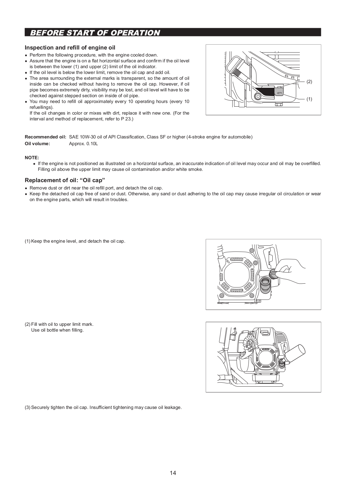
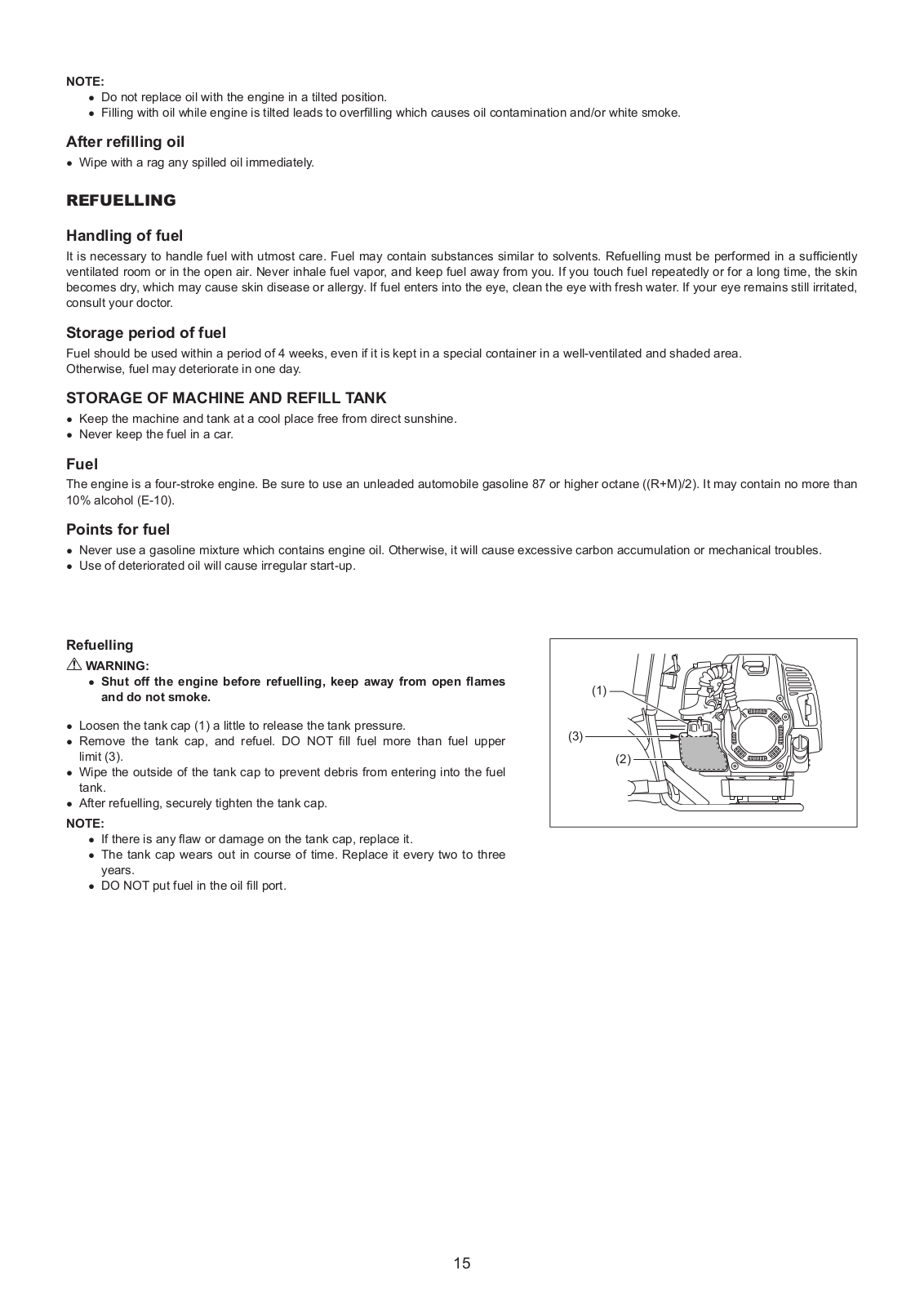
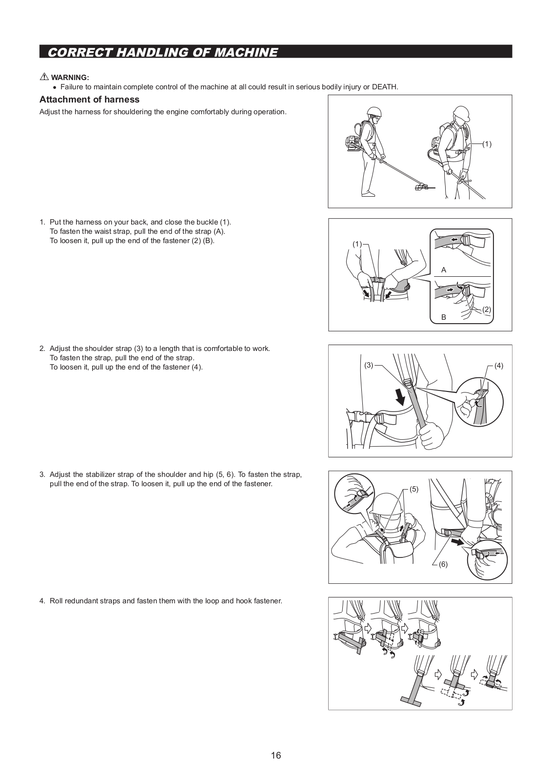
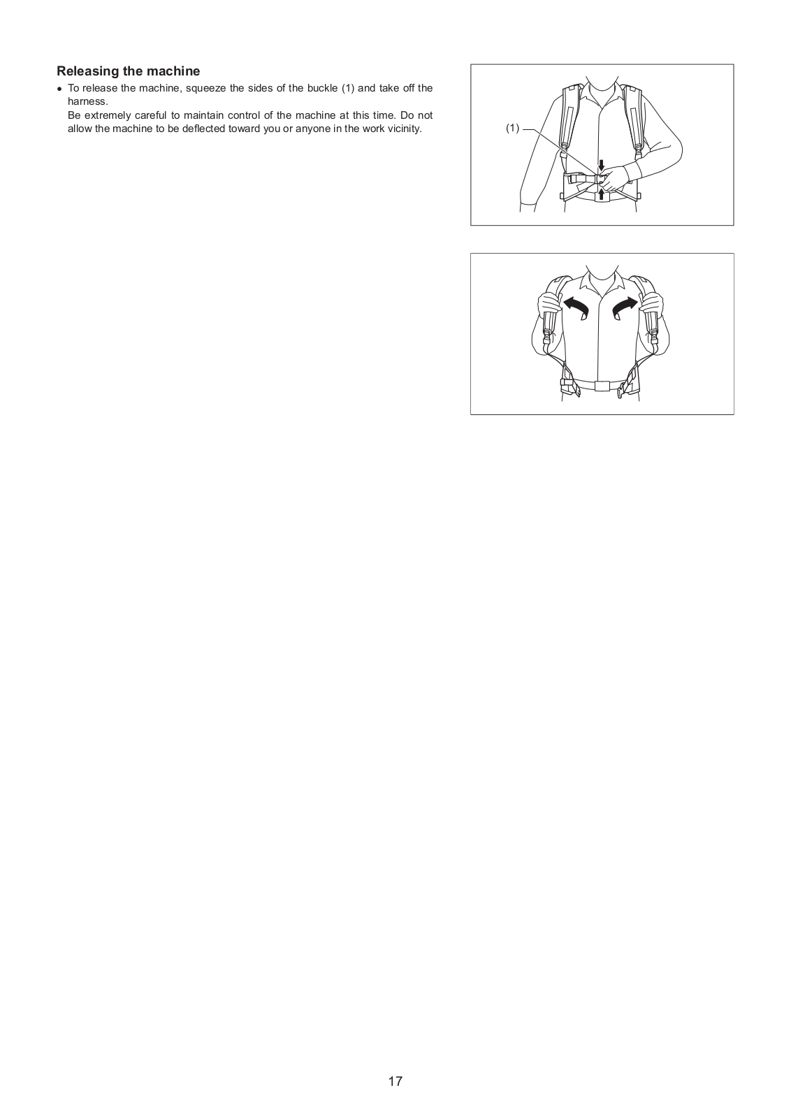
Makita EM4350RH operation manual
...
Makita operation manual
Download
Specifications and Main Features
Frequently Asked Questions
User Manual
Download
Loading...
+
40
hidden pages
Unhide
You need points to download manuals.
1 point = 1 manual.
You can buy points or you can get point for every manual you upload.
Buy points
Upload your manuals
 Loading...