


BHX2500CA
Makita BHX2500CA Manual
Important:
Read this instruction manual carefully before putting the Blower into operation and
strictly observe the safety regulations! Preserve instruction manual carefully!
Importante:
Lisez attentivement ce manuel utilisateur avant de mettre en route le souffleur et
respectez scrupuleusement les consignes de sécurité.
Conservez soigneusement ce manuel.
Importante:
Lea bien este manual antes de poner el soplador en funcionamiento, y observe
estrictamente las medidas de seguridad. Conserve este manual de instrucciones.
INSTRUCTION MANUAL
MANUEL UTILISATEUR
MANUAL DE INSTRUCCIONES
BHX2500CA
PETROL BLOWER
SOUFFLEUR À ESSENCE
SOPLADOR DE GASOLINA
English / French /
Spanish
Makita CA Statement
Makita non CA Statement
BHX2500CA
BHX2500
(P2~P19)
(P20~P37)
(P38~P55)
2
Thank you very much for selecting the MAKITA blower. We are pleased
to be able to offer you the MAKITA blower which is the result of a long
development programme and many years of knowledge and
experience.
The blower models BHX2500/BHX2500CA combines the advantages
of state-of-the-art technology with ergonomic design. They are of light
weight handy, compact and represent professional equipment
for a great variety of applications.
Please read, understand and follow this booklet which refers in detail
to the various points that will demonstrate its outstanding
performance. This will assist you to safety obtain the best possible
results from your MAKITA Blower.
Table of Contents
Page
Symbols .......................................................................................... 2
Safety instructions .......................................................................3-5
Specification ................................................................................... 6
Designation of parts ........................................................................ 7
Assembly instructions .................................................................... 8
Before start of operation ......................................................... 9-10
Operation ................................................................................ 11-12
Adjustment of idling ......................................................................12
Operation method ......................................................................... 13
Inspection and maintenance ................................................... 14-16
Storage.......................................................................................... 16
Troubleshooting ............................................................................ 18
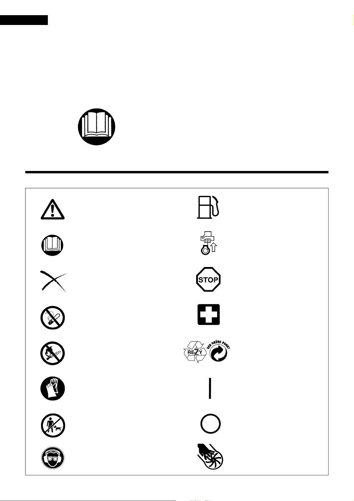
SYMBOLS
It is very important to understand the following symbols when reading this instructions manual.
English
WARNING/DANGER
Read, Understand and Follow
Instruction Manual
Forbidden
No Smoking
No Open Flame
Protective Gloves must be Worn
Keep the Area of Operation
Clear of All Persons and Pets
Wear Eye and Ear Protection
Fuel (Gasoline)
Engine-manual Start
Emergency Stop
First Aid
Recycling
ON/START
OFF/STOP
Severing of fingers or hand,
impeller blade
SAFETY INSTRUCTIONS
General Instructions
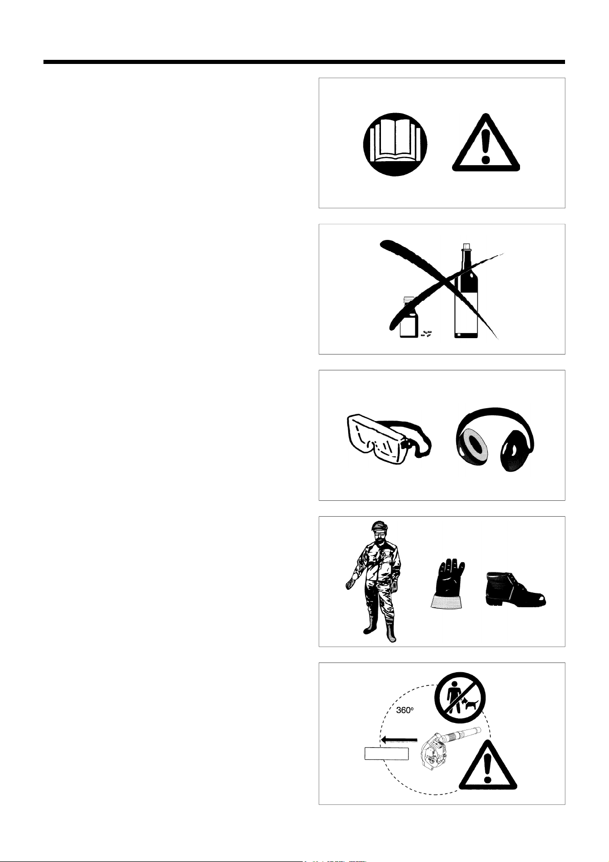
• To ensure correct and safe operation, the user must read,
understand and follow this instruction manual to assure familiarity
with the handling of the blower (1). Users insufficiently informed
will risk danger to themselve s as well a s others due t o improp er
handling.
• It is recommended only to loan the blower to people who have
proven to be experienced with blowers.
• Always hand over the instruction manual.
• First-time users should ask the dealer for basic instructions to
familiarize oneself with the hand ling of a blower.
• Children and young persons aged under 18 years must not be
allowed to operate the blower. Persons over the age of 16 years
may however use the tool for the purpose of being trained only
while under the direct supervision of a qualified trainer.
• Use blowers with the utmost care and attention.
• Operate the blower only if you are in good physical condition.
• Perform all work conscientiously and carefully. The user has to
accept responsibility for others.
• Never use the blower while under the influence of alcohol or drugs
(2).
• Do not use the unit when you are tired.
• Save these instructions for future referral.
Personal Protective Equipment
• The clothing worn should be functional and appropriate, I. e. It
should be tight-fitting but not cause a hinderance. Do not wear
jewelry, clothing or long hair which could be drawn into the air
intake.
• In order to avoid head-, eye-, hand- or foot in juries a s well as to
protect your hearing the following protecti ve equipmen t and
protective clothing must be used during operat ion of t he blower.
Pay particular attention to the following regulations
• Clothing must be sturdy and snug-fitting, but allow complete
freedom of movement. Avoid loose-fitting jackets, flared or cuffed
pants, scarfs, unconfined long hair or anything that could be drawn
into the air intake. Wear overalls or long pants to protect your legs.
Do not wear shorts. (4)
• Blower noise may damage your hearing. Wear sound barriers (ear
plugs or ear mufflers) to protect your hearing. Continual and
regular users should have their hearing checked regularly. (3)
• Use of gloves when working with the blower is recommended.
Good footing is most important. Wear sturdy shoes with nonslip
soles. (4)
• Proper eye protection is a must. Even though the discharge is
directed away from the operator, ricochets and bouncebacks can
occur during blower operation. (3)
• Never operate a blower unless wearing goggles or properly fitted
safety glasses with adequate top and side protection which comply
with ANSI Z 87. 1 (or your applicable national standard).
Starting up the blower
• Please make sure that there are no children or other people within a
working range of 15 meters (5), also pay attention to any animals in
the working vicinity. Never use the blower in urban areas.
• Before operating, always check that the blower is safe for
operation:
Check the security of the throttle lever. The throttle lever should be
checked for smooth and easy action. Check for proper functioning
of the throttle lever lock. Check for clean and dry handles and test
the function of the l-O switch. Keep handles free of oil and fuel.
(1)
(2)
(3)
(4)
(5)
15meters
3
4
Start the Blower only in accordance with the instructions.
Do not use any other methods for starting the engine (6) !
• Use the blower and the tools supplied only for appli cations
specified.
• Start the blower engine only after the entire tool has been
assembled. Operation of the tool is permitted only after all
the appropriate accessories are attached.
• The engine is to be switched off immediately if there are any engine
problems.
• When working with the blower, always wrap your fingers tightly
around the handle, keeping the control handle cradled between
your thumb and forefinger. Keep your hand in this position to have
your machine under control at all times. Make sure your control
handle (and grip for vacuum attachment) are in good condition and
free of moisture, pitch, oil or grease.
Always ensure a safe, well-balanced footing.
• Operate the blower in such a manner as to avoid inhalation of the
exhaust gases. Never run the engin e in enclo sed rooms (ri sk of
suffocation and gas poisoning). Carbon monoxide is an odorless
gas. Always ensure there is adequate ventilation.
• Switch off the engine when rest ing and when leav ing the blower
unattended. Place it in a safe location prevent danger to others,
setting fire to combustible material s, or dam age to the mac hin e.
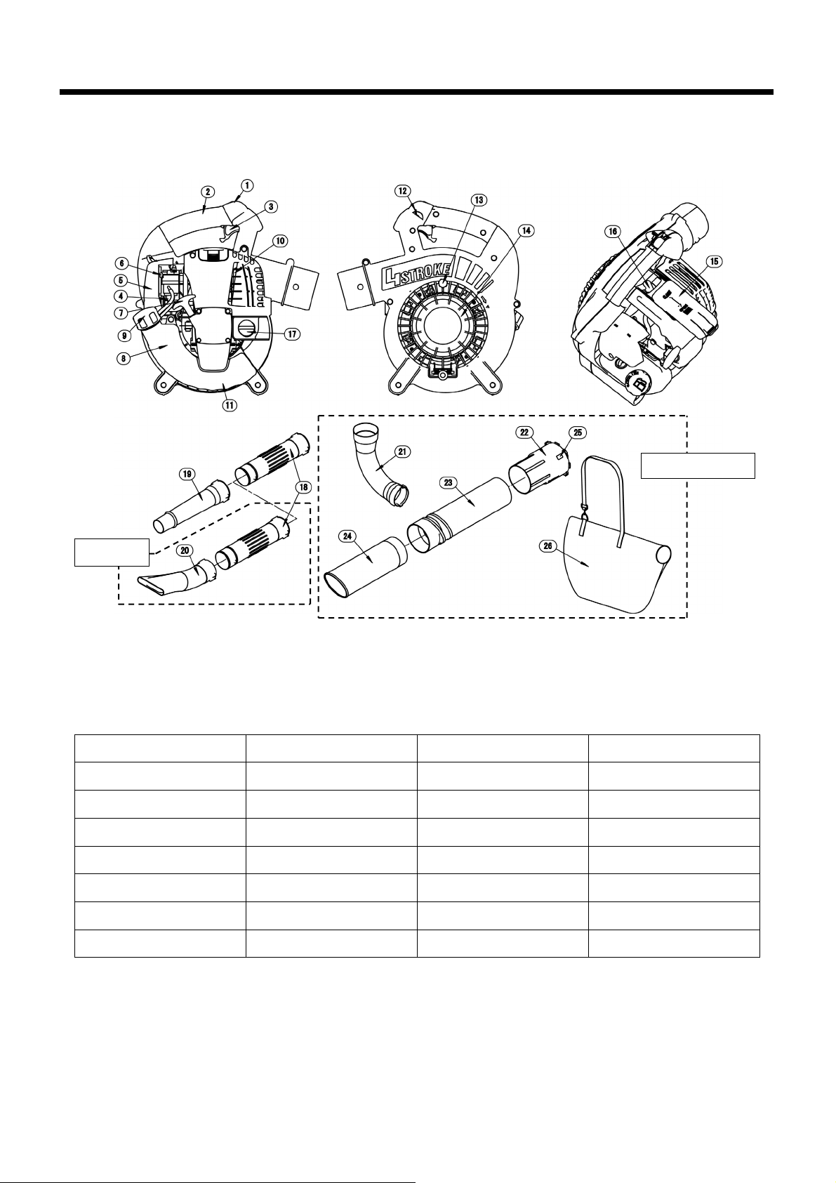
• Never lay the hot blower onto dry grass or onto any combustible
materials.
• All protective parts and guards supplied with the machine must be
used during operation.
• Never operate the engine with a faulty exhaust muffler.
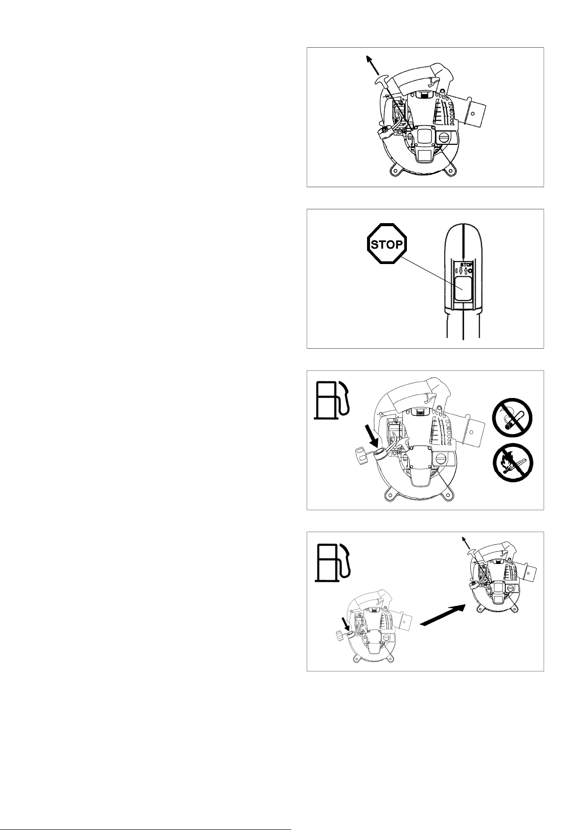
• Shut off the engine d uring tra nsport ( 7).
• Position the blower safel y during car or truc k transpor tation to a void
fuel leakage.
• When transporting the blower, ensure that the fuel tank is
completely empty.
Refuelling
• Shut off the engine during refuelling (7), keep well away from open
flame (8) and do not s moke.
• Avoid skin contact with petroleum products. Do not inhale fuel
vapor. Always wear protective gloves during refuelling. Change
and clean protective clothing at regular intervals.
• Take care not to spill either fuel or oil in order to prevent soil
contamination (environmental protection). Clean the blower
immediately after fuel has been spilt. Allow wet cloths to dry
before disposing in properly, covered container to prevent
spontaneous combustion.
• Avoid any fuel contact with your clothing. Change your clothing
immediately if fuel has been spilled on it (fire hazard).
• Inspect the fuel cap at regular intervals making sure that it stays
securely fastened.
• Carefully tighten the locking screw of the fuel tank. Change
locations to start the engine (at least 3 meters away from the place
of refuelling) (9).
• Never refuel in closed rooms. Fuel vapors accumulate at ground
level (risk of explosions)
• Only transport and store fuel in approved containers. Make sure
stored fuel is not accessible to childre n.
• Do not attempt to refuel a hot or a running engine.
●
Resting
●
Tra ns por t
●
Refuelling
●
Maintenance
●
Tool Replacement
(6)
(7)
(8)
(9)
3 meters
4
5
Method of operation
• Use the blower only in good light and visibility. During cold seasons
beware of slippery or wet areas, ice and snow (risk of slipping).
Always ensure a safe footing.
• Never work on unstable surfaces or sleep terrain.
• To reduce the risk of personal injury, do not direct air blast towards
bystanders, since the high pressure of the air flow could injure
eyes and could blow small o bjects at great speed.
• Never insert any foreign object into the air intake of the machine or into
the nozzle of the blower. It will damage the fan wheel and may cause
serious injury to the operator or bystanders as a result of the object or
broken parts being thrown out at high speed.
• Pay attention to the direction of the wind, i.e., do not work against
the wind.
• To reduce the risk of stumbling and loss of control, do not walk
backward while operating the machine.
• Always shut off the engine before cleaning or servicing the unit or
replacing parts.
Maintenance instructions
• Be kind to the environment. Operate the blower with as little noise
and pollution as possible. In particular check the correct adjustment
of the carburetor.
• Clean the blower at regu lar int ervals an d check that all screws and
nuts are securely tightened.
• Never service or store the blower in the vicinity of open flames,
sparks, etc. (11).
• Always store the blower in a well-ventilated locked room and with
an emptied fuel tank.
Observe and follow all relevant accident prevention
instructions issued by the trade associations and by
insurance companies. Do not perform any modifications to
the blower as this will risk your safety.
The performance of maintenance or repair work by the user is limited
to those activities as described in this instruction manual. All other
work is to be done by Authorized Service Agents.
Use only genuine spare parts and accessories supplied by MAKITA.
Use of non-approved accessories and tools means increased risk of
accidents and injuries. MAKITA will not accept any liability for accidents
or damage caused by the use of an y non-approv ed attac hment or
accessories.
First Aid
In case of accident make sure that a well-stocked first-aid kit is
available in the vicinity of the operations. Immediately replace any item
taken from the first aid kit.
When asking for help, please give the following information:
• Place of accident
• What happened
• Number of injured persons
• Extent of injuries
•Your name
Packaging
The MAKITA blower is delivered in a protective cardboard box to
prevent shipping damage. Cardboard is a basic raw material and is
therefore consequently reusable or suitable for recycling (waste
paper recycling).
(10)
(11)
(12)
5

SPECIFICATION
Notes:
1. Use the oil and spark plug specified by MAKITA.
2. This specification is subject to change without prior notice.
Model BHX2500/BHX2500CA
Mass (without blower pipe) (kg) 4.5 (9.9 lbs)
Dimension (without blower pipe L x W x H) (mm) 350×231×368 (13.8×9.1×14.5 in)
Max. engine speed ( /min) 7,800
Idling speed ( /min) 3,500
Engine displacement (mL)
24.5(1.49 cu,in)
Fuel
Automobile gasoline
Fuel tank capacity (L)
0.52 (17.6 fl.oz)
Engine oil
SAE 10W-30 oil of API Classification, Class SF or higher
(4-stroke engine for automobile)
Engine oil volume (L)
0.08 (2.7 fl.oz)
Carburetor (Diaphragm-carburetor)
WALBRO WYL
Ignition system
Solid state ignition
Spark plug
NGK CMR6A
Electrode gap (mm)
0.7 - 0.8 (0.028-0.031 in)
6
Bystander noise per ANSI B 175.2-2000 dB(A) 67
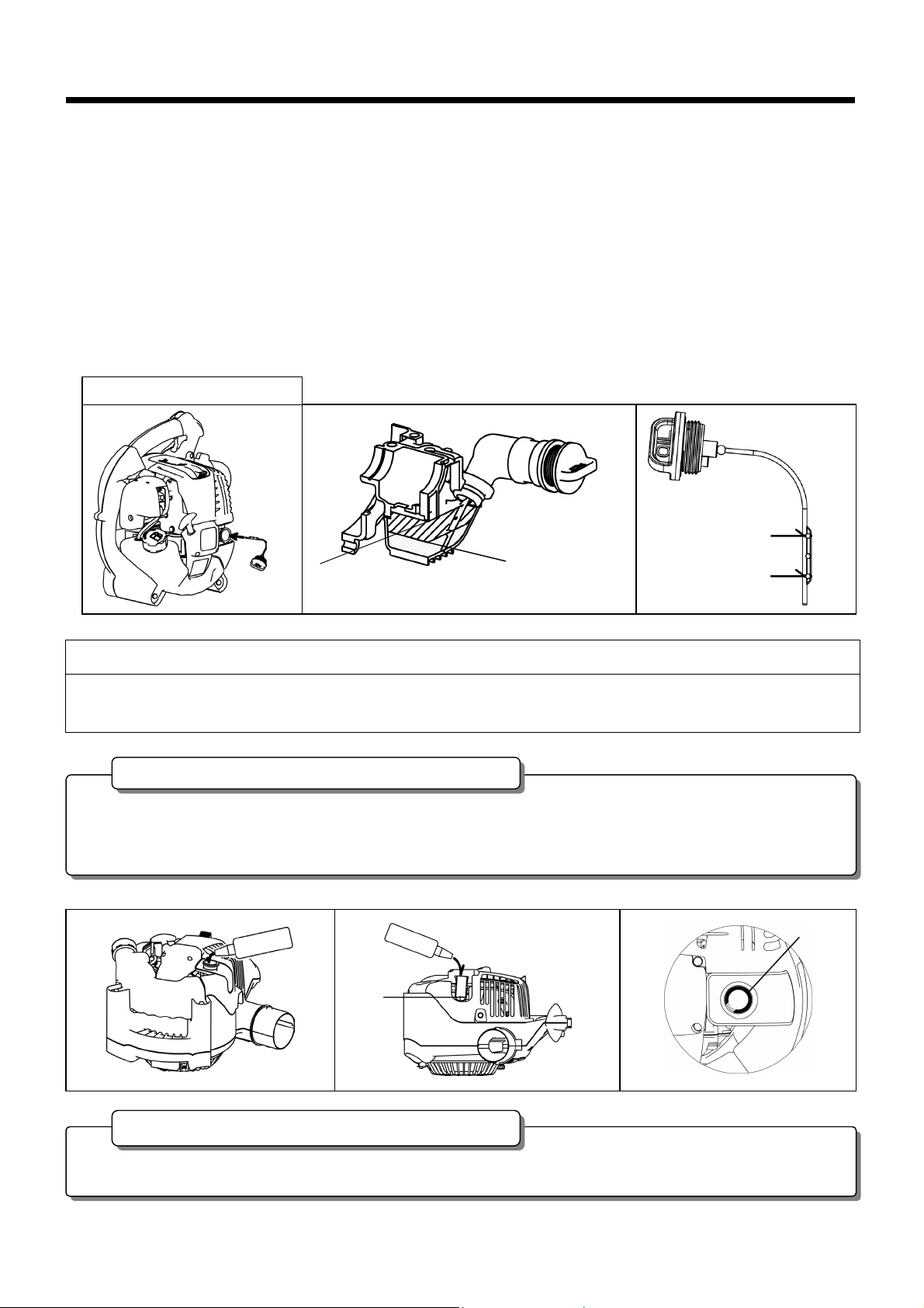
DESIGNATION OF PARTS
DESIGNATION OF PARTS
DESIGNATION OF PARTS
DESIGNATION OF PARTS DESIGNATION OF PARTS
1. Stop switch 8. Fuel Tank 15. Plug Cover 22. Vacuum Pipe A
2. Main Handle 9. Fuel Tank Cap 16. Spark Plug 23. Vacuum Pipe B
3. Trigger Lever 10. Muffler 17. Oil Cap 24. Vacuum Pipe C
4. Primer Pump 11. Assist Handle 18. Blower Tube 25. Arrow Mark
5. Air Cleaner Cover 12. Cruise Control Lever 19. Blower Nozzle A 26. Dust Bag
6. Choke Lever 13. Screw 20. Blower Nozzle B
7. Starter Handle 14. Protector 21. Elbow
Vacuum set (Optional)
Optional
7
ASSEMBLY INSTRUCTIONS
CAUTION : Before performing any work on the blower,
always switch off the motor and pull the spark
plug connectors off the spark plug.
Always wear protective gloves!
CAUTION : Start the blower only after having assembled it
completely.
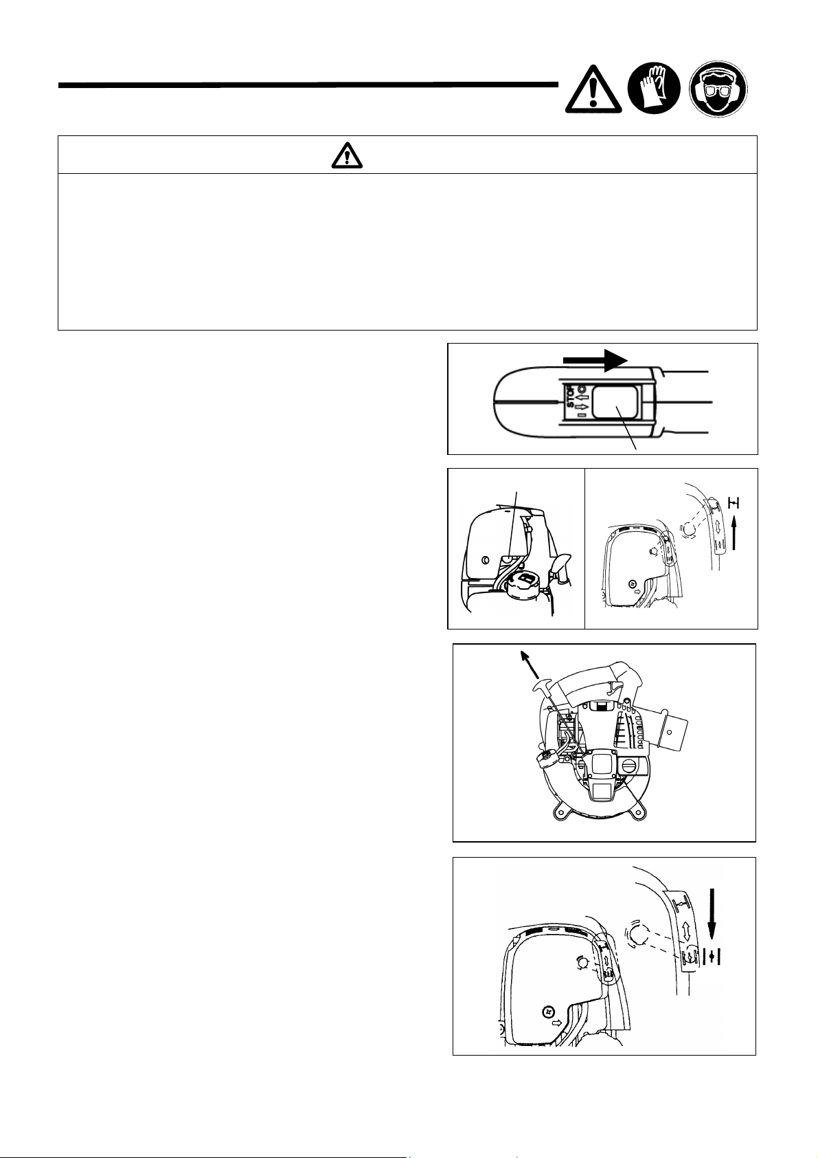
1. ASSEMBLY OF BLOWER PIPES
1) Align grooves in the blower pipe with pegs on the blower housing
and slide the pipe onto housing.
2) Turn the bl ower pipe clockwise to lock it into place.
2. ASSEMBLY OF VACUUM ATTACHMENT
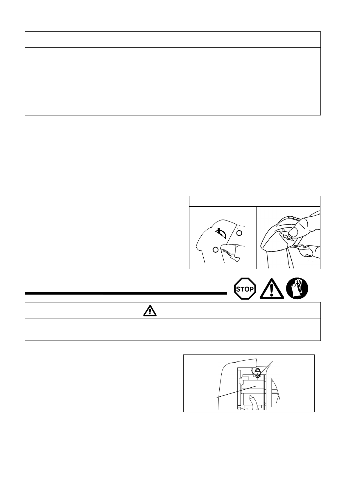
1) Installing Vacuum pipe (nozzle)
(1) Loosen the screw ① and open the protector ② .
WARNIN G!
When using this machine as a blower, be sure to
confirm that the screw ① is not loosened at each time
of startup. If the screw is loosened, retighten it.
It is dangerous to operate the machine with the screw ① loosened.
The operator’s finger or clothing may be caught in the impeller, which
will result in a serious accident.
(2) Align the indicated on the vacuum pipe with the “ ● “
indicated on the blower. Then insert the vacuum pipe into the
blower.
(3) Turn the vacuum pipe until the is aligned with the “
▼
“
indicated on the blower to lock the vacuum pipe.
WARNIN G!
Always hold the mounting end of the vacuum pipe when attaching/
detaching the vacuum pipe.
2) Inst alling Elbow and Dust Bag
(1) Open the fastener of the dust bag.
(2) Insert the elbow into the dust bag and take it out through the
bag’s entry.
(3) Install the elbow on the blower.
WARNIN G!
Do not attempt to pick up large wood chips, metals,
glass, stones, liquids, lighted cigarettes, fire works or
the like.
Always mount the protector/vacuum pipe in the right way before
operation. Operation without the protector/vacuum pipe is dangerous,
the impeller may catch the operator’s fingers or clothes and it can
result in serious injury.
①
②
Screw
Protector
8
BEFORE START OF OPERATION
1. Inspection and Refill of Engine Oil
(1) Perform the following procedure, with the engine cooled down.
• Inspection: Please inspect whether it makes the machine horizontal, removes the oil cap, there is a oil to inside the range of the
upper limit lower limit mark of gauge. When it is insufficient, (especially, when it has not reached to the lower limit
level), please refill new oil.
• Refill: Verticality (under the suction port cover) please do the machine, remove the oil cap. When oil is supplied from the oil
pipe port and oil level comes to the shelf inside the oil pipe, please stop oil supply.
(2) For reference, the oil refill time is about 10 h (refill frequency: 10 times).
(3) If the oil changes in color or mixes with dirt, replace it with new one. (For the interval and method of replacement, refer to P. 14)
Recommended oil: SAE 10W-30 oil of API Classification, Class SF or higher (4-stroke engine for automobile)
Oil volume: Approx. 0.08 L (2.7 fl.oz)
NOTE
• If the engine is not kept upright, oil may go into around the engine, and may be refilled excessively.
• If the oil is filled above the limit, the oil may be contaminated or may catch fire with white smoke.
• Remove dust or dirt near the oil refill port, and detach the oil gauge.
• Keep the detached oil gauge free of sand or dust. Otherwise, any sand or dust adhering to the oil gauge may cause irregular oil
circulation or wear on the engine parts, which will result in troubles.
• As an example to keep the oil gauge clean, it is recommended to insert the oil gauge on its knob side into the engine cover.
Point 1 in Replacement of Oil “Oil Gauge”
• It becomes cause of the oil soiling. Be sure to wipe out spilt oil before start of operation.
Point 2 in Replacement of Oil: “If oil spills out”
Upper limi
t
Lower limi
t
Lower limit
Shel
f
Shelf
Inspection method of engine oil
Upper limit
9

2. Fuel supply
STORAGE PERIOD OF FUEL
Fuel should be used up within a period of 4 weeks, even if it is kept in a special container in a well-ventilated shade.
If a special container is not used or if the container is not covered, fuel may deteriorate in one day.
FUEL
The engine is a four-stroke engine. Be sure to use an automobile gasoline (regular gasoline or premium gasoline).
When refueling the fuel, be sure to stop the engine and confirm that the engine cools down.
REFUELING METHOD
• Loosen the tank cap a little so that there will be no difference in atmospheric pressure.
• Detach the tank cap, and refuel, discharging air by tilting the fuel tank so that the refuel port will be oriented upward. (Never refill fuel full to
the oil refill port.)
• After refueling, securely tighten the tank cap.
• If there is any flaw or damage on the tank cap, replace it.
• The tank cap is consumable, and therefore should be renewed every two to three years.
WARNING
• When supplying the fuel, be sure to observe the following instructions to prevent ignition or fire:
- Fuel supply must be made in a place free of fire. Never bring the fire (smoking, etc.) near to the place of fuel supply.
- Stop the engine and allow the engine to cool down before fuel supply.
- Open the fuel tank cap full of fuel slowly. The fuel may sprout out under internal pressure.
- Take care not to spill the fuel. Any spilled fuel must be wiped clean.
- Carry out fuel supply in a well-ventilated place.
• Handle the fuel with care.
- Fuel sticking to the skin or entering an eye may cause allergies or irritation. When any physical abnormality is detected, consult the
medical specialist immediately.
• Keep the machine and tank at a cool place free from direct sunshine.
• Never keep the fuel in the cabin or trunk.
Storage of machine and refill tank
• Never use a gasoline mixture which contains engine oil. Otherwise, it will cause excessive carbon accumulation or mechanical
troubles.
• Use of deteriorated oil will cause irregular startup.
Points for Fuel
10
OPERATION
1. Starting
1) When the engine is cold, or when the fuel it refueled
(1) Set this machine on a flat space.
(2) Set the stop switch to “ I “ position.
(3) Continue to push the primer pump until fuel enters into the
primer pump.
• In general, fuel enters into the carburetor by 7 to 10 pushes.
• If the primer pump is pushed excessively, an excess of
gasoline returns to the fuel tank.
(4) Lifting the choke lever of the air cleaner right side, close the
choke lever.
(5) Hold the main handle with a left hand to prevent the engine
from moving, settle down to take the stable position.
(6) Pull out slowly the starter handle till a certain resistance is felt.
Return the starter handle backward once from this position,
then pull it out with force.
• Never pull the rope to the full.
• Once the start knob is pulled, never release your hand
immediately. Hold the start knob until it returns to its original
point.
(7) When the engine starts, open the choke lever.
• Open the choke lever progressively while checking the engine
operation. Be sure to open the choke lever to the full in the
end.
• In cold or when the engine is cooled down, never open the
choke lever suddenly. Otherwise, the engine may stop.
(8) Continue warm-up operation for 2 to 3 minutes.
(9) Rotation of the engine speed stabilizes and when from low
speed making at high speed rotation, if reaches the point
where it accelerates smoothly, it is completion of warming-up.
WARNING
• Never attempt engine start in a place where the fuel has been supplied. When starting the engine, keep a distance of at least 3 m.
- Otherwise, it will may cause ignition or fire.
• Exhaust gas from the engine has toxic consequences. Do not operate the engine in a poorly-ventilated place, such as in a tunnel,
building, etc.
- Operating the engine in the poorly-ventilated place may cause poisoning by exhaust gas.
• In case of detection of any abnormality in sound, odor, vibration after start, stop the engine immediately and carry out inspection.
- If the engine is operated without attending such abnormality, an accident may occur.
• Confirm that the engine stops when the stop switch is set to “O” position.
(2)
Stop Switch
Primer pump
Open
(6)
(7)
Close
(3) (4)
11
2) When the engine is warm
(1) Place the engine on a flat ground.
(2) Press the primary pump several times.
(3) Confirm that the choke lever is open.
(4) Hold the main handle with a left hand to prevent the engine from moving, settle down to take the stable position.
(5) Pull out slowly the starter handle till a certain resistance is felt. Return the starter handle backward once from this position, then pull it
out with force.
(6) When the engine is difficult to start, open the throttle valve by about 1/3.
2. Stopping
1) When the cruise control lever is OFF
Release the trigger lever to reduce the engine speed, and set the
stop switch to the “O” position.
2) When the cruise control lever is ON
Set the cruise control lever to the OFF position, reduce the engine
speed, and set the stop switch to the “O” position.
ADJUSTMENT OF IDLING
Checkup of low-speed rotation
Set the low-speed rotation to 3500 ( /min).
• If it is necessary to change the rotation speed, regulate the
adjusting screw, with Phillips screwdriver.
• Turn the adjusting screw to the right, and the engine rotation will
increase. Turn the adjusting screw to the left, and the engine
rotation will drop.
NOTE
• The engine may be damaged if the choke lever is moved further beyond the “CLOSE” position.
• If the engine stops with an explosion sound or if the engine started, but stopped before operation of the choke lever, return this lever to
the “OPEN” position and pull the starter handle several times to start the engine again.
• If the operator keeps pulling the starter handle several times with the choke lever left in the “CLOSE” position, the engine may be difficult
to start because of over-suction of the fuel.
• In case of over-suction of the fuel, remove the spark plug and pull the handle several times rapidly to discharge any excess fuel. Dry
the spark plug electrode.
• When the throttle valve does not return to a position in contact with the idling adjusting screw even if the throttle lever is set to the low
speed, correct the control cable catching state to ensure proper return of the valve.
DANGER
The carburetor is the adjustment being completed at the time of factory shipment. Please do not adjust other than idling adjusting. When
adjustment becomes necessary, please consult your dealership or an authorized service agent.
A
djusting screw
Carbureto
r
Cruise control lever
OFF ON
12
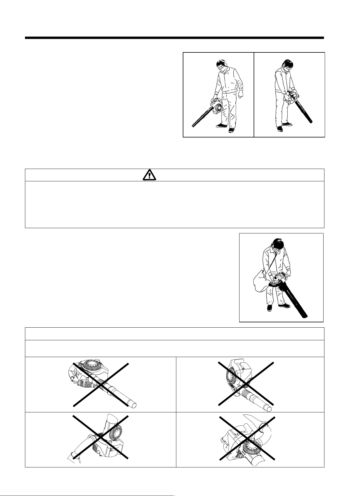
OPERATION METHOD
1. Blower operation
• Hold the machine firmly during operation.
• Direct the nozzle end toward the object to be dusted and pull the
trigger lever.
• The trigger lever can be fixed in an arbitrary position with the cruise
control lever.
• Maintain the trigger lever at a position where the engine speed
appropriate for the operation is obtained and set the cruise control
lever to the “ON” position.
• To adjust the engine speed, set the cruise control lever to the
“OFF” position once, adjust the engine speed with the trigger lever
again, then set and fix the cruise control lever to the “ON” position.
• Operation of the trigger lever with the cruise control lever in the
“ON” position may cause failure.
• The lower portion of the fuel tank acts as an assist handle, which
enables operation with both hands. In this case, be sure to hold
the assist handle with a right hand.
2. Dust Collection Operation
• Carry the dust bag belt on the shoulder and adjust the belt length to ensure easy operation.
• Confirm that the dust bag is not twisted and pull the trigger lever to start dust collection.
• When the dust bag is filled with dust, remove the dust bag from the machine and open the
fastener to empty the bag.
WARNING
• Do not allow kerosene, gasoline, or lighted cigarette to be sucked into the machine.
- Otherwise, fire may occur.
• Do not allow foreign materials, such as large wood chips, metals, glass, pebbles, etc., to be sucked into the machine.
- Otherwise, failure may occur.
• Overfilling of the dust bag with dust may cause its overflow toward the engine side. Empty the bag in a proper timing.
- Otherwise, the fire may occur.
NOTE
If this machine is operated with the protector oriented upwards or the main handle downwards, there may appear white smoke,
oil contamination or oil leakage.
13
INSPECTION AND MAINTENANCE
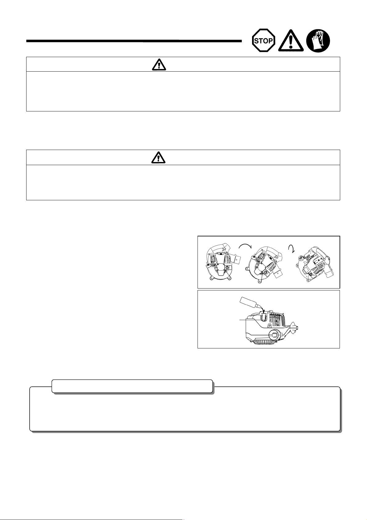
1. Replacement of engine oil
Deteriorated engine oil will shorten the life of the sliding and rotating parts to a great extent. Be sure to check the period and quantity of
replacement.
Interval of replacement: Initially, every 20 operating hours, and subsequently every 50 operating hours
Recommended oil: SAE10W-30 oil of API Classification SF Class or higher (4-stroke engine oil for automobile)
In replacement, perform the following procedure.
(1) Confirm that the tank cap is tightened securely.
(2) Detach the oil cap.
- Keep the oil gauge free from dust or dirt.
(3) The machine it can tilt to the blower port side, drain oil.
- Drain oil in a container.
(4) Please make the machine vertical (under the protector), refill oil
to the shelf inside the oil pipe.
(5) After refill, securely tighten the oil gauge. Insufficient tightening of
the oil gauge will lead to oil leakage.
DANGER
• Before inspection and maintenance, stop the engine and allow it to cool. Remove also the spark plug and plug cap.
- If inspection or maintenance is attempted immediately after engine stop or with the plug cap left attached, the operator may suffer burn
or an accident due to careless startup.
• After inspection and maintenance, be sure to confirm that all parts are assembled. Then, proceed to operation.
DANGER
• In general, the engine main unit and engine oil still remain hot just after the engine is stopped. In replacement of oil, confirm that the
engine main unit and engine oil are sufficiently cooled down. Otherwise, there may remain a risk of scald. In addition just after of the
engine stopping because oil does not finish to return in the oil case, becomes cause of the oil inserting too much.
• If the oil filled above the limit, it may be contaminated or may catch fire with white smoke.
• Never discard replaced engine oil in garbage, earth or sewage ditch. Disposal of oil is regulated by law. In disposal, always follow the
relevant laws and regulations. For any points remaining unknown, contact Authorized Service Agent.
• Oil will deteriorate even when it is kept unused. Perform inspection and replacement at regular intervals (replace with new oil every 6
months).
Points in replacement of engine oil
(4)
Shelf
(3)
14
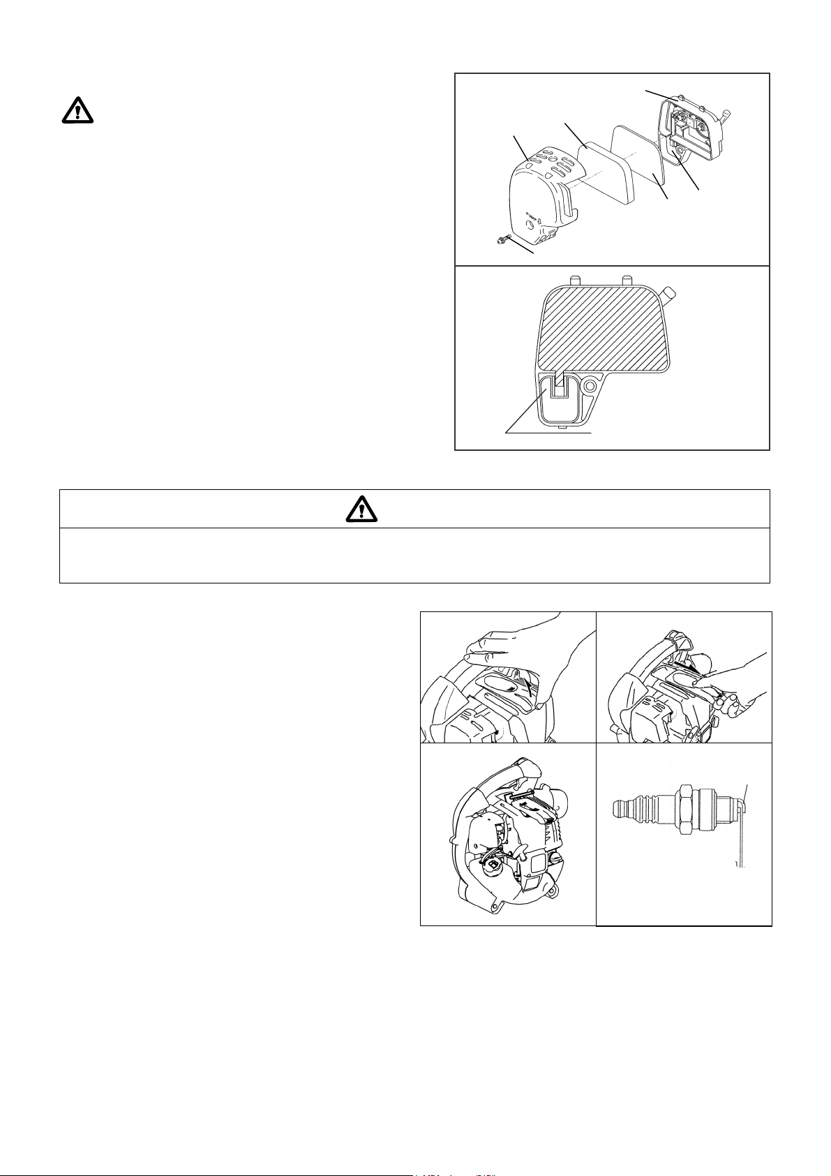
2. Cleaning of air cleaner
WARNING : INFLAMMABLES STRICTLY PROHIBITED
Interval of Cleaning and Inspection: Daily (every 10 operating hours)
(1) Remove the air cleaner cover-fixing bolts.
(2) Pull the cover lower side and detach the air cleaner cover.
(3) Turn the choke lever to the full close side, and keep the carburetor off
from dust or dirt.
(4) If oil adheres to the element (sponge), squeeze it firmly.
(5) For heavy contamination:
1) Remove the element (sponge), immerse it in warm water or in
water-diluted neutral detergent, and dry it completely.
2) Clean the element (felt) with gasoline, and dry it completely.
(6) Before attaching the element, be sure to dry it completely. Insufficient
drying of the element may lead to difficult startup.
(7) Wipe out with waste cloth, oil adhering around the air cleaner cover
and plate breather.
(8) Immediately after cleaning is finished, attach the air cleaner cover and
tighten it with fixing bolts. (In remounting, first place the upper claw,
and then the lower claw.)
3. Checking the spark plug
(1) Opening/closing the plug cover
When opening the cover, apply fingers to the main handle and
plug cover projection as shown in the figure right. Push up the
projection and slide the cover in the “OPEN” direction.
When closing the cover, slide the cover in the “CLOSE” direction
till the click under the plug cover projection rides over the engine
cover. Finally, push in the projection.
(2) Removing the spark plug
Use an attached box wrench to remove or install the spark plug.
(3) Checking the spark plug
The clearance between two electrodes of spark plug (see the
figure left) is 0.7 to 0.8 mm. Adjust to the correct clearance when
it is too wide or too narrow.
Clean thoroughly or replace the spark plug if it has accumulated
carbon or contaminated.
(4) Replacing the spark plug
For replacement, use NGK-CMR6A.
DANGER
• Clean the element several times a day, if excessive dust adheres to it.
• If operation continues with the element remaining not cleared of oil, oil in the air cleaner may fall outside, resulting in oil contamination.
Pick this part and remove the
element (felt).
Element (felt)
Element
(sponge)
A
ir cleaner
cover
Fixing bolt
Breather Part
Plate
(3)
(1)
(2)
Lateral electrode (-)
Electrode clearance
0.7 - 0.8 mm
(0.028-0.031 in)
15
4. Cleaning the fuel filter
• Clogged fuel filter may cause difficulty of startup or failure of engine
speed increase.
• Check the fuel filter regularly as follows:
(1) Remove the fuel tank cap, drain the fuel to empty the tank. Check the
tank inside for any foreign materials. If any, wipe clean such
materials.
(2) Pull out the fuel filter with wire through the oil filling port.
(3) If the fuel filter surface is contaminated, clean it with gasoline. Foul
gasoline must be disposed of according to the method specified by
each local authority. Excessively foul filter must be replaced.
(4) Reset the fuel filter in the fuel tank and tighten firmly the fuel tank cap.
For replacement, contact your dealership or an authorized service
agent.
5. Inspection of bolts, nuts and screws
• Retighten loose bolts, nuts, etc.
• Check for fuel and oil leakage.
• Replace damaged parts with new ones for safety operation.
6. Cleaning of parts
• Keep the engine always clean.
• Keep the cylinder fins free of dust or dirt. Dust or dirt adhering to the fins will cause seizure.
7. Replacement of gaskets and packings
In reassembling after the engine is dismounted, be sure to replace the gaskets and packings with new ones.
Any maintenance of adjustment work that is not included and described in this manual is only to be performed by Authorized Service Agents.
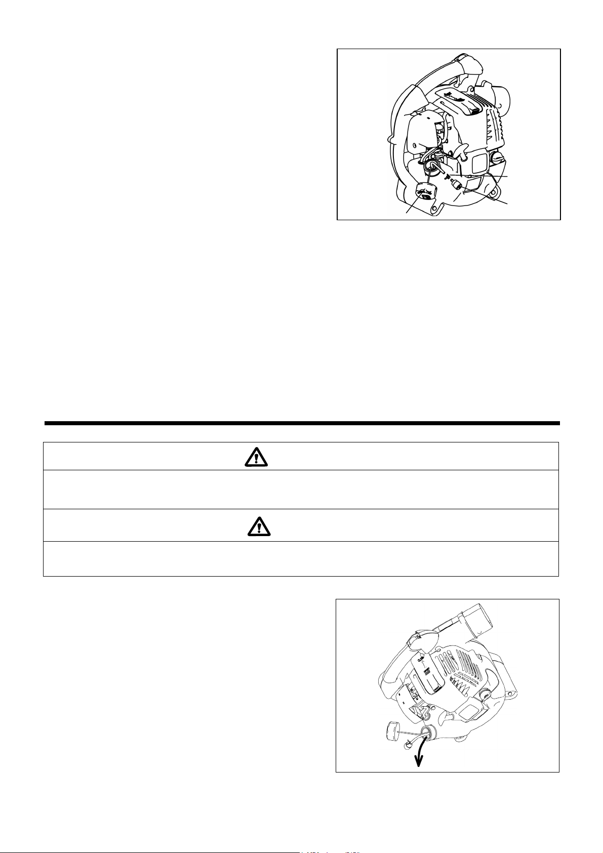
STORAGE
Drain up fuel from the fuel tank and carburetor according to the following
procedure:
(1) Remove the fuel tank cap, and drain fuel completely.
If there is any foreign matter remaining in the fuel tank, remove it
completely.
(2) Pull out the fuel filter from the refill port using a wire.
(3) Push the primer pump until fuel is drained from there, and drain fuel
coming into the fuel tank.
(4) Reset the filter to the fuel tank, and securely tighten the fuel tank cap.
(5) Then, continue to operate the engine until it stops.
(6) Remove the spark plug, and drip several drops of engine oil through
the spark plug hole.
(7) Gently pull the starter handle so that engine oil will spread over the
engine, and attach the spark plug.
(8) During storage, in order for the machine to become uprighting, please
keep.
(9) Keep the drained fuel in a special container in a well-ventilated shade.
WARNING
• When draining the fuel, be sure to stop the engine and confirm that the engine cools down.
- Just after stopping the engine, it may still hot with possibility of burns, inflammability and fire.
DANGER
• When the machine is kept out of operation for a long time, drain up all fuel from the fuel tank and carburetor, and keep it at a dry and
clean place.
Fuel tank cap
Fuel filter
Hose clamp
16

Fault location
Fault System Observation Cause
Engine not starting or with
difficulty
Ignition system Ignition spark O.K. Fault in fuel supply or compression system, mechanical
defect
No ignition spark STOP-switch operated, wiring fault or short circuit, spark
plug or connector defective, ignition module faulty
Fuel supply Fuel tank filled Incorrect choke position, carburetor defective, fuel supply
line bent or blocked, fuel dirty.
Compression No compression when
pulled over
Cylinder bottom gasket defective, crankshaft seals
damaged, cylinder or piston rings defective or improper
sealing of spark plug
Mechanical fault Starter not engaging Broken starter spring, broken parts inside of the engine
Warm start problems Tank filled ignition spark
existing
Carburetor contaminated, have it cleaned
Engine starts but dies Fuel supply Tank filled Incorrect idling adjustment, carburetor contaminated
Fuel tank vent defective, fuel supply line interrupted,
cable or STOP-switch faulty
Insufficient performance Several systems
may simultaneously
be affected
Engine idling poor Air filter contaminated, carburetor contaminated, muffler
clogged, exhaust duct in the cylinder clogged
Operating time
Item
Before
operation
After
lubrication
Daily
(10h)
30h 50h 200h
Shutdown
/rest
Corres-po
nding P
Inspect/clean ○ 9
Engine oil
Replace ○
*1
14
Tightening parts
(bolt, nut)
Inspect ○ 16
Clean/inspect ○ ―
Fuel tank
Drain fuel ○
*3
16
Throttle lever Check function ○
Stop switch Check function ○ 12
Low-speed rotation Inspect/adjust ○ 12
Air cleaner Clean ○ 15
Ignition plug Inspect ○ 15
Cooling air duct Clean/inspect ○ 16
Inspect ○ 16
Fuel pipe
Replace
◎
*2
―
Fuel filter Clean/replace ○
16
Clearance between air intake
valve and air discharge valve
Adjust
◎
*2
―
Oil tube Inspect
◎
*2
Engine overhaul
◎
*2
―
Carburetor Drain fuel ○
*3
16
*1 Perform initial replacement after 20h operation.
*2 For the 200 operating hour inspection, request Authorized Service Agent or a machine shop.
*3 After emptying the fuel tank, continue to run the engine and drain fuel in the carburetor.
17

TROUBLESHOOTING
Before making a request for repairs, check a trouble for yourself. If any abnormality is found, control your machine according to the description
of this manual. Never tamper or dismount any part contrary to the description. For repairs, contact Authorized Service Agent or local dealership.
State of abnormality Probable cause (malfunction) Remedy
Failure to operate primer pump Push 7 to 10 times.
Low pulling speed of starter rope Pull strongly.
Lack of fuel Feed fuel.
Clogged fuel filter Clean
Broken fuel tube Straighten fuel tube
Deteriorated fuel
Deteriorated fuel makes starting more difficult.
Replace with new one. (Recommended
replacement: 1 month)
Excessive suction of fuel
Set throttle lever from medium speed to high
speed, and pull starter handle until engine
starts.
If engine will not start still, remove spark plug,
make electrode dry, and reassemble them as
they originally are. Then, start as specified.
Detached plug cap Attach securely
Contaminated spark plug Clean
Abnormal clearance of spark plug Adjust clearance
Other abnormality of spark plug Replace
Abnormal carburetor Make request for inspection and maintenance.
Starter rope cannot be pulled Make request for inspection and maintenance
Engine does not start
Abnormal drive system Make request for inspection and maintenance
Insufficient warm-up Perform warm-up operation
Choke lever is set to “CLOSE” although engine
is warmed up
Set to “OPEN”
Clogged fuel filter Clean
Contaminated or clogged air cleaner Clean
Abnormal carburetor Make request for inspection and maintenance
Abnormal drive system Make request for inspection and maintenance
Detached throttle wire Attach securely
Engine stops soon
Engine speed does not increase
Abnormal drive system Make request for inspection and maintenance
Detached connector Attach securely
Abnormal electric system Make request for inspection and maintenance.
Engine does not stop.
When the engine does not start after warm-up operation:
If there is no abnormality found for the check items, open the throttle by about 1/3 and start the engine.
Run engine at idling, and set choke
lever to CLOSE.
18

19
MAKITA LIMITED ONE YEAR WARRANTY
Warranty Policy
Every Makita tool is thoroughly inspected and tested
before leaving the factory. It is warranted to be free of
defects from workmanship and materials for the period of
ONE YEAR from the date of original purchase. Should
any trouble develop during this one year period, return
the COMPLETE tool, freight prepaid, to one of Makita’s
Factory or Authorized Service Centers. If inspection
shows the trouble is caused by defective workmanship or
material, Makita will repair (or at our option, replace)
without charge.
This Warranty does not apply where:
repairs have been made or attempted by others:
repairs are required because of normal wear and
tear:
the tool has been abused, misused or improperly
maintained:
alterations have been made to the tool.
IN NO EVENT SHALL MAKITA BE LIABLE FOR ANY
INDIRECT, INCIDENTAL OR CONSEQUENTIAL DAM-
AGES FROM THE SALE OR USE OF THE PRODUCT.
THIS DISCLAIMER APPLIES BOTH DURING AND
AFTER THE TERM OF THIS WARRANTY.
MAKITA DISCLAIMS LIABILITY FOR ANY IMPLIED
WARRANTIES, INCLUDING IMPLIED WARRANTIES
OF “MERCHANTABILITY” AND “FITNESS FOR A SPE
CIFIC PURPOSE,” AFTER THE ONE YEAR TERM OF
THIS WARRANTY.
This Warranty gives you specific legal rights, and you
may also have other rights which vary from state to state.
Some states do not allow the exclusion or limitation of
incidental or consequential damages, so the above limi-
tation or exclusion may not apply to you. Some states do
not allow limitation on how long an implied warranty lasts,
so the above limitation may not apply to you.
Lire et suivre le manuel
de fonctionnement
Vous venez d’acheter un souffleur MAKITA, fruit d’importants
programmes de développement et de nombreuses années d'études
et d’expérience-et nous vous en remercions.
Les modèles BHX2500/BHX2500CA légers, pratiques et compacts,
allient les avantages d’une technologie de pointe à une conception
ergonomique, et sont des outils de professionnels pour de
Lisez soigneusement le manuel, qui traite en détail des différents
points des performances de la machine et vous aidera à en tirer le
meilleur parti possible.
Table des Matières
Page
Symboles ....................................................................................... 20
Consignes de sécurité............................................................. 21-23
Caractéristiques ............................................................................24
Liste des pièces ............................................................................ 25
Instructions de montage ................................................................ 26
Avant mise en marche..............................................................27-28
Fonctionnement ....................................................................... 29-30
Réglage du ralenti .......................................................................... 30
Mode opératoire ............................................................................31
Inspection et maintenance ....................................................... 32-34
Remisage ....................................................................................... 34
Dépannage .................................................................................... 36
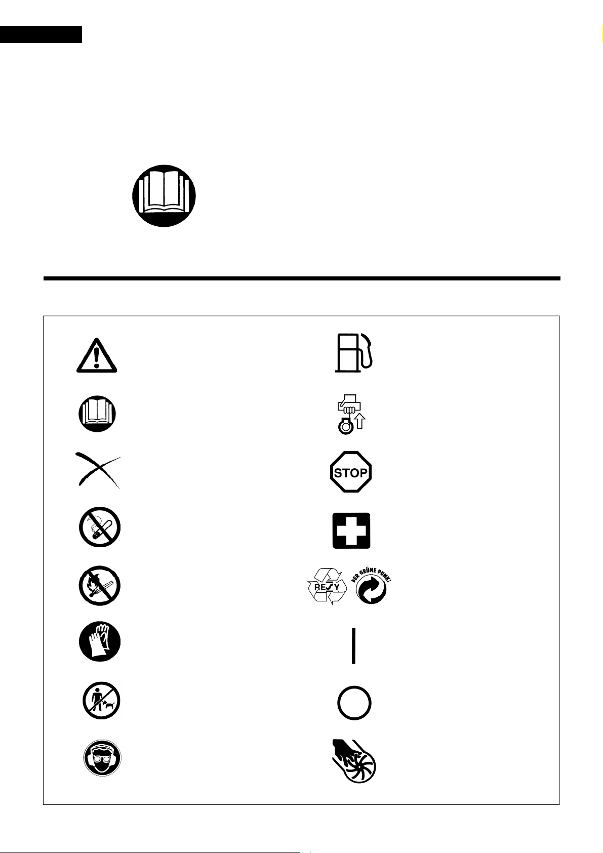
SYMBOLES
Lors de la lecture de ce manuel, prêtez une attention particuliêre aux symboles ci-après :
Attention! Danger!
Interdit
Interdiction de fumer
Interdiction d’utilisat ion de prod ui ts
inflammables
Port de gants de protection obligatoire
Zone de fonctionnement interdite aux
humains et aux animaux
Port de lunettes de protection et
cache-oreilles obligatoire
Essence et huile
Moteur - Mise en marche manuelle
Arrêt d’urgence
Premiers secours
Recyclage
Marche
Arrêt
Frençais
20
Mutilation du doigt ou du bras,
Roue mobile
norebreuses applications.
 Loading...