


 Loading...
SERVICE MANUAL
Main Section
ISpecifications
IPreparation for Servicing
IAdjustment Procedures
ISchematic Diagrams
ICBA’s
IExploded Views
IParts List
When servicing the deck mechanism, refer to MK14 Deck Mechanism Section.
Deck Mechanism Part No.:
N2466FT
20″ ANALOG/DIGITAL
PURE FLAT COLOR TV/DVD/VCR
CT202MW8

IMPORTANT SAFETY NOTICE
Proper service and repair is important to the safe, reliable operation of all Funai Equipment. The service procedures recommended by Funai and described in this service manual are effective methods of performing service operations. Some of these service special tools should be used when and as recommended.
It is important to note that this service manual contains various CAUTIONS and NOTICES which should be carefully read in order to minimize the risk of personal injury to service personnel. The possibility exists that improper service methods may damage the equipment. It also is important to understand that these CAUTIONS and NOTICES ARE NOT EXHAUSTIVE. Funai could not possibly know, evaluate and advice the service trade of all conceivable ways in which service might be done or of the possible hazardous consequences of each way. Consequently, Funai has not undertaken any such broad evaluation. Accordingly, a servicer who uses a service procedure or tool which is not recommended by Funai must first use all precautions thoroughly so that neither his safety nor the safe operation of the equipment will be jeopardized by the service method selected.
Manufactured under license from Dolby Laboratories.
“Dolby” and the double-D symbol are trademarks of Dolby Laboratories.

MAIN SECTION
20″ ANALOG/DIGITAL
PURE FLAT COLOR TV/DVD/VCR
CT202MW8
Main Section
ISpecifications
IPreparation for Servicing
IAdjustment Procedures
ISchematic Diagrams
ICBA’s
IExploded Views
IParts List
TABLE OF CONTENTS
Specifications . . . . . . . . . . . . . . . . . . . . . . . . . . . . . . . . . . . . . . . . . . . . . . . . . . . . . . . . . . . . . . . . . . . . . . . . . . 1-1-1 Laser Beam Safety Precautions . . . . . . . . . . . . . . . . . . . . . . . . . . . . . . . . . . . . . . . . . . . . . . . . . . . . . . . . . . . . 1-2-1 Important Safety Precautions . . . . . . . . . . . . . . . . . . . . . . . . . . . . . . . . . . . . . . . . . . . . . . . . . . . . . . . . . . . . . . 1-3-1 Standard Notes for Servicing . . . . . . . . . . . . . . . . . . . . . . . . . . . . . . . . . . . . . . . . . . . . . . . . . . . . . . . . . . . . . . 1-4-1 Preparation for Servicing. . . . . . . . . . . . . . . . . . . . . . . . . . . . . . . . . . . . . . . . . . . . . . . . . . . . . . . . . . . . . . . . . . 1-5-1 Cabinet Disassembly Instructions . . . . . . . . . . . . . . . . . . . . . . . . . . . . . . . . . . . . . . . . . . . . . . . . . . . . . . . . . . . 1-6-1 Electrical Adjustment Instructions . . . . . . . . . . . . . . . . . . . . . . . . . . . . . . . . . . . . . . . . . . . . . . . . . . . . . . . . . . . 1-7-1 How to Initialize the TV/DVD/VCR . . . . . . . . . . . . . . . . . . . . . . . . . . . . . . . . . . . . . . . . . . . . . . . . . . . . . . . . . . 1-8-1 Firmware Renewal Mode . . . . . . . . . . . . . . . . . . . . . . . . . . . . . . . . . . . . . . . . . . . . . . . . . . . . . . . . . . . . . . . . . 1-9-1 Block Diagrams . . . . . . . . . . . . . . . . . . . . . . . . . . . . . . . . . . . . . . . . . . . . . . . . . . . . . . . . . . . . . . . . . . . . . . . . 1-10-1 Schematic Diagrams / CBA’s and Test Points. . . . . . . . . . . . . . . . . . . . . . . . . . . . . . . . . . . . . . . . . . . . . . . . . 1-11-1 Waveforms . . . . . . . . . . . . . . . . . . . . . . . . . . . . . . . . . . . . . . . . . . . . . . . . . . . . . . . . . . . . . . . . . . . . . . . . . . . 1-12-1 Wiring Diagram . . . . . . . . . . . . . . . . . . . . . . . . . . . . . . . . . . . . . . . . . . . . . . . . . . . . . . . . . . . . . . . . . . . . . . . . 1-13-1 System Control Timing Charts . . . . . . . . . . . . . . . . . . . . . . . . . . . . . . . . . . . . . . . . . . . . . . . . . . . . . . . . . . . . 1-14-1 IC Pin Function Descriptions. . . . . . . . . . . . . . . . . . . . . . . . . . . . . . . . . . . . . . . . . . . . . . . . . . . . . . . . . . . . . . 1-15-1 Lead Identifications . . . . . . . . . . . . . . . . . . . . . . . . . . . . . . . . . . . . . . . . . . . . . . . . . . . . . . . . . . . . . . . . . . . . . 1-16-1 Exploded Views. . . . . . . . . . . . . . . . . . . . . . . . . . . . . . . . . . . . . . . . . . . . . . . . . . . . . . . . . . . . . . . . . . . . . . . . 1-17-1 Mechanical Parts List . . . . . . . . . . . . . . . . . . . . . . . . . . . . . . . . . . . . . . . . . . . . . . . . . . . . . . . . . . . . . . . . . . . 1-18-1 Electrical Parts List . . . . . . . . . . . . . . . . . . . . . . . . . . . . . . . . . . . . . . . . . . . . . . . . . . . . . . . . . . . . . . . . . . . . . 1-19-1
SPECIFICATIONS
*ˆ |
Mode--------- |
SP mode unless otherwise specified |
|
|
|
|
||
* Test input terminal |
|
|
|
|
|
|
||
|
<Except Tuner>--------Video input (1 Vp-p) |
|
|
|
|
|||
|
|
Audio input (-10 dB) |
|
|
|
|
||
|
<Tuner>------------------Ant. input (80 dB V) Video: 87.5% |
|
|
|
|
|||
|
|
|
Audio: 25 kHz dev. (1 kHz Sin) |
|
|
|||
< DEFLECTION > |
|
|
|
|
|
|
||
|
|
|
|
|
|
|
|
|
|
|
Description |
Condition |
|
Unit |
|
Nominal |
Limit |
|
|
|
|
|
|
|
|
|
|
|
|
|
|
|
|
|
|
1. |
Over Scan |
|
Horizontal |
|
% |
|
90 |
±5 |
|
|
|
|
|
|
|
||
|
Vertical |
|
% |
|
90/88 |
±5 |
||
|
|
|
|
|
||||
|
|
|
|
|
|
|
|
|
2. |
Linearity |
|
Horizontal |
|
% |
|
0 |
±18 |
|
|
|
|
|
|
|
||
|
Vertical |
|
% |
|
0 |
±10 |
||
|
|
|
|
|
||||
|
|
|
|
|
|
|
|
|
3. |
High Voltage |
--- |
|
kV |
|
25.5 |
+3/-7 |
|
|
|
|
|
|
|
|
||
< VIDEO & CHROMA > |
|
|
|
|
|
|
||
|
|
|
|
|
|
|
||
|
|
Description |
Condition |
|
Unit |
|
Nominal |
Limit |
|
|
|
|
|
|
|
|
|
|
|
|
|
|
|
|
|
|
|
|
|
Center |
|
m/m |
|
0 |
0.4 |
|
|
|
|
|
|
|
|
|
1. |
Misconvergence |
Corner |
|
m/m |
|
0 |
2.5 |
|
|
|
|
|
|
|
|
|
|
|
|
|
Side |
|
m/m |
|
0 |
1.5 |
|
|
|
|
|
|
|
|
|
2. |
Tint Control Range |
--- |
|
deg |
|
±30 |
>+23/<-23 |
|
|
|
|
|
|
|
|
|
|
3. |
Contrast Control Range |
--- |
|
dB |
|
6 |
2 |
|
|
|
|
|
|
|
|
|
|
4. |
Brightness (100% White Full Field) |
Contrast: Max |
|
ft-L |
|
28 |
24 |
|
|
|
|
|
|
|
|
|
|
5. |
Color Temperature |
--- |
|
K |
|
9200 |
--- |
|
|
|
|
|
|
|
|
|
|
< DVD > Measurement at Loader PCB CN2-3pin, 4pin (Audio) and Loader PCB CN2-6pin, 8pin (Video)
|
Description |
|
Condition |
Unit |
Nominal |
Limit |
|
|
|
|
|
|
|
|
|
|
|
|
|
|
1. |
Horizontal Resolution (TDV-540 TIT.2 CHP.16) |
--- |
Line |
350 |
330 |
|
|
|
|
|
|
|
|
2. |
Video S/N (TDV-540 TIT.2 CHP.6) |
--- |
dB |
60 |
55 |
|
|
|
|
|
|
|
|
3. S/N Chroma |
AM |
--- |
dB |
58 |
53 |
|
|
|
|
|
|
||
|
(TDV-540 TIT.2 CHP.17) |
PM |
--- |
dB |
58 |
53 |
|
|
|||||
|
|
|
|
|
|
|
4. |
Audio Distortion (LPCM 48 kHz, W/LPF) |
L |
% |
0.03 |
0.07 |
|
|
(PTD 1-NOR TIT.1 CHP.1) |
|
R |
|||
|
|
|
|
|
||
|
|
|
|
|
|
|
|
|
|
L, 20 Hz |
|
|
|
5. |
Audio freq. Response (LPCM 48 kHz) |
R, 20 Hz |
dB |
0 |
+4/-5 |
|
|
(PTD 1-NOR TIT.1 CHP.1, 5, 10) |
L, 20 kHz |
||||
|
|
|
|
|||
|
|
|
R, 20 kHz |
|
|
|
|
|
|
|
|
|
|
6. |
Audio S/N (LPCM 48 kHz,W/LPF,A-WTD) |
L |
dB |
85 |
75 |
|
|
(PTD 1-NOR TIT.1 CHP.1, 2) |
|
R |
|||
|
|
|
|
|
||
|
|
|
|
|
|
|
1-1-1 |
P7752SP |
< TUNER > Measurement at Speaker (Audio), TP1401 (Video)
|
Description |
Condition |
Unit |
Nominal |
Limit |
||
|
|
|
|
|
|
|
|
|
|
|
|
|
|
|
|
1. |
Video S/N (80 dBµV, TV4ch) |
--- |
dB |
45 |
40 |
||
|
|
|
|
|
|
|
|
2. |
Audio S/N (W/LPF, 15 kHz dev.) |
--- |
dB |
45 |
40 |
||
|
|
|
|
|
|
||
< VCR > Measurement at TP1401 (Video) |
|
|
|
||||
|
|
|
|
|
|
|
|
|
Description |
Condition |
Unit |
Nominal |
Limit |
||
|
|
|
|
|
|
||
|
|
|
|
|
|
||
1. |
Horizontal Resolution |
(R/P, SP) |
Line |
230 |
200 |
||
|
|
|
|
|
|
||
2. |
Jitter (Low) |
(R/P, SP) |
µs |
0.1 |
0.2 |
||
|
|
|
|
|
|
|
|
3. S/N Chroma |
AM |
(R/P, SP) |
dB |
38 |
33 |
||
|
|
|
|
|
|||
PM |
(R/P, SP) |
dB |
38 |
33 |
|||
|
|
||||||
|
|
|
|
|
|
|
|
4. |
Wow & Fiutter (JIS, UNWTD) |
(R/P, SP) |
% |
0.25 |
0.5 |
||
|
|
|
|
|
|
|
|
< VCR NORMAL AUDIO>
All items are measured across 8 Ω resistor at speaker output terminal.
|
Description |
Condition |
Unit |
Nominal |
Limit |
||
|
|
|
|
|
|
||
|
|
|
|
|
|
||
1. |
Audio Output Power |
(R/P, SP) |
W |
1.0 |
0.8 |
||
|
|
|
|
|
|
||
2. |
Audio S/N (W/LPF) |
(R/P, SP) |
dB |
40 |
36 |
||
|
|
|
|
|
|
||
3. |
Audio distortion (W/LPF, -10 dB 1 kHz IN) |
(R/P, SP) |
% |
3.0 |
5.0 |
||
|
|
|
|
|
|
|
|
4. Audio Freq. Response (-20dB 1kHz IN) |
200 Hz |
(R/P, SP) |
dB |
-2.0 |
-2.0±5.0 |
||
|
|
|
|
|
|||
8 kHz |
(R/P, SP) |
dB |
0 |
0±6.0 |
|||
|
|
||||||
|
|
|
|
|
|
|
|
< VCR Hi-Fi AUDIO >
|
Description |
Condition |
Unit |
Nominal |
Limit |
||
|
|
|
|
|
|
||
|
|
|
|
|
|
||
1. |
Output Level (-10 dB 1 kHz IN) |
(R/P, SP) |
dB |
-8.0 |
-8±4 |
||
|
|
|
|
|
|
||
2. |
Audio Distortion (-10 dB 1 kHz IN) |
(R/P, SP) |
% |
0.5 |
1.0 |
||
|
|
|
|
|
|
|
|
3. |
Freq. Response (-15 dB 1 kHz IN) |
20 Hz |
(R/P, SP) |
dB |
0 |
±4 |
|
|
|
|
|
|
|||
20 kHz |
(R/P, SP) |
dB |
0 |
±4 |
|||
|
|
||||||
|
|
|
|
|
|
|
|
1-1-2 |
P7752SP |
< ATSC > Measurement at Speaker (Audio)
Description |
Condition |
Unit |
Nominal |
Limit |
|
|
|
|
|
|
|
|
|
|
|
|
|
1. RECEIVED FREQ. RANGE |
+ |
kHz |
150 |
>100 |
|
(-28dBm) |
|
|
|
|
|
– |
kHz |
150 |
>100 |
||
|
|
|
|
|
|
2. ATSC DYNAMIC RANGE (min./max.) |
|
|
|
|
|
VHF LOW BAND. CH.4 |
--- |
dB V |
26/114 |
32/108 |
|
VHF HI BAND. CH.10 |
dB V |
26/114 |
32/108 |
||
|
|||||
UHF BAND. CH.41 |
|
dB V |
28/118 |
34/112 |
|
|
|
|
|
|
|
3. ATSC SUSCEPTIBILITY TO |
|
|
|
|
|
RANDOM NOISE |
|
|
|
|
|
VHF LOW BAND. CH.4 |
--- |
dB |
20 |
<26 |
|
VHF HI BAND. CH.10 |
|
dB |
20 |
<26 |
|
UHF BAND. CH.41 |
|
dB |
20 |
<26 |
|
|
|
|
|
|
|
4. NTSC CO-CHANNEL INTERFERENCE |
|
|
|
|
|
VHF LOW BAND. CH.4 |
--- |
dB |
0 |
>-6 |
|
VHF HI BAND. CH.10 |
dB |
0 |
>-6 |
||
|
|||||
UHF BAND. CH.41 |
|
dB |
0 |
>-6 |
|
|
|
|
|
|
|
|
A |
dB |
0 |
<6 |
|
|
|
|
|
|
|
|
B |
dB |
0 |
<6 |
|
|
|
|
|
|
|
|
C |
dB |
0 |
<6 |
|
|
|
|
|
|
|
5. MULTIPATH |
D |
dB |
0 |
<6 |
|
|
|
|
|
||
E |
dB |
0 |
<6 |
||
|
|||||
|
|
|
|
|
|
|
F |
dB |
0 |
<6 |
|
|
|
|
|
|
|
|
FF |
dB |
0 |
<6 |
|
|
|
|
|
|
|
|
G |
dB |
0 |
<6 |
|
|
|
|
|
|
|
6. Audio S/N (0dBfs) |
L |
dB |
60 |
>50 |
|
|
|
|
|
||
R |
dB |
60 |
>50 |
||
|
|||||
|
|
|
|
|
|
7. Audio DIST. (0dBfs) |
L |
% |
0.1 |
<3 |
|
|
|
|
|
||
R |
% |
0.1 |
<3 |
||
|
|||||
|
|
|
|
|
Note: Nominal specifications represent the design specifications. All units should be able to approximate these. Some will exceed and some may drop slightly below these specifications. Limit specifications represent the absolute worst condition that still might be considered acceptable. In no case should a unit fail to meet limit specifications.
1-1-3 |
P7752SP |
LASER BEAM SAFETY PRECAUTIONS
This DVD player uses a pickup that emits a laser beam.
Do not look directly at the laser beam coming from the pickup or allow it to strike against your skin.
The laser beam is emitted from the location shown in the figure. When checking the laser diode, be sure to keep your eyes at least 30 cm away from the pickup lens when the diode is turned on. Do not look directly at the laser beam.
CAUTION: Use of controls and adjustments, or doing procedures other than those specified herein, may result in hazardous radiation exposure.
Drive Mechanism
Assembly
Laser Beam Radiation
Laser Pickup
Turntable 
CAUTION
LASER RADIATION
WHEN OPEN. DO NOT
STARE INTO BEAM.
Location: Top of DVD mechanism.
1-2-1 |
E7NLSP |
IMPORTANT SAFETY PRECAUTIONS
Prior to shipment from the factory, our products are strictly inspected for recognized product safety and electrical codes of the countries in which they are to be sold. However, in order to maintain such compliance, it is equally important to implement the following precautions when a set is being serviced.
Safety Precautions for TV Circuit
1.Before returning an instrument to the customer, always make a safety check of the entire instrument, including, but not limited to, the following items:
a.Be sure that no built-in protective devices are defective and have been defeated during servicing. (1) Protective shields are provided on this chassis to protect both the technician and the customer. Correctly replace all missing protective shields, including any removed for servicing convenience. (2) When reinstalling the chassis and/or other assembly in the cabinet, be sure to put back in place all protective devices, including but not limited to, nonmetallic control knobs, insulating fishpapers, adjustment and compartment covers/shields, and isolation resistor/capacitor networks. Do not operate this instrument or permit it to be operated without all protective devices correctly installed and functioning. Servicers who defeat safety features or fail to perform safety checks may be liable for any resulting damage.
b.Be sure that there are no cabinet openings through which an adult or child might be able to insert their fingers and contact a hazardous voltage. Such openings include, but are not limited to, (1) spacing between the picture tube and the cabinet mask, (2) excessively wide cabinet ventilation slots, and (3) an improperly fitted and/or incorrectly secured cabinet back cover.
c.Antenna Cold Check - With the instrument AC plug removed from any AC source, connect an electrical jumper across the two AC plug prongs. Place the instrument AC switch in the on position. Connect one lead of an ohmmeter to the AC plug prongs tied together and touch the other ohmmeter lead in turn to each tuner antenna input exposed terminal screw and, if applicable, to the coaxial connector. If the measured resistance is less than 1.0 megohm or greater than 5.2 megohm, an abnormality exists that must be corrected before the instrument is returned to the customer. Repeat this test with the instrument AC switch in the off position.
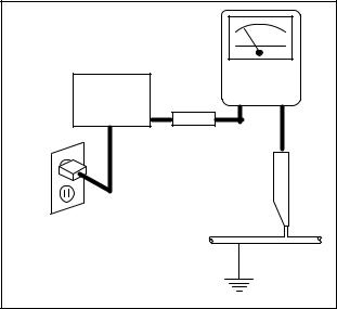
d.Leakage Current Hot Check - With the instrument completely reassembled, plug the
AC line cord directly into a 120 V AC outlet. (Do not use an isolation transformer during this test.) Use a leakage current tester or a metering system that complies with American National Standards Institute (ANSI) C101.1 Leakage Current for Appliances and Underwriters Laboratories (UL) 1410, (50.7). With the instrument AC switch first in the on position and then in the off position, measure from a known earth ground (metal water pipe, conduit, etc.) to all exposed metal parts of the instrument (antennas, handle brackets, metal cabinet, screw heads, metallic overlays, control shafts, etc.), especially any exposed metal parts that offer an electrical return path to the chassis. Any current measured must not exceed 0.5 milli-ampere. Reverse the instrument power cord plug in the outlet and repeat the test.
READING SHOULD |
|
|
|
NOT BE ABOVE 0.5 mA |
|
|
|
|
LEAKAGE |
||
DEVICE |
CURRENT |
||
BEING |
TESTER |
||
|
_ |
||
TESTED |
+ |
||
|
|||
TEST ALL EXPOSED |
|||
METAL SURFACES |
|
||
ALSO TEST WITH |
|
|
|
PLUG REVERSED |
|
|
|
USING AC |
|
EARTH |
|
ADAPTER PLUG |
|
||
AS REQUIRED |
|
GROUND |
|
ANY MEASUREMENTS NOT WITHIN THE LIMITS SPECIFIED HEREIN INDICATE A POTENTIAL SHOCK HAZARD THAT MUST BE ELIMINATED BEFORE RETURNING THE INSTRUMENT TO THE CUSTOMER OR BEFORE CONNECTING THE ANTENNA OR ACCESSORIES.
e.X-Radiation and High Voltage Limits -
Because the picture tube is the primary potential source of X-radiation in solid-state TV receivers, it is specially constructed to prohibit X-radiation emissions. For continued X- radiation protection, the replacement picture tube must be the same type as the original.
1-3-1 |
TVDVDN_ISP |
Also, because the picture tube shields and mounting hardware perform an X-radiation protection function, they must be correctly in place. High voltage must be measured each time servicing is performed that involves B+, horizontal deflection or high voltage. Correct operation of the X-radiation protection circuits also must be reconfirmed each time they are serviced. (X-radiation protection circuits also may be called “horizontal disable” or “hold down.”) Read and apply the high voltage limits and, if the chassis is so equipped, the X- radiation protection circuit specifications given on instrument labels and in the Product Safety & X-Radiation Warning note on the service data chassis schematic. High voltage is maintained within specified limits by close tolerance safety-related components/ adjustments in the high-voltage circuit. If high voltage exceeds specified limits, check each component specified on the chassis schematic and take corrective action.
2.Read and comply with all caution and safetyrelated notes on or inside the receiver cabinet, on the receiver chassis, or on the picture tube.
3.Design Alteration Warning - Do not alter or add to the mechanical or electrical design of this TV receiver. Design alterations and additions, including, but not limited to circuit modifications and the addition of items such as auxiliary audio and/or video output connections, might alter the safety characteristics of this receiver and create a hazard to the user. Any design alterations or additions will void the manufacturer's warranty and may make you, the servicer, responsible for personal injury or property damage resulting therefrom.
4.Picture Tube Implosion Protection Warning -
The picture tube in this receiver employs integral implosion protection. For continued implosion protection, replace the picture tube only with one of the same type number. Do not remove, install, or otherwise handle the picture tube in any manner without first putting on shatterproof goggles equipped with side shields. People not so equipped must be kept safely away while picture tubes are handled. Keep the picture tube away from your body. Do not handle the picture tube by its neck. Some “in-line” picture tubes are equipped with a permanently attached deflection yoke; because of potential hazard, do not try to remove such “permanently attached” yokes from the picture tube.
5.Hot Chassis Warning -
a.Some TV receiver chassis are electrically connected directly to one conductor of the AC power cord and maybe safety-serviced without
an isolation transformer only if the AC power plug is inserted so that the chassis is connected to the ground side of the AC power source. To confirm that the AC power plug is inserted correctly, with an AC voltmeter, measure between the chassis and a known earth ground. If a voltage reading in excess of 1.0V is obtained, remove and reinsert the AC power plug in the opposite polarity and again measure the voltage potential between the chassis and a known earth ground.
b.Some TV receiver chassis normally have 85V AC(RMS) between chassis and earth ground regardless of the AC plug polarity. This chassis can be safety-serviced only with an isolation transformer inserted in the power line between the receiver and the AC power source, for both personnel and test equipment protection.
c.Some TV receiver chassis have a secondary ground system in addition to the main chassis ground. This secondary ground system is not isolated from the AC power line. The two ground systems are electrically separated by insulation material that must not be defeated or altered.
6.Observe original lead dress. Take extra care to assure correct lead dress in the following areas: a. near sharp edges, b. near thermally hot parts-be sure that leads and components do not touch thermally hot parts, c. the AC supply, d. high voltage, and, e. antenna wiring. Always inspect in all areas for pinched, out of place, or frayed wiring. Check AC power cord for damage.
7.Components, parts, and/or wiring that appear to have overheated or are otherwise damaged should be replaced with components, parts, or wiring that meet original specifications. Additionally, determine the cause of overheating and/or damage and, if necessary, take corrective action to remove any potential safety hazard.
8.Product Safety Notice - Some electrical and mechanical parts have special safety-related characteristics which are often not evident from visual inspection, nor can the protection they give necessarily be obtained by replacing them with components rated for higher voltage, wattage, etc. Parts that have special safety characteristics are identified by a # on schematics and in parts lists. Use of a substitute replacement that does not have the same safety characteristics as the recommended replacement part might create shock, fire, and/or other hazards. The product's safety is under review continuously and new instructions are issued whenever appropriate. Prior to shipment from the factory, our products are strictly inspected to confirm they comply with the recognized product safety and electrical codes
1-3-2 |
TVDVDN_ISP |
of the countries in which they are to be sold. However, in order to maintain such compliance, it is equally important to implement the following precautions when a set is being serviced.
Precautions during Servicing
A.Parts identified by the # symbol are critical for safety.
Replace only with part number specified.
B.In addition to safety, other parts and assemblies are specified for conformance with regulations applying to spurious radiation. These must also be replaced only with specified replacements. Examples: RF converters, RF cables, noise blocking capacitors, and noise blocking filters, etc.
C.Use specified internal wiring. Note especially:
1)Wires covered with PVC tubing
2)Double insulated wires
3)High voltage leads
D.Use specified insulating materials for hazardous live parts. Note especially:
1)Insulation Tape
2)PVC tubing
3)Spacers
4)Insulators for transistors.
E.When replacing AC primary side components (transformers, power cord, etc.), wrap ends of wires securely about the terminals before soldering.
F.Observe that the wires do not contact heat producing parts (heat sinks, oxide metal film resistors, fusible resistors, etc.)
G.Check that replaced wires do not contact sharp edged or pointed parts.
H.When a power cord has been replaced, check that 5~6 kg of force in any direction will not loosen it.
I.Also check areas surrounding repaired locations.
J.Be careful that foreign objects (screws, solder droplets, etc.) do not remain inside the set.
K.Crimp type wire connector
When replacing the power transformer in sets where the connections between the power cord and power transformer primary lead wires are performed using crimp type connectors, in order to prevent shock hazards, perform carefully and precisely the following steps.
Replacement procedure
1)Remove the old connector by cutting the wires at a point close to the connector.
Important: Do not re-use a connector (discard it).
2)Strip about 15 mm of the insulation from the ends of the wires. If the wires are stranded, twist the strands to avoid frayed conductors.
3)Align the lengths of the wires to be connected. Insert the wires fully into the connector.
4)Use the crimping tool to crimp the metal sleeve at the center position. Be sure to crimp fully to the complete closure of the tool.
L.When connecting or disconnecting the DVD/VCR connectors, first, disconnect the AC plug from the AC supply socket.
1-3-3 |
TVDVDN_ISP |
Safety Check after Servicing
Examine the area surrounding the repaired location for damage or deterioration. Observe that screws, parts and wires have been returned to original positions. Afterwards, perform the following tests and confirm the specified values in order to verify compliance with safety standards.
1. Clearance Distance
When replacing primary circuit components, confirm |
|
|
|||
specified clearance distance (d) and (d') between |
Chassis or Secondary Conductor |
||||
soldered terminals, and between terminals and |
|||||
|
|
||||
surrounding metallic parts. (See Fig. 1) |
|
|
|||
Table 1: Ratings for selected area |
|
Primary Circuit |
|||
|
|
||||
AC Line Voltage |
Region |
Clearance |
d' |
d |
|
Distance (d), (d’) |
|
|
|||
|
|
|
|
||
110 to 130 V |
U.S.A. or |
≥ 3.2 mm |
|
|
|
Canada |
(0.126 inches) |
|
|
||
|
|
|
|||
Note: This table is unofficial and for reference only. Be |
|
|
|||
sure to confirm the precise values. |
|
|
|||
Fig. 1
2. Leakage Current Test
Confirm the specified (or lower) leakage current between B (earth ground, power cord plug prongs) and externally exposed accessible parts (RF terminals, antenna terminals, video and audio input and output terminals, microphone jacks, earphone jacks, etc.).
Measuring Method: (Power ON)
Insert load Z between B (earth ground, power cord plug prongs) and exposed accessible parts. Use an AC voltmeter to measure across both terminals of load Z. See Fig. 2 and following table.
Table 2: Leakage current ratings for selected areas
 Exposed Accessible Part
Z
AC Voltmeter
(High Impedance)
BEarth Ground
Power Cord Plug Prongs
Fig. 2
AC Line Voltage |
Region |
Load Z |
Leakage Current (i) |
Earth Ground (B) to: |
|
|
|
|
|
|
|
|
|
|
|
|
|
110 to 130 V |
U.S.A. or |
0.15 µF CAP. & 1.5 kΩ |
i ≤ 0.5 mA rms |
Exposed accessible |
|
Canada |
RES. Connected in parallel |
parts |
|||
|
|
||||
|
|
|
|
|
Note: This table is unofficial and for reference only. Be sure to confirm the precise values.
1-3-4 |
TVDVDN_ISP |
STANDARD NOTES FOR SERVICING
Circuit Board Indications
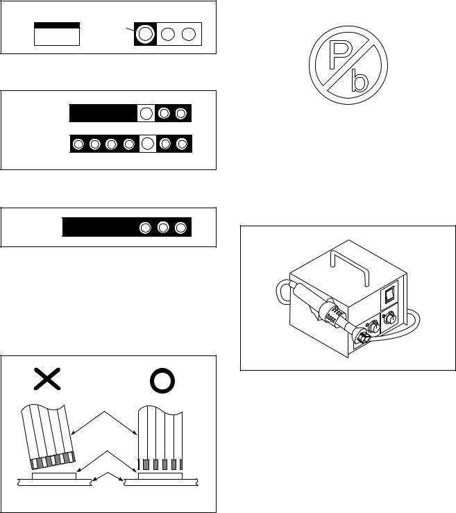
1.The output pin of the 3 pin Regulator ICs is indicated as shown.
Top View |
Bottom View |
Out |
Input |
In |
2.For other ICs, pin 1 and every fifth pin are indicated as shown.
5
Pin 1 


10
3.The 1st pin of every male connector is indicated as shown.
Pin 1 


Instructions for Connectors
1.When you connect or disconnect the FFC (Flexible Foil Connector) cable, be sure to first disconnect the AC cord.
2.FFC (Flexible Foil Connector) cable should be inserted parallel into the connector, not at an angle.
FFC Cable
Connector
CBA
* Be careful to avoid a short circuit.
Pb (Lead) Free Solder
Pb free mark will be found on PCBs which use Pb free solder. (Refer to figure.) For PCBs with Pb free mark, be sure to use Pb free solder. For PCBs without Pb free mark, use standard solder.
Pb free mark
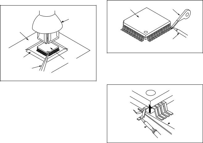
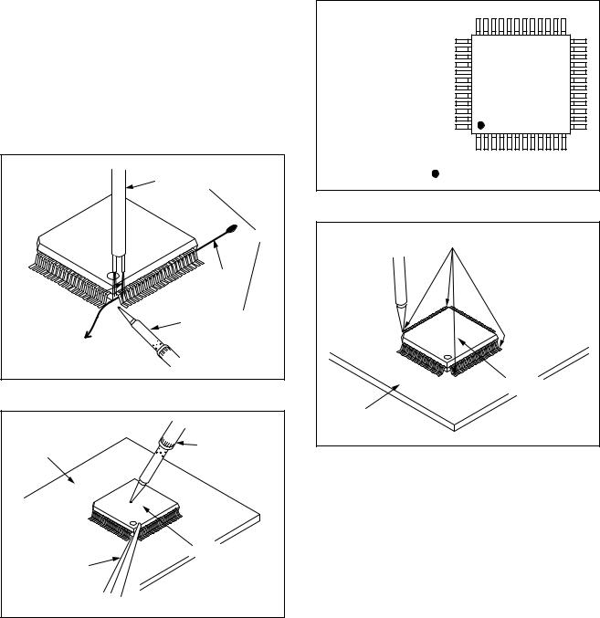
How to Remove / Install Flat Pack-IC
1. Removal
With Hot-Air Flat Pack-IC Desoldering Machine:
1.Prepare the hot-air flat pack-IC desoldering machine, then apply hot air to the Flat Pack-IC (about 5 to 6 seconds). (Fig. S-1-1)
Fig. S-1-1
2.Remove the flat pack-IC with tweezers while applying the hot air.
3.Bottom of the flat pack-IC is fixed with glue to the CBA; when removing entire flat pack-IC, first apply soldering iron to center of the flat pack-IC and heat up. Then remove (glue will be melted). (Fig. S-1-6)
4.Release the flat pack-IC from the CBA using tweezers. (Fig. S-1-6)
CAUTION:
1.The Flat Pack-IC shape may differ by models. Use an appropriate hot-air flat pack-IC desoldering machine, whose shape matches that of the Flat Pack-IC.
2.Do not supply hot air to the chip parts around the flat pack-IC for over 6 seconds because damage to the chip parts may occur. Put masking tape
1-4-1 |
TVDVDN_SN |
around the flat pack-IC to protect other parts from damage. (Fig. S-1-2)
3.The flat pack-IC on the CBA is affixed with glue, so be careful not to break or damage the foil of each pin or the solder lands under the IC when removing it.
|
Hot-air |
|
Flat Pack-IC |
|
Desoldering |
CBA |
Machine |
|
|
Masking |
Flat Pack-IC |
Tape |
|
Tweezers |
|
|
Fig. S-1-2 |
With Soldering Iron:
1.Using desoldering braid, remove the solder from all pins of the flat pack-IC. When you use solder flux which is applied to all pins of the flat pack-IC, you can remove it easily. (Fig. S-1-3)
Flat Pack-IC |
Desoldering Braid |
|
Soldering Iron
Fig. S-1-3
2.Lift each lead of the flat pack-IC upward one by one, using a sharp pin or wire to which solder will not adhere (iron wire). When heating the pins, use a fine tip soldering iron or a hot air desoldering machine. (Fig. S-1-4)
Sharp
 Pin
Pin
Fine Tip 
Soldering Iron
Fig. S-1-4
3.Bottom of the flat pack-IC is fixed with glue to the CBA; when removing entire flat pack-IC, first apply soldering iron to center of the flat pack-IC and heat up. Then remove (glue will be melted). (Fig. S-1-6)
4.Release the flat pack-IC from the CBA using tweezers. (Fig. S-1-6)
1-4-2 |
TVDVDN_SN |
With Iron Wire:
1.Using desoldering braid, remove the solder from all pins of the flat pack-IC. When you use solder flux which is applied to all pins of the flat pack-IC, you can remove it easily. (Fig. S-1-3)
2.Affix the wire to a workbench or solid mounting point, as shown in Fig. S-1-5.
3.While heating the pins using a fine tip soldering iron or hot air blower, pull up the wire as the solder melts so as to lift the IC leads from the CBA contact pads as shown in Fig. S-1-5.
4.Bottom of the flat pack-IC is fixed with glue to the CBA; when removing entire flat pack-IC, first apply soldering iron to center of the flat pack-IC and heat up. Then remove (glue will be melted). (Fig. S-1-6)
5.Release the flat pack-IC from the CBA using tweezers. (Fig. S-1-6)
Note: When using a soldering iron, care must be taken to ensure that the flat pack-IC is not being held by glue. When the flat pack-IC is removed from the CBA, handle it gently because it may be damaged if force is applied.
Hot Air Blower |
or |
Iron Wire |
Soldering Iron |
To Solid |
Mounting Point |
Fig. S-1-5 |
CBA |
Fine Tip |
Soldering Iron |
|
|
Flat Pack-IC |
Tweezers |
|
|
Fig. S-1-6 |
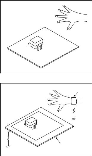
2. Installation
1.Using desoldering braid, remove the solder from the foil of each pin of the flat pack-IC on the CBA so you can install a replacement flat pack-IC more easily.
2.The “●” mark on the flat pack-IC indicates pin 1. (See Fig. S-1-7.) Be sure this mark matches the 1 on the PCB when positioning for installation. Then presolder the four corners of the flat pack-IC. (See Fig. S-1-8.)
3.Solder all pins of the flat pack-IC. Be sure that none of the pins have solder bridges.
Example :
Pin 1 of the Flat Pack-IC |
|
is indicated by a " " mark. |
Fig. S-1-7 |
|
Presolder |
Flat Pack-IC |
CBA |
Fig. S-1-8 |
1-4-3 |
TVDVDN_SN |
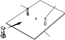
Instructions for Handling Semiconductors
Electrostatic breakdown of the semi-conductors may occur due to a potential difference caused by electrostatic charge during unpacking or repair work.
1. Ground for Human Body
Be sure to wear a grounding band (1 MΩ) that is properly grounded to remove any static electricity that may be charged on the body.
2. Ground for Workbench
Be sure to place a conductive sheet or copper plate with proper grounding (1 MΩ) on the workbench or other surface, where the semi-conductors are to be placed. Because the static electricity charge on clothing will not escape through the body grounding band, be careful to avoid contacting semi-conductors with your clothing.
<Incorrect> |
|
|
CBA |
<Correct> |
Grounding Band |
|
1MΩ |
|
CBA |
1MΩ |
|
Conductive Sheet or
Copper Plate
1-4-4 |
TVDVDN_SN |
PREPARATION FOR SERVICING
How to Enter Service Mode
Caution 1:
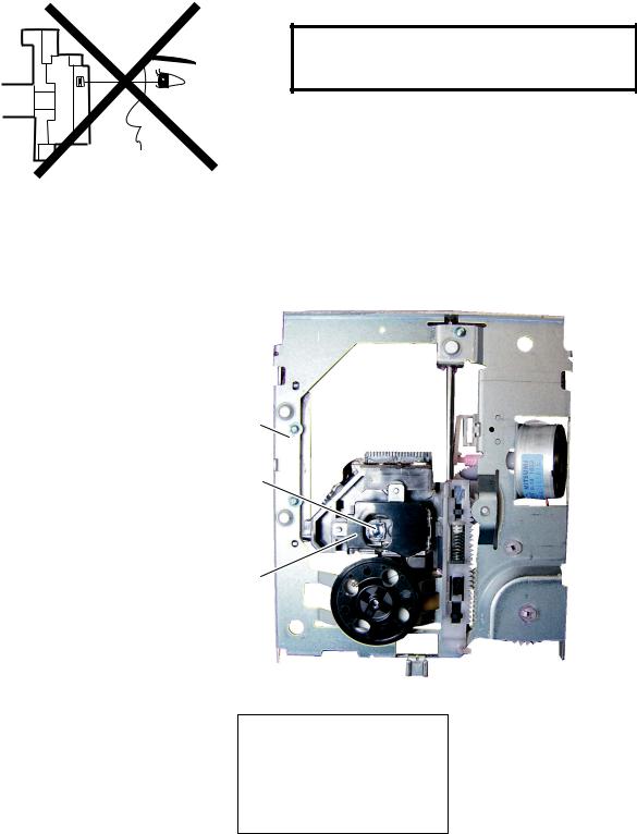
1.Optical sensors system are used for Tape Start and End Sensor on this equipment. Read this page carefully and prepare as described on this page before starting to service; otherwise, the unit may operate unexpectedly.
Preparing 1:
1.Cover Q1202 (START SENSOR) and Q1201 (END SENSOR) with Insulation Tape or enter the service mode to activate Sensor Inhibition automatically.
Note: Avoid playing, rewinding or fast forwarding the tape to its beginning or end, because both Tape End Sensors are not active.
How to Enter the Service Mode
1.Turn the power on.
2.Use the service remote control unit and press [DISC MENU] button.
3.When entering the service mode, one of the number (1, 2 or 4) will be displayed at corners of the screen.
4.During Service mode, electrical adjustment mode can be selected by the service remote control unit key.
Details are as follows.
Key |
Adjustment Mode |
|
|
|
|
|
|
|
|
Picture adjustment mode in TV mode or |
|
|
DTV mode: |
|
|
Press the [PICTURE] button to change |
|
PICTURE |
from BRT (Bright), *CNT (Contrast), |
|
*COL (Color), *TNT(Tint), *V-T(V-Tint) |
||
|
and *SHP (Sharpness). Press [CH. o/ |
|
|
p] buttons to display Initial Value. |
|
|
*Marked items are not necessary to |
|
|
adjust normally. |
|
|
|
|
0 |
C-Trap adjustment mode in TV mode: |
|
See adjustment instructions. |
||
|
||
|
|
|
1 |
No need to use. |
|
|
|
|
2 |
H f0 adjustment mode: |
|
|
See adjustment instructions. |
|
3 |
U-/V-Pedestal adjustment mode in DTV |
|
mode: |
||
|
See adjustment instructions. |
|
|
|
|
4 |
Auto record mode: |
|
Perform recording (15 Sec.) --> Stop --> |
||
|
Rewind (Zero return) automatically. |
|
|
|
Key |
Adjustment Mode |
|
|
|
|
|
|
|
5 |
Head switching position adjustment: |
|
See adjustment instructions. |
||
|
||
|
|
|
6 |
YUV Brightness up adjustment mode in |
|
DTV mode: |
||
|
See adjustment instructions. |
|
|
|
|
|
Purity check mode: |
|
7 |
Shows Red, Green, Blue or White |
|
cyclically on the screen each time the |
||
|
||
|
[7] button is pressed. |
|
|
|
|
8 |
H. Position adjustment: |
|
See adjustment instructions. |
||
|
||
|
|
|
9 |
V. Position/V. Size adjustment: |
|
See adjustment instructions. |
||
|
||
|
|
|
VOL m |
No need to use. |
|
|
|
|
|
Cut-off/Drive adjustment: |
|
VOL n |
See adjustment instructions. |
|
White balance adjustment: |
||
|
||
|
See adjustment instructions. |
|
|
|
Caution 2:
1.The deck mechanism assembly is mounted on the Main CBA directly, and SW1211 (REC-SAFETY SW) is mounted on the Main CBA. When deck mechanism assembly is removed from the Main CBA due to servicing, this switch can not be operated automatically.
Preparing 2:
1.To eject the tape, press the [STOP/EJECT] button on the unit (or remote control).
2.When you want to record during Service mode, press the [REC] button while depressing SW1211 (REC-SAFETY SW) on the Main CBA.
Q1201 |
Q1202 |
(END SENSOR) |
(START SENSOR) |
MAIN CBA
SW1211 (REC-SAFETY SW)
1-5-1 |
P7753PFS |
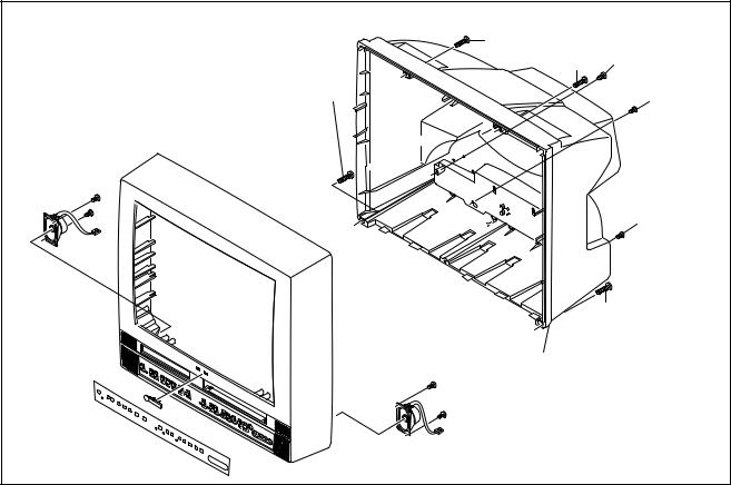
CABINET DISASSEMBLY INSTRUCTIONS
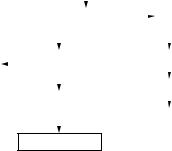
1. Disassembly Flowchart
This flowchart indicates the disassembly steps for the cabinet parts, and the CBA in order to gain access to item(s) to be serviced. When reassembling, follow the steps in reverse order. Bend, route and dress the cables as they were.
CAUTION!
When removing the CRT, be sure to discharge the Anode Lead of the CRT with the CRT Ground Wire before removing the Anode Cap.
|
|
|
|
|
[1] Rear Cabinet |
|
|
|
|
|
|
|||||
|
|
|
|
|
|
|
|
|
|
|
|
|
|
|
|
|
|
|
|
|
|
|
|
|
|
|
|
|
|
|
|
|
|
|
|
|
|
|
|
|
|
|
|
|
|
|
|
|
|
|
|
|
|
|
[2] Tray Chassis Unit |
|
|
[3] CRT |
|
||||||||
|
|
|
|
|
|
|
||||||||||
|
|
|
|
|
|
|
|
|
|
|
|
|
|
|
|
|
|
|
|
|
|
|
|
|
|
|
|
|
|
||||
|
|
|
|
|
|
|
|
|
|
|
|
|
|
|
|
|
|
|
|
|
|
|
|
|
|
|
|
|
|||||
|
|
|
|
[4] DVD |
|
|
|
[8] Deck Assembly |
|
|||||||
[7] Function CBA |
|
|
|
|
|
|
|
|||||||||
|
|
Mechanism |
|
|
|
|
|
|
|
|
|
|||||
|
|
|
|
|
|
|
|
|
|
|
|
|
|
|
|
|
|
|
|
|
|
|
|
|
|
|
|
|
[9] Main CBA |
|
|||
|
|
|
|
|
|
|
|
|
|
|
|
|
||||
|
|
|
[5] DVD Main |
|
|
|
|
|
|
|
|
|
||||
|
|
|
|
CBA Unit |
|
|
|
|
|
|
|
|
|
|||
|
|
|
|
|
|
|
[10] DTV Module |
|
||||||||
|
|
|
|
|
|
|
|
|
|
|
|
|||||
|
|
|
|
|
|
|
|
|
|
|
|
CBA Unit |
|
|||
|
|
|
|
|
|
|
|
|
|
|
|
|
||||
[6]Sub CBA
2.Disassembly Method
|
|
|
Removal |
|
|
Step/ |
|
|
|
|
|
|
|
Remove/*Unhook/ |
|
||
Loc. |
Part |
|
|
||
Fig. |
Unlock/Release/ |
Note |
|||
No. |
|
||||
|
No. |
Unplug/Unclamp/ |
|||
|
|
|
|||
|
|
|
Desolder |
|
|
|
|
|
|
|
|
|
|
|
|
|
|
[1] |
Rear |
D1 |
4(S-1), (S-2), (S-3A), |
--- |
|
Cabinet |
(S-3B) |
||||
|
|
|
|
|
|
|
Tray |
D2 |
Anode Cap, *CN2501, |
|
|
[2] |
CRT CBA, *CN1601, |
1 |
|||
Chassis |
D3 |
*CN2571, *CN3801, |
|||
|
Unit |
D5 |
|
||
|
*CN3802 |
|
|||
|
|
|
|
|
|
[3] |
CRT |
D3 |
4(S-4) |
--- |
|
|
|
|
|
|
|
|
DVD |
D2 |
4(S-5), *CN201, |
|
|
[4] |
D4 |
2, 3 |
|||
|
Mechanism |
D5 |
*CN301 |
|
|
|
|
|
|
|
|
|
DVD Main |
D2 |
|
|
|
[5] |
D4 |
*CN1, *CN2 |
--- |
||
CBA Unit |
|||||
|
D5 |
|
|
||
|
|
|
|
||
|
|
|
|
|
|
[6] |
Sub CBA |
D2 |
6(S-6), *CN1103, |
--- |
|
D5 |
*CN1301, *CN1302 |
||||
|
|
|
|||
|
|
|
|
|
|
[7] |
Function |
D2 |
(S-7), *CN2401 |
--- |
|
CBA |
D5 |
||||
|
|
|
|
|
|
|
|
|
3(S-8), Top Shield, |
|
|
[8] |
Deck |
D2 |
7(S-9), (S-10), (S-11), |
4 |
|
Assembly |
D5 |
*CL1201, *CL1401, |
|||
|
|
||||
|
|
|
*CL1402, *CL1403 |
|
|
|
|
|
|
|
|
|
|
Removal |
|
|
Step/ |
|
|
|
|
|
|
|
Remove/*Unhook/ |
|
||
Loc. |
Part |
|
|
||
Fig. |
Unlock/Release/ |
Note |
|||
No. |
|
||||
|
No. |
Unplug/Unclamp/ |
|||
|
|
|
Desolder |
|
|
|
|
|
|
|
|
|
|
|
|
|
|
[9] |
Main CBA |
D2 |
4(S-12) |
--- |
|
D5 |
|||||
|
|
|
|
|
|
|
DTV |
D2 |
*CN1101, *CN1102 |
|
|
[10] |
Module |
--- |
|||
D5 |
Module PCB Holder |
||||
|
CBA Unit |
|
|||
|
|
|
|
||
|
|
|
|
|
|
↓ |
↓ |
↓ |
↓ |
↓ |
|
(1) |
(2) |
(3) |
(4) |
(5) |
Note:
(1)Order of steps in procedure. When reassembling, follow the steps in reverse order. These numbers are also used as the Identification (location) No. of parts in figures.
(2)Parts to be removed or installed.
(3)Fig. No. showing procedure of part location
(4)Identification of parts to be removed, unhooked, unlocked, released, unplugged, unclamped, or desoldered.
P = Spring, L = Locking Tab, S = Screw, CN = Connector
*= Unhook, Unlock, Release, Unplug, or Desolder e.g. 2(S-2) = two Screws (S-2),
2(L-2) = two Locking Tabs (L-2)
(5)Refer to the following “Reference Notes in the Table”.
1-6-1 |
P7752DC |
Reference Notes in the Table
CAUTION!
When removing the CRT, be sure to discharge the Anode Lead of the CRT with the CRT Ground Wire before removing the Anode Cap.
1.CAUTION 1: Discharge the Anode Lead of the CRT with the CRT Ground Wire before removing the Anode Cap.
Disconnect the following: Anode Cap, CN2501, CRT CBA, CN1601, CN2571, CN3801 and CN3802. Then remove Tray Chassis Unit.
2.CAUTION 2: Electrostatic breakdown of the laser diode in the optical system block may occur as a potential difference caused by electrostatic charge accumulated on cloth, human body etc., during unpacking or repair work.
To avoid damage of pickup follow the next procedures.
1)Disconnect Connector (CN301) on the DVD Main CBA Unit.
2)Short the three short lands of the FPC cable with solder before removing the FFC cable (CN201). If you disconnect the FFC cable (CN201) without shorting them, the laser diode of pickup will be destroyed. (Fig. D4)
3)Remove DVD Mechanism.
3.CAUTION 3: When reassembling, confirm the FFC cable (CN201) is connected completely. Then remove the solder from the three short lands of the FPC cable. (Fig. D4)
4.Remove screws 3(S-8) and remove Top Shield. Remove screws 7(S-9), (S-10) and (S-11). Then, desolder connectors (CL1201, CL1401, CL1402, CL1403) and lift up the Deck Assembly.
(S-1) |
|
(S-1) |
(S-2) |
(S-1) |
(S-3A) |
|
|
|
(S-3B) |
(S-1) |
|
[1] Rear Cabinet |
|
|
Fig. D1 |
1-6-2 |
P7752DC |

|
|
|
[2] Tray Chassis Unit |
|
|
(S-5) |
|
(S-8) |
Top Shield |
|
|
|
|
|
|||
|
(S-5) |
|
|
||
|
|
|
|
|
|
|
[4] DVD |
|
|
(S-8) |
|
|
Mechanism |
|
|
|
|
|
(S-9) |
|
(S-9) |
|
|
|
|
|
|
|
|
|
|
|
|
(S-9) |
|
|
[5] DVD Main |
[8] Deck |
Module PCB Holder |
||
|
|
|
|||
|
CBA Unit |
Assembly |
|
|
|
|
(S-6) |
|
(S-12) |
||
|
(S-12) |
|
|||
|
(S-6) |
|
|||
|
|
|
|||
|
|
|
|
|
|
(S-7) |
(S-6) |
|
|
|
[10] DTV |
|
|
|
|
|
Module |
|
|
|
|
|
CBA Unit |
[7] Function |
[6] Sub CBA |
|
|
|
|
|
|
|
[9] Main CBA |
|
|
CBA |
|
(S-10) |
|
|
|
|
(S-12) |
|
|
||
|
|
(S-11) |
|
||
|
|
|
|
|
|
|
|
|
|
|
Fig. D2 |
|
1-6-3 |
|
|
P7752DC |
|

|
|
Anode Cap |
|
(S-4) |
CRT CBA |
(S-4) |
|
|
|
|
(S-4) |
|
[3] CRT |
(S-4) |
|
|
Fig. D3 |
DVD Mechanism |
A |
|
|
|
Short the three short lands by soldering. (Either of two places.)
FPC Cable View for A
Fig. D4
1-6-4 |
P7752DC |
|
|
|
DVD Main CBA Unit |
||
|
|
Junction-B |
CN301 |
|
|
|
|
CBA |
CN201 |
|
|
|
|
TO SPEAKER |
CN2A CN1A |
|
|
|
|
|
|
||
ANODE |
|
CL3801 |
|
|
|
|
CN3801 |
|
|
|
|
|
|
|
|
|
|
CRT |
|
CN2801 |
|
|
|
|
|
|
|
|
|
GND |
|
|
|
|
|
|
|
Function |
CN2571 |
|
|
|
|
CBA |
|
CL2501A |
|
|
|
|
|
||
|
|
Sub CBA |
CN2 |
CN1 CL2504A |
|
|
|
|
|||
|
|
CN2401 |
CN2301 CN2302 CN2103 |
||
|
|
|
|||
|
SCREEN FOCUS |
Main CBA |
|
|
|
|
CL1403 |
CN1301 CN1302 CN1103 |
|||
|
|
||||
CL2504B |
|
CN1104 |
|||
|
|
|
|
||
|
|
|
|
|
|
CRT CBA |
|
CN2501 |
|
|
|
|
|
CL1401 |
|
|
|
|
|
|
|
|
|
|
CL2501B |
|
|
AC CORD |
|
|
|
|
|
||
|
|
|
CL1402 |
|
|
|
|
|
|
CN1601 |
|
|
|
|
|
|
TUNER |
|
|
CN1802 |
CL1201 |
CN1102 CN1101 |
|
|
|
|
|
|
|
|
ACE HEAD |
CN3802 |
|
|
|
|
ASSEMBLY |
|
|
|
|
|
|
CL3802 |
|
CN102 |
CN101 |
|
|
|
|
||
|
|
TO SPEAKER |
DTV Module CBA Unit |
||
|
|
Junction-A CBA |
|||
FE HEAD |
|
|
|
|
|
|
|
|
|
|
|
|
|
Deck Assembly |
|
|
|
CYLINDER |
CAPSTAN |
|
|
|
|
ASSEMBLY |
|
|
|
|
|
MOTOR |
|
|
|
|
|
|
|
|
|
Fig. D5 |
|
|
|
|
|
|
|
|
|
1-6-5 |
|
|
P7752DC |
ELECTRICAL ADJUSTMENT INSTRUCTIONS
General Note: “CBA” is abbreviation for “Circuit Board Assembly.”
Note: Electrical adjustments are required after replacing circuit components and certain mechanical parts. It is important to perform these adjustments only after all repairs and replacements have been completed.
Also, do not attempt these adjustments unless the proper equipment is available.
Test Equipment Required
1.NTSC Pattern Generator (Color Bar W/White Window, Red Color, Dot Pattern, Gray Scale, Monoscope, Multi-Burst)
2.AC Milli Voltmeter (RMS)
3.Alignment Tape (FL8A, FL8N), Blank Tape
4.DC Voltmeter
5.Oscilloscope: Dual-trace with 10:1 probe, V-Range: 0.001~50 V/Div,
F-Range: DC~AC-60 MHz
6.Frequency Counter
7.Plastic Tip Driver
8.Color Analyzer
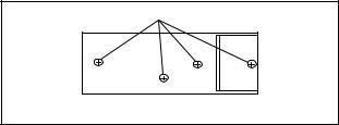
How to make the service remote control unit:
1.Prepare normal remote control unit (Part No. NE204UD or NE209UD). Remove 4 screws from the back lid (Fig. 1).
Screws
Remote control unit (bottom) |
Fig. 1 |
|
2.Cut off pin 10 of the remote control microprocessor and short circuit pins 10 and 17 of the microprocessor with a jumper wire.
How to enter Service mode:
Service mode:
1.Use the service remote control unit.
2.Turn the power on. (Use main power on the TV unit.)
3.To change TV mode, DTV mode, or DVD mode, press [SELECT] button on the TV unit.
4.Press [DISC MENU] button on the service remote control unit.
X-Ray Protection Test
X-Ray protection test should be done when replacing any parts of this chassis.
1.Short both ends of R2592 (on Sub CBA).
2.Confirm that the main power turns off.
3.If the main power does not turn off, then replace the following parts (D2591, Q2591, R2592, R2593, R2594 and IC1201).
4.Perform steps 1 to 3 again.
1. DC 114V (+B) Adjustment
Purpose: To obtain correct operation.
Symptom of Misadjustment: The picture is dark and the unit does not operate correctly.
Test Point |
Adj. Point |
Mode |
Input |
|
|
|
|
|
|
|
|
|
|
|
TP2501(+B) |
VR1601 |
--- |
--- |
|
TP2504(GND) |
||||
|
|
|
||
|
|
|
|
|
Tape |
M. EQ. |
|
Spec. |
|
|
|
|
||
|
|
|
||
--- |
DC Voltmeter |
+114±1.0 V DC |
||
|
|
|
|
|
Note: TP2501(+B), TP2504(GND) --- Sub CBA,
VR1601 --- Main CBA
1.Connect the unit to AC Power Outlet.
2.Connect DC Voltmeter to TP2501(+B) and TP2504(GND).
3.Adjust VR1601 so that the voltage of TP2501(+B) becomes +114±1.0 V DC.
1-7-1 |
P7753EA |
2. Setting for CONTRAST, COLOR, TINT, V-TINT and SHARPNESS Data Values
<TV mode (Composite block)>
1.Enter Service mode in TV mode.
2.Press [PICTURE] button on the service remote control unit. Display changes “BRT,” “CNT,” “COL,” “TNT,” “V-T,” and “SHP” cyclically when [1] button is pressed.
CONTRAST (CNT)
1.Press [1] button to selcet “CONTRAST (CNT)” display.
2.Press [CH. o/p] buttons so that the value of “CONTRAST (CNT)” becomes “80”.
COLOR (COL)
1.Press [1] button to select “COLOR (COL)” display.
2.Press [CH. o/p] buttons so that the value of “COLOR (COL)” becomes “58”.
TINT (TNT)
1.Press [1] button to select “TINT (TNT)” display.
2.Press [CH. o/p] buttons so that the value of “TINT (TNT)” becomes “56”.
V-TINT (V-T)
1.Press [1] button to select “V-TINT (V-T)” display.
2.Press [CH. o/p] buttons so that the value of “V- TINT (V-T)” becomes “50”.
SHARPNESS (SHP)
1.Press [1] button to select “SHARPNESS (SHP)” display.
2.Press [CH. o/p] buttons so that the value of “SHARPNESS (SHP)” becomes “43”.
Note: BRIGHT data value does not need to be adjusted because this setting is performed in other setting.
<DVD mode (Y-C block)>
1.Enter Service mode in DVD mode.
2.Press [PICTURE] button on the service remote control unit. Display changes “YC-BRT,” “YC-CNT,” “YC-COL,” “YC-TNT,” and “YC-SHP” cyclically when [2] button is pressed.
YC-CONTRAST (YC-CNT)
1.Press [2] button to selcet “YC-CONTRAST (YCCNT)” display.
2.Press [CH. o/p] buttons so that the value of “YCCONTRAST (YC-CNT)” becomes “75”.
YC-COLOR (YC-COL)
1.Press [2] button to select “YC-COLOR (YC-COL)” display.
2.Press [CH. o/p] buttons so that the value of “YCCOLOR (YC-COL)” becomes “70”.
YC-TINT (YC-TNT)
1.Press [2] button to select “YC-TINT (YC-TNT)” display.
2.Press [CH. o/p] buttons so that the value of “YCTINT (YC-TNT)” becomes “50”.
YC-SHARPNESS (YC-SHP)
1.Press [2] button to select “YC-SHARPNESS (YCSHP)” display.
2.Press [CH. o/p] buttons so that the value of “YCSHARPNESS (YC-SHP)” becomes “37”.
<DTV mode (YUV block)>
1.Enter Service mode in DTV mode.
2.Press [PICTURE] button on the service remote control unit. Display changes “YUV-BRT,” “YUVCNT,” “YUV-COL,” “YUV-TNT,” and “YUV-SHP” cyclically when [3] button is pressed.
YUV-CONTRAST (YUV-CNT)
1.Press [3] button to selcet “YUV-CONTRAST (YUVCNT)” display.
2.Press [CH. o/p] buttons so that the value of “YUV-CONTRAST (YUV-CNT)” becomes “80”.
YUV-COLOR (YUV-COL)
1.Press [3] button to select “YUV-COLOR (YUVCOL)” display.
2.Press [CH. o/p] buttons so that the value of “YUV-COLOR (YUV-COL)” becomes “58”.
YUV-TINT (YUV-TNT)
1.Press [3] button to select “YUV-TINT (YUV-TNT)” display.
2.Press [CH. o/p] buttons so that the value of “YUV-TINT (YUV-TNT)” becomes “64”.
YUV-SHARPNESS (YUV-SHP)
1.Press [3] button to select “YUV-SHARPNESS (YUV-SHP)” display.
2.Press [CH. o/p] buttons so that the value of “YUV-SHARPNESS (YUV-SHP)” becomes “45”.
1-7-2 |
P7753EA |

3. C-Trap Adjustment
Purpose: To get minimum leakage of the color signal carrier.
Symptom of Misadjustment: If C-Trap Adjustment is incorrect, stripes will appear on the screen.
|
Test Point |
Adj. Point |
Mode |
Input |
|
|
|
|
|
|
|
|
|
|
|
TP1301 |
[CH o / p] |
--- |
Color Bar |
|
(BLUE) |
buttons |
||
|
|
|
||
|
|
|
|
|
|
Tape |
M. EQ. |
Spec. |
|
|
|
|
|
|
|
|
|
--- |
Oscilloscope |
--- |
|
Pattern Generator |
||
|
|
|
|
|
|
|
|
|
|
Figure |
|
minimum
Fig. 2
Note: TP1301(BLUE) --- Sub CBA
1.Connect oscilloscope to TP1301.
2.Input a color bar signal from RF input. Enter Service mode.
3.Enter the Service mode in TV mode.
4.Press [0] button on the service remote control unit and select C-TRAP mode. (Display changes “C- TRP,” “D-T TV,” “D-T EXT,” “Y SW,” “B-S,” “BS2,” and “C-ANG” cyclically when [0] button is pressed.)
5.Press [CH o / p] buttons on the remote control unit so that the carrier leakage B-Out (3.58 MHz) value becomes minimum on the oscilloscope.
4. H f0 Adjustment
Purpose: To get correct horizontal position and size of screen image.
Symptom of Misadjustment: Horizontal position and size of screen image may not be properly displayed.
Test Point |
Adj. Point |
Mode |
Input |
|
|
|
|
|
|
|
|
R2583 |
[CH. o / p] buttons |
Video |
--- |
|
|
|
|
Tape |
M. EQ. |
Spec. |
|
|
|
|
|
|
|
|
|
--- |
Frequency Counter |
15.734 kHz±300 Hz |
|
|
|
|
|
Note: R2583 --- Sub CBA
1.Connect frequency counter to R2583 and ground.
2.Operate the unit for at least 20 minutes.
3.Enter the Service mode in TV mode.
4.Press [2] button on the service remote control unit and select H-ADJ mode.
5.Press [CH. o/p] buttons on the service remote control unit so that the display will change “0” to “7.”
6.At this moment, choose display “0” to “7” when the
frequency counter display is closest to 15.734 kHz
±300 Hz.
1-7-3 |
P7753EA |
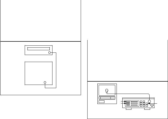
5. Cut-off/Drive Adjustment
Purpose: To adjust the beam current of R, G, B, and screen voltage.
Symptom of Misadjustment: White color may be reddish, greenish or bluish.
|
Test Point |
Adj. Point |
Mode |
Input |
|
|
|
|
|
|
|
|
|
|
|
|
|
|
|
Screen-Control |
|
Black |
|
--- |
[CH. o / p] |
RF |
|||
Raster |
|||||
|
|
buttons |
|
||
|
|
|
|
||
|
|
|
|
|
|
|
Tape |
M. EQ. |
|
Spec. |
|
|
|
|
|
||
|
|
|
|
||
--- |
Pattern |
See Reference |
|||
Generator |
Notes below. |
||||
|
|
||||
|
|
|
|
|
|
Figure
Pattern Generator
RF Input
Fig. 2
Note: Screen Control FBT --- Sub CBA FBT = Fly Back Transformer
Use the service remote control unit
1.Degauss the CRT and allow the unit to operate for 20 minutes before starting the alignment.
2.Input the Black raster signal from RF input.
3.Enter the Service mode in TV mode.
4.Press [VOL n] button on the service remote control to enter "C/D" mode. (Display changes "C/ D," "7f," "TUNER," "SLP R," "MONO," "DTV-H/-H2," "RATING," "RC5" "DL V-CHIP," and "D-SOUND" cyclically when [VOL n] button is pressed.)
5.Press [1] button on the service remote control unit and select "COR" mode.The display will momentarily show "COR". Now there should be a horizontal line across the center of the picture tube. If needed, turn the screen control on the flyback in a clockwise direction gradually until the horizontal line appears. Adjust the Red Cut off by pressing the "[CH. o / p]" buttons. Proceed to Step 6 when the Red Cut off adjustment is done.
6.Press [2] button on the service remote control unit and select "COG" mode. The display will momentarily show "COG". Adjust the Green Cut off by pressing the "[CH. o / p]" buttons. Proceed
to step 7 when the Green Cut off adjustment is done.
7.Press [3] button on the service remote control unit and select "COB" mode. The display will momentarily show "COB". Adjust the Blue cut off by pressing the "[CH. o / p]" buttons. When done with steps 5, 6 and 7 the horizontal line should be pure white, If not, then attempt the Cut off adjustment again.
6. White Balance Adjustment
Purpose: To mix red, green and blue beams correctly for pure white.
Symptom of Misadjustment: White becomes bluish or reddish.
Test Point |
Adj. Point |
Mode |
Input |
||
|
|
|
|
|
|
|
|
|
|
|
|
Screen |
[CH. o/p] |
RF |
White Raster |
||
buttons |
(APL 100%) |
||||
|
|
||||
|
|
|
|
|
|
Tape |
M. EQ. |
|
Spec. |
||
|
|
|
|
|
|
|
|
|
|
|
|
|
Pattern |
|
|
|
|
--- |
Generator, |
See below |
|||
|
Color analyzer |
|
|
|
|
|
|
|
|
|
|
|
Figure |
|
|
|
|
Color Analyzer
Fig. 3
Note: Use the service remote control unit
1.Operate the unit more than 20 minutes.
2.Face the unit to the east. Degauss the CRT using a degaussing coil.
3.Input the White Raster (APL 100%).
4.Set the color analyzer to the CHROMA mode and after zero point calibration, bring the optical receptor to the center on the tube surface (CRT).
5.Enter the Service mode in TV Mode.
6.Press [VOL n] button on the service remote control to enter "C/D" mode. (Display changes "C/ D," "7f," "TUNER," "SLP R," "MONO," "DTV-H/-H2," "RATING," "RC5" "DL V-CHIP," and "D-SOUND" cyclically when [VOL n] button is pressed.)
7.Press [4] button on the service remote control unit for Red adjustment. Press [5] button on the service remote control unit for Blue adjustment.
8.In each color mode, press [CH. o/p] buttons to adjust the values of color.
1-7-4 |
P7753EA |
9.Adjust Red and Blue color so that the temperature becomes 9200K (x: 286 / y: 294) ±3%.
10.At this time, check if horizontal line is white. If not, adjust Cut-off Adjustment until the horizontal line becomes pure white.
11.Turn off and on again to return to the normal mode. Receive APL 100% white signal and confirm that Chroma temperatures become 9200K (x: 286 / y: 294) ±3%.
Note: Confirm that Cut Off Adj. is correct after this adjustment, and attempt Cut Off Adj, if needed.
7. Sub-Brightness Adjustment
Purpose: To get proper brightness.
Symptom of Misadjustment: If Sub-Brightness is incorrect, proper brightness cannot be obtained by adjusting the Brightness Control.
|
Test Point |
Adj. Point |
Mode |
Input |
|
|
|
|
|
|
|
|
|
|
|
|
|
--- |
[CH. o/p] |
RF |
SMPTE |
||
buttons |
7.5IRE |
||||
|
|
|
|||
|
|
|
|
|
|
|
Tape |
M. EQ. |
|
Spec. |
|
|
|
|
|
|
|
|
|
|
|
|
|
--- |
Pattern |
See below |
|||
Generator |
|||||
|
|
|
|
||
|
|
|
|
|
|
|
|
Figure |
|
|
|
White |
Black |
|
|
|
This bar |
|
just |
|
visible |
|
Fig. 4 |
Note: SMPTE Setup level --- 7.5 IRE
1.Enter the Service mode.
Then input SMPTE signal from RF input.
2.Press [PICTURE] button on the service remote control unit.
3.Press [1] button on the service remote control unit and selcet “BRT” mode. (Display changes “BRT,” “CNT,” “COL,” “TNT,” “V-T,” and “SHP” cyclically when [1] button is pressed.)
4.Press [CH o/p] buttons so that the bar is just visible (See above figure).
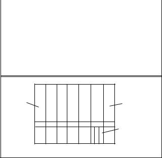
8. Focus Adjustment
Purpose: Set the optimum Focus.
Symptom of Misadjustment: If Focus Adjustment is incorrect, blurred images are shown on the display.
Test Point |
Adj. Point |
Mode |
Input |
|
|
|
|
|
|
|
|
--- |
Focus Control |
--- |
Monoscope |
|
|
|
|
Tape |
M. EQ. |
|
Spec. |
|
|
|
|
|
|
|
|
--- |
Pattern Generator |
See below |
|
|
|
|
|
Note: Focus Control FBT --- Sub CBA
FBT = Fly Back Transformer
1.Operate the unit more than 30 minutes.
2.Face the unit to the East and degauss the CRT using a degaussing coil.
3.Input the monoscope pattern.
4.Adjust the focus control on the FBT to obtain a clear picture.
9. H. Position Adjustment
Purpose: To obtain correct horizontal position of screen image.
Symptom of Misadjustment: H. position may not be properly displayed.
Test Point |
Adj. Point |
Mode |
Input |
|
|
|
|
|
|
|
|
--- |
[CH. o/p] buttons |
--- |
Monoscope |
|
|
|
|
Tape |
M. EQ. |
|
Spec. |
|
|
|
|
|
|
|
|
--- |
Pattern Generator |
|
--- |
|
|
|
|
1.Operate the unit for at least 20 minutes.
2.Enter the Service mode in TV mode.
3.Press [8] button on the service remote control unit and select "H-P" mode.
4.Input monoscope pattern.
5.Press [CH. o / p] buttons on the service remote control unit so that the left and right side of the monoscope pattern are equal to each other.
1-7-5 |
P7753EA |
10. V. Position Adjustment
Purpose: To obtain correct vertical position of screen image.
Symptom of Misadjustment: If V. position is incorrect, vertical position of image on the screen may not be properly displayed.
Test Point |
Adj. Point |
Mode |
Input |
|
|
|
|
|
|
|
|
--- |
[CH. o/p] buttons |
--- |
Monoscope |
|
|
|
|
Tape |
M. EQ. |
|
Spec. |
|
|
|
|
|
|
|
|
--- |
Pattern Generator |
|
--- |
|
|
|
|
1.Operate the unit for at least 20 minutes.
2.Enter the Service mode in TV mode.
3.Press [9] button on the service remote control unit and select "V-P" mode. (Display changes "V-S" and "V-P" cyclically when [9] button is pressed.)
4.Input monoscope pattern.
5.Press [CH. o / p] buttons on the service remote control unit so that the top and bottom of the monoscope pattern are equal each other.
11. V. Size Adjustment
Purpose: To obtain correct vertical height of screen image.
Symptom of Misadjustment: If V. Size is incorrect, vertical height of image on the screen may not be properly displayed.
Test Point |
Adj. Point |
Mode |
Input |
|
|
|
|
|
|
|
|
--- |
[CH. o/p] buttons |
--- |
Monoscope |
|
|
|
|
Tape |
M. EQ. |
|
Spec. |
|
|
|
|
|
|
|
|
--- |
Pattern Generator |
90%±5% |
|
|
|
|
|
1.Operate the unit for at least 20 minutes.
2.Enter the Service mode in TV mode.
3.Press [9] button on the service remote control unit and select V-S mode. (Display changes "V-S" and "V-P" cyclically when [9] button is pressed.)
4.Input monoscope pattern.
5.Press [CH. o / p] buttons on the remote control unit so that the monoscope pattern is 90±5% of display size and the circle is round.
12. Head Switching Position
Adjustment
Purpose: Determine the Head Switching Position during Playback.
Symptom of Misadjustment: May cause Head Switching Noise or Vertical Jitter in the picture.
Note: Unit reads Head Switching Position automatically and displays it on the screen (Upper Left Corner).
1.Playback test tape (VFMS0001H6).
2.Enter the Service mode in TV mode.
3.Press [5] button on the service remote control unit.
4.The Head Switching position will display on the
screen; if adjustment is necessary follow step 4. 6.5H(412.7 s) is preferable.
5.Press [CH. o / p] buttons on the service remote control unit if necessary. The value will be changed in 0.5H steps up or down. Adjustable range is up to 9.5H. If the value is beyond adjustable range, the display will change as: Lower out of range: 0.0H
Upper out of range: -.-H
1-7-6 |
P7753EA |
Loading...