

Mackie DL32R Owner's manual

DL32R Owner’s Manual
Important Safety Instructions
1. Read these instructions.
2. Keep these instructions.
3. Heed all warnings.
4. Follow all instructions.
5. Do not use this apparatus near water.
6. Clean only with a dry cloth.
7. Do not block any ventilation openings. Install in accordance with the manufacturer’s
instructions.
8. Do not install near any heat sources such as radiators, heat registers, stoves, or other
apparatus (including amplifiers) that produce heat.
9. Do not defeat the safety purpose of the polarized or grounding-type plug. A polarized plug
has two blades with one wider than the other. A grounding-type plug has two blades and
a third grounding prong. The wide blade or the third prong are provided for your safety.
If the provided plug does not fit into your outlet, consult an electrician for replacement
of the obsolete outlet.
10. Protect the power cord from being walked on or pinched particularly at plugs, convenience
receptacles, and the point where they exit from the apparatus.
11. Only use attachments/accessories specified by the manufacturer.
12. Unplug this apparatus during lightning storms or when unused for long periods of time.
13. Refer all servicing to qualified service personnel. Servicing is required when the apparatus
has been damaged in any way, such as power-supply cord or plug is damaged, liquid has
been spilled or objects have fallen into the apparatus, the apparatus has been exposed to
rain or moisture, does not operate normally, or has been dropped.
14. This apparatus shall not be exposed to dripping or splashing, and no object filled with liquids,
such as vases or beer glasses, shall be placed on the apparatus.
15. Do not overload wall outlets and extension cords as this can result in a risk of fire or electric
shock.
16. This apparatus has been designed with Class-I construction and must be connected to a mains
socket outlet with a protective earthing connection (the third grounding prong).
CAUTION
RISK OF ELECTRIC SHOCK! DO NOT OPEN!
CAUTION: TO REDUCE THE RISK OF ELECTRIC SHOCK DO
NOT REMOVE COVER (OR BACK). NO USER-SERVICEABLE
PARTS INSIDE. REFER SERVICING TO QUALIFIED PERSONNEL.
The lightning flash with arrowhead symbol within an
equilateral triangle is intended to alert the user to the
prescence of uninsulated “dangerous voltage” within the
product’s enclosure, that may be of significant magnitude
to constitute a risk of electric shock to persons.
The exclamation point within an equilateral triangle is
intended to alert the user of the prescence of important
operating and maintaining (servicing) instructions in the
literature accompanying the appliance.
The DL32R is cooled with two fans on the rear of the unit. Air is drawn in through
the sides and sloping part of the top panel, and is expelled through the rear fan
openings. Always maintain at least four inches clearance behind, and one inch
clearance on each side of the unit.
When installing into a rack, the rear should be open with at least four inches
of clearance behind the rack and adjacent structures (maintaining the one
inch clearance on each side of the unit within the rack). For racks with only
front ventilation, leave at least one rack space open above and below the unit
(maintaining the one inch side and four inch rear clearances around the unit
within the rack).
17. This apparatus has been equipped with an all-pole, rocker-style AC mains power switch.
This switch is located on the rear panel and should remain readily accessible to the user.
18. NOTE: This equipment has been tested and found to comply with the limits for a Class B
digital device, pursuant to part 15 of the FCC Rules. These limits are designed to provide
reasonable protection against harmful interference in a residential installation. This
equipment generates, uses, and can radiate radio frequency energy and, if not installed
and used in accordance with the instructions, may cause harmful interference to radio
communications. However, there is no guarantee that interference will not occur in a
particular installation.
If this equipment does cause harmful interference to radio or television reception, which
can be determined by turning the equipment off and on, the user is encouraged to try to
correct the interference by one or more of the following measures:
• Reorient or relocate the receiving antenna.
• Increase the separation between the equipment and the receiver.
• Connect the equipment into an outlet on a circuit different from that to which the
receiver is connected.
• Consult the dealer or an experienced radio/TV technician for help.
CAUTION: Changes or modifications to this device not expressly approved by LOUD
Technologies Inc. could void the user's authority to operate the equipment under FCC rules.
19. This apparatus does not exceed the Class A/Class B (whichever is applicable) limits for
radio noise emissions from digital apparatus as set out in the radio interference regulations
of the Canadian Department of Communications.
ATTENTION — Le présent appareil numérique n’émet pas de bruits radioélectriques
dépassant las limites applicables aux appareils numériques de class A/de class B (selon le
cas) prescrites dans le réglement sur le brouillage radioélectrique édicté par les ministere
des communications du Canada.
20. Exposure to extremely high noise levels may cause permanent hearing loss. Individuals
vary considerably in susceptibility to noise-induced hearing loss, but nearly everyone will
lose some hearing if exposed to sufficiently intense noise for a period of time. The U.S.
Government’s Occupational Safety and Health Administration (OSHA) has specified the
permissible noise level exposures shown in the following chart.
According to OSHA, any exposure in excess of these permissible limits could result in some
hearing loss. To ensure against potentially dangerous exposure to high sound pressure
levels, it is recommended that all persons exposed to equipment capable of producing
high sound pressure levels use hearing protectors while the equipment is in operation. Ear
plugs or protectors in the ear canals or over the ears must be worn when operating the
equipment in order to prevent permanent hearing loss if exposure is in excess of the limits
set forth here:
Duration,
per day in
hours
8 90 Duo in small club
6 92
4 95 Subway Train
3 97
2 100 Very loud classical music
1.5 102
1 105 Ben screaming at Troy about deadlines
0.5 110
0.25 or less 115 Loudest parts at a rock concert
Sound Level dBA,
Slow Response
Typical Example
WARNING — To reduce the risk of fire or electric shock,
do not expose this apparatus to rain or moisture.
Laite on liitettävä suojakoskettimilla varustettuun pistorasiaan.
Apparatet må tilkoples jordet stikkontakt.
Apparaten skall anslutas till jordat uttag.
Correct Disposal of this product: This symbol indicates that this product should not be disposed of with your household waste, according to the WEEE Directive
(2012/19/EU) and your national law. This product should be handed over to an authorized collection site for recycling waste electrical and electronic equipment (EEE). Improper handling
of this type of waste could have a possible negative impact on the environment and human health due to potentially hazardous substances that are generally associated with EEE. At the
same time, your cooperation in the correct disposal of this product will contribute to the effective usage of natural resources. For more information about where you can drop off your waste
equipment for recycling, please contact your local city office, waste authority, or your household waste disposal service.
2

DL32R Owner’s Manual
Table of Contents
Important Safety Instructions ...................................................................................................... 2
Table Of Contents .......................................................................................................................... 3
Chapter 1 : Welcome ...................................................................................................................... 4
Chapter 2 : DL32R Front Panel ...................................................................................................... 5
Introduction ................................................................................................................................................. 5
XLR and 1/4" Inputs ..................................................................................................................................... 5
XLR Outputs ................................................................................................................................................. 6
AES Output ................................................................................................................................................... 6
1/4" Monitor L/R Outputs ............................................................................................................................ 6
Phones Output Jack..................................................................................................................................... 7
Phones Knob ................................................................................................................................................ 7
Power LED .................................................................................................................................................... 7
Network LED ................................................................................................................................................ 7
Force Update Button ................................................................................................................................... 8
Chapter 3 : DL32R Rear Panel ....................................................................................................... 9
Introduction ................................................................................................................................................. 9
Power Connector ......................................................................................................................................... 9
Power Switch ................................................................................................................................................ 9
Fan Vents ...................................................................................................................................................... 9
Removable Expansion Slot ....................................................................................................................... 10
Network Connector ................................................................................................................................... 11
USB A – Drive.............................................................................................................................................. 11
USB B – Computer ...................................................................................................................................... 11
Top of DL32R .............................................................................................................................................. 12
Appendix A : Hookup Diagrams ................................................................................................. 15
Appendix B : Technical Information ........................................................................................... 18
Specications ............................................................................................................................................. 18
Dimensions ................................................................................................................................................ 23
Appendix C : Power and Network LEDs Values .......................................................................... 24
Appendix D : Service Information .............................................................................................. 25
Appendix E : Glossary Of Terms .................................................................................................. 27
Warranty Statement / GPL Statement ........................................................................................ 35
3
DL32R Owner’s Manual
Chapter 1 : Welcome
Hello everyone! This is the DL32R Owner’s Manual...we hope you like it!
Instead of one massive document containing detailed information about the hardware and software,
we have divided them into separate manuals. Simply decide if you need assistance with the hardware
or software and dive on in. The water here is warm and crystal clear.
The following pages describe the hardware side of things and should remain relatively unchanged
throughout the life of your product. The software, though, is another story. The Master Fader app
is always being updated...even right now this very minute! This means frequent updates to the
Reference Guide, rmware and more. With each major release comes an updated Reference Guide.
So there you have it. Again, we hope you like it. If you have any questions or comments about this Owner’s
Manual, please contact us at: www.mackie.com/support
About This Guide
This guide is designed to be accessible, with subsections as complete as practical to minimize having to
electronically leaf back and forth looking for the whole story. This guide provides the following resources:
• A general overview of the DL32R’s facilities and features.
• Dissection-by-dissection description of each input and output.
• Hookup diagrams depicting some of the more common setups.
As the saying goes, “a picture tells a 1000 words”. With that thought in mind, we added quite
a few illustrations, screen shots and other images throughout to accompany the text.
This icon marks information that is critically important or unique! For your own good, read
and remember them...it is a good idea to pay special attention to these areas in the Owner’s
Manual marked with the “VERY IMPORTANT” hand icon.
There’s an illustration of a microscope, so, of course, you’re going to get more detailed
information when you see this little guy. There are explanations of features and practical
tips listed here.
It’s a good idea to pay attention to text displayed next to a note icon, as this icon draws
attention to certain features and functions relating to the usage of the mixer.
4
Chapter 2 : DL32R Front Panel
SLEEVE
Introduction
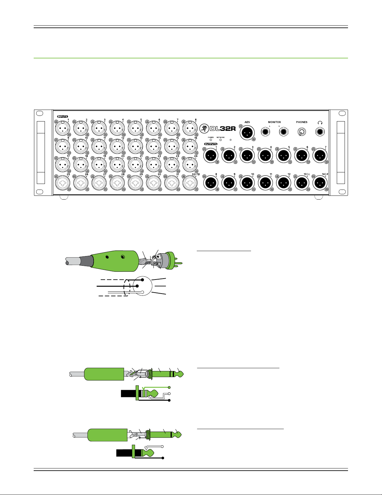
Each DL32R mixer is outtted with 24 XLR input jacks, 8 combo input jacks, 14 XLR output jacks, an XLR AES
output jack, 1/4" L/R monitor output jacks, one 1/4" phones output jack (and corresponding phones knob)
and power and network LEDs. Let’s take a look at each of these features, starting with the inputs.
DL32R Owner’s Manual
XLR and 1/4" Inputs
All channels may accept a balanced mic or line-level signal using an XLR connector.
They are wired as follows, according to standards specied by the AES (Audio Engineering Society).
In addition to accepting balanced mic or line-level signals using an XLR connector, channels 25-32
may also accept 1/4" line-level signals driven by balanced or unbalanced sources.
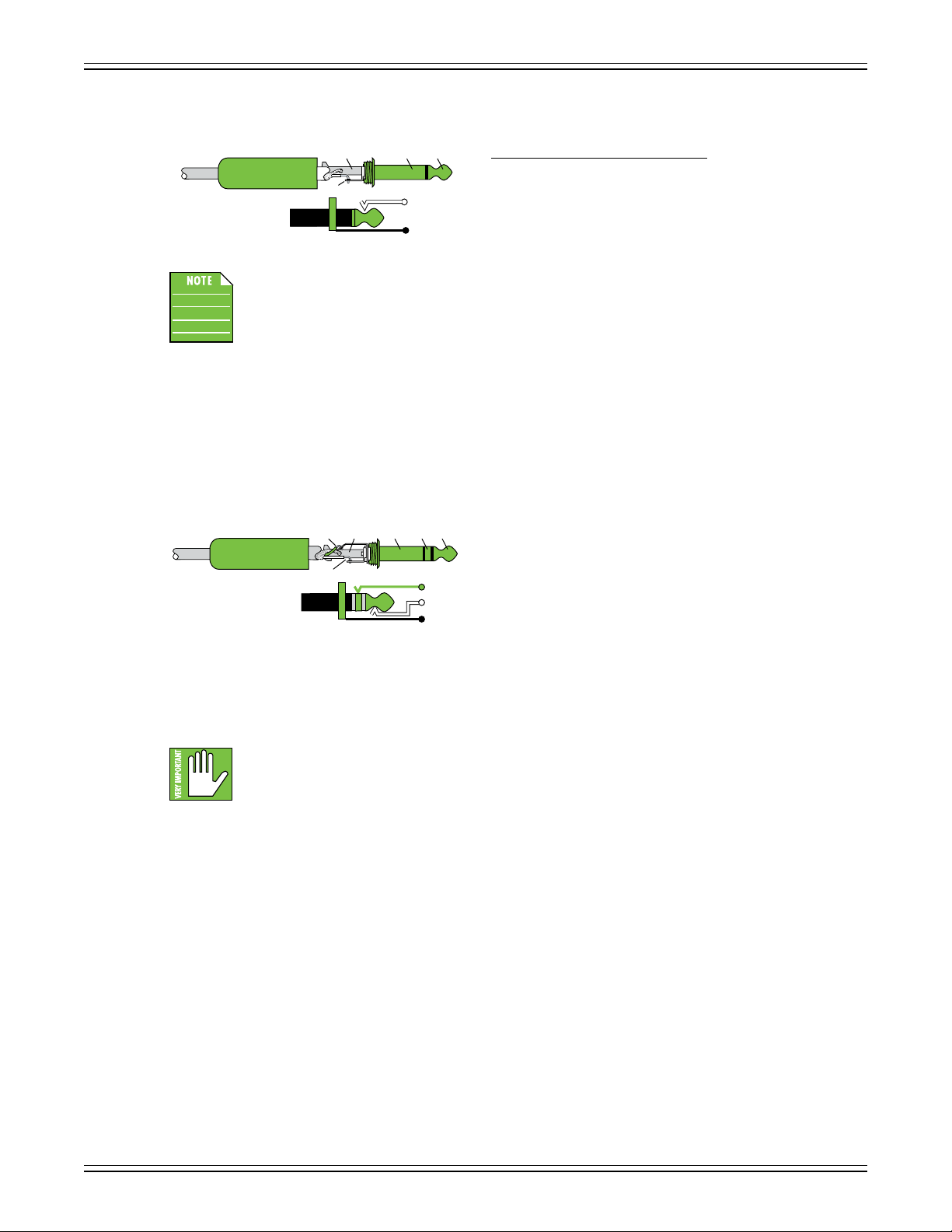
To connect balanced lines to these inputs, use a 1/4" Tip-Ring-Sleeve (TRS) plug. “TRS” stands for
Tip-Ring-Sleeve, the three connection points available on a stereo 1/4" or balanced phone jack or plug.
TRS jacks and plugs are used for balanced signals and stereo headphones and are wired as follows:
TIP
SHIELD
COLD
3
SLEEVERING
2
HOT
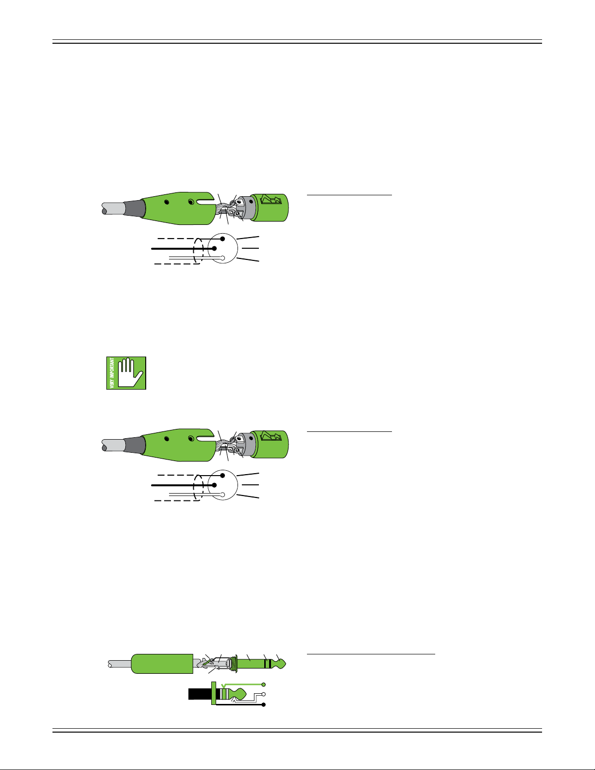
XLR Balanced Wiring:
Pin 1 = Shield (ground)
Pin 2 = Positive (+ or hot)
1
3
1
2
SHIELD
COLD
HOT
RING
TIPSLEEVE
Pin 3 = Negative (– or cold)
1/4" TRS Balanced Mono Wiring:
Sleeve = Shield
Tip = Hot (+)
RING
TIP
SLEEVE
Ring = Cold (–)
To connect unbalanced lines to these inputs, use a 1/4" mono (TS) phone plug, wired as follows:
1/4" TS Unbalanced Mono Wiring:
Sleeve = Shield
Tip = Hot (+)
5
TIP
SLEEVE
TIPSLEEVE
TIP
DL32R Owner’s Manual
XLR Outputs
These 14 male XLR connectors provide balanced line-level signals that represent the end of the mixer,
where the signals enter the real world. Connect these to line-level inputs of your main PA system, stage
monitors, external eects devices, headphone ampliers, and/or whatever else you desire. The PA/monitor
speaker system could either be passive (powered by external ampliers) and/or powered (with built-in power
ampliers). You may run separate mixes since all outputs are independent of each other and are completely
routable via the Master Fader control software. Pretty cool, huh?!
They are wired as follows, according to standards specied by the AES (Audio Engineering Society):
AES Output
SHIELD
1
XLR Balanced Wiring:
Pin 1 = Shield (ground)
COLD
3
HOT
1
2
3
2
SHIELD
COLD
HOT
Pin 2 = Positive (+ or hot)
Pin 3 = Negative (– or cold)
This male XLR-style connector provides professional, balanced stereo digital output from the DL32R.
Connect this output to the AES digital inputs of an amplier, system processor, audio distribution
system or recording devices. Like the analog outputs, you may select the signals to send to the AES
output via the Master Fader control software.
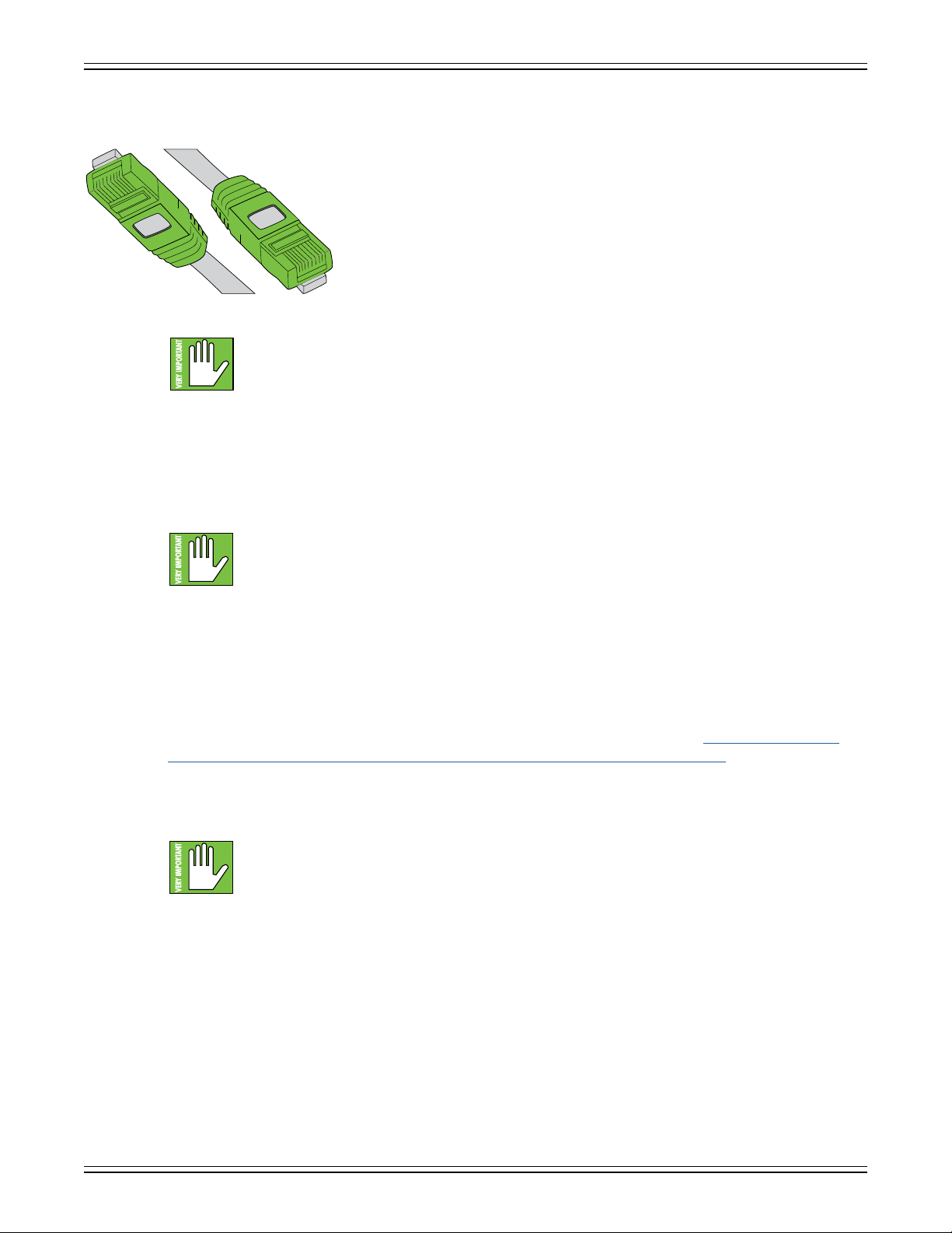
Resist the temptation to use a standard audio-grade XLR cable. AES digital audio data
is transmitted at far higher frequencies and require a special cable.
It is wired as follows, according to standards specied by the AES (Audio Engineering Society):
SHIELD
1
AES Balanced Wiring:
Pin 1 = Shield (ground)
COLD
3
HOT
1
2
3
2
SHIELD
COLD
HOT
Pin 2 = Positive (+ or hot)
Pin 3 = Negative (– or cold)
1/4" Monitor L/R Outputs
These 1/4" connectors allow you to send balanced or unbalanced line-level outputs to a wireless in-ear
monitor system or a pair of studio monitors. These could either be passive studio monitors powered
by an external amplier, or powered studio monitors with built-in power ampliers. If monitor outputs
are not needed, these connectors may be changed to output any signals on the mixer via the Master
Fader control software.
To connect balanced lines to these inputs, use a 1/4" Tip-Ring-Sleeve (TRS) plug. “TRS” stands for
Tip-Ring-Sleeve, the three connection points available on a stereo 1/4" or balanced phone jack or plug.
TRS jacks and plugs are used for balanced signals and stereo headphones and are wired as follows:
TIPSLEEVE
SLEEVERING
RING
1/4" TRS Balanced Mono Wiring:
Sleeve = Shield
TIP
RING
TIP
SLEEVE
Tip = Hot (+)
Ring = Cold (–)
6
DL32R Owner’s Manual
SLEEVE
To connect unbalanced lines to these inputs, use a 1/4" mono (TS) phone plug, wired as follows:
Phones Output Jack
This 1/4" TRS connector supplies the output to stereo headphones. The volume is controlled with the
phones knob located to the left of the output jack. The signals sent to this jack are the same as the signals
sent to the monitor outputs, described on the previous page.
The phones output follows standard conventions:
SLEEVE
TIPSLEEVE
1/4" TS Unbalanced Mono Wiring:
Sleeve = Shield
TIP
TIP
Tip = Hot (+)
Unbalanced cables can be noisy. If the studio monitors support balanced cables,
we highly recommend using those instead of unbalanced cables.
TIPSLEEVE
SLEEVERING
RING
Tip = Left channel
Ring = Right channel
TIP
RING
TIP
SLEEVE
Sleeve = Ground
Phones Knob
This knob is used to adjust the volume from the phones output jack, from o to maximum gain (max).
The phones knob is an analog control, and is therefore NOT recallable.
a channel or doing anything new that may aect the headphone volume. Then turn it up slowly as
you listen carefully.
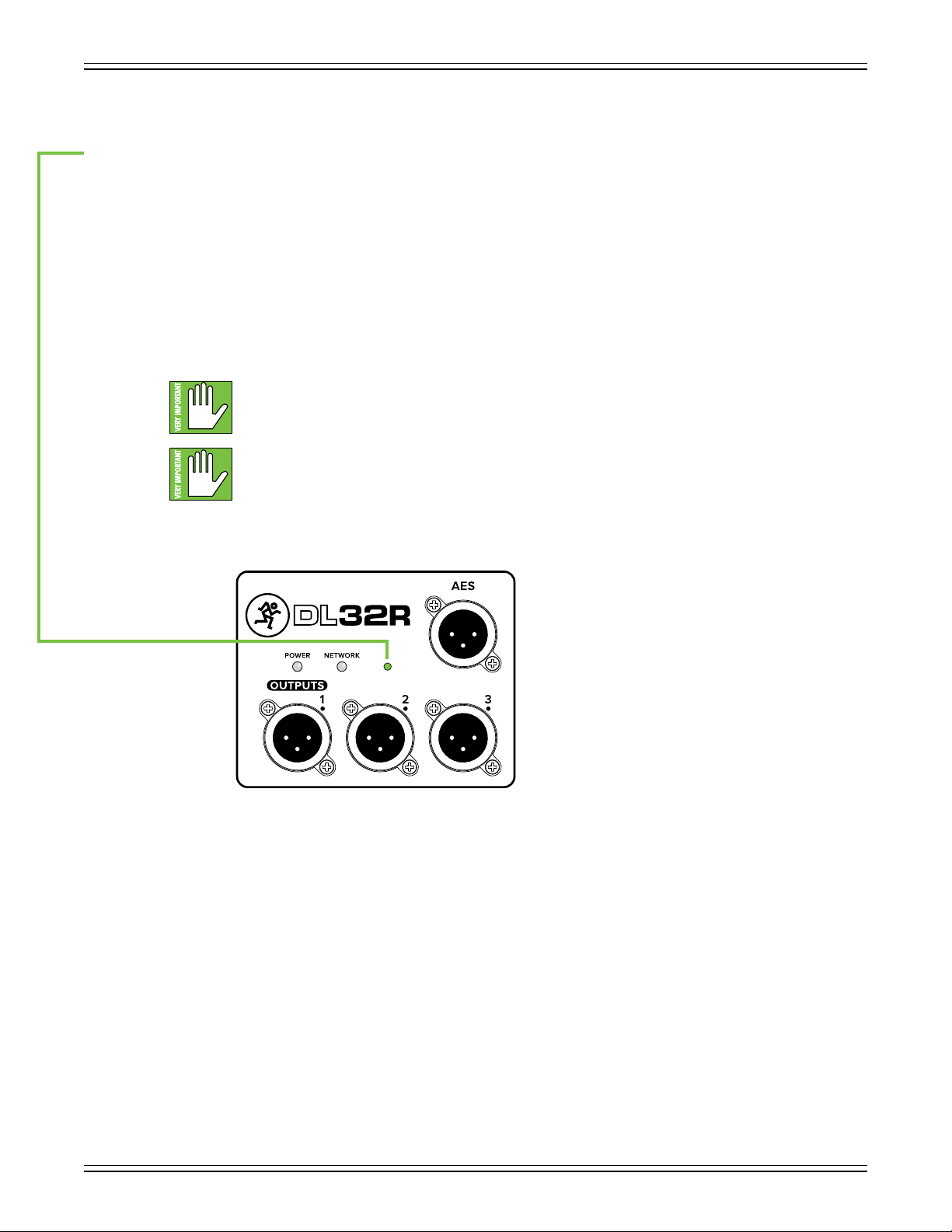
Power LED
For the most part, this dual-colored LED will illuminate solid green when the DL32R is powered on
and funtioning normally. However, this LED could also illuminate red, and it has several other identiers,
as well. Please refer to the table in Appendix C for all possibilities.
Network LED
For the most part, this dual-colored LED will illuminate solid green when the basic card is functioning
normally and an iPad connection is established
has several other identiers, as well. Please refer to the table in Appendix C for all possibilities.
Warning: The headphone amp is loud and could cause permanent hearing damage.
Even intermediate levels may be painfully loud with some headphones. BE CAREFUL!
Always turn the phones knob all the way down before connecting headphones, soloing
. However, this LED could also illuminate red, and it
7
DL32R Owner’s Manual
Force Update Button
The force update button is conveniently located right next to the power and network LEDs and just below
the awesome DL32R logo. In a perfect world, this button would just sit there without a care in the world,
umbrella drink in hand, beach, surf and sun on a daily basis. In all likelihood, this button will live his / her
dream out, while the rest of us can only dream of such a life.
The DL32R and Master Fader app do a great job at letting you know when either (or both) the software
and rmware need updating, but this button here forces a complete rmware update if the need ever arrives.
Here’s how to force a rmware update: rst, turn the mixer o. Now, with a bent paperclip, poke the force
update button, then power up the mixer with the button depressed. The mixer will boot and you will be
prompted with an update bubble the next time an iPad with the Master Fader app is turned on.
Now that you know how to force an update, here’s a friendly reminder that you should let
the button remain peaceful, calm and tranquil, only forcing a rmware update if instructed
by Tech Support. Thank you for listening!
Save any current show to your iPad before forcing an update or you may lose it.
The show and your sanity!
8
Chapter 3 : DL32R Rear Panel
Introduction
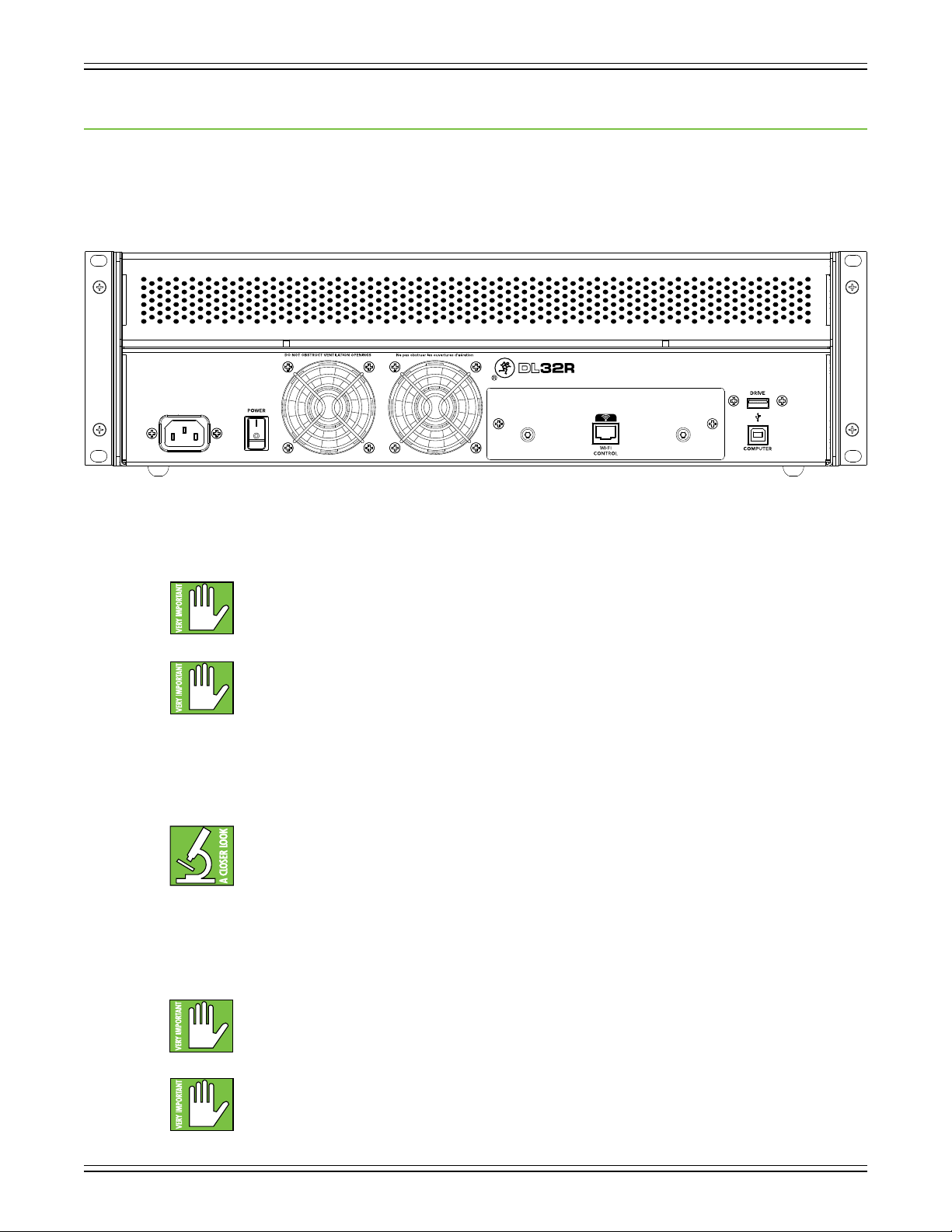
The rear panel of each DL32R is outtted with a power connector, a power switch, two fan vents,
a removable expansion slot, an Ethernet connector and two USB slots to stream multichannel audio
to and from (one for a hard drive, one for a computer)
DL32R Owner’s Manual
.
Power Connector
This is a standard 3-prong IEC power connector. Connect the detachable power cord (included in
the packaging) to the power receptacle, and plug the other end of the power cord into an AC outlet.
Power Switch
Press the top of this rocker switch in to turn the DL32R on and
the mixer o.
Fan Vents
The DL32R is cooled with two fans on the rear of the unit. Air is drawn in through the sides and sloping
part of the top panel, and is expelled through the rear fan openings. The speed of these fans is adjusted
automatically based on the temperature of the unit and its surroundings.
Make sure that the AC power is matched to the AC power indicated on the rear panel
(below the IEC receptacle).
Warning: Disconnecting the plug’s ground pin is dangerous. Don’t do it!
In fact, it’s a bad idea to remove anything from – or add anything to, for that matter – the line
cord. Again, don’t do it!
press the bottom of this switch to turn
As a general guide, the DL32R should be turned on rst, before any external power ampliers
or powered speakers. As such, it should also be turned o last. This will reduce the possibility
of any turn-on or turn-o thumps in the PA.
Always maintain at least four inches clearance behind, and one inch clearance on each side of
the unit.
When installing into a rack, the rear should be open with at least four inches of clearance behind
the rack and adjacent structures (maintaining the one inch clearance on each side of the unit
within the rack). For racks with only front ventilation, leave at least one rack space open above
and below the unit (maintaining the one inch side and four inch rear clearances around the unit
within the rack).
9
DL32R Owner’s Manual
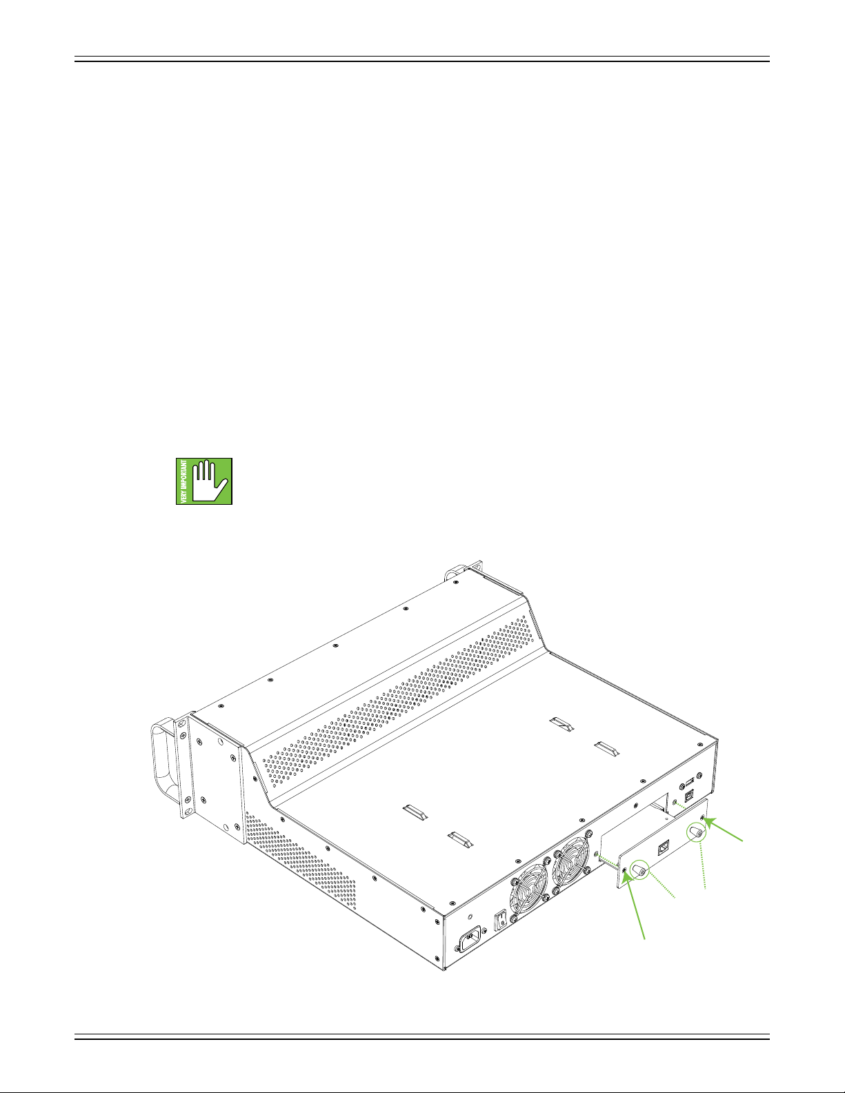
Removable Expansion Slot
This slot accepts expansion cards for audio networking, recording and other control options.
Each card contains pull tabs for easy installation and removal of cards, as well as two Phillips head
screws to hand-tighten the card to the mixer. The DL32R comes with a standard network card already
installed. As seen in the illustration below, this card contains a single network port for control.
Here’s how to remove a card from the mixer’s expansion slot:
(1) — Using a Phillips screwdriver, unscrew and remove the two screws keeping the card secured
to the mixer. Keep the screws in a safe place; you’re going to re-use them!
(2) — Using your index nger and thumb of each hand, grab the card’s two pull tabs and gently
remove the card straight out from the mixer.
(3) — Place the card in an antistatic bag – one is included with the new card – and keep it in a safe
place; you might re-use it some day.
Adding a card to the mixer is basically the same steps as above, but in reverse:
(1) — Remove the card from the antistatic bag and admire its beauty.
(2) — Using your index nger and thumb of each hand, grab the card’s two pull tabs and gently
slide the card straight into the mixer.
Make sure to line up the card with the side rails before sliding the card in.
There are notches located at the bottom on each side of the expansion slot
to help line up and easily guide the card.
(3) — Using a Phillips screwdriver, hand-tighten the two screws (that you kept in a safe place!),
to keep the card secured to the mixer.
Screw
10
Pull tabs
Screw
Network Connector
USB A – Drive
The DL32R’s USB type A connector allows 32 channel (48 kHz, 24-bit) recording and playback to (and from)
a USB hard drive.
DL32R Owner’s Manual
As stated previously, the DL32R arrives equipped with an expansion card that
contains a single network port for control. The purpose in life of this 100 Mb
network connector is to connect the mixer to a Wi-Fi router via CAT5 Ethernet
cable, thus enabling wireless control.
Plug one end of the CAT5 Ethernet cable into the mixer’s network connector
and the other end of the CAT5 Ethernet cable into a LAN port on the router,
NOT a WAN port. Most routers allow the use of either a straight-wired cable
or crossover cable, but If you have a choice, a straight-wired CAT5 Ethernet
cable is the way to go to ensure smooth operation with any router.
Complete directions for setting up the router may be found in the Master Fader Reference
Guide.
Any combination of channels or outputs may be selected as the record source and playback destination.
USB B – Computer
The DL32R’s USB type B connector allows 32x32 channels of recording and playback to a connected
computer over USB 2.0 by presenting the DL32R as an audio class 2.0 compliant device. What this means
is that connecting it to a Mac should work automatically with no additional drivers. Windows drivers will
require separate installation, but this is included. Simply download it from our website!
Additionally, you may stream audio directly to and from an iPad using the iPad camera connection kit.
Any combination of channels or outputs may be selected as the record source and playback destination.
USB A and USB B connectors may NOT be used simultaneously. If a hard drive is connected to
USB A, it will take priority over anything connected to USB B. For example, if you are recording
to a DAW (via computer connected to the USB B port) and connect a hard drive to the USB A
port, the hard drive will mount and the DAW recording interrupted. Additionally, the DL32R
will no longer show up as an available device until the USB A connection is removed and the
USB B connection is disconnected and reconnected again.
11
 Loading...