

Page 1
Mack
E L E C T R O N I C
®
V-MAC
VEHICLE MANAGEMENT
AND CONTROL WITH
CO-PILOT DISPLAY
®
IV
®
V-MAC
®
IV
E L E C T R O N I C
®
V-MAC
VEHICLE MANAGEMENT
AND CONTROL WITH
CO-PILOT DISPLAY
®
IV
21968603
© Mack Trucks, 2013
21968603
21968603
January 2013
Page 2

Page 3

Foreword
Thismanualcontainsinformationconcerningtheoperationandfunction
oftheElectronicV ehicleManagementandControl(V-MAC)IVV ehicle
ManagementandControlwithCo-PilotDisplay.Theinformationinthis
manualappliestovehiclesbuiltJanuary2013andlater .Pleasekeepthis
manualinthevehicleatalltimes.
Note:Illustrationsinthismanualareusedforreferenceonlyandmay
differslightlyfromtheactualvehicle.However,keycomponents
addressedinthisdocumentarerepresentedasaccuratelyaspossible.
MackTrucks
Wacol,QLD,Australia
Ordernumber:PV776-21968603
©2013MackTrucks Wacol,QLD,Australia
Allrightsreserved.Nopartofthispublicationmaybereproduced,stored
inretrievalsystem,ortransmittedinanyformsbyanymeans,electronic,
mechanical,photocopying,recordingorotherwise,withouttheprior
writtenpermissionofMackTrucks.
Page 4

Page 5

Contents
Introduction..............................................................................................................................1
SAFETYINFORMA TION....................................................................................................2
ServiceProceduresandToolUsage...................................................................................3
V-MACCo-PilotOperator'sManual.....................................................................................7
SYSTEMOVERVIEW..........................................................................................................7
SystemSummary...............................................................................................................7
SYSTEMCOMPONENTS....................................................................................................9
VehicleElectronicControlUnit(VECU)..........................................................................9
EngineControlModule(ECM).........................................................................................11
INDICA
EXHAUSTAFTERTREA TMENTSYSTEM.......................................................................23
AftertreatmentDPFRegenerationandPTOOperation(CumminsISX)..............................32
STARTINGTHEVEHICLE.................................................................................................32
CRUISEANDENGINESPEEDCONTROL.......................................................................33
ACCESSORYRELA YCONTROL......................................................................................41
PROGRAMMABLEFEA TURES.........................................................................................42
ELECTRICALACCESSORYCONNECTIONPOINTS.....................................................48
TORS,LIGHTSANDDASHBOARDSWITCHES...............................................15
CabandDashboardSwitches.............................................................................................15
ElectronicMalfunctionIndicator.......................................................................................16
HighExhaustSystemTemperature(HEST)Indicator.......................................................17
ShutdownWarningIndicator.............................................................................................18
EngineDerate(ForMackEnginesOnly)..........................................................................19
AftertreatmentDPFSmartSwitch(IfEquipped)..............................................................21
AftertreatmentDPFRegeneration,CumminsISX............................................................23
AftertreatmentDPFPassiveRegeneration,CumminsISX...............................................24
AftertreatmentDPFParkedRegeneration,CumminsISX................................................25
AftertreatmentDPFInhibit/StopRegeneration.................................................................26
CruiseControl....................................................................................................................33
EngineSpeedControl........................................................................................................38
EngineBrake......................................................................................................................41
Cruise'NBrakeEngagementDelay..................................................................................44
EngineHighIdleSpeedifStopped....................................................................................44
EngineHighIdleSpeedinUpperGears............................................................................44
LowIdleAdjustment.........................................................................................................44
SmartIdleElevatedIdleRPMTime..................................................................................46
IdleShutdown....................................................................................................................46
SpeedSensorTamperDetection........................................................................................47
BatteryPost(BA TT)..........................................................................................................48
IgnitionPost(IGN)............................................................................................................48
GroundPost(GND)...........................................................................................................48
RPMOutput.......................................................................................................................48
Km/hOutput......................................................................................................................49
SAE/ATAJ-1708Posts(SeriesLinkAandB)..................................................................49
CBRadioPowerJack(CBRadio+)(LocatedonDashboard)..........................................49
CBRadioGroundJack(CBRadio−)(LocatedonDashboard)........................................49
Page 6

INSTRUMENTCLUSTERDISPLAY.................................................................................50
DashClusterSet-UpProgramming...................................................................................50
InstrumentClusterComponents........................................................................................51
DriverInformationDisplay................................................................................................53
DiagnosticTroubleCodes(DTCs)........................................................................................54
ElectronicDashDisplay....................................................................................................54
CO-PILOT®DISPLAY.........................................................................................................58
IntroductionandPurpose...................................................................................................58
CO-PILOTSYSTEMOVERVIEW......................................................................................59
Set-UpProgramming.........................................................................................................59
CO-PILOT®OPERA TIONS.................................................................................................63
UsingtheCo-Pilot®..........................................................................................................63
CO-PILOTSYSTEMOVERVIEW......................................................................................64
ESCButton........................................................................................................................64
Enter(↵)Button...............................................................................................................64
Up&DownButtons..........................................................................................................64
CO-PILOT®LAYOUT.........................................................................................................65
ScreenTypes......................................................................................................................65
Driver'sIDScreens............................................................................................................66
ChangeDriverID...............................................................................................................70
CO-PILOT®STARTUPSCREENS....................................................................................72
MACKLogoIntro.............................................................................................................72
CurrentConditions.............................................................................................................73
CO-PILOT®MENUSCREENS...........................................................................................74
MainMenu—StationaryV ehicle.....................................................................................74
MainMenu—MovingV ehicle.........................................................................................75
CO-PILOT®ANYTIMESCREENS....................................................................................77
FuelEconomy....................................................................................................................77
TripInformation.................................................................................................................78
Gauges................................................................................................................................80
BlackPanel........................................................................................................................81
CO-PILOT®STATIONARYSCREENS..............................................................................82
Diagnostics.........................................................................................................................83
Maintenance.......................................................................................................................84
DELMessages...................................................................................................................85
SetUp.................................................................................................................................86
CO-PILOT®INTERRUPTSCREENS.................................................................................87
IdleShutdownWarning.....................................................................................................87
DriverOverspeedWarning(ifA vailable)..........................................................................87
WarningSevereEngineOverspeed....................................................................................88
EngineBrakeOverspeedWarning.....................................................................................89
SevereEngine&EngineBrakeOverspeedWarning.........................................................90
MaintenanceReminder(forFutureSupport).....................................................................90
LowV oltageDisconnectActive........................................................................................91
InterWheelLock...............................................................................................................91
Page 7

SmartIdleActive...............................................................................................................92
StarterInhibit.....................................................................................................................92
DriverTripReset...............................................................................................................93
TripAdvanced....................................................................................................................94
IdleCooldownActivated...................................................................................................94
Page 8

Page 9

WARNING
Theinformationinthismanualisnotall
inclusiveandcannottakeintoaccount
alluniquesituations.Notethatsome
illustrationsaretypicalandmaynotreect
theexactarrangementofeverycomponent
installedonaspecicchassis.
Theinformation,specications,and
illustrationsinthispublicationarebased
oninformationthatwascurrentatthetime
ofpublicationspartofthispublicationmay
bereproduced,storedinaretrievalsystem,
orbetransmittedinanyformbyanymeans
including(butnotlimitedto)electronic,
mechanical,photocopying,recording,or
otherwisewithoutpriorwrittenpermission
ofMACKTrucks.
Introduction1
Page 10
2Introduction
SAFETYINFORMA TION
IMPORTANT:Beforedrivingthisvehicle,becertainthatyouhavereadandthatyou
fullyunderstandeachandeverystepofthedrivingandhandlinginformationinthis
manual.Becertainthatyoufullyunderstandandfollowallsafetywarnings.
ITISIMPORTANTTHA TTHEFOLLOWINGINFORMA TIONBEREAD,
UNDERSTOODANDAL WAYSFOLLOWED.
Cautionarysignalwords(Danger-Warning-Caution)mayappearinvariouslocations
throughoutthismanual.Informationaccentedbyoneofthesesignalwordsmustbeobserved
tominimizetheriskofpersonalinjurytoservicepersonnel,orthepossibilityofimproper
servicemethodswhichmaydamagethevehicleorcauseittobeunsafe.
Notesareusedtoemphasizeareasofproceduralimportanceandprovidesuggestionsfor
easeofrepair.Thefollowingdenitionsindicatetheuseoftheseadvisorylabelsasthey
appearthroughoutthemanual:
DANGER
Dangerindicatesanunsafepracticethat
couldresultinseriouspersonalinjuryor
death.Adangeradvisorybannerisin
whitetypeonablackbackgroundwitha
blackborder.
WARNING
Warningindicatesanunsafepracticethat
couldresultinpersonalinjury.Awarning
advisorybannerisinblacktypeonagray
backgroundwithablackborder.
CAUTION
Cautionindicatesanunsafepracticethat
couldresultindamagetotheproduct.A
cautionadvisoryisinblacktypeona
whitebackgroundwithablackborder.
Note:Noteindicatesaprocedure,practice,
orconditionthatmustbefollowedinorder
forthevehicleorcomponenttofunctionin
themannerintended.
Page 11

Introduction3
ServiceProceduresandToolUsage
Anyoneusingaserviceprocedureortoolnotrecommendedinthismanualmustrst
satisfyhimselfthoroughlythatneitherhissafetynorvehiclesafetywillbejeopardizedby
theservicemethodheselects.Individualsdeviatinginanymannerfromtheinstructions
providedassumeallrisksofconsequentialpersonalinjuryordamagetoequipmentinvolved.
Alsonotethatparticularserviceproceduresmayrequiretheuseofaspecialtool(s)designed
foraspecicpurpose.Thesespecialtoolsmustbeusedinthemannerdescribed,whenever
speciedintheinstructions.
Page 12
4Introduction
DANGER
Beforestartingavehicle,alwaysbeseated
inthedriver'sseat,placethetransmission
inneutral,applytheparkingbrakes,
andpushintheclutchpedal.Failureto
followtheseinstructionscouldproduce
unexpectedvehiclemovement,whichcan
resultinseriouspersonalinjuryordeath.
DANGER
Beforeworkingonavehicle,placethe
transmissioninneutral,settheparking
brakes,andblockthewheels.Failureto
followtheseinstructionscouldproduce
unexpectedvehiclemovement,whichcan
resultinseriouspersonalinjuryordeath.
DANGER
Engine-drivencomponentssuchasPower
Take-Off(PTO)units,fansandfanbelts,
driveshaftsandotherrelatedrotating
assemblies,canbeverydangerous.Do
notworkonorserviceengine-driven
componentsunlesstheengineisshut
down.Alwayskeepbodypartsandloose
clothingoutofrangeofthesepowerful
componentstopreventseriouspersonal
injury.BeawareofPTOengagementor
nonengagementstatus.Alwaysdisengage
thePTOwhennotinuse.
WARNING
Whenworkingonavehiclebyusing
wirelesscommunicationunits,itisnot
alwaysapparenttoothersthatwork
isinprogressonthevehicle.Certain
activities,suchasactivationofcertain
vehiclecomponentsorsystems,cancause
injurytopersonsclosetothevehiclewho
areunawareoftheongoingactivities.
Alwayskeepaconnectedvehicleunder
closeobservationwhenusingwireless
communicationunitsandinformother
personsinthevicinityofthevehicleabout
theongoingactivities.
WARNING
Thetemperatureoftheexhaustsystem
componentsduringtheregeneration
processcanexceed500°C(1000°F).
Variousfactors(includingambientair
temperature(AA T)anddurationofthe
regenerationprocess)determinewhen
thesecomponentswillreturntonormal
operatingtemperatureafterregeneration
hascompleted.Beextremelycareful
aroundthesehotcomponents.Contact
withthesecomponentscanresultinserious
personalinjury.
DANGER
Donotworkunderavehiclethatis
supportedonlybyahydraulicjack.The
hydraulicjackcouldfailsuddenlyand
unexpectedly,resultinginseverepersonal
injuryordeath.Alwaysusejackstandsof
adequatecapacitytosupporttheweightof
thevehicle.
CAUTION
Beforetowingthevehicle,placethe
transmissioninneutralandlifttherear
wheelsofftheground,ordisconnect
thedrivelinetoavoiddamagetothe
transmissionduringtowing.
Page 13

Introduction5
CAUTION
Whenregenerationoccurs,thetemperature
oftheexhaustwillbeelevated.DONOT
parkthevehiclewiththeexhaustoutlet
underlowhangingoverheadammable
objectssuchastrees,awnings,etc.,that
couldbedamagedbyelevatedexhaust
temperatures.DONOTattemptto
regenerateinsideagarageorenclosedarea
ifthetailpipeisattachedtoanexhaust
ventilationsystemasthehosematerial
maynotberatedforthehightemperature.
CAUTION
Whentheinhibitpositionispressed,
theDPFswitchwillremaininalocked
position.Itisimportant,therefore,to
immediatelysettheswitchbacktothe
neutralpositionwhensafetodoso.Failure
tosettheswitchbacktotheneutralposition
mayresultinanenginederate,cloggedor
damagedDPF .
REMEMBER,
CAUTION
Failuretoperformaregenerationina
timelymannermayresultinenginederate,
cloggedAftertreatmentDieselParticulate
Filter(DPF)ordamagetothelter.
SAFETY...ISNOACCIDENT!
Page 14

6Introduction
Everypossibleoccurrencethatmayinvolveapotentialhazardcannotbeanticipated.
Accidentscanbeavoidedbyrecognizingpotentiallyhazardoussituationsandtaking
necessaryprecautions.Performingserviceprocedurescorrectlyiscriticaltotechnician
safetyandsafe,reliablevehicleoperation.
Thefollowinglistofgeneralshopsafetypracticescanhelptechniciansavoidpotentially
hazardoussituationsandreducetheriskofpersonalinjury .DONOTperformanyservices,
maintenanceproceduresorlubricationsuntilthismanualhasbeenreadandunderstood.
•Performallserviceworkonaat,levelsurface.Blockwheelstopreventvehiclefrom
rolling.
•DONOTwearloose-ttingortornclothing.Removeanyjewelrybeforeservicing
vehicle.
•ALWA YSwearsafetyglassesandprotectiveshoes.Avoidinjurybybeingawareof
sharpcornersandjaggededges.
•Usehoistsorjackstoliftormoveheavyobjects.
•NEVERrunengineindoorsunlessexhaustfumesareadequatelyventedtotheoutside.
•Beawareofhotsurfaces.Allowenginetocoolsufcientlybeforeperforminganyservice
ortestsinthevicinityoftheengine.
•Keepworkareacleanandorderly.Cleanupanyspilledoil,grease,fuel,hydraulic
uid,etc.
•Onlyusetoolsthatareingoodcondition,andalwaysuseaccuratelycalibratedtorque
wrenchestotightenallfastenerstospeciedtorques.Ininstanceswhereprocedures
requiretheuseofspecialtoolswhicharedesignedforaspecicpurpose,useonlyin
themannerdescribedintheinstructions.
•Donotstorenaturalgaspoweredvehiclesindoorsforanextendedperiodoftime
(overnight)withoutrstremovingthefuel.
•Neversmokearoundanaturalgaspoweredvehicle.
Page 15

V-MACCo-PilotOperator'sManual7
SYSTEMOVERVIEW
SystemSummary
TheV ehicleManagementandControl(V-MAC)IVSystemisanelectronicenginecontrol
systemconsistingofthefollowingmajorcomponents:
•EngineControlModule(ECM)
•InstrumentCluster
•VehicleElectronicControlUnit(VECU)
ToenableV ehicleManagementandControl(V-MAC)IVtoperformitsenginemanagement
andcontrolfunctions,thefollowingsensors(ifavailableandtted)provideinformation
tothesystem.
•AirBrakeApplicationSensor
•AirSuspensionSensor
•Air-HumiditySensor
•AmbientAirTemperature(AA T)Sensor
•IntakeManifoldPressure(IMP)Sensor
•IntakeManifoldAirTemperatureSensor
•CamshaftPosition(CMP)Sensor
•EngineCoolantLevel(ECL)Sensor
•EngineCoolantTemperature(ECT)Sensor
•CrankshaftPosition(CKP)Sensor
•CrankcasePressure(CCP)Sensor
•EngineExhaustGasRecirculation(EGR)DifferentialPressureSensor
•FrontDriveAxleT emperatureSensor
•FuelPressureSensor
•EngineOilLevel(EOL)Sensor
•EngineOilTemperature(EOT)Sensor
•EngineOilPressure(EOP)
•PrimaryandSecondaryAirPressureSensor
•RearDriveAxleT emperatureSensor
•AcceleratorPedalPosition(APP)Sensor
•TransmissionOilT emperatureSensor
•EngineTurbochargerSpeedSensor
•VehicleSpeed(RoadSpeed)Sensor
•WaterinFuelFilterSensor
Page 16

8V-MACCo-PilotOperator'sManual
Thefollowingswitchesandfunctionsarealsomonitoredtoprovideinformationrelatedto
driveractions.
•A/CPressureSwitch(Optional)
•ClutchPedalPosition(CPP)Switch
•EngineBrakeLowandHighSwitch(Optional)
•Ignitionkey
•PowerT akeoff(PTO)Switches(Optional)
•ServiceBrakeandParkingBrakeSwitches
•Set/ResumeSwitch
•SpeedControlOn/OffSwitch
•StarterEngagedSwitchInput(Optional)
•TorqueLimitingSwitch(Optional)
Thismanualprovidesacompletedescriptionofthesystemcomponents,theirfunctionsand
locationsonthevehicle.
Page 17

V-MACCo-PilotOperator'sManual9
SYSTEMCOMPONENTS
VehicleElectronicControlUnit(VECU)
TheVECUismountedunderneathpanelDasshowninthegraphic'sbelow.
TheVECUisanelectroniccontrolmodulewhichprovidesawidevarietyoffunctions
including:
•CruiseControl
•DiagnosticTroubleCode(DTC)Logging
•DifferentialLocking
•IdleShutdown
•MaintenanceInformation
•RoadSpeedLimiting
•SpeedControl
W3060890
VECULocation
Page 18

10V-MACCo-PilotOperator'sManual
VECU
W3060892
Page 19

V-MACCo-PilotOperator'sManual11
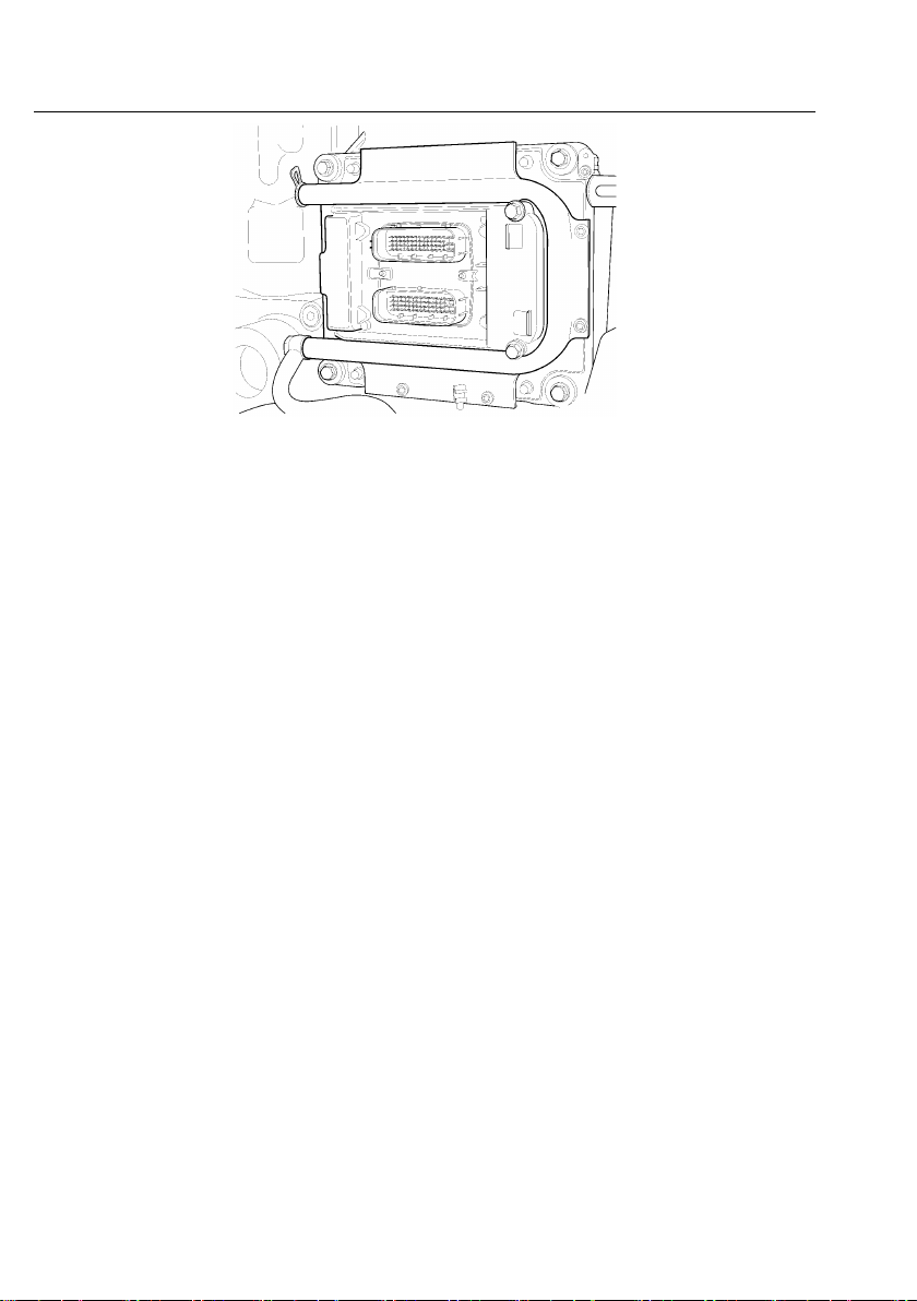
EngineControlModule(ECM)
TheECMisanelectroniccontrolunit(ECU)locatedtotheleftsideoftheengineandis
mountedtothefuelcooler,whichismountedbeneaththeinletmanifold.TheECMprovides
thefollowinginformationandfunctions:
•IntakeManifoldPressure(IMP)
•EngineCoolantLevel(ECL)
•EngineCoolantTemperature(ECT)
•CustomerRoadSpeedLimiting
•DiagnosticTroubleCode(DTC)Logging
•EngineOilPressure(EOP)
•EngineOilTemperature(EOT)
•EngineProtection
•EngineShutdown
•EngineSpeed(RPM)Control(basedoncommandsfromV ehicleElectronicControl
Unit(VECU)
•ExhaustAftertreatmentSystem
•FanControl
•FuelControl
•FuelTemperature
•TimingControl
•VehicleLimitingSpeeds
EngineControlModule(ECM)Location
C0035356
Page 20
12V-MACCo-PilotOperator'sManual
EngineControlModule(ECM)(MACKMP7)
C0035360
Page 21

V-MACCo-PilotOperator'sManual13
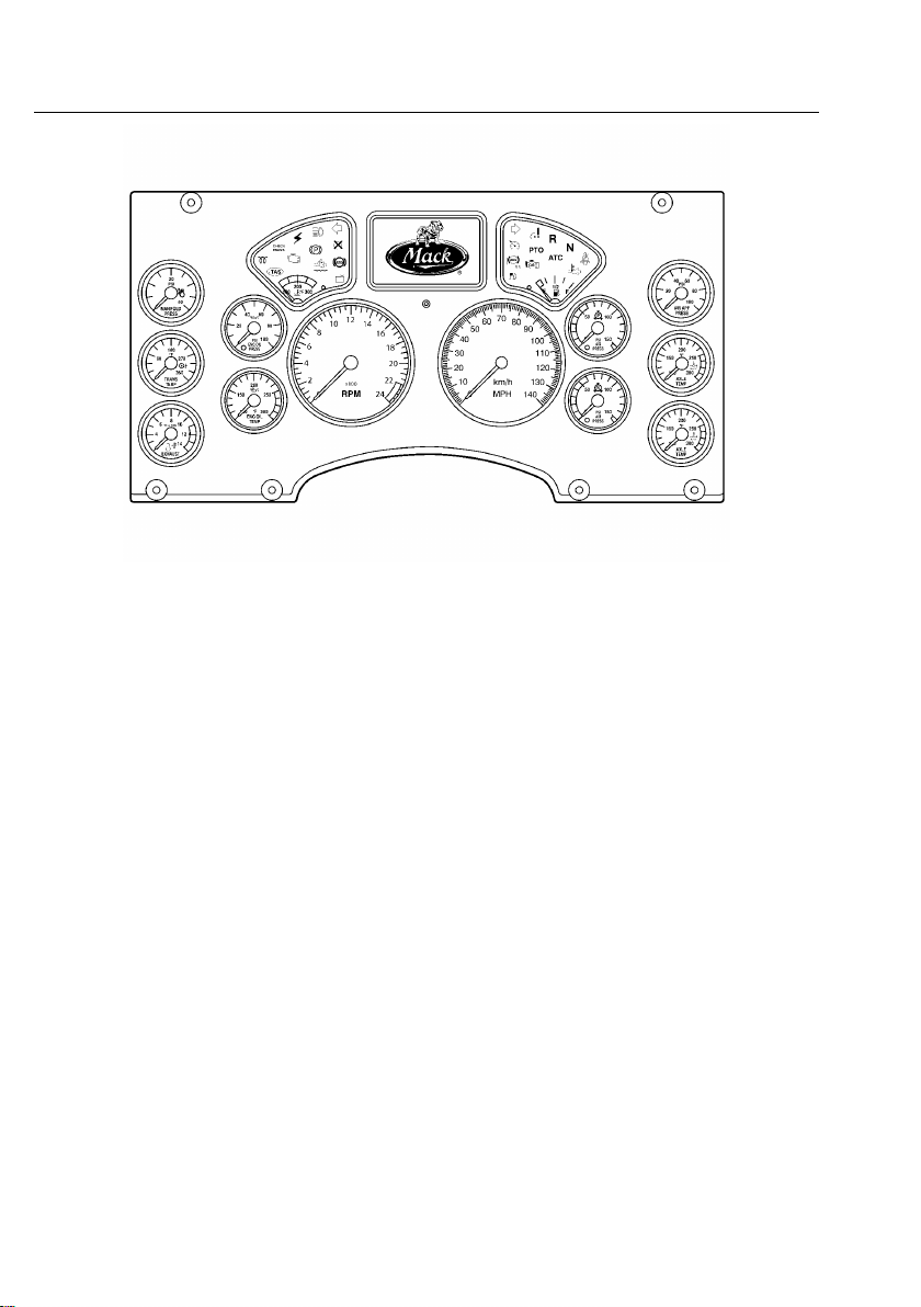
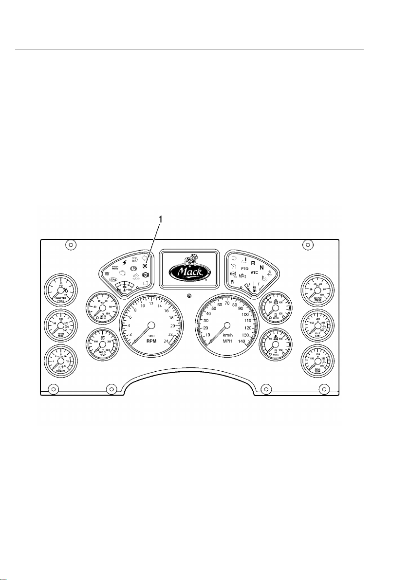
InstrumentCluster
TheV ehicleManagementandControl(V-MAC)IVInstrumentClusterisaone-piece
unitcomposedofgaugesandaninformationdisplay.TheInstrumentClusterreceives
informationfromtheVECUandEECUandthensendsinformationbacktotheVECUand
EECU.Informationisdisplayedwhenrequiredorrequestedviaastalkswitch(Co-Pilot®
only).
TheInstrumentClusterprovidesthefollowinginformation:
•AirBrakeApplication(Optional)
•AirSuspensionPressure
•AxleOilTemperature(Optional)
•CoolantTemperature(viaECM)
•EngineandV ehicleSpeedDisplay
•ExhaustTemperature(Optional)
•FuelLevel
•HighBeamStatus
•HighExhaustSystemTemperature(HEST)
•OutsideTemperature
•OilPressure(viaECM)
•PrimaryandSecondaryAirPressure
•SpeedometerandTachometerOutputs
•TransmissionOilT emperature(Optional)
•VehicleDistance
Page 22
14V-MACCo-PilotOperator'sManual
InstrumentClusterModule
Note:Theinstrumentclustermoduleshownismeantasanexampleonly .Thedisplay
featuresvarydependingontheemissionoptionsforthevehicle.
W3036315
Page 23
V-MACCo-PilotOperator'sManual15
INDICATORS,LIGHTSANDDASHBOARDSWITCHES
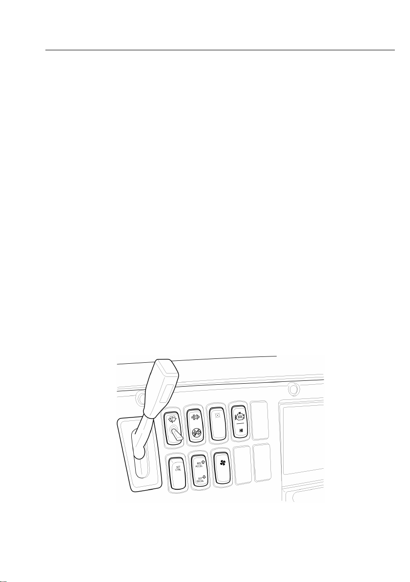
CabandDashboardSwitches
VariousfunctionsoftheV ehicleManagementandControl(V-MAC)IVsystemare
controlledbytheoperatorthroughswitcheslocatedonthedashboard.Thesefunctions
include:
•CruiseControl
•EngineBrakeOperation(Optional)
•EngineSpeed(RPM)Control
•ExhaustAftertreatmentSystem
•PTOOperation
Cruisecontrolandenginespeedcontrolfunctionsareexplainedinthismanualin“CRUISE
ANDENGINESPEEDCONTROL”,page33.
Inadditiontotheseoperator-selectableswitches,additionalswitchesprovideinformation
totheV ehicleElectronicControlUnit(VECU)throughnormaldrivingactivitiessuchas
applyingtheservicebrakes,parkingbrakesordisengagingtheclutch.Thelocationof
theseswitchesisasfollows:
•ClutchPedalPosition(CPP)switch
•Parkingbrakeswitch,locatedinlinewithintheparkingbrakecircuit
•Servicebrakeswitch,locatedinlinewithinthebrakesystem
CabandDashboardSwitches(Example)
W2076077
Page 24
16V-MACCo-PilotOperator'sManual
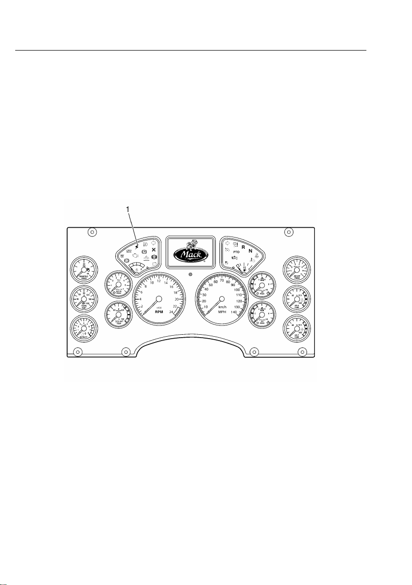
ElectronicMalfunctionIndicator
Theelectronicmalfunctionindicator,amberincolor,illuminatestoalertthedriverofan
electricalproblemwiththeV ehicleManagementandControl(V-MAC)IVsystem.The
V-MACIVsystemdoesaself-testwhentheignitionkeyisturnedtotheONposition.The
electronicmalfunctionindicatorstaysonwhilethistestisbeingperformed(approximately
sixseconds).Aftertheself-testiscompleted,theindicatorwillturnoffandremainoff
unlessaproblemisdetectedby(V-MAC)IV .Iftheindicatorturnsonwhilethevehicleis
beingdriven,(V-MAC)IVhasdetectedaproblem.Inmostcircumstances,thevehiclewill
operateeventhoughtheindicatorison;however,engineperformancemaybeaffected.
Foranexplanationoffaultcodeactivationandinterpretation,andacompletelistingofthese
codes,pleasereferto“DiagnosticTroubleCodes(DTCs)”,page54ofthismanual.
ElectronicMalfunctionIndicator
W3061049
Page 25
V-MACCo-PilotOperator'sManual17
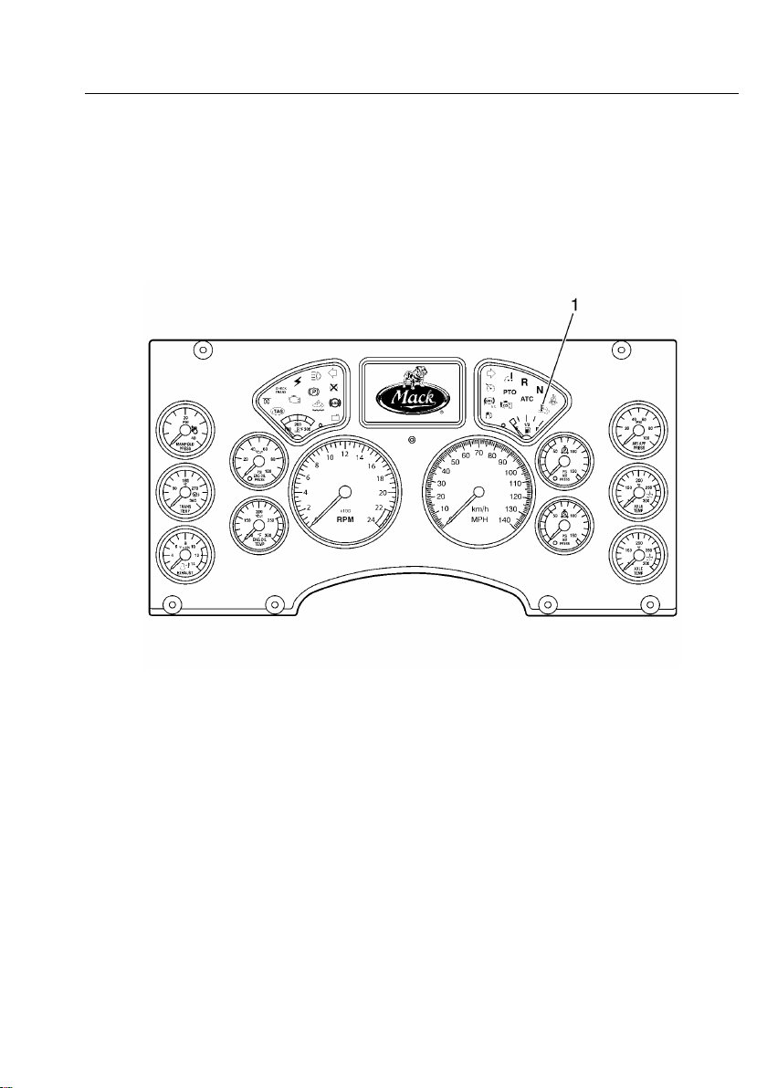
HighExhaustSystemTemperature(HEST)Indicator
TheHighExhaustSystemTemperature(HEST)indicator,amberincolor,illuminates
toalertthedriverwhenengineExhaustGasTemperatures(EGT)arehigh.TheHEST
indicatorwillalsoilluminateduringaaftertreatmentDieselParticulateFilter(DPF)parked
regenerationeventandwillturnoffaftertheregenerationiscompletedandtheEGThas
returnedtonormal.ForadditionalinformationabouttheHESTindicator,pleasereferto
“AftertreatmentDPFSmartSwitch(IfEquipped)”,page21.
HighExhaustSystemT emperature(HEST)Indicator
W3036496
Page 26
18V-MACCo-PilotOperator'sManual
ShutdownWarningIndicator
TheShutdownWarningindicator,redincolor,illuminatesiftheEngineCoolantLevel
(ECL)isbelowtheminimumlevelallowed,theEngineOilPressure(EOL)isbelow
theminimumallowed,theEngineCoolantTemperature(ECT)oraftertreatmentDiesel
ParticulateFilter(DPF)sootleveltriggerareabovethemaximumallowed.Somevehicles
alsohaveoptionalshutdownfunctionsavailablewhenthetransmissiontemperatureor
engineExhaustGasT emperatures(EGT)areabovemaximumallowablelimits.
Duringashutdownevent,V-MACIValsoprovidesanaudiblealarm.Thealarmwillalso
soundandtheredshutdownindicatorwillturnonwhenV-MACIVdetectsaproblemor
excessiveperiodsofidling.Shuttingtheenginedowniswarranted.
Theshutdownwarningindicatorisusuallylocatedontheleft-handsideonthedashcluster.
W3036501
EngineShutdownWarningIndicator(Red)
V-MACIVcanbeprogrammedtoactuallyshutdowntheengineifconditionswarrant(low
coolant,lowEOL,highEngineOilTemperature(EOT),highECT,highengineEGTor
highautomatictransmissionoiltemperatureifsoequipped).Shutdownismandatoryfor
CrankcasePressure(CCP).Withthisoptionenabled,theenginewillautomaticallyshut
downwithinapproximately30secondsaftertheredSHUTDOWNindicatorturnsonand
thealarmactivates(providedthevehicleisnotmovingabovetheroadspeedthreshold).
Page 27

V-MACCo-PilotOperator'sManual19
EngineDerate(ForMackEnginesOnly)
Forsomeconditions(seetablebelow),anenginederatecanoccurrstandifacondition
worsens,thenanengineshutdowncanoccur.
Note:ForCumminsengineinformationrefertotheCumminsengineoperatormanualor
aCumminsdealer
CONDITION
IntakeManifold
AirT emperature
Engine
Turbocharger
CompressorOutlet
Temperature
Engine
ExhaustGas
Recirculation
(EGR)
Temperature
Crankcase
Pressure(CCP)
HighEngine
Coolant
Temperature
(ECT)
ENGINEDERA TE
Deratestartsat120°C(248°F).
Fullderate(100%)occurswhen
temperatureisat140°C(284°F).
Deratestartsat245°C(473°F).
Torqueisderateddownto100%
at250°C(482°F).
Iftemperatureexceeds220°C
(428°F)formorethan20seconds
witha30secondperiod,derate
starts.
Iftemperaturereaches240°C
(464°F),a100%derateoccurs.
Ifachangeinpressure(difference
betweentheCCPandbarometric
pressure(BARO)risesabout5kPa
(0.725psi)withanoffset&0.5
kPa/s(0.07psi/s)andstaysover5
kPa(0.725psi)formorethan80%
ofthetimeduring1second,the
enginewillfullyderate(100%),be
forcedtoidle,andshutdown.
Deratestartsat106.75°C
(224.15°F)andrampsdown
to12%derate.T orqueiskept
constantuntilthetemperature
reaches107.25°C(225.05°F).
Deratestartsagainat107.4°C
(225.32°F)andrampsdownto
32%derate.
Torqueisderateddownto100%at
108.4°C(227.12°F).
ENGINE
SHUTDOWN
Noengine
shutdown.
Noengine
shutdown.
Noengine
shutdown.
Engineshutdown.Redengine
INDI-
CATOR
LIGHTS
Nowarning
indicators.
Nowarning
indicators.
Nowarning
indicators.
shutdown
indicator.
Amber
malfunction
indicatorlights
at107.2°C
(224.96°F).
Redengine
shutdown
indicatorlights
at108°C
(226.4°F).
Engine
shutdownif
temperature
risesto109°C
(228.2°F).
Page 28

20V-MACCo-PilotOperator'sManual
CONDITION
EngineOil
Temperature
(EOT)
Afteretreatment
Diesel
Particulate
ENGINEDERA TE
Deratestartswith10%derate
at129°C(264.2°F)ormore
for75%ofa4secondperiod.
At132°C(269.6°F)a100%
derateoccurs.
ForCatalyzedA TS:Deratestarts
whensoottriggerratiois1.4and
continuesdownto20%derate.
ENGINE
SHUTDOWN
Engine
shutdownif
temperature
risesto135°C
(275°F).
Filter(DPF)
Soot
ForCatalyzedA TS:Torqueis
rampeddownto80%deratewhen
soottriggerratiois1.7.
ForNon-CatalyzedA TS:Derate
startswhensoottriggerratiois
1.15.
ForNon-CatalyzedA TS:Torque
isrampeddownto40%derate
whensoottriggerratiois1.20.Full
derateoccurswhensoottrigger
ratiois1.22.
Engine
Turbocharger
Wheel
*-A TS(AftertreatmentSystem).Pleaserefertopage26forinformationontheExhaust
AftertreatmentSystem.
ForMP8engines,deratestartsat
129,500RPM.Fullderate(100%)
occursat130,500RPM.
Noengine
shutdown.
INDI-
CATOR
LIGHTS
Amber
malfunction
indicator
lightswhen
temperature
isat129°C
(264.2°F).
Redengine
shutdown
indicator
lightswhen
temperature
isat131°C
(267.8°F).
Amber
malfunction
indicatorlights
upwhensoot
triggerratiois
1.4.
Redengine
shutdown
indicatorlights
upwhensoot
triggerratiois
1.7.
Amber
malfunction
indicatorlights
upwhensoot
triggerratiois
1.15.
Redengine
shutdown
indicatorlights
upwhensoot
triggerratiois
at1.22.
Nowarning
indicators.
Page 29
V-MACCo-PilotOperator'sManual21
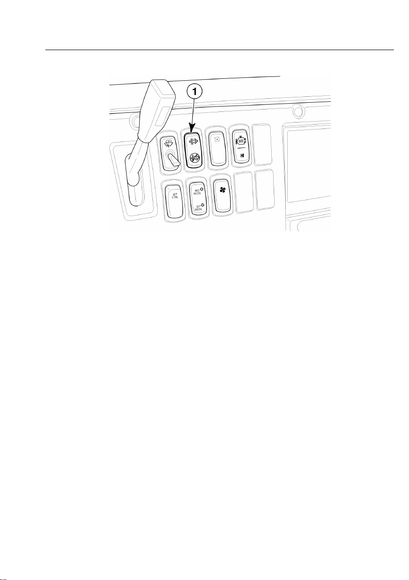
AftertreatmentDPFSmartSwitch(IfEquipped)
W2076076
AftertreatmentDPFSmartSwitch
TheaftertreatmentDieselParticulateFilter(DPF)smartswitchisathree-positionrocker
switchwheretheUPpositionismomentary ,theMIDDLEpositionisneutral(standby
mode)andtheDOWNpositionislocked.Theswitchallowstheoperatortointerfacewith
thevehicle'sexhaustaftertreatmentsystem.
Theswitchhasseveralfunctionsasoutlinedbelow.
•IndicatesthataanaftertreatmentDPFregenerationisneededorhasstartedwhenthe
iconsontheswitchareilluminated.
•IndicatesthataregenerationhasbeenstoppedwhentheDOWNpositionoftheswitchis
pressed,locked,andilluminated.
•StopsaregenerationeventwhentheDOWNpositionoftheswitchispressed,locked,
andilluminated.
•StartsanaftertreatmentDPFmanualregenerationeventwhentheswitchismomentarily
pressedtotheUPposition.
•GoesintostandbymodeandwaitsforregenerationwhentheswitchisintheMIDDLE
position.
Page 30

22V-MACCo-PilotOperator'sManual
C0035425
DPFSmartSwitch
ForadditionalinformationontheAftertreatmentDPFSmartSwitchandRegeneration,
pleasereferto“EXHAUSTAFTERTREATMENTSYSTEM”,page23.
Page 31

V-MACCo-PilotOperator'sManual23
EXHAUSTAFTERTREATMENTSYSTEM
AftertreatmentDPFRegeneration,CumminsISX
ADPFintheexhaustisusedtomeetemissionrequirementstohelpreducesootand
particulateemissionsintotheatmosphere.Theparticulatesaretypicallyremovedby
collectinginaDPF,withcontinuousorperiodicregenerationofthelter.Theelectrical
andexhaustaftertreatmentsystemsetupofthevehiclewilldeterminewhenregenerationis
required.Whenregenerationisneeded,theiconsontheDPFSmartswitchwilllightup
momentarilytonotifythedriverandthenshutoffduringregeneration.TheHighExhaust
SystemTemperature(HEST)indicatorwilllightupontheinstrumentclustertowarnofhigh
exhausttemperatures(whenvehiclespeedislessthan8km/h[5mi/h],dependingonengine
setting,orwhenparked).Dependingonthevehicle'saftertreatmentsetup,regenerationcan
beperformedwhilemovingorwhenthevehicleisparked.Belowisgeneralinformation
abouttheexhaustaftertreatmentsystems.
Forcatalyzedexhaustaftertreatmentsystems
•EngineCoolantT emperature(ECT)is35°C(95°F)orhigher.
•IconsontheDPFSmartswitchwillmomentarilylightupandthenshutoffduringthe
regeneration.
•HESTindicatoroninstrumentclusterwilllightuptowarnofhighexhausttemperatures
whenvehiclespeedis8km/h(5mi/h)orless,dependingonenginesetting.
•Enginespeedwillincreasetoaround1,100RPMduringregeneration(forparked
regeneration).
Page 32

24V-MACCo-PilotOperator'sManual
AftertreatmentDPFPassiveRegeneration,Cummins
ISX
AftertreatmentDieselParticulateFilter(DPF)passiveregenerationisautomatic(nooperator
inputneededtostartregeneration).Theoperatorisnotiedthataregenerationisneeded
whentheiconsontheDPFSmartswitchilluminate.
PleaserefertotheinstructionsbelowonhowtousetheDPFSmartswitchforpassive
regenerations.
Passive(Automatic)Regeneration
1WhentheiconsontheDPFSmartswitchlightup,maintainvehiclespeed.
2Duringregeneration,theiconsontheswitchwillshutoff.
3Iftheregenerationprocessneedstobestoppedandperformedatalatertime,pleaserefer
to“AftertreatmentDPFInhibit/StopRegeneration”,page26forinformation.
Page 33

V-MACCo-PilotOperator'sManual25
AftertreatmentDPFParkedRegeneration,Cummins
ISX
AftertreatmentDieselParticulateFilter(DPF)parkedregenerationallowstheoperatorto
startand/orstoptheregenerationmanuallywhenthevehicleisparked.Theoperatoris
notiedthataregenerationisneededwhentheiconsontheDPFSmartswitchilluminate.
Theoperatorshouldperformtheregenerationassoonaspossible.
PleaserefertotheinstructionsbelowonhowtousetheDPFSmartswitchforparked
regenerations.
1Movethevehicletoasafelocation,applytheparkbrakeandallowtheenginetoidle.
Note:Whenaregenerationisinprocess,theengineexhaustgastemperature(EGT)
willbeelevated.DONOTparkthevehiclewiththeexhaustoutletunderlowhanging
overheadammableobjectssuchastrees,awnings,etc.,thatcouldbedamagedby
elevatedexhausttemperatures.DONOTattempttoregenerateinsideagarageor
enclosedareaifthetailpipeisattachedtoanexhaustventilationsystemasthehose
materialmaynotberatedforthehightemperature.
2PressandholdthetoppartoftheDPFSmartswitchmomentarilytoinitiatethe
regeneration.
3Duringregeneration,theiconsontheswitchwillshutoff.TheHighExhaustSystem
Temperature(HEST)indicatorontheinstrumentclusterwilllightuptonotifyofhigh
exhausttemperatures.
4Forcatalyzedexhaustaftertreatmentsystems,theenginespeed(RPM)willrampupto
around1,100RPM.
5Regenerationcantakebetween45and90minutestocomplete.
6Afterregenerationhascompletedandtheexhausttemperaturehasreturnedtonormal,
theHESTindicatorwillshutoff.
7Iftheregenerationprocessneedstobestoppedandperformedatalatertime,pleaserefer
to“AftertreatmentDPFInhibit/StopRegeneration”,page26forinformation.
CAUTION
FailuretoperformanaftertreatmentDPF
regenerationinatimelymannerafter
noticationmayresultinenginederate,
cloggedordamagedDPF ,andengine
shutdown.
Page 34

26V-MACCo-PilotOperator'sManual
AftertreatmentDPFInhibit/StopRegeneration
AftertreatmentDieselParticulateFilter(DPF)regeneration,whetherthemovingor
parkedvariety ,canbestoppedifthevehicleisequippedwithaDPFSmartswitch(refer
to“AftertreatmentDPFSmartSwitch(IfEquipped)”,page21formoreinformation).A
regenerationshouldbestoppedonlywhennecessary .Tostoparegenerationthatisin
progress,presstheDPFSmartswitchtotheDOWNposition.Theswitchwilllockintothe
DOWNposition,andtheicononthebottomoftheswitchwillbeilluminatedtoindicate
regenerationhasbeenstopped.
C0035426
Inhibit/StopRegeneration
CAUTION
WhentheDPFSmartSwitchispressed
totheDOWNposition,theswitchwill
remainlockedinthispositionandprevent
aftertreatmentDPFregenerationfrom
occurring.Therefore,itisimportantto
presstheswitchbacktothemiddleposition
andtoreturnittostandbymodewhensafe
todoso.Failuretosettheswitchbackto
theMIDDLEpositionmayresultinengine
derate,acloggedAftertreatmentDiesel
ParticulateFilter(DPF),damagetothe
lterandengineshutdown.
Iftheoperatorstopsorinhibitsregenerationrepeatedly,theDPFwillbegintoclogwith
sootandengineexhaustgaspressurewillincrease.Eventuallytheenginewillderateand
ultimatelyshutdown.Belowisaquicklookatthetypeofregenerations,conditionsofthe
exhaustaftertreatmentsystemandtheactiontobetaken.
CAUTION
FailuretoperformaaftertreatmentDPF
regenerationinatimelymannermayresult
inenginederate,acloggedordamaged
DPF,damagetothelterandengine
shutdown.
Page 35

AFTERTREATMENTDPFP ASSIVEREGENERATION(AUTOMATIC)
SootLoad
Level
Indicators
Level1Level2
(Solid)
(Flashing) (Flashing)
Level3Level4
(Amber)
(Flashing)
(Red)
V-MACCo-PilotOperator'sManual27
Aftertreatment
System
Condition
Regenerationneeded.
DPFisbecomingfull.
Regenerationis
required.
DPFisfull.
AftertreatmentSystemServiceRequired.
EngineDerateActive.
EnginePerformanceislimited.
SootLevelHigh.
DPFisoverfull.
Note:TheRegenerationSymbolistheDPFsmartswitchnottheclusterwarninglight.
AftertreatmentSystemServiceRequired.
EngineDerateActive.
SootLevelisCriticallyHigh.
DPFmaybeoveritsmaximumcapacity.
Enginemayshutdown.
Page 36

SootLoad
Level
ActiontoTakeContinuetodriveor
Level1Level2
parkthevehiclein
asafelocationaway
fromoverhanging
objects(parkbrake
applied)andallow
theenginetorunand
theregenerationto
complete.
AFTERTREATMENTSYSTEMP ASSIVEREGENERA TION(AUTOMATIC)
Level3Level4
Continuetodriveor
parkthevehiclein
asafelocationaway
fromoverhanging
objects(parkbrake
applied)andallow
theenginetorunand
theregenerationto
complete.
Performaparkedmanualregeneration
IMMEDIATEL Ytoavoidfurtherengine
derateanddamagetotheDPF .
Note:Failuretoperformthe
regenerationwilltakethe
AftertreatmentSystemtoLevel4.
28V-MACCo-PilotOperator'sManual
Aseriousengineproblemhasoccurred.
Seekserviceimmediately.
Note:Parkedregenerationisno
longerpossiblefortheoperator .
Note:Failure
toperformthe
regeneration
willtakethe
Aftertreatment
SystemtoLevel2.
Regeneration
Condition
Ifpassiveregenerationisallowedtorun,thefollowingnormalprocessesmaybeobserved.
Note:Failure
toperformthe
regeneration
willtakethe
Aftertreatment
SystemtoLevel3.
•DPFSmartswitchindicatorwillshutoffduringtheregeneration.
Page 37

AFTERTREATMENTSYSTEMPARKEDREGENERA TION(MANUAL)
SootLoad
Level
Indicators
Level1Level2
(Solid)
(Flashing) (Flashing)
Level3Level4
(Amber)
(Flashing)
(Red)
V-MACCo-PilotOperator'sManual29
Aftertreatment
System
Condition
Regenerationneeded.
AftertreatmentDiesel
ParticulateFilter
(DPF)isbecoming
full.
Regenerationis
required.
DPFisfull.
AftertreatmentSystemServiceRequired.
EngineDerateActive.
EnginePerformanceislimited.
SootLevelHigh.
DPFisoverfull.
AftertreatmentSystemServiceRequired.
EngineDerateActive.
SootLevelisCriticallyHigh.
DPFmaybeoveritsmaximumcapacity.
Enginemayshutdown.
Page 38

AFTERTREATMENTSYSTEMPARKEDREGENERA TION(MANUAL)
SootLoad
Level
ActiontoTakeParkthevehiclein
Level1Level2
asafelocationaway
fromoverhanging
objects(parkbrake
applied).
Pressandholdthe
topoftheDPFSmart
switchmomentarily .
AllowtheDPF
regenerationprocess
tocomplete.
Parkthevehiclein
asafelocationaway
fromoverhanging
objects(parkbrake
applied).
Pressandholdthe
topoftheDPFSmart
switchmomentarily .
AllowtheDPF
regenerationprocessto
complete.
Level3Level4
PerformaparkedaftertreatmentDiesel
ParticulateFilter(DPF)regeneration
IMMEDIATEL Ytoavoidfurtherengine
derateanddamagetotheDPF .
Note:Failuretoperformthe
DPFregenerationwilltakethe
AftertreatmentSystemtoLevel4.
30V-MACCo-PilotOperator'sManual
Aseriousengineproblemhasoccurred.
Seekserviceimmediately.
Note:ParkedDPFregenerationis
nolongerpossiblefortheoperator.
Note:Failure
toperformthe
regeneration
willtakethe
Aftertreatment
SystemtoLevel2.
Note:Failure
toperformthe
regeneration
willtakethe
Aftertreatment
SystemtoLevel3.
Page 39

AFTERTREATMENTSYSTEMPARKEDREGENERA TION(MANUAL)
Aftertreatment
DieselParticulate
Filter(DPF)
regeneration
Condition
IfparkedmanualaftertreatmentDieselParticulateFilter(DPF)regenerationisallowedtorun,thefollowingnormalprocessesmaybe
observed.
•Enginespeed(RPM)willincreasetoaround1,100RPMandstaythereuntiltheDPFregenerationprocessis
complete.**
•HESTindicatorwillturnontowarnofhighengineexhaustgastemperature(EGTandwillstayonduring
aftertreatmentDieselParticulateFilterDPFregeneration.
•DPFSmartswitchindicatorwillshutoffduringtheaftertreatmentDieselParticulateFilter(DPF)regeneration.
•AftertreatmentDieselParticulateFilter(DPF)regenerationcantakebetween45and90minutestocomplete.
•HESTindicatorwillturnoffafteraftertreatmentDieselParticulateFilterDPFregenerationiscompleteand
exhausttemperatureshavereturnedtonormal.
**Enginespeedwillincreaseconditionforcatalyzedexhaustaftertreatmentsystems
V-MACCo-PilotOperator'sManual31
Page 40

32V-MACCo-PilotOperator'sManual
AftertreatmentDPFRegenerationandPTOOperation
(CumminsISX)
ThePTOmustbedisengagedforaftertreatmentDieselParticulateFilter(DPF)regeneration
tooccur.
STARTINGTHEVEHICLE
ThefollowingprocedureisusedtostartandwarmupaV ehicleManagementandControl
(V-MAC)IVengineduringanyAmbientAirTemperature(AA T)condition:
Note:Releasetheclutchandmakesurethetransmissionisinneutralbeforestartingthe
engine.
1TurntheignitionkeytotheONpositionclockwise.Whenthe“WaittoStart”indicator
ontheinstrumentclustershutsoff,fullyengagethestarter.Releasetheignitionkeyas
soonastheenginestarts.
Note:Iftheenginedoesnotstartimmediately,limitcrankingperiodsto30secondsto
avoidoverheatinganddamagingthestarter.
2Aftertheenginehasstarted,warmtheengineuntilEngineCoolantTemperature(ECT)
reaches60°C(140°F).Afterreaching60°C(140°F),theenginecanbeoperatednormally.
Note:Iftheenginedoesnotstartimmediately,limitcrankingperiodsto30secondsto
avoidoverheatinganddamagingthestarter.
Note:Warm-uptimecanbereducedbyincreasingengineidlespeedbetween1000–1200
RPMbyeitherapplyingthethrottlepedalorbyusingthevariablespeedgovernor(electronic
handthrottle)feature.Whenoperatingunloaded,theenginemayalsobewarmedbymoving
thevehicle(afteroneminuteofidlingtime)witha“light”throttleapplicationonly.
Note:StarterProtectionwilllimitcrankingtimetoavoidoverheatingthestarter.Ifthe
starterhasoverheated,itwillbeforcedoffuntilithascooled.
Page 41

V-MACCo-PilotOperator'sManual33
CRUISEANDENGINESPEEDCONTROL
WithV ehicleManagementandControl(V-MAC)IV ,theoperatorhastheabilitytoprecisely
controlenginespeed(RPM)andsetcruisecontrolspeeds,aswellassettingtheenginelow
idlespeed.Thesefunctionsareperformedbyusingthespeedcontrolswitcheslocatedon
thedashboard.Instructionsforsettingcruisecontrolandenginespeedcontrolaregiven
onthefollowingpages.Foranexplanationofenginelowidleadjustment,referto“Low
IdleAdjustment”,page44.
W2076074
SpeedControlSwitches
CruiseControl
EngagingCruiseControl
ThespeedcontrolfunctionsoftheV-MACIVsystemareverysimilartothecruisecontrols
foundonmostautomobiles.Thesystemwillmaintainasetspeedandwillallowacceleration
anddecelerationthroughthesystemswitches.Cruisecontrolcanbeenabledordisabled
usingcustomerdataprogramming,includedintheVCADSsoftware.
Tosetthecruisecontrolfornormalhighwayoperation,thefollowingconditionsmustbemet.
1Vehicleroadspeedmustbeabovethecustomer-programmablespeedvalue(15to35
mi/h).
2Theserviceandparkingbrakemustnotbeapplied.
3Theclutchmustbeengaged(pedalreleased).
Page 42

34V-MACCo-PilotOperator'sManual
EffectiveAugust11,2008,achangewasmadetotheV ehicleElectronicControlUnit
(VECU)softwarewhichaffectsthecruisecontrol.Asanaddedtesttoensurethattheservice
brakeswitchisfunctional,thevehicleoperatormustpressandreleasethebrakepedalafter
theenginehasbeenstarted.Thistestveriesthattheservicebrakeswitchisfunctioning.
Thetestalsoconrmsthatthecruisecontrolwilldeactivatewhentheservicebrakesare
applied.Ifthebrakepedalisnotdepressedafterstartingtheengine,thecruisecontrol
willnotfunction.Thischangeaffectsbothnewlymanufacturedvehicles,andvehicleson
whichtheVECUhasbeenreprogrammed.
Note:ForvehiclesmanufacturedpriortoAugust11,2008theVECUhasbeen
reprogrammed.
Oncetheaboveconditionsaresatised,activatethecruisecontrolasfollows.
1MovetheSpeedControlON/OFFswitchtotheONposition.
2Atthedesiredroadspeed,pressandreleasetheSETswitch.Thevehiclewillmaintainat
thesetspeed.
Note:PressingthetopoftheSpeedControlON/OFFswitchactivates,orturnstheswitch
ON.Pressingthebottomoftheswitchdeactivates,orturnstheswitchOFF.
Note:Toshift,simplydisengagetheclutch,changegears,thenre-engagetheclutch.Cruise
controlwillresumeautomaticallyifprogrammedtoAutoResume.Whendoubleclutching,
DONOTbringtheclutchpedaltothefullyengagedposition.
Page 43

V-MACCo-PilotOperator'sManual35
CAUTION
Transmissiongearchangesmustnotbe
madewithouttheuseoftheclutchwhilein
thecruisecontrolmode.Failuretousethe
clutchwillcausetheenginespeed(RPM)
toincreasetothehighidlelimit,which
maycauseseverepowertraindamage.
SpeedControlOn/OffandSet/DecelSwitches
W2076078
Page 44

36V-MACCo-PilotOperator'sManual
AcceleratingtoaHigherSpeed
Toacceleratetoahigherspeed,threemethodsareavailable:
1.PresstheAcceleratorPedal(AP).Thismethodwillacceleratethevehicleforaslongas
thepedalispressed.(Releasethepedaltoreturntothespeedsetpreviously .)
2.PresstheACCELswitch.Thismethodwillacceleratethevehicleforaslongasthe
switchispressed.Thenewvehiclespeedissetwhentheswitchisreleased.(Pressthe
DECELswitchtodeceleratethevehicle.Thevehiclewilldecelerateforaslongasthe
DECELswitchispressed.Thenewvehiclespeedissetwhentheswitchisreleased.)
Note:TheMAXspeedsetbytheaccelerator
pedalmaybedifferentfromthatsetbythe
ACCELswitch.
3.Thespeedcanalsobe“bumped”(knownasbumpspeed)upordown.TaptheACCEL
sidetobumpup1mi/hortaptheDECELsidetobumpdown1mi/h.
SpeedControlOn/OffandResume/AccelSwitches
W2076079
Page 45

V-MACCo-PilotOperator'sManual37
DisengagingCruiseControl
Todisengagecruisecontrol,useanyoneofthefollowingmethods:
1Applytheservicebrake.Thismethodwilldisengagethecruisecontrolwhile
maintainingthesetspeedinthesystemmemory.Toresumethepreviouslysetspeed,
pressandreleasetheRESUMEswitch.
2Disengagetheclutch.Thismethodwilldisengagethecruisecontrolwhiletheclutch
isdisengagedandwillresumethespeedcontrolwhentheclutchisre-engaged.This
programmableoptionprovidesforautomaticresumeaftershifting.
3MovetheSpeedControlON/OFFswitchtotheOFFposition.Thismethodnotonly
disengagesthecruisecontrolbutalsoclearsthesetspeedfromthesystemmemory .To
reactivatethecruisecontrol,itisnecessarytomovetheswitchtotheONpositionand
selectanewsetspeed.
SpeedControlON/OFFSwitch
W2076079
Page 46

38V-MACCo-PilotOperator'sManual
EngineSpeedControl
EngineSpeedControlOperation
TheV ehicleManagementandControl(V-MAC)IVsystemalsoallowstheoperatortoset
andmaintainincreasedenginespeeds.Thesystemprovidestwodifferentspeedcontrol
functions:ElectronicHandThrottlecontrolandPTOcontrol.ElectronicHandThrottle
(EHT)controlsenginespeedwhenPTOisnotengaged.
Bothsystemsallowtwomodesofcontrol:
1SingleSpeedControl(SSC)increasestheengineRPMtoaspeedpreprogrammedintothe
systemmemory.ThismodeisintendedforoperationofthePTOatmaximumefciency.
2VariableSpeedControl(VSC)allowsthedrivertosetanyengineRPMwithinthe
preprogrammedlowandhighlimitssetinthesystemmemory .Thismodeisprimarily
intendedforgeneralPTOapplicationsandenginewarm-up.
Note:Brakeconditionsarecongurable,butthestandardsettingisparkbrakeonand
servicebrakeofftoengage.
SingleSpeedControl(SSC)
Tousesinglespeedcontrolfunctions,thefollowingconditionsmustbemet:
1ForPowerTakeoff(PTO)operation,thePTOmustbeengaged.ForElectronicHand
Throttle(EHT)operation,theservicebrakemustbeOFF.
2Theclutchmustbeengaged(notpressed).
ToactivateSSC,movetheSpeedControlswitchtotheONposition,thenpressandrelease
theSETswitch.Theenginespeed(RPM)willjumptothepreprogrammedspeed.SSCcan
alsobeprogrammedforAutoSetmode.Whenenabled,simplymovetheSpeedControl
switchtotheONpositionandengagethePTOoractivateacustomer-denedswitch(usually
settingtheparkbrake).Enginespeedwillgotothepreprogrammedspeed.
Page 47

V-MACCo-PilotOperator'sManual39
VariableSpeedControl(VSC)
Tousethevariablespeedcontrolfunctions,thefollowingconditionsmustbemet:
1Theclutchmustbeengaged.
2Theparkbrakemustbeset.
ToactivateVSC,movetheSpeedControlswitchtotheONposition.IncreaseengineRPM
usingtheacceleratorpedal(AP).Atthedesiredenginespeed(RPM),pressandreleasethe
SETswitch.Thisspeedsettingwillbemaintained.
ToincreasetheRPM,pressandholdtheACCELswitchuntilthedesiredspeedisattained.
Or,presstheacceleratorpedaluntilthedesiredspeedisattainedandthenpressandrelease
theSETswitch.
TodecreaseengineRPM,pressandholdtheDECELswitchuntilthedesiredspeedis
reachedandthenreleasetheswitch.
RPMcanalsobe“bumped”upordown.TaptheACCELsidetoincreaseRPM,orthe
DECELsidetodecreaseRPMbythecustomer-programmedamount(defaultsettingis
50RPM).
VSCcanalsobeprogrammedforAutoSetmode.Whenenabled,simplymovetheSpeed
ControlswitchtotheONpositionandactivateacustomer-denedswitch(usuallysetting
theparkingbrake).TheRPMwillgotothepreprogrammedminimumspeed.
The“ramprate”forEHT,andforeachPTOinPTOcontrol,canbeprogrammedtoincrease
anddecreaseinspeedtoacustomer-speciedspeedbyusingtheACCEL/DECELswitch.
DisengagingSSCorVSCFunctions
Todisengagethespeedcontrolsettings,useanyoneofthefollowingmethods:
•MovetheSpeedControlswitchtotheOFFposition.
•Disengagetheclutch.
•Applytheservicebrakes.
•Releasetheparkingbrake.
Note:WhenthePTOisengagedonvehiclesequippedwithSSC,theSSCwilltake
precedenceovertheVSC.
Note:ToreactivatetheVSCtothepreviouslysetspeed,pressandreleasetheRESUME
switch.IftheSpeedControlON/OFFswitchisusedtodisengagetheVSC,anewspeed
mustbeset.TheRESUMEswitchwillworkonlyiftheVSCwasdisengagedbyusing
theclutchorservicebrake.
Page 48

40V-MACCo-PilotOperator'sManual
MaximumEngineSpeedLimit
Thismodeallowsthemaximumenginespeed(RPM)tobelimited,basedonpreprogrammed
speeds,whenPTOorElectronicHandThrottle(EHT)controlsareengaged.Theenginewill
notoperatebeyondthesespeedswhenthecontrol(PTOorEHT)isengaged.Theoperator
hasnocontroloverthisoperation,andcannotchangeoroverridethesepresetlimits.
VehicleLimitingSpeed
Theseprogrammablemodesallowthemaximumvehiclespeedtoberestrictedtoa
preprogrammedspeedlimit.Thedriverhasnocontroloverthisoperation,andcannot
changeoroverridethesepresetlimits.Anotherfeatureofthevehiclelimitingspeedfunction
is“LowerGearRoadSpeedLimitFeatureActivation.”Thisoption,whenselected,will
limitvehiclespeedingearsbelowtopgeartoavaluelessthanthetopgearroadspeedlimit.
Thepurposeofthisoptionistoencouragetheoperatortooperatethevehicleintopgear,
wheretheoptimumfueleconomycanbeachieved.
Therearetwoprogrammable“topgear”V ehicleLimitingSpeeds—oneforcruiseandthe
otherforusewiththeAcceleratorPedal(AP).
VehicleLimitingSpeedcanalsobelimitedtoseparatevaluesforeachPowerTakeoff(PTO).
Note:Thevehiclelimitingspeedincruisecontrolmodecanbelowerorequaltothevehicle
limitingspeedinacceleratorpedalmode.
HighAccelerationControl
Underlightloadandhighvehicleaccelerationconditions,themaximumengineacceleration
maybelimitedtopreventwheelslippage.Enginespeed(RPM)willbelimitedtoavalue
justabovetheratedspeedoftheengine.
Thisconditionshouldnotpreventthedriverfromshiftingtothenextgear.Iftheengineis
limited,itisanindicationthatwheelslippageconditionsmaybepresentandthatthedriver
shoulddrivelessaggressivelyundertheselightlyloadedconditions.
Page 49

V-MACCo-PilotOperator'sManual41
EngineBrake
W2076080
EngineBrakeSwitch
Toactivatetheenginebrake,movetheenginebrakeswitchtothe1stor2ndONposition.
The1stpositionactivatestheenginebrakeunitfor50%power.The2ndpositionprovides
100%power.Theenginebrakeswitchcanbeineither1stor2ndONpositionduringspeed
controloperations,butthebrakewillfunctiononlyifnofuelisrequestedbyV ehicle
ManagementandControl(V-MAC)IVandenginespeed(RPM)isgreaterthan900RPM.
Todisengagethebrake,movetheswitchtotheOFFposition,orpresstheAccelerator
Pedal(AP).
Note:TheenginebrakewillnotengageuntiltheEngineOilTemperature(EOT)has
reached52°C(125°F).
ACCESSORYRELA YCONTROL
Afteranidleshutdown,V-MACIVwilldeactivatealltheignitionpowerbusrelays,butthe
EngineControlModule(ECM)powerrelaywillremainactiveinordertoreducecurrent
drawfromthebatteryaftertheenginehasstopped.
Page 50

42V-MACCo-PilotOperator'sManual
PROGRAMMABLEFEATURES
TheVehicleManagementandControl(V-MAC)IVsystemallowsoperatingparametersof
certainsystemfunctionstobeprogrammed.Thesefunctionsincludethefollowing:
•AudibleAlarm
•AutoStart(iTAS)[Optional;FutureSupport]
•AuxiliaryEngineStop(Optional)
•CruiseControlMaximumSpeed
•CruiseControlMinimumSpeed
•DrivelineParameters
•DriverDisplayParameters
•ElectronicHandThrottle(EHT)ControlParameters
•EngineBrakeDelayinCruise
•EngineGovernorParameters
•EngineProtectionParameters
•EngineSleepMode
•EngineSpeedControlParameters
•HighIdleSpeed
•FanControl
•FuelEconomyIncentiveParameters
•IdleCooldown
•IdleShutdown
•LowIdleSettings
•LowerGearRoadSpeedLimit
•ON/OFFFanControl
•OverspeedLogging
•PowerT akeoff(PTO)ControlParameters
•TamperDetection
•VehicleLimitingSpeedSettings
•VehicleSecurityLevel
•DriverPersonalOverspeedAlarm
Page 51

V-MACCo-PilotOperator'sManual43
Tochangeoperatingparameters,acomputerisusedandrequiresthatitisrunningthe
VCADSsoftware.Inaddition,adatalinkadapterisalsorequiredasaninterfacebetweenthe
scantoolandtheV ehicleManagementandControl(V-MAC)IVsystem.
Note:Ifthereartiresizesarechanged,ortherearaxleratiosarechanged,youmustcontact
yourlocalMACKTruckdealer.FailuretonotifyyourlocalMACKTruckdealerofthese
changesmaycauseinaccuratespeedometerreadings.
Page 52

44V-MACCo-PilotOperator'sManual
Cruise'NBrakeEngagementDelay
Withthecruise'nbrakeengagementdelayfeature,engagementoftheenginespeed(RPM)
isdelayedincruisecontroltoreduceenginebrakecycling.Thebrakewillengage3.2km/h
(2mi/h)abovethecruisesetspeed.Theenginebrakeoperatesnormallywhencruiseis
notbeingused.
EngineHighIdleSpeedifStopped
Maximumenginespeed(RPM)canbeadjustedbyusingVCADSsoftware.Thepossible
highidlesettingsrangefrom600to2,600RPM.However,theenginespeedwillnotgo
belowlowidleandwillnotexceedtheOEMhighidle(usually2,100or2,150RPM).
EngineHighIdleSpeedinUpperGears
SetsthemaximumengineRPMifthegearratioislessthan1.5.Thisfeatureisintendedto
improvefueleconomybylimitingefcienthighspeedengineoperation.
LowIdleAdjustment
Note:Onchassisequippedwithanautomatictransmission,thespeedcontrolswitches
cannotbeusedtoadjustenginelowidlespeed.Attemptingtosetlowidleinthismanner
willcausetheV ehicleElectronicControlUnit(VECU)toenterthereprogramming
moderesultingintheidlespeeddroppingto550RPM(650RPMfornon-catalyzed
exhaustaftertreatmentsystem),butitwillnotbepossibletosetanewidlespeed.Ifthe
reprogrammingmodeisentered,simplyturnthespeedcontrolswitchOFF,andidlespeed
willreturntotheoriginallysetspeed.Resettinglowidlespeedonachassisequippedwith
anautomatictransmissionrequiresascantoolrunningtheVCADSsoftware.Consultthe
VCADSUser'sGuideforadditionalinformation.
Page 53

V-MACCo-PilotOperator'sManual45
ThissectionexplainstheproceduretoresetthelowidlespeedusingtheSpeedControl
switches.
TheV ehicleManagementandControl(V-MAC)IVsystemallowsthelowidletobe
setwithintherangeof550to700RPM(650–700RPMfornon-catalyzedexhaust
aftertreatmentsystem).Thisprovidesexibilitytosetthelowidletothesmoothestengine
speedforthevehicle.
Therearetwostepsrequiredtoresetthelowidlespeed.TherststepplacestheV-MAC
IVsystemintothelow-idleadjustmode.Inthismode,V-MACIVisreadytoacceptthe
newidlespeed.
ThesecondstepistoactuallytellV ehicleManagementandControl(V-MAC)IVwhat
thenewidlespeedwillbe.
Therstphaseintheprocessismeetingtherequirementslistedbelow .
1TheV-MACIVsystemmusthavetheLow-IdleAdjustoptionenabledinthecustomer
dataspace.Thisfunctioncanbedisabledbythecustomer.
2Besuretherearenoactivefaultsinthesystem.
3Thevehiclemustbestationary.
4Theparkingbrakemustbeapplied.
5TheAcceleratorPedal(AP)mustbeattheidleposition(notpressed).
6TheSpeedControlON/OFFswitchmustbeturnedONandOFF3timeswithintwo
seconds.Atthispoint,theidlespeedwilldropto550RPM,andV-MACIVwillnowbe
readytoacceptanewspeed.BesuretoleavetheignitionkeyintheONposition.
SpeedControlSwitches
W2076074
Page 54

46V-MACCo-PilotOperator'sManual
Note:Iftheidlespeeddoesnotdropto550RPMaftermeetingtherequirementslisted,there
maybeotherpossibleproblemswhichwillnotallowtheidletobereset.RefertotheV ehicle
ManagementandControl(V-MAC)IVServiceManualfortroubleshootingprocedures.
Tocompletetheresettingoftheidlespeed,continueasfollows:
1Depressandholdtheacceleratorpedaluntilthedesiredenginespeedisreached.
2Usethespeedcontrolswitchestoadjustidlespeed.
3Depressandreleasetheclutchpedaltostoreidlespeed.
ThisspeedisnowlockedintoV-MACIVasthelowidlespeed.
Note:Todetectadropwhenresettingtheidle,itisrecommendedthatthelowidlespeedbe
settoaspeedgreaterthan500RPM.
SmartIdleElevatedIdleRPMTime
Thisfeaturewilldiscontinuearampupforaperiodoftimewhentheenginespeed(RPM)
reachesitstarget.Therangeoftimecanbesetbetween0and1092minutes,withadefault
settingof30minutes.
IdleShutdown
Thisfeaturewillshutofftheengineafterithasbeenidleforaspeciedperiod.Thetime
periodiscustomerprogrammableusingtheVCADSsoftware.Analarmwillwarn30
seconds(aprogrammabletimeframe)beforetheenginewillshutdown.Theidleshutdown
overrideswitchcanbeusedduringthis30secondperiodtooverrideidleshutdownorthe
servicebrakeorAcceleratorPedal(AP)canbeapplied.Oncetheengineshutsdown,the
enginecanbere-startedbyturningtheignitionkeytotheStartposition.
Note:Idleshutdownwillnot occurduringanaftertreatmentDieselParticulateFilter(DPF)
regeneration.IftheidleshutdowntimerrequestsashutdownduringaftertreatmentDiesel
ParticulateFilter(DPF)regeneration,theenginewillnotshutdownuntilafter
hasbeencompleted.
regeneration
Page 55

V-MACCo-PilotOperator'sManual47
SpeedSensorTamperDetection
Speedsensortamperdetectionisusedtomonitorandstopunauthorizedtamperingofthe
vehiclespeedlimitingfunctioninordertogainadditionaltopspeed.Iftamperingisdetected,
thevehicleoperatorwillbenotiedbyadiagnostictroublecode(DTC).Enginepowerwill
belimitedtoaprogrammedpercentageandwillcontinueuntiltheissuehasbeencorrected.
Note:T orquelimitingwillbeinhibitedifadriveshaftPowerTakeoff(PTO)isenabled
andactive.
Page 56

48V-MACCo-PilotOperator'sManual
ELECTRICALACCESSORYCONNECTIONPOINTS
ThisMACKchassisiselectricallyreadyforconvenientinstallationofelectricalaccessories.
Usethedesignatedbatterypost(+12V),groundpost,CBjack,bufferedRPMoutputs,
bufferedmi/houtputs,andtheSAE/A TAJ-1708postlocatedontheelectricalequipment
panelfortheinstallationofanyelectricalaccessories.Eachconnectionpointisdescribed
below.
BatteryPost(BATT)
Thisisa+12volt,unswitchedbatterypowerconnection.Itcanbeusedtopowerexternal
devicesthatrequirepoweratalltimes,evenwhentheignitionkeyisturnedOFF .This
sourceisprotectedbya15-ampcircuitbreaker .
IgnitionPost(IGN)
Thisisa+12volt,switchedbatterypowerconnection.Itcanbeusedtopowerexternal
devicesthatrequirepoweronlywhentheignitionkeyisON.Thissourceisprotectedby
a15-ampcircuitbreaker.
GroundPost(GND)
Thisisagroundconnection.Itcanbeusedasapowerreturn(−)connectionforexternal
devices.
RPMOutput
Thisisa50%dutycycle,5-voltTransistor-TransistorLogic(TTL)compatible,square-wave
signalthatiscalibratedtoprovideastandardpulserateof12pulsesperenginerevolution.
Note:Transistor-transistorlogiccompatibleofthisoutputmaybeaffectedbyotherdevices
connectedtothisoutput.MaximumratedcurrentoftheTTLoutputis10mA.T otalcurrent
drawofalldevicesconnectedtothisoutputmustnotexceed10mAat4volts.
Page 57

V-MACCo-PilotOperator'sManual49
Km/hOutput
Thisisa50%dutycycle,5-voltTTL-compatible,square-wavesignalthatiscalibratedto
provideastandardpulserateof30,000pulsespermile.
Note:TTLcompatibilityofthisoutputmaybeaffectedbyotherdevicesconnectedtothis
output.MaximumratedcurrentoftheTTLoutputis10mA.T otalcurrentdrawofall
devicesconnectedtothisoutputmustnotexceed10mAat4volts.
SAE/ATAJ-1708Posts(SeriesLinkAandB)
Thisisaserialcommunicationinterface.ItconformstotheSAE/A TAJ-1708Recommended
PracticeforSerialDataCommunicationsBetweenMicrocomputerSystemsInHeavyDuty
VehicleApplications.
CBRadioPowerJack(CBRadio+)(Locatedon
Dashboard)
Thisisa+12volt,switchedbatterypowerconnection.Itisusedtopowerthevehicle'sCB
radio.Itisprotectedbya15-ampcircuitbreakerandwillsupplypoweronlywhenthe
ignitionkeyisintheONposition.
CBRadioGroundJack(CBRadio−)(Locatedon
Dashboard)
Thisisagroundconnection.Itisusedasapowerreturn(−)connectionforthevehicle's
CBradio.
SeethefollowingillustrationsfortheCTPandCXPelectricalaccessoryconnectionpoints
forelectricalequipmentpanels.
Page 58

50V-MACCo-PilotOperator'sManual
INSTRUMENTCLUSTERDISPLAY
Theinstrumentclusterdisplayisanin-dashcomponentthatletsthedrivermonitor
informationsuppliedbyV ehicleManagementandControl(V-MAC)IVandalsopermits
thedrivertochangefunctionstoaccommodatehisneeds.Theinstrumentclusterdisplayis
userfriendlyandpromptsthedriverwithmessagesonthedriverinformationdisplay.
DashClusterSet-UpProgramming
Somefeaturesandfunctionslistedinthissectioncanbecustomizedtomeetcompanyor
driver'sneeds.V-MACIVcanbeprogrammedbythedealerorcustomerusingVCADS
softwaretomakethesefeaturesavailablethroughtheinstrumentcluster.
Page 59

V-MACCo-PilotOperator'sManual51
InstrumentClusterComponents
Thedashclusterconsistsofthefollowingeightmajorcomponents:functionlightindicators,
electronicmalfunctionindicator,engineshutdownindicator,driverinformationdisplay ,low
fuelindicator,gauges,speedometerandtachometer,OnBoardDiagnostic(OBD)faultand
warningindicators.Althoughnotapartofthedashclustercomponents,butnevertheless
partofthedashclustertool,isthestalkswitch(forCo-Pilot®only)locatedontheright
sideofthesteeringcolumn.
Thefollowingillustrationshowstheinstrumentclusterdisplay(Co-Pilot®shown).
InstrumentClusterComponents
Note:Theinstrumentclusterdisplayedismeantasageneralrepresentationonly.Avehicle's
specicinstrumentclusterisdependentontheemissionequipmentinstalled.
1.FunctionLightIndicators5.LowFuelIndicator
2.ElectronicMalfunctionIndicator
3.EngineShutdownIndicator7.SpeedometerandT achometer
4.DriverInformationDisplay8.WarningIndicators
6.Gauges
W3036320
Page 60

52V-MACCo-PilotOperator'sManual
Thefollowingillustrationshowsthestalkswitch.
C0035377
InstrumentClusterComponents
Thestalkswitch(forCo-Pilot®displayonly)islocatedontherightsideofthesteering
columnandcontainsthreedepressiblebuttons:ESC,Enter(↵ ↵↵)andUp&Down.Thestalk
switchisusedtoaccess,navigate,viewandchangeinformationavailableinthedriver
informationdisplay(Co-Pilot®display).
Page 61

V-MACCo-PilotOperator'sManual53
DriverInformationDisplay
ThedriverinformationdisplayavailableforMACKTrucks,vehiclesistheCo-Pilot®
Display.TheCo-Pilot®Displayprovidesthedriverwithsuchinformationastime,
temperature,tripmileage,tripfuel,warninginformationandDiagnosticTroubleCodes
(DTCs).Thedriverinformationdisplayalsocontainsamenuwherethedrivercanaccess
andadjustfunctionssuchasmaintenance,dashclusterself-test,alarmsound,lightinglevel,
time,languagechoice,andunitsofmeasure.Bothdriverdisplaysarelocatedinthecenterof
thedashclusterandeasilyaccessibletothedriver.
Toenterthedriverinformationdisplay,pressandholdtheEnter(↵ ↵↵)buttononthestalk
switch.
Formoreinformationregardingthedriverinformationdisplay,pleasereferto“CO-PILOT®
DISPLAY”,page58.
Page 62

54V-MACCo-PilotOperator'sManual
DiagnosticTroubleCodes(DTCs)
ElectronicDashDisplay
DTCsareusedforisolatingandtroubleshootinganyactivefaultsintheV ehicleManagement
andControl(V-MAC)IVsystem.ActiveDTCscanbequicklyviewedontheelectronic
dashdisplay(Co-Pilot)inthefollowingformat:
W3036575
DTCIndicator(J1587)
1MID—MessengerIdentierCode
2PID,PPID,PSIDorSID—ParameterIdentier,ProprietaryParameterIdentier,
ProprietarySubsystemIdentierorSubsystemIdentierCode
3FMI—FailureModeIdentier
Page 63

V-MACCo-PilotOperator'sManual55
W3036576
DTCIndicator(J1939)
1SA—SourceAddress
2SPN—SuspectParameterNumber
3FMI—FailureModeIdentier
TheActiveDTCscreens,indicatethatthereisanactivePID84faultfromtransmitter
128withanFMIof4.
ActiveDTCScreens
W3078076
Page 64

56V-MACCo-PilotOperator'sManual
SelectViewActiveFaultScreen
W3067831
DiagnosticSubmenuScreen
W3067829
Page 65

V-MACCo-PilotOperator'sManual57
ToviewtheDTCs(thevehiclemustbestationary),turntheignitionkeytotheONposition
anddothefollowing(refertoFigure33):
1PresstheEnter(↵ ↵↵)buttonontheStalkSwitch.TheCo-Pilotmainmenuwillappear.
2UsetheUp&DownbuttontohighlighttheDiagnosticsmenu.
1PresstheEnter(↵ ↵↵)buttontoentertheDiagnosticsmenu.
2UsetheUp&DownbuttontohighlightElectronicFaults.
3PresstheEnter(↵ ↵↵)buttontoentertheElectronicFaultsmenu.
4Youcanviewbothactiveandinactivefaultcodes(refertoFigure33,Figure35,and
Figure36,).
1Toviewactivefaultcodes,usetheUp&DownbuttontohighlightActiveFaultsand
thenpresstheEnter(↵ ↵↵)buttontoselect.
Note:ClearinginactivefaultcodesisonlypossibleifyouhaveOwner-Operating
programmingaccess.
2ToexittheCo-Pilot,presstheEnter(↵ ↵↵)buttonandthenpresstheESCbuttontwiceto
returntothemainmenu.
FormoredetailandgraphicpresentationonviewingDTC,pleasereferto“CO-PILOT®
DISPLAY”,page58.
Page 66

58V-MACCo-PilotOperator'sManual
CO-PILOT®DISPLA Y
IntroductionandPurpose
TheCo-Pilotisanin-dashcomputerthatletsthevehicleoperatormonitorinformation
suppliedbytheV ehicleManagementandControl(V-MAC)IVelectroniccontrolsystem
andenhancethefunctionsofV-MACbyenteringrequestedinformationwiththestalk
switch.TheCo-Pilotisvery“userfriendly”andpromptstheoperatorwithmessageson
thedisplayscreen.
BeginningwithCo-Pilot,featuresincludethefollowing:
•FuelEconomyInformation
•DriverTripandFleetTripInformation
•SpeedometerInformation
•GaugeInformation
•ElectronicFaults
•DriverMessages
•ClusterDiagnostics
•MaintenanceMonitoring(ifavailable)
•Set-Up(languages,units,driveroverspeedalarm,date,displaylighting)
Page 67

V-MACCo-PilotOperator'sManual59
CO-PILOTSYSTEMOVERVIEW
Set-UpProgramming
ManyCo-PilotfeaturesandfunctionslistedinthisOperator'sGuidecanbecustomizedto
meetindividualcompanyoroperatorneeds.V-MACcaneasilybeprogrammedbythe
dealerorcustomerusingMACK'sscantoolwithVCADSsoftwaretomakethesefeatures
availablethroughtheCo-Pilot.
IfyourCo-PilotdoesnotdisplayanyofthefeatureslistedinthisOperator'sGuide,
pleaseconsultyourdealerorappropriateeetmanagementpersonnelforV-MACset-up
reprogrammingasrequired.ProgrammableCo-Pilotfeaturesinclude:
W3077546
Page 68

60V-MACCo-PilotOperator'sManual
Table4ProgrammableCo-PilotFeatures
Feature
BillofLadingEnterinBillofLadingnumberN/A
ChangeDriverChangetoanewDriverEnabled
DrainW ater(optionalandfor
possiblefuturesupport)
DriverOverspeedAlarm(for
futuresupport)
IntegratedT emp-A-Start
(optional)
MaintenanceResetResetMaintenanceitemsDisabled
DELMessages
NextFleetTripEnterthenexteettripDisabled
ResetDriverTripResetDriverTripinformationEnabled
SetDisplaySettings
Function/SelectionsFactoryDefaultSettings
Drainsthesedimentbowl
automaticallyfrommenu
command
Setpersonalvehiclespeed
thresholdalarm
ProgramsettingsIfordered,thereareseveral
DriverentersinDriverEvent
LoggingMessages
•SetCo-Pilottimeand
date
•Setlanguage
•Setdisplaylighting,
brightnessandcontrast
•Setunitsofmeasure
HoursofService(forfuture
support)
——
Enabledautomaticallyifthe
optionisordered
parametershere.
Disabled
N/A
English
N/A
Englishunitsofmeasure
ThefollowingillustrationshowstheareasoftheCo-Pilot®CurrentConditionsscreen.
Page 69

V-MACCo-PilotOperator'sManual61
Co-PilotCurrentConditionsScreen
W3075369
1.Time
2.Mileage
3.AmbientAirTemp(AA T)
4.InformationArea
5.SweetSpotIndicator
6.Bonus/Penalty(IfAvailable)
7.EngineBrake
8.Maintenance
9.Overspeed/Idle
10.Gear(withautomatedtransmission)
11.ActiveCruiseControl(IfFitted)
12.ActiveCruiseControlTarget
Detected(IfFitted)
Page 70

62V-MACCo-PilotOperator'sManual
Thestalkswitchislocatedontherightsideofthesteeringcolumnandcontainsthree
depressiblebuttons:ESCEnter(↵ ↵↵)andUp&Down.Thestalkswitchisusedto
access,navigate,viewandchangeinformationavailableinthedriverinformationdisplay
(Co-Pilot®only).
•TheEscorEscapebutton(1)isusedtoreturntothepreviousmenuordisplay ,orto
cancelasettingoroperation.
•TheEnterbutton(3)isusedtodisplayalistofmenus,openamenu,andselectachosen
value.
•TheUparrow(2)isusedtoscrollupthroughamenuandtoincreasenumericalvalues.
•TheDownarrow(2)isusedtoscrolldownthroughamenuandtodecreasenumerical
values.
Thefollowingillustrationshowsthestalk
switch.
StalkSwitch(Co-PilotOnly)
C0035377
Page 71

V-MACCo-PilotOperator'sManual63
CO-PILOT®OPERATIONS
Thischapterisintendedasageneraloverviewtooperations.
UsingtheCo-Pilot®
Note:TurntheignitionkeytotheON
positionbeforeoperatingtheCo-Pilot®.
WhentheignitionkeyisturnedtotheONposition,theCo-Pilot®automaticallyturnson.
TheMACKLogoIntroscreenappearsforseveralsecondsandisusuallyfollowedbythe
lastAnytimescreenthatwasactivepriortopower-down.IfV ehicleManagementand
Control(V-MAC)IVisprogrammedto“getdriver”atkey-on,thentheCHANGEDRIVER
screenwillappear.MessagesonthescreenwillpromptthedrivertopresstheEnter(↵ ↵↵)
buttontoacceptthedriverIDorusetheCo-Pilot®stalkswitchtoenterapassword.
RemembertopressandholdtheEnter(↵ ↵↵)buttonbeforebeginningatriptomakethe
stationary MAINMENUscreenappear .
Note:Ifthescreenisblack,presstheEnter(↵ ↵↵)buttononthestalkswitchtoturniton.
Note:Itisalsopossibletoretrieveenginehoursandodometerreadingswiththeignition
OFF;simplypressandholdtheEnter(↵ ↵↵)buttononthestalkswitch.
Page 72

64V-MACCo-PilotOperator'sManual
CO-PILOTSYSTEMOVERVIEW
ESCButton
TheESC(Escape)buttononthestalkswitchtakestheCo-Pilotbacktothepreviousscreen
orlevelinthemenu.
Note:TheESCbuttondoesnotfunctionat
Start-Up.
Enter(↵ ↵
TheEnter(↵ ↵↵)buttononthestalkswitchselectsthehighlightedmenuitemsduringmenu
selection.DuringStart-Upandwhenmovingthevehicle,theEnter(↵ ↵↵)buttonisalsoused
toconrmoracknowledgeapop-upscreen.Sometimes,theEnter(↵ ↵↵)buttontakesthe
Co-Pilotdisplaybacktothepreviousscreen.
↵
)Button
Up&DownButtons
TheUp&Downbuttonsattheendofthestalkswitchallowtheusertohighlightthevarious
availablemenuitems.Sometimes,thesebuttonsareusedtoenterinformationintothe
displays.
•UpButton—Onceatthetopofthemenuitemsthatcanbeselected,pressingtheUp
buttonwilltaketheCo-Pilotdisplaytothelastiteminthemenu.
•DownButton—Onceatthebottomofthemenuitemsthatcanbeselected,pressingthe
DownbuttonwilltaketheCo-Pilotdisplaytotherstiteminthemenu.
Page 73

V-MACCo-PilotOperator'sManual65
CO-PILOT®LA YOUT
ScreenTypes
TheCo-Pilot®containssixtypesofdisplayscreens:
•Start-UpScreens—Agroupofscreensthatappearwhenthevehiclemanagementand
controlvehiclemanagementandcontrol(V-MAC)IVsystemisenergized.Individual
Start-Upscreensarediscussedinmoredetailin.
•MenuScreens—Agroupofscreensthatappearwithamenuselectiondependingon
whetherthevehicleisstationaryormoving.IndividualMenuScreensarediscussed
inmoredetailin.
•AnytimeScreens—Agroupofscreensthatcanbedisplayedtoadriveratanytime
(whetherthevehicleismovingorstationary).IndividualAnytimeScreensarediscussed
inmoredetailin.
•StationaryScreens—Agroupofscreensthatisonlyaccessiblewhenthevehicle
isstationary(V ehicleSpeed=0).Thesescreenchoicesdisappearfromthestationary
MAINMENUscreenwhenthevehiclebeginsmovingandarereplacedwiththelast
anytimescreen.IndividualStationaryScreensarediscussedinmoredetailin.
•InterruptScreens—Agroupofspecialscreensthatappearsduringstart-uporoperation
tonotifythedriverofcertaincriticalinformation.WhenanInterruptscreenappears,the
drivermustdooneofthreethings:
1Key-intherequestedinformation.
2PresstheEnter(↵ ↵↵)buttontoacknowledgethescreenandturnoffthewarning
and/oralarm.
3Takeappropriateactiontocorrecttheconditionthattriggeredthealarm.
Forexample,iftheDRIVERROADSPEEDALARMscreenappears,decelerateuntilthe
vehiclespeeddropsbelowthelimitwhichtriggeredthealarm.
IndividualInterruptScreensarediscussedinmoredetailin.
•OptionalSystemsScreens—Agroupofspecialscreensthatareaccessibledepending
uponavailability.
IndividualOptionSystemsScreensarediscussedinmoredetailin.
Page 74

66V-MACCo-PilotOperator'sManual
Driver'sIDScreens
ThefollowingscreensallowadriverspecicIDtobeenteredviatheDriverInformation
Display.Thisoptionallowsvariousvehicleinformationtoberecordedforthedriver
associatedwiththedriverID.TheIDcanbechangedfromtheDriverInformationDisplay
(DID)usingthestalkswitchcontrollever .
IfthevehiclehastheDriverIDfeature,whenthevehicleisstartedtheEnterDriverID
screenappearsintheDID.TheoperatorenterstheappropriatedriverIDatthattime.
1TherstnumberwillbehighlightedintheDIDscreen.Usetheupanddownarrowsof
thestalkswitchcontrollevertoscrolltotheappropriatenumber.
2Oncethecorrectnumberisfound,presstheEnterbuttononthestalkswitchcontrollever.
3ThenextnumberintheDriverIDsequenceishighlighted.Enterallthenumbersfor
theDriverIDusingthesesteps.
W3067466
Page 75

V-MACCo-PilotOperator'sManual67
OncetheDriverIDhasbeenenteredpresstheEnterbuttononthestalkswitchcontrollever.
TheCommandAcceptedscreendisplays.PressEnteragain.
W3067469
IfdriverdoesnotentertheDriverIDafterstartingthevehicletheEnterDriverIDscreen
displays.TheDriverIDshouldbeenteredatthenextvehiclestop.Thisscreenwilldisplay
every30minutesuntiltheproperIDisentered.Thereisalsoanaudiblewarningemitted
untiltheDriverIDisenteredaswell.
W3067466
Page 76

68V-MACCo-PilotOperator'sManual
OncetheDriverIDhasbeenenteredpresstheEnterbuttononthestalkswitchcontrollever.
TheCommandAcceptedscreendisplays.PressEnteragain.
W3067469
IfthereisasystemissuewithconrmingtheDriversIDtheERRORDriverNumberNot
Availablescreendisplays.
W3067470
Page 77

V-MACCo-PilotOperator'sManual69
IfdriverdoesnotentertheDriverIDtheDriverIDnotEnteredscreendisplays.The
DriverIDshouldbeenteredatthenextvehiclestop.Thisscreenwilldisplayevery30
minutesuntiltheproperIDisentered.Thereisalsoanaudiblewarningemitteduntilthe
DriverIDisenteredaswell.
W3067468
IftheDriverIDisenteredandthevehicleisturnedoffforlessthan10minutesthenthe
CurrentDriverIDscreendisplays.EntertheDriverIDandpressEnter .TheDriverIDwill
beveriedviathevehicleECU.
W3067467
Page 78

70V-MACCo-PilotOperator'sManual
ChangeDriverID
TochangethecurrentDriverID,usetheUpandDownarrowsandEnterbuttononthestalk
switchcontrollever.
FromthemainDIDscreenscrolltoFleetManagement.PressEnter.Thenscrollto
ChangeDriverID.PressEnter.
W0069618
TheEnterDriverIDscreendisplays.EnterthenewDriverID.
1TherstnumberwillbehighlightedintheDIDscreen.Usetheupanddownarrowsof
thestalkswitchcontrollevertondtheappropriatenumber.
2Oncethecorrectnumberisfound,presstheEnterbuttononthestalkswitchcontrollever.
3ThenextnumberintheDriverIDsequenceishighlighted.
W3067466
Page 79

V-MACCo-PilotOperator'sManual71
TheChangeOK...screendisplays.TheDIDwillinterfacewiththeV ehicleECU.Then
allinformationissentforconrmationviaMACKLinktoavehiclesmainofce.The
newDriverIDisreceivedandconrmed.
W3067471
PresstheESCbuttontoreturntothemainscreen.
IfthereisasystemissuewithconrmingtheDriversIDtheERRORDriverNumberNot
Availablescreendisplays.
W3067470
Page 80

72V-MACCo-PilotOperator'sManual
CO-PILOT®STARTUPSCREENS
Whenthevehiclepowersup,theCo-Pilot®displaywillilluminateStart-Upscreens.
Dependingonthevehicle'soptions,thefollowingscreenswillappear:
•MACKLogoIntro
•CurrentConditions
MACKLogoIntro
TheMACKLogoIntroscreenisdisplayedforsixsecondswhenthevehicleignitionkeyis
turnedtotheONposition.Itisforviewingpurposesonly .
MACKLogoIntro
C0035444
Page 81

V-MACCo-PilotOperator'sManual73
CurrentConditions
TheCURRENTCONDITIONSscreenwillappearaftertheMACKLOGOINTROscreen.
Whenthetruckisstationary,thetime,mileage,outsidetemperatureandbatteryvoltage
aredisplayed.Whenthevehicleismoving,inadditiontotheaboveitems,sweetspot
information(whentheengineisbeingoperatedatitsmostefcientrange),bonusorpenalty
mode(alertsthedriverifvehiclespeedandcruisemaximumspeedcanbeincreasedor
decreasedforthebestfueleconomy),andgearstatewillalsoappear.Theinformationarea
ofthisscreenwillremainblankunlessaninterruptscreenappearsorthedriverstartsup
theCo-Pilotmainmenu.
Note:TheappearanceoftheGEARindicator
isonlydisplayedwithanautomatedmanual
transmission.
CurrentConditionsScreen
W3078075
Page 82

74V-MACCo-PilotOperator'sManual
CO-PILOT®MENUSCREENS
MainMenu—StationaryVehicle
TheMAINMENUscreenconsistsoftwoscreensforastationaryvehicle:stationary MAIN
MENU1screenandstationaryMAINMENU2screen.
TocausethestationaryMAINMENU1screentoappear,pressandholdthestalkswitch
Enter(↵ ↵↵)buttonwhenintheCURRENTCONDITIONSscreen.Tocausethestationary
MAINMENU2screentoappear,scrolldown onthestalkswitchUp&Downbutton.
W3036587
StationaryMainMenuScreens
Fromthesetwomenus,thedrivercanaccessthefollowinginformationsuppliedina
submenustructure:
•FuelEconomy(AnytimeandStationaryScreens)
•TripInformation(AnytimeandStationaryScreens)
•Gauges(AnytimeandStationaryScreens)
•FleetManagement(StationaryScreens)
•Diagnostics(StationaryScreens)
•Maintenance(StationaryScreens)
•DriverEventMessages(StationaryScreens)
•Settings(StationaryScreens)
Page 83

V-MACCo-PilotOperator'sManual75
Note:Toviewanyoftheabovesubmenusfromthestationary MainMenuscreens,usethe
stalkswitchUp&DownbuttontohighlightanitemandthenpressthestalkswitchEnter(↵ ↵
)buttontomakeyourselection.
Alsoincludedinthestationary MAINMENU1istheselectionofablack-outpanel.
Detailedinformationonthesesubmenusandtheirscreensisavailableinand.
MainMenu—MovingVehicle
TheMAINMENUscreenconsistsofonescreenforamovingvehicle:moving MAIN
MENUscreen.
TocausethemovingMAINMENUscreentoappear,pressthestalkswitchEnter(↵ ↵↵)
buttonwhenintheCURRENTCONDITIONSscreen.
↵
MovingMainMenuScreen
W3036590
Page 84

76V-MACCo-PilotOperator'sManual
Fromthismenu,thedrivercanaccessthefollowinginformationsuppliedinasubmenu
structure:
•FuelEconomy(AnytimeandStationaryScreens)
•TripInformation(AnytimeandStationaryScreens)
•Gauges(AnytimeandStationaryScreens)
Note:Toviewanyoftheabovesubmenusfromthemoving MainMenuscreen,usethe
stalkswitchUp&DownbuttontohighlightanitemandthenpressthestalkswitchEnter(↵ ↵
)buttontomakeyourselection.
Alsoincludedinthemoving MAINMENUscreenistheselectionofablack-outpanel.
Detailedinformationonthesesubmenusandtheirscreensisavailablein
↵
Page 85

V-MACCo-PilotOperator'sManual77
CO-PILOT®ANYTIMESCREENS
Co-Pilot®Anytimescreensincludethefollowingmainscreens:
•FuelEconomy
•TripInformation
•DigitalGauges
•BlackPanel
Tonavigatethroughthescreens,rememberthefollowing:
•UsethestalkswitchUp&Downbuttontoscrollandhighlightanitem,scrolltothenext
screen,orenteravalue.
•UsetheEnter(↵ ↵
thepreviousscreen.
↵
)buttontoselectascreen,enteravalue,acceptachangeorreturnto
•UsetheESCbuttontoreturntothepreviousscreen.
FuelEconomy
TheFUELECONOMYsubmenuscreenisdisplayedbyselectingFuelEconomyfromthe
moving MAINMENUscreenorfromthestationary MAINMENU1screenandpress
theEnter(↵ ↵↵)button.Thesescreensshowthecurrent“trip”averagefueleconomy,the
“instantaneous”fueleconomyonthescaleandthe“Bonus”and“Penalty”incentivemodes
(onlywhenequippedwiththisfeature).
FuelEconomyScreens
W3036612
Page 86

78V-MACCo-PilotOperator'sManual
TripInformation
•TheTRIPINFORMA TIONsubmenuscreenisdisplayedbyselectingTripInfofromthe
moving
pressingtheEnter(↵ ↵↵)button.
TheTRIPINFORMA TIONsubmenuscreencontainsthefollowingscreens:
MAINMENUscreenorfromthestationary MAINMENU1screenandthen
W3036614
TripInformationScreens
•DriverT rip1andDriverTrip2—Displaysinformationsuchasdateandtime,
distance,maximumRPMandmi/h,averagemi/handMPG,idletime,cruisetimeand
timespentin“sweetspot,”enginebraketimeandpowertakeoff(PTO)time.These
screensalsoallowthecurrentdrivertripinformationtoberesetifdesired,ortosuspend
andactivateacurrentdrivertrip.
Whentwodriversaredrivingascheduledtrip,anddriver1hascompletedthetrip
segment,theDriverTrip1segmentmustbeended.Toendthetrip,therstdrivershould
select“SuspendOK”fromtheDriverTrip1screen.WhenDriver2isreadytobeginhis
tripsegment,heshouldselect“ActivateOK”fromtheDriverTrip2screen.
•FleetT rip—Displaystripnumber,driverID,BillofLadingnumber,startdateand
time,totaldateandtime,totaldistanceandfuel,maximumRPMandmi/h,average
mi/handMPG,idletime,cruisetimeandtimespentin“sweetspot,”enginebraketime
andPTOtime.
•LifeofVehicle(LOV)T ripSummary—Displaysthelifeofvehicletripinformation.
•TotalEngineHours—Displaysthetotalenginehoursforthevehicle.
Page 87

V-MACCo-PilotOperator'sManual79
ThefollowingtabledisplaystheavailableLOVtripinformation.
AverageFuelEconomyPTOTime
AverageVehicleSpeedSweetSpotTime
CruiseTimeTotalFuelUsed
EngineBrakeTimeVehicleHighestSpeed
EngineHighestRPMVehicleTime
IdleTimeTotalTime
W3036620
TripInfoScreens
Page 88

80V-MACCo-PilotOperator'sManual
Gauges
TheGAUGESsubmenuscreen,selectedfromthemoving MAINMENUscreenorfromthe
stationaryMAINMENU1screenprovidesthespeedometervalueandsensorinformation.
ToviewthescreensoftheGaugessubmenu,highlight“Gauges”withthestalkswitchUp&
DownbuttonandthenpresstheEnter(↵ ↵↵)buttontoselectthescreen.
TheGAUGESsubmenuscreencontainsthefollowingscreens:
W3077547
ViewGaugesScreens
•Speedometer—Allowstheusertoviewthecurrentspeedometervalue.
•ViewT empGauges—DisplaysEngineCoolantTtemperature(ECT),Engine
OilTemperature(EOT),engineExhaustGasT emperature(EGT),transmissionoil
temperature,rearfrontaxletemperature,andrearaxletemperaturesensorinformation.
•ViewPressureGauges—DisplaysEngineOilPressure(EOP),IntakeManifold
Pressure(IMP),andairsuspensionpressuresensorinformation.
•ViewOtherGauges—DisplaysengineRPM,engineloadpercentandthrottleposition
percentsensorinformation.
ViewGaugesScreens
Note:Sensorsthatarenotstandardandhavenotbeenorderedwillnotappearonthescreens.
W3036624
Page 89

V-MACCo-PilotOperator'sManual81
BlackPanel
•TheBLACKPANELscreenisusedtoblackouttheCo-Pilot®display.Highlight“Black
Panel”fromthemoving MAINMENUscreenorstationary MAINMENU1screen,and
thenpressthestalkswitchEnter(↵ ↵↵)buttontoselectit.
•TorestoretheCo-Pilot®display,presstheEnter(↵ ↵
↵
)buttonagain.
W3036626
BlackPanelSelected
Page 90

82V-MACCo-PilotOperator'sManual
CO-PILOT®STATIONARYSCREENS
Co-Pilot®Stationaryscreensincludethefollowingmainscreens:
•FuelEconomy
•TripInformation
•DigitalGauges
•BlackPanel
•Diagnostics
•Maintenance(ifavailable)
•SetUp(Display)
Tonavigatethroughthescreens,rememberthefollowing:
•UsethestalkswitchUp&Downbuttontoscrollandhighlightanitem,scrolltothenext
screen,orenteravalue.
•UsetheEnter(↵ ↵
thepreviousscreen.
↵
)buttontoselectascreen,enteravalue,acceptachangeorreturnto
•UsetheESCbuttontoreturntothepreviousscreen.
Page 91

V-MACCo-PilotOperator'sManual83
Diagnostics
TheDiagnosticssubmenuscreenisaccessedfromthestationary MAINMENU2.Toview
thescreensoftheDIAGNOSTICSsubmenu,highlight“Diagnostics”withthestalkswitch
Up&DownbuttonandthenpresstheEnter(↵ ↵↵)buttontoselectthescreen.
TheDIAGNOSTICSsubmenuscreencontainsthefollowingmainscreens:
•ElectronicFaults—AllowstheusertoviewactiveandinactiveDiagnosticTrouble
Codes(DTCs)aswellasclearinactiveDTCsaccordingtothecontrollingEngineControl
Module(ECM),andotherDTCidentiers.
•ClusterDiagnostics—Allowstheusertotestbulbs,pointersongauges,graphicsand
alarmsassociatedwiththecluster.
•Hardware/SoftwarePartNumbers—Allowstheusertoviewthehardwareand
softwarepartnumbersoftheEngineControlModule(ECM),Anti-lockBrakingSystem
(ABS)ElectronicControlUnit(ECU),instrumentclusterandvehicleECU.
DiagnosticsSubmenuScreens
DiagnosticsSubmenuScreens
C0035399
W3036629
Page 92

84V-MACCo-PilotOperator'sManual
Maintenance
TheMAINTENANCEsubmenuscreenisaccessedfromthestationary MAINMENU2
screen.T oviewthescreensoftheMAINTENANCEsubmenu,highlight“Maintenance”
withthestalkswitchUp&DownbuttonandthenpresstheEnter(↵ ↵↵)buttontoselect
thescreen.
TheMAINTENANCEsubmenuscreencontainsthefollowingmainscreens:
Displaysthemaintenancescheduleforvariousmaintenanceitems,suchasengineoiland
coolantchange.Maintenanceitemsaredisplayedonthescreenoneatatimeasshownin.
Maintenanceitems,whenenabledinVCADSorMACKtraq,canberesetaftermaintenance
hasbeenperformed.Ifmaintenancehasnotbeenperformed,resettingthemaintenanceitem
willbeprohibited.
MaintenanceMonitor
C0035402
MaintenanceScreens
Water-in-Fuel(WIF)[ifequipped]
Allowstheusertosenda“drainwater”commandtotheEMSmodule.IftheW aterin
Fuelsensordetectsliquidinthewater-separatorbowl,theWIFindicatorontheinstrument
clusterwillilluminatetonotifythedriver .
Page 93

V-MACCo-PilotOperator'sManual85
DELMessages
TheDELMESSAGESsubmenuscreenisaccessedfromthestationary MAINMENU2
screen.TheDELMESSAGESsubmenucontainsalistofdrivereventloggingmessages.A
drivermaychoosetologadrivereventloggingmessagedependingonthedriver'sactivity .
Forexample,ifthedriverisgoingtoleaveaterminal,thedriverwouldselecttheLEA VE
TERMINALmessage.
ToviewthelistofdrivereventloggingmessagesintheDELMESSAGESsubmenu,
highlight“Messages”withthestalkswitchUp&DownbuttonandthenpresstheEnter(↵ ↵↵)
buttontoselectthemessagetolog.
Note:TheDELMESSAGESsubmenuisoptionalandwillonlyappearifenabledin
VCADSsoftwareorMACKtraq.
TheDELMESSAGESsubmenucontainsthefollowingdrivereventloggingmessages:
•LeaveTerminal
•ArriveTerminal
•LoadPickUp
•LoadDelivery
•LeaveJobSite
•ArriveJobSite
DELMessagesScreens
C0035404
Page 94

86V-MACCo-PilotOperator'sManual
SetUp
TheSETUPsubmenuscreenisaccessedfromthestationary MAINMENU2screen.
ToviewtheSETUPsubmenu,highlight“SetUp”withthestalkswitchUp&Downbutton
andthenpresstheEnter(↵ ↵↵)buttontoselectthescreen.
TheSETUPsubmenuscreencontainsthefollowingmainscreens:
•Language—Permitstheusertochangelanguageselections.Thedefaultsettingis
English.
•Units—Allowstheusertochangetheunitofmeasurefortemperature,distance,fuel,
andpressure.
•DriverOverSpeedAlarm(ifavailableandforfuturesupport)—Allowstheuserto
designateapersonalspeedlimit.Ifthisspeedisexceeded,analarmwillsoundandan
Overspeedwarninginterruptscreenwillappeartowarnthedriver .
•DateandTime—Permitstheusertosettimeanddate,decidetousea12houror24hour
clockdisplayandtocongurethewaythedatewilldisplay(i.e.,days,months,years).
•DisplayLight—AllowstheusertomodifythepaneldisplayoftheCo-Pilot.
SetUpSubmenuScreens
AdditionalSetUpSubmenuScreens
C0035405
C0035406
Page 95

V-MACCo-PilotOperator'sManual87
CO-PILOT®INTERRUPTSCREENS
IdleShutdownWarning
TheIDLESHUTDOWNW ARNINGscreendisplaysatimerwarningandanalarmsounds
toinformthedriverthatthevehicleisgoingtoshutdownuntiltheconditiongoesawayor
thedriveracknowledgesthewarningbypressingtheEnter(↵ ↵↵)button.
W3036652
IdleShutdownWarningScreen
DriverOverspeedWarning(ifAvailable)
TheDRIVEROVERSPEEDW ARNINGscreenappearsandanalarmsoundswhenthe
driverexceedsaspeedthreshold.Thisscreenisdisplayeduntilthedriveracknowledgesthe
warningandalarmbypressingtheEnter(↵ ↵↵)buttonordeceleratesbelowthethreshold.The
alarmwillsoundagainifthethresholdisexceeded.
Page 96

88V-MACCo-PilotOperator'sManual
WarningSevereEngineOverspeed
TheW ARNINGSEVEREENGINEOVERSPEEDscreenappearsandanalarmsounds
whenthedriverexceedstheSevereEngineOverspeedthreshold.Thisscreenisdisplayed
untilthedriverdeceleratesbelowthethreshold.
W3036653
Warning:SevereEngineOverspeedScreen
Page 97

V-MACCo-PilotOperator'sManual89
EngineBrakeOverspeedWarning
W3036654
Warning:EngineBrakeOverspeedScreen
TheWARNING:ENGINEBRAKEOVERSPEEDscreenisdisplayedandanalarmsounds
ifthedriveroperatestheenginespeedovertheenginebrakespeedthreshold.Thisscreen
isdisplayeduntilthedriveracknowledgesthewarningandalarmbypressingtheEnter
buttonandcorrectingthesituation.
Warning:SevereEngineandBrakeOverspeedScreen
W3036655
Page 98

90V-MACCo-PilotOperator'sManual
SevereEngine&EngineBrakeOverspeedWarning
TheW ARNING:SEVEREENGINE&ENGINEBRAKEOVERSPEEDscreenis
displayedandanalarmsoundsifthedriveroperatesabovetheSevereEngineandEngine
BrakeOverspeedthresholds.
Thisscreenisdisplayeduntilthedriveracknowledgesthewarningandalarmbypressing
theEnterbuttonandcorrectingthesituation.
MaintenanceReminder(forFutureSupport)
TheMAINTENANCEREMINDERscreenappearsandanalarmsoundsifamaintenance
item,suchasengineoilchange,becomesdue.Thescreenshowstheitemneeding
maintenanceandthemessage“CheckMaintenanceLog.”Ifmorethanonemaintenance
itembecomesdueatthesametime,thescreenbecomesscrollablesothatthedrivercan
presstheDownbuttononthestalkswitchtoseeotheritemsneedingmaintenance.
PresstheEnter(↵ ↵↵)buttontoacknowledgethereminderandreturntothepreviousscreen.
TheMAINTENANCEREMINDERscreenwillappearagainatthenextpower-upuntilthe
maintenanceisperformedandtheMaintenanceLogisreset.
Page 99

V-MACCo-PilotOperator'sManual91
LowVoltageDisconnectActive
TheLOWVOLTAGEDISCONNECTACTIVEscreenappearswhenalowvoltage
disconnecthasbeendetectedbytheV-MACsystem.Thedrivershouldacknowledgethis
messagebypressingtheEnter(↵ ↵↵)buttonandturnoffunnecessaryaccessoryfunctions
thatmayhavecausedlowvoltage.
W3036657
LowVoltageDisconnectActiveScreen
InterWheelLock
TheINTERWHEELLOCKscreenappearswhentheInterWheellockswitchhasbeen
engagedbythedriver.Thedrivershouldacknowledgethemessagebypressingthe
Enter(↵ ↵↵)buttonandturnofftheInterWheellockbypressingtheInterWheellock
switchwhennotneeded.
W3036658
InterWheelLockScreen
Page 100

92V-MACCo-PilotOperator'sManual
SmartIdleActive
TheSMAR TIDLEACTIVEscreenappearstoalertthedriverthattheSmartIdlesystem
isactiveandwillnotstopidlinguntilthevoltagethresholdhasbeensatised.Thedriver
shouldacknowledgethemessagebypressingtheEnter(↵ ↵↵)button.
W3036659
SmartIdleActiveScreen
StarterInhibit
TheST ARTERINHIBITscreenappearstoalertthedriverthatthestarterwillnotengage
untilthecooldownperiodhasbeenmet.Thedrivershouldacknowledgethemessage
bypressingtheEnter(↵ ↵↵)button.
W3036660
StarterInhibitScreen
 Loading...