

Page 1
Mack
E L E C T R O N I C
V-MAC IV
VEHICLE MANAGEMENT
AND CONTROL WITH
CO-PILOT DISPLAY
®
V-MAC IV
®
E L E C T R O N I C
V-MAC IV
VEHICLE MANAGEMENT
AND CONTROL WITH
CO-PILOT DISPLAY
22196032
© Mack Trucks, Inc. 2014
Printed in U.S.A.
22196032
22196032
January 2014
Page 2

Page 3

Foreword
Thismanualcontainsinformationconcerningtheoperationand
functionoftheElectronicvehiclemanagementandcontrol(V-MAC)
IVV ehicleManagementandControlwithCo-PilotDisplay .The
informationinthismanualappliestovehiclesbuiltMay2011andlater.
Pleasekeepthismanualinthevehicleatalltimes.
Note:Illustrationsinthismanualareusedforreferenceonlyandmay
differslightlyfromtheactualvehicle.However,keycomponents
addressedinthisdocumentarerepresentedasaccuratelyaspossible.
MackTrucks,Inc.
Greensboro,NCUSA
Order number: PV776-22196032
Mack Trucks, Inc., Greensboro, NC USA
2014
Allrightsreserved.Nopartofthispublicationmaybereproduced,
storedinretrievalsystem,ortransmittedinanyformsbyanymeans,
electronic,mechanical,photocopying,recordingorotherwise,without
thepriorwrittenpermissionofMackTrucks,Inc.
Page 4

Page 5

Contents
Introduction......................................................................................................................1
SAFETYINFORMATION............................................................................................2
ServiceProceduresandToolUsage...........................................................................3
V-MACCo-PilotOperator'sManual.............................................................................7
SYSTEMOVERVIEW..................................................................................................7
SystemSummary.......................................................................................................7
SYSTEMCOMPONENTS............................................................................................9
VehicleElectronicControlUnit(VECU)..................................................................9
EngineControlModule(ECM)...............................................................................11
INDICATORS,LIGHTSANDDASHBOARDSWITCHES.....................................17
CabandDashboardSwitches...................................................................................17
ElectronicMalfunctionIndicator.............................................................................19
HighExhaustSystemTemperature(HEST)Indicator.............................................20
ShutdownWarningIndicator...................................................................................21
EngineDerate...........................................................................................................22
IdleShutdownOverrideSwitch...............................................................................24
AftertreatmentDPFSmartSwitch...........................................................................24
EXHAUSTAFTERTREA TMENTSYSTEM.............................................................26
AftertreatmentDPFRegeneration...........................................................................26
AftertreatmentDPFPassiveRegeneration..............................................................27
AftertreatmentDPFParkedRegeneration...............................................................28
AftertreatmentDPFInhibit/StopRegeneration.......................................................29
AftertreatmentDriverWarningandInducement.....................................................37
AftertreatmentDEFTankLevel-DriverW arning&Inducement..........................37
AftertreatmentDEFQuality-DriverWarning&Inducement................................39
AftertreatmentTampering-DriverW arning&Inducement...................................41
MisllingDieselorAftertreatmentDEFTanks.......................................................43
AftertreatmentDPFRegenerationandPTOOperation...........................................44
AftertreatmentDPFRegenerationandPTOEngaged.............................................45
AftertreatmentSystemConditioning(PeriodicHeatMode)...................................46
AftertreatmentSystemConditioningandPTOOperation.......................................47
STARTINGTHEVEHICLE.......................................................................................48
CRUISEANDENGINESPEEDCONTROL.............................................................49
CruiseControl..........................................................................................................50
EngineSpeedControl..............................................................................................54
ManualSoftTop......................................................................................................57
EngineBrake............................................................................................................61
ACCESSORYRELA YCONTROL............................................................................61
PROGRAMMABLEFEATURES...............................................................................62
Cruise'NBrakeEngagementDelay........................................................................63
EngineHighIdleSpeedifStopped..........................................................................63
EngineHighIdleSpeedinUpperGears..................................................................63
LowIdleAdjustment...............................................................................................64
SmartIdleElevatedIdleRPMTime........................................................................65
IdleShutdown..........................................................................................................66
IdleCooldown..........................................................................................................67
Page 6

FanControl..............................................................................................................67
FanOverrideSwitch(Optional)...............................................................................68
DaytimeRunningLights(DRL)OverrideSwitch(Optional).................................69
IntegratedTemp-A-Start(Optional;ForFutureSupport).......................................70
SpeedSensorTamperDetection..............................................................................70
ELECTRICALACCESSORYCONNECTIONPOINTS...........................................71
BatteryPost(BATT)................................................................................................71
IgnitionPost(IGN)..................................................................................................71
GroundPost(GND).................................................................................................71
RPMOutput.............................................................................................................71
Mi/hOutput..............................................................................................................72
SAE/ATAJ-1708Posts(SeriesLinkAandB)........................................................72
CBRadioPowerJack(CBRadio+)(LocatedonDashboard)................................72
CBRadioGroundJack(CBRadio−)(LocatedonDashboard)..............................72
INSTRUMENTCLUSTERDISPLAY.......................................................................73
DashClusterSet-UpProgramming.........................................................................73
InstrumentClusterComponents..............................................................................74
DriverInformationDisplay......................................................................................75
CO-PILOT®DISPLAY...............................................................................................76
IntroductionandPurpose.........................................................................................76
CO-PILOTSYSTEMOVERVIEW............................................................................77
Set-UpProgramming...............................................................................................77
CO-PILOT®OPERATIONS.......................................................................................81
UsingtheCo-Pilot®................................................................................................81
CO-PILOTSYSTEMOVERVIEW............................................................................82
ESCButton..............................................................................................................82
Enter(↵)Button.....................................................................................................82
Up&DownButtons................................................................................................82
CO-PILOT®LAYOUT...............................................................................................83
ScreenTypes............................................................................................................83
Driver'sIDScreens..................................................................................................84
ChangeDriverID.....................................................................................................88
CO-PILOT®STARTUPSCREENS..........................................................................90
MACKLogoIntro...................................................................................................90
TheftDeterrent.........................................................................................................91
GuardDog™Status..................................................................................................92
CompassScreen.......................................................................................................93
CurrentConditions...................................................................................................94
CO-PILOT®MENUSCREENS.................................................................................95
MainMenu—StationaryVehicle...........................................................................95
MainMenu—MovingVehicle...............................................................................96
CO-PILOT®ANYTIMESCREENS..........................................................................97
FuelEconomy..........................................................................................................97
TripInformation.......................................................................................................98
Gauges....................................................................................................................100
BlackPanel............................................................................................................101
CO-PILOT®STATIONARYSCREENS..................................................................102
Page 7

FleetManagement..................................................................................................102
Diagnostics.............................................................................................................104
Maintenance...........................................................................................................106
DELMessages.......................................................................................................109
SetUp.....................................................................................................................110
CO-PILOT®INTERRUPTSCREENS.....................................................................111
IdleShutdownWarning.........................................................................................111
DriverOverspeedWarning(ifAvailable)..............................................................111
WarningSevereEngineOverspeed........................................................................112
EngineBrakeOverspeedWarning.........................................................................112
SevereEngine&EngineBrakeOverspeedWarning.............................................113
MaintenanceReminder(forFutureSupport).........................................................114
GuardDog™Monitor.............................................................................................114
LowV oltageDisconnectActive............................................................................115
InterWheelLock...................................................................................................115
SmartIdleActive...................................................................................................116
StarterInhibit.........................................................................................................116
PriorityMessageinRoadConnect(IfAvailable)..................................................117
DriverTripReset...................................................................................................117
TripAdvanced........................................................................................................118
IdleCooldownActivated.......................................................................................118
WarningScreens....................................................................................................119
CO-PILOT®OPTIONALSYSTEMSSCREENS....................................................120
IntegratedTemp-A-Start™(ForFutureSupport)..................................................120
RoadConnect*(ifAvailable)................................................................................121
CO-PILOT®OPERATIONS.....................................................................................123
UsingtheCo-Pilot®..............................................................................................123
Page 8

Page 9

WARNING
Theinformationinthismanualis
notallinclusiveandcannottakeinto
accountalluniquesituations.Notethat
someillustrationsaretypicalandmay
notreecttheexactarrangementof
everycomponentinstalledonaspecic
chassis.
Theinformation,specications,and
illustrationsinthispublicationare
basedoninformationthatwascurrent
atthetimeofpublication.
Nopartofthispublicationmaybe
reproduced,storedinaretrievalsystem,
orbetransmittedinanyformbyany
meansincluding(butnotlimitedto)
electronic,mechanical,photocopying,
recording,orotherwisewithout
priorwrittenpermissionofMACK
TRUCKS,Inc.
Introduction1
Page 10

2Introduction
SAFETYINFORMATION
IMPORTANT:Beforedrivingthisvehicle,becertainthatyouhavereadand
thatyoufullyunderstandeachandeverystepofthedrivingandhandling
informationinthismanual.Becertainthatyoufullyunderstandandfollowall
safetywarnings.
ITISIMPORTANTTHA TTHEFOLLOWINGINFORMA TIONBEREAD,
UNDERSTOODANDAL W AYSFOLLOWED.
Cautionarysignalwords(Danger-Warning-Caution)mayappearinvariouslocations
throughoutthismanual.Informationaccentedbyoneofthesesignalwordsmustbe
observedtominimizetheriskofpersonalinjurytoservicepersonnel,orthepossibility
ofimproperservicemethodswhichmaydamagethevehicleorcauseittobeunsafe.
Notesareusedtoemphasizeareasofproceduralimportanceandprovidesuggestions
foreaseofrepair .Thefollowingdenitionsindicatetheuseoftheseadvisorylabels
astheyappearthroughoutthemanual:
DANGER
Dangerindicatesanunsafepracticethat
couldresultinseriouspersonalinjury
ordeath.Adangeradvisorybanneris
inwhitetypeonablackbackground
withablackborder.
WARNING
Warningindicatesanunsafepractice
thatcouldresultinpersonalinjury.A
warningadvisorybannerisinblack
typeonagraybackgroundwithablack
border.
CAUTION
Cautionindicatesanunsafepracticethat
couldresultindamagetotheproduct.
Acautionadvisoryisinblacktypeona
whitebackgroundwithablackborder.
Note:Noteindicatesaprocedure,practice,
orconditionthatmustbefollowedinorder
forthevehicleorcomponenttofunction
inthemannerintended.
Page 11

Introduction3
ServiceProceduresandToolUsage
Anyoneusingaserviceprocedureortoolnotrecommendedinthismanualmustrst
satisfyhimselfthoroughlythatneitherhissafetynorvehiclesafetywillbejeopardized
bytheservicemethodheselects.Individualsdeviatinginanymannerfromthe
instructionsprovidedassumeallrisksofconsequentialpersonalinjuryordamage
toequipmentinvolved.
Alsonotethatparticularserviceproceduresmayrequiretheuseofaspecialtool(s)
designedforaspecicpurpose.Thesespecialtoolsmustbeusedinthemanner
described,wheneverspeciedintheinstructions.
Page 12
4Introduction
DANGER
Beforestartingavehicle,always
beseatedinthedriver'sseat,place
thetransmissioninneutral,apply
theparkingbrakes,andpushinthe
clutchpedal.Failuretofollowthese
instructionscouldproduceunexpected
vehiclemovement,whichcanresultin
seriouspersonalinjuryordeath.
DANGER
Beforeworkingonavehicle,placethe
transmissioninneutral,settheparking
brakes,andblockthewheels.Failureto
followtheseinstructionscouldproduce
unexpectedvehiclemovement,which
canresultinseriouspersonalinjuryor
death.
DANGER
Engine-drivencomponentssuchas
PowerTake-Off(PTO)units,fans
andfanbelts,driveshaftsandother
relatedrotatingassemblies,canbevery
dangerous.Donotworkonorservice
engine-drivencomponentsunlessthe
engineisshutdown.Alwayskeepbody
partsandlooseclothingoutofrangeof
thesepowerfulcomponentstoprevent
seriouspersonalinjury.Beawareof
PTOengagementornonengagement
status.AlwaysdisengagethePTO
whennotinuse.
DANGER
Donotworkunderavehiclethatis
supportedonlybyahydraulicjack.
Thehydraulicjackcouldfailsuddenly
andunexpectedly ,resultinginsevere
personalinjuryordeath.Alwaysuse
jackstandsofadequatecapacityto
supporttheweightofthevehicle.
WARNING
Whenworkingonavehiclebyusing
wirelesscommunicationunits,itisnot
alwaysapparenttoothersthatwork
isinprogressonthevehicle.Certain
activities,suchasactivationofcertain
vehiclecomponentsorsystems,can
causeinjurytopersonsclosetothe
vehiclewhoareunawareoftheongoing
activities.Alwayskeepaconnected
vehicleundercloseobservationwhen
usingwirelesscommunicationunitsand
informotherpersonsinthevicinityof
thevehicleabouttheongoingactivities.
WARNING
Thetemperatureoftheexhaustsystem
componentsduringtheregeneration
processcanexceed500°C(1000°F).
Variousfactors(includingambientair
temperature(AAT)anddurationofthe
regenerationprocess)determinewhen
thesecomponentswillreturntonormal
operatingtemperatureafterregeneration
hascompleted.Beextremelycareful
aroundthesehotcomponents.Contact
withthesecomponentscanresultin
seriouspersonalinjury .
CAUTION
Beforetowingthevehicle,placethe
transmissioninneutralandlifttherear
wheelsofftheground,ordisconnect
thedrivelinetoavoiddamagetothe
transmissionduringtowing.
Page 13
Introduction5
CAUTION
Whenregenerationoccurs,the
temperatureoftheexhaustwillbe
elevated.DONOTparkthevehicle
withtheexhaustoutletunderlow
hangingoverheadammableobjects
suchastrees,awnings,etc.,that
couldbedamagedbyelevatedexhaust
temperatures.DONOTattemptto
regenerateinsideagarageorenclosed
areaifthetailpipeisattachedtoan
exhaustventilationsystemasthehose
materialmaynotberatedforthehigh
temperature.
REMEMBER,SAFETY...IS
NOACCIDENT!
CAUTION
Whentheinhibitpositionispressed,
theDPFswitchwillremaininalocked
position.Itisimportant,therefore,to
immediatelysettheswitchbacktothe
neutralpositionwhensafetodoso.
Failuretosettheswitchbacktothe
neutralpositionmayresultinanengine
derate,cloggedordamagedDPF .
CAUTION
Failuretoperformaregenerationin
atimelymannermayresultinengine
derate,cloggedAftertreatmentDiesel
ParticulateFilter(DPF)ordamageto
thelter.
Page 14

6Introduction
Everypossibleoccurrencethatmayinvolveapotentialhazardcannotbeanticipated.
Accidentscanbeavoidedbyrecognizingpotentiallyhazardoussituationsand
takingnecessaryprecautions.Performingserviceprocedurescorrectlyiscriticalto
techniciansafetyandsafe,reliablevehicleoperation.
Thefollowinglistofgeneralshopsafetypracticescanhelptechniciansavoid
potentiallyhazardoussituationsandreducetheriskofpersonalinjury.DONOT
performanyservices,maintenanceproceduresorlubricationsuntilthismanualhas
beenreadandunderstood.
•Performallserviceworkonaat,levelsurface.Blockwheelstopreventvehicle
fromrolling.
•DONOTwearloose-ttingortornclothing.Removeanyjewelrybeforeservicing
vehicle.
•ALWA YSwearsafetyglassesandprotectiveshoes.A voidinjurybybeingaware
ofsharpcornersandjaggededges.
•Usehoistsorjackstoliftormoveheavyobjects.
•NEVERrunengineindoorsunlessexhaustfumesareadequatelyventedtothe
outside.
•Beawareofhotsurfaces.Allowenginetocoolsufcientlybeforeperformingany
serviceortestsinthevicinityoftheengine.
•Keepworkareacleanandorderly.Cleanupanyspilledoil,grease,fuel,hydraulic
uid,etc.
•Onlyusetoolsthatareingoodcondition,andalwaysuseaccuratelycalibrated
torquewrenchestotightenallfastenerstospeciedtorques.Ininstanceswhere
proceduresrequiretheuseofspecialtoolswhicharedesignedforaspecic
purpose,useonlyinthemannerdescribedintheinstructions.
•Donotstorenaturalgaspoweredvehiclesindoorsforanextendedperiodoftime
(overnight)withoutrstremovingthefuel.
•Neversmokearoundanaturalgaspoweredvehicle.
Page 15

V-MACCo-PilotOperator'sManual7
SYSTEMOVERVIEW
SystemSummary
Thevehiclemanagementandcontrol(V-MAC)IVSystemisanelectronicengine
controlsystemconsistingofthefollowingmajorcomponents:
•EngineControlModule(ECM)
•GaugeDriverModuleGDM(MRUandLEUmodelsonly)
•InstrumentCluster
•V ehicleElectronicControlUnit(VECU)
Toenablevehiclemanagementandcontrol(V-MAC)IVtoperformitsengine
managementandcontrolfunctions,thefollowingsensorsprovideinformationto
thesystem.
•AirBrakeApplicationSensor
•AirSuspensionSensor
•Air-HumiditySensor
•AmbientAirT emperature(AA T)Sensor
•IntakeManifoldPressure(IMP)Sensor
•IntakeManifoldAirTemperatureSensor
•CamshaftPosition(CMP)Sensor
•EngineCoolantLevel(ECL)Sensor
•EngineCoolantT emperature(ECT)Sensor
•CrankshaftPosition(CKP)Sensor
•EGRTemperatureAftercoolerSensor
•CrankcasePressure(CCP)Sensor
•EngineExhaustGasRecirculation(EGR)DifferentialPressureSensor
•FrontDriveAxleTemperatureSensor
•FuelPressureSensor
Page 16

8V-MACCo-PilotOperator'sManual
Toenablevehiclemanagementandcontrol(V-MAC)IVtoperformitsengine
managementandcontrolfunctions,thefollowingsensorsprovideinformationto
thesystem.
•InteriorCabT emperatureSensor(Optional)
•EngineOilLevel(EOL)Sensor
•EngineOilT emperature(EOT)Sensor
•EngineOilPressure(EOP)
•PrimaryandSecondaryAirPressureSensor
•RearDriveAxleTemperatureSensor
•AcceleratorPedalPosition(APP)Sensor
•TransmissionOilTemperatureSensor
•EngineTurbochargerSpeedSensor
•V ehicleSpeed(RoadSpeed)Sensor
•WaterinFuelFilterSensor
Thefollowingswitchesandfunctionsarealsomonitoredtoprovideinformation
relatedtodriveractions.
•A/CPressureSwitch(Optional)
•ClutchPedalPosition(CPP)Switch
•EngineBrakeLowandHighSwitch(Optional)
•FanClutchOverrideSwitch(Optional)
•IdleShutdownOverrideSwitch(Optional)
•Ignitionkey
•PowerTakeoff(PTO)Switches(Optional)
•ServiceBrakeandParkingBrakeSwitches
•Set/ResumeSwitch
•SpeedControlOn/OffSwitch
•StarterEngagedSwitchInput(Optional)
•TorqueLimitingSwitch(Optional)
Thismanualprovidesacompletedescriptionofthesystemcomponents,their
functionsandlocationsonthevehicle.
Page 17
V-MACCo-PilotOperator'sManual9
SYSTEMCOMPONENTS
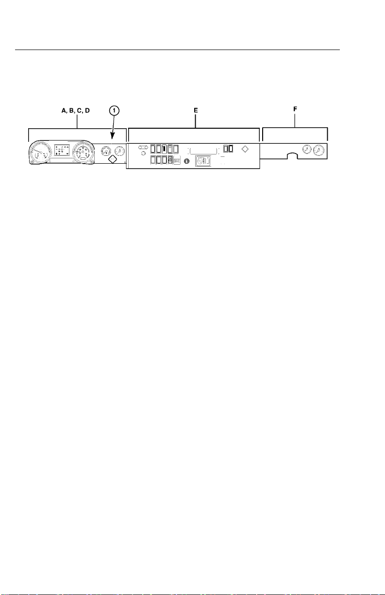
VehicleElectronicControlUnit(VECU)
TheV ehicleElectronicControlUnit(VECU)ismountedunderneathpanelDas
shownin.(CHU/CXU/GUmodelshown.)
TheVehicleElectronicControlUnit(VECU)isanelectroniccontrolmodulewhich
providesawidevarietyoffunctionsincluding:
•CruiseControl
•DiagnosticTroubleCode(DTC)Logging
•DifferentialLocking
•IdleShutdown
•MaintenanceInformation
•RoadSpeedLimiting
•SpeedControl
•TheftDeterrence
C0035358
VECULocation
Page 18

10V-MACCo-PilotOperator'sManual
VECU
C0035359
Page 19

V-MACCo-PilotOperator'sManual11
EngineControlModule(ECM)
TheEngineControlModule(ECM)islocatedtotheleftsideoftheengineandis
mountedtothefuelcooler,whichismountedbeneaththeinletmanifold(seegraph
reference).TheECMprovidesthefollowinginformationandfunctions:
•IntakeManifoldPressure(IMP)
•EngineCoolantLevel(ECL)
•EngineCoolantTemperature(ECT)
•CustomerRoadSpeedLimiting
•DiagnosticTroubleCode(DTC)Logging
•EngineOilPressure(EOP)
•EngineOilTemperature(EOT)
•EngineProtection
•EngineShutdown
•EngineSleepMode
•EngineSpeed(RPM)Control(basedoncommandsfromvehicleelectroniccontrol
unit(VECU))
•ExhaustAftertreatmentSystem(notallaftertreatmentfunctionsarecontrolled
bytheECM)
•FanControl
•FuelControl
•FuelT emperature
•TimingControl
•V ehicleLimitingSpeeds
EngineControlModule(ECM)Location
C0035356
Page 20

12V-MACCo-PilotOperator'sManual
EngineControlModule(ECM)(MACKMP7)
C0035360
Page 21

V-MACCo-PilotOperator'sManual13
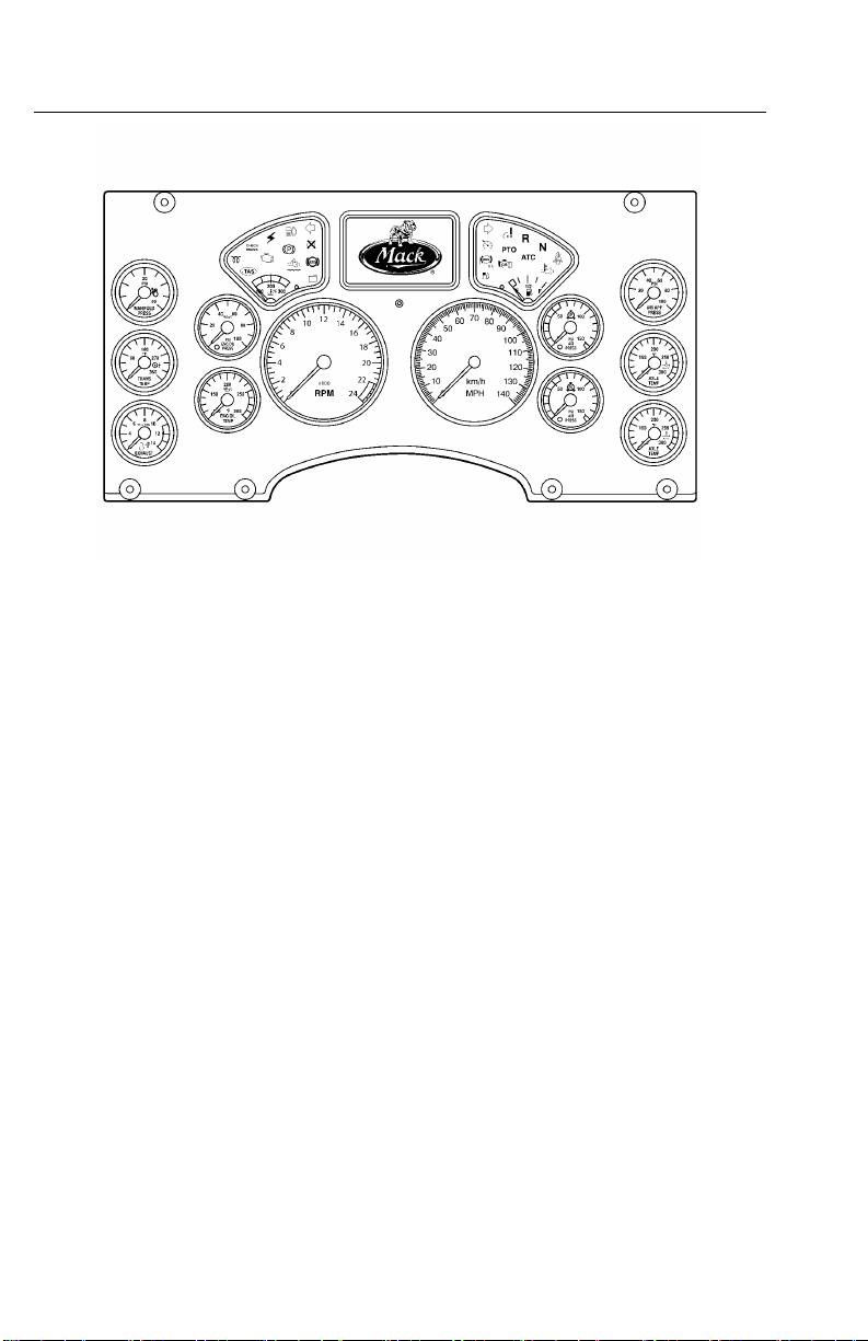
InstrumentCluster
Thevehiclemanagementandcontrol(V-MAC)IVInstrumentClusterisaone-piece
unitcomposedofgaugesandaninformationdisplay.TheInstrumentClusterreceives
informationfromtheVECUandEECUandthensendsinformationbacktotheVECU
andEECU.Informationisdisplayedwhenrequiredorrequestedviaastalkswitch
(Co-Pilot®only).
TheInstrumentClusterprovidesthefollowinginformation:
•AirBrakeApplication(Optional)
•AirFilterRestriction
•AirSuspensionPressure
•AxleOilTemperature(Optional)
•BrakeW ear
•CoolantTemperature(viaEECU)
•EngineandV ehicleSpeedDisplay
•ExhaustTemperature(Optional)
•FuelLevel
•HighBeamStatus
•HighExhaustSystemTemperature(HEST)
•IntegratedTemp-A-Start™(Optional)
•InteriorandOutsideTemperature
•OilPressure(viaEECU)
•PrimaryandSecondaryAirPressure
•SpeedometerandT achometerOutputs
•TransmissionOilTemperature(Optional)
•V ehicleDistance
Page 22
14V-MACCo-PilotOperator'sManual
InstrumentClusterModule
W3036315
Page 23

V-MACCo-PilotOperator'sManual15
GaugeDriverModule(GDM)
Thevehiclemanagementandcontrol(V-MAC)IV(GDM)isablackboxcontroller
usedintheLEUandMRUmodelchassis.TheGDMcontainsawarninglightbar,
anhourmeterlocatedinthetachometerandanodometerlocatedinthespeedometer.
Aseparatepushbuttonisavailabletotogglethroughdifferentfunctionssuchasto
retrievefaultcodesandviewtripinformation.
TheGDMprovidesthefollowinginformation:
•AirBrakeApplication
•AirCleanerRestriction
•AirSuspensionPressure
•AxleOilTemperature
•BrakeW ear
•EngineCoolantTemperature(ECT)(viaenginecontrolmodule(ECM))
•EngineandV ehicleSpeedDisplay
•EngineExhaustGasTemperature(EGT)
•FuelLevel
•HighBeamStatus
•HighEngineEGT
•EngineOilPressure(viaECM)
•PrimaryandSecondaryAirPressure
•SpeedometerandT achometerOutputs
•TransmissionOilT emperature
•V ehicleDistance
Page 24
16V-MACCo-PilotOperator'sManual
Figure6—LocationofGDM(PassengerSideAgainstBackofCab)
Figure7—LocationofGDM
C0035357
C0035431
Page 25

V-MACCo-PilotOperator'sManual17
INDICATORS,LIGHTSANDDASHBOARD
SWITCHES
CabandDashboardSwitches
Variousfunctionsofthevehiclemanagementandcontrol(V-MAC)IVsystemare
controlledbytheoperatorthroughswitcheslocatedonthedashboard(CHU/CXU/
GUmodelshowninFigure8).Thesefunctionsinclude:
•CruiseControl
•DaytimeRunningLightsOverrides(Optional)
•EngineBrakeOperation(Optional)
•EngineSpeed(RPM)Control
•ExhaustAftertreatmentSystem
•FanOverride(Optional)
•IdleShutdownOverrideOperation(Optional)
•IntegratedTemp-A-Start™(Optional)
•PTOOperation
Cruisecontrolandenginespeedcontrolfunctionsareexplainedinthismanualin
“CRUISEANDENGINESPEEDCONTROL”,page49.
Inadditiontotheseoperator-selectableswitches,additionalswitchesprovide
informationtotheV ehicleElectronicControlUnit(VECU)throughnormaldriving
activitiessuchasapplyingtheservicebrakes,parkingbrakesordisengagingthe
clutch.Thelocationoftheseswitchesisasfollows:
•Clutchpedalposition(CPP)switch
•Parkingbrakeswitch,locatedinlinewithintheparkingbrakecircuit
•Servicebrakeswitch,locatedinlinewithinthebrakesystem
Page 26

18V-MACCo-PilotOperator'sManual
Figure8—CabandDashboardSwitches(Example)
W2076077
Page 27
V-MACCo-PilotOperator'sManual19
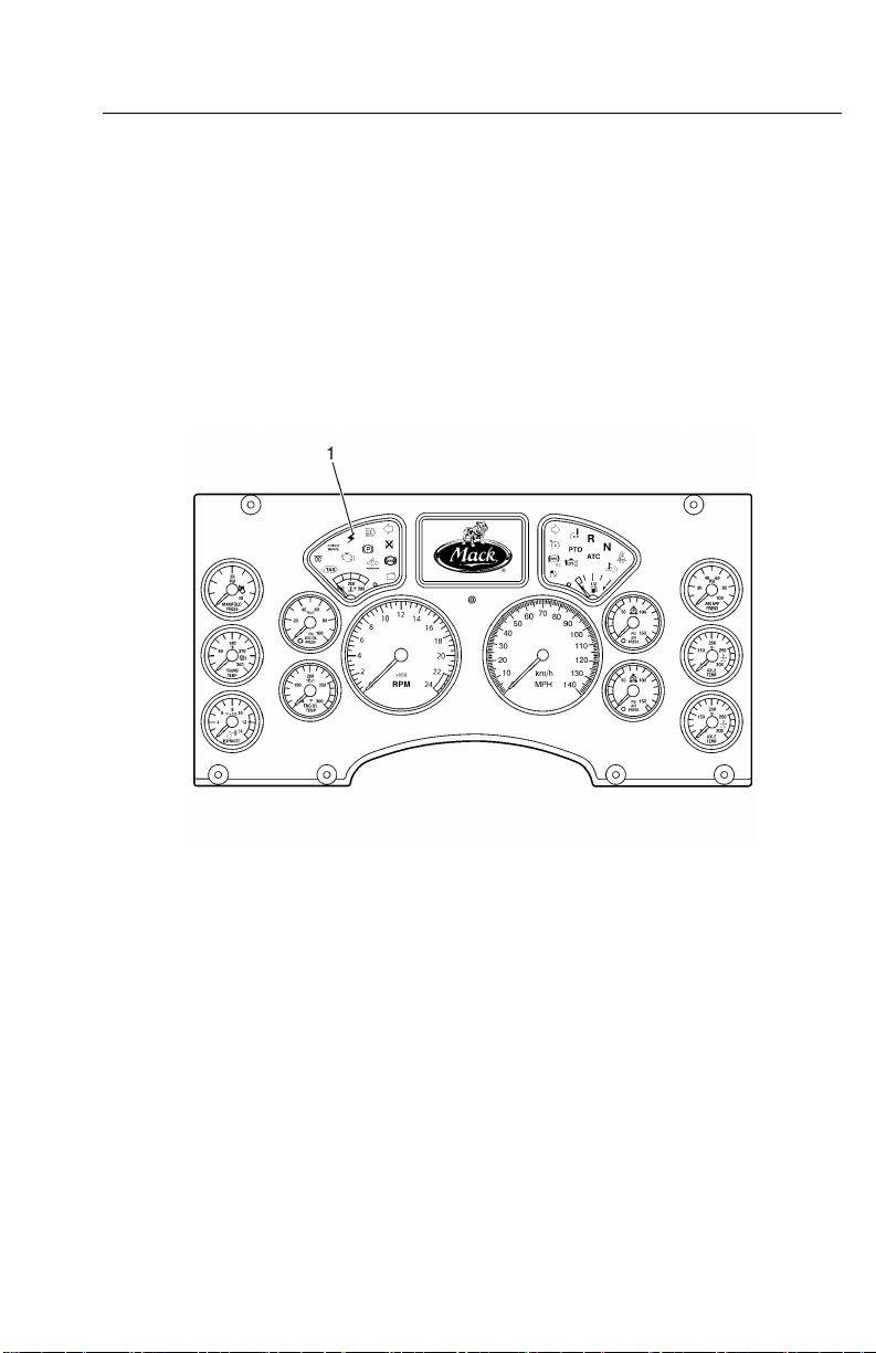
ElectronicMalfunctionIndicator
Theelectronicmalfunctionindicator,amberincolor,illuminatestoalertthedriverof
anelectricalproblemwiththevehiclemanagementandcontrol(V-MAC)IVsystem.
Thevehiclemanagementandcontrol(V-MAC)IVsystemdoesaself-testwhenthe
ignitionkeyisturnedtotheONposition.Theelectronicmalfunctionindicatorstays
onwhilethistestisbeingperformed(approximatelysixseconds).Aftertheself-test
iscompleted,theindicatorwillturnoffandremainoffunlessaproblemisdetected
byvehiclemanagementandcontrol(V-MAC)IV .Iftheindicatorturnsonwhilethe
vehicleisbeingdriven,vehiclemanagementandcontrol(V-MAC)IVhasdetecteda
problem.Inmostcircumstances,thevehiclewilloperateeventhoughtheindicator
ison;however,engineperformancemaybeaffected.
Figure9—ElectronicMalfunctionIndicator
W3036326
Page 28
20V-MACCo-PilotOperator'sManual
HighExhaustSystemTemperature(HEST)
Indicator
TheHighExhaustSystemTemperature(HEST)indicator,amberincolor,illuminates
toalertthedriverwhenengineexhaustgastemperatures(EGT)arehigh.TheHEST
indicatorwillalsoilluminateduringaaftertreatmentdieselparticulatelter(DPF)
parkedregenerationeventandwillturnoffaftertheregenerationiscompletedand
theexhaustEGThasreturnedtonormal.ForadditionalinformationabouttheHEST
indicator,pleasereferto
“AftertreatmentDPFSmartSwitch”,page24.
Figure10—HighExhaustSystemTemperature(HEST)Indicator
W3036496
Page 29
V-MACCo-PilotOperator'sManual21
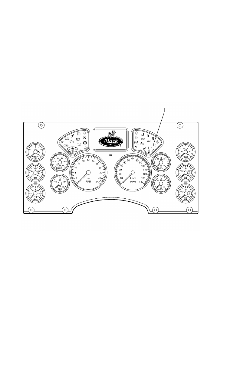
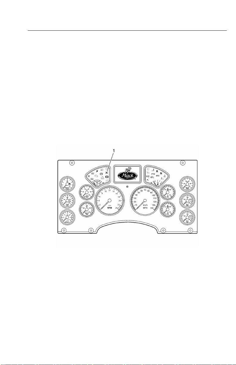
ShutdownWarningIndicator
TheShutdownWarningindicator,redincolor,illuminatesiftheenginecoolantlevel
(ECL)isbelowtheminimumlevelallowed,theengineoilpressure(EOL)isbelow
theminimumallowed,theenginecoolanttemperature(ECT)oraftertreatmentdiesel
particulatelter(DPF)sootleveltriggerareabovethemaximumallowed.Some
vehiclesalsohaveoptionalshutdownfunctionsavailablewhenthetransmission
temperatureorengineexhaustgastemperatures(EGT)areabovemaximumallowable
limits.
Duringashutdownevent,vehiclemanagementandcontrol(V-MAC)IValsoprovides
anaudiblealarm.Thealarmwillalsosoundandtheredshutdownindicatorwillturn
onwhenvehiclemanagementandcontrol(V-MAC)IVdetectsaproblemorexcessive
periodsofidling.Shuttingtheenginedowniswarranted.
Theshutdownwarningindicatorisusuallylocatedontheleft-handsideonthedash
cluster.
W3036501
1.EngineShutdownIndicator(RED)
Vehiclemanagementandcontrol(V-MAC)IVcanbeprogrammedtoactuallyshut
downtheengineifconditionswarrant(lowcoolant,lowEOL,highengineoil
temperature(EOT),highECT,highengineEGTorhighautomatictransmission
oiltemperatureifsoequipped).Shutdownismandatoryforcrankcasepressure
(CCP).Withthisoptionenabled,theenginewillautomaticallyshutdownwithin
approximately30secondsaftertheredSHUTDOWNindicatorturnsonandthealarm
activates(providedthevehicleisnotmovingabovetheroadspeedthreshold).
Page 30

22V-MACCo-PilotOperator'sManual
EngineDerate
Forsomeconditions(seetablebelow),anenginederatecanoccurrstandifa
conditionworsens,thenanengineshutdowncanoccur.
CONDITION
IntakeManifold
AirT emperature
Engine
Turbocharger
CompressorOutlet
Temperature
Engine
ExhaustGas
Recirculation
(EGR)
Temperature
Crankcase
Pressure(CCP)
HighEngine
Coolant
Temperature
(ECT)
ENGINEDERA TE
Deratestartsat120°C(248°F).
Fullderate(100%)occurswhen
temperatureisat140°C(284°F).
Deratestartsat245°C(473°F).
Torqueisderateddownto100%
at250°C(482°F).
Iftemperatureexceeds220°C
(428°F)formorethan20seconds
witha30secondperiod,derate
starts.
Iftemperaturereaches240°C
(464°F),a100%derateoccurs.
Ifachangeinpressure(difference
betweentheCCPandbarometric
pressure(BARO))risesabout5
kPa(0.725psi)withanoffset&0.5
kPa/s(0.07psi/s)andstaysover5
kPa(0.725psi)formorethan80%
ofthetimeduring1second,the
enginewillfullyderate(100%),be
forcedtoidle,andshutdown.
Deratestartsat106.75°C
(224.15°F)andrampsdown
to12%derate.Torqueiskept
constantuntilthetemperature
reaches107.25°C(225.05°F).
Deratestartsagainat107.4°C
(225.32°F)andrampsdownto
32%derate.
Torqueisderateddownto100%at
108.4°C(227.12°F).
ENGINE
SHUTDOWN
Noengine
shutdown.
Noengine
shutdown.
Noengine
shutdown.
Engineshutdown.Redengine
INDI-
CATOR
LIGHTS
Nowarning
indicators.
Nowarning
indicators.
Nowarning
indicators.
shutdown
indicator.
Amber
malfunction
indicatorlights
at107.2°C
(224.96°F).
Redengine
shutdown
indicatorlights
at108°C
(226.4°F).
Engine
shutdownif
temperature
risesto109°C
(228.2°F).
Page 31

V-MACCo-PilotOperator'sManual23
CONDITION
EngineOil
Temperature
(EOT)
Afteretreatment
Diesel
Particulate
ENGINEDERA TE
Deratestartswith10%derate
at129°C(264.2°F)ormore
for75%ofa4secondperiod.
At132°C(269.6°F)a100%
derateoccurs.
ForCatalyzedA TS:Deratestarts
whensoottriggerratiois1.4and
continuesdownto20%derate.
ENGINE
SHUTDOWN
Engine
shutdownif
temperature
risesto135°C
(275°F).
Filter(DPF)
Soot
ForCatalyzedA TS:Torqueis
rampeddownto80%deratewhen
soottriggerratiois1.7.
ForNon-CatalyzedA TS:Derate
startswhensoottriggerratiois
1.15.
ForNon-CatalyzedA TS:T orque
isrampeddownto40%derate
whensoottriggerratiois1.20.Full
derateoccurswhensoottrigger
ratiois1.22.
Engine
Turbocharger
Wheel
*-ATS(AftertreatmentSystem).Pleaserefertopage26forinformationontheExhaust
AftertreatmentSystem.
For11and13literengines,derate
startsat129,500RPM.Fullderate
(100%)occursat130,500RPM.
For16literengines,deratestartsat
102,500RPM.Fullderate(100%)
occursat103,500RPM.
Noengine
shutdown.
INDI-
CATOR
LIGHTS
Amber
malfunction
indicator
lightswhen
temperature
isat129°C
(264.2°F).
Redengine
shutdown
indicator
lightswhen
temperature
isat131°C
(267.8°F).
Amber
malfunction
indicatorlights
upwhensoot
triggerratiois
1.4.
Redengine
shutdown
indicatorlights
upwhensoot
triggerratiois
1.7.
Amber
malfunction
indicatorlights
upwhensoot
triggerratiois
1.15.
Redengine
shutdown
indicatorlights
upwhensoot
triggerratiois
at1.22.
Nowarning
indicators.
Page 32

24V-MACCo-PilotOperator'sManual
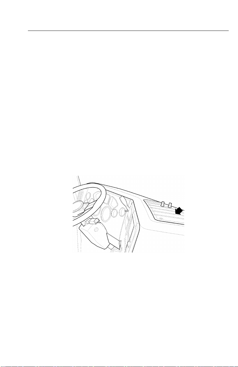
IdleShutdownOverrideSwitch
Theidleshutdownoverrideswitchpermitstheoperatortooverrideanidleshutdown.
Figure13—PanelIdleShutdownOverrideSwitch
W2076075
AftertreatmentDPFSmartSwitch
Figure14—AftertreatmentDPFSmartSwitch
W2076076
Page 33

V-MACCo-PilotOperator'sManual25
Theaftertreatmentdieselparticulatelter(DPF)smartswitchisathree-position
rockerswitchwheretheUPpositionismomentary,theMIDDLEpositionisneutral
(standbymode)andtheDOWNpositionislocked.Theswitchallowstheoperatorto
interfacewiththevehicle'sexhaustaftertreatmentsystem.
Theswitchhasseveralfunctionsasoutlinedbelow.
•IndicatesthataanaftertreatmentDPFregenerationisneededorhasstartedwhen
theiconsontheswitchareilluminated.
•IndicatesthataregenerationhasbeenstoppedwhentheDOWNpositionofthe
switchispressed,lockedandilluminated.
•StopsaregenerationeventwhentheDOWNpositionoftheswitchispressed,
lockedandilluminated.
•StartsanaftertreatmentDPFmanualregenerationeventwhentheswitchis
momentarilypressedtotheUPposition.
•Goesintostandbymodeandwaitsforregenerationwhentheswitchisinthe
MIDDLEposition.
C0035425
Figure15—DPFSmartSwitch
ForadditionalinformationontheAftertreatmentDPFSmartSwitchandRegeneration,
pleasereferto
“EXHAUSTAFTERTREA TMENTSYSTEM”,page26.
Page 34

26V-MACCo-PilotOperator'sManual
EXHAUSTAFTERTREATMENTSYSTEM
AftertreatmentDPFRegeneration
ADPFintheexhaustisusedtomeetenvironmentalprotectionagency(EPA)
requirementstohelpreducesootandparticulateemissionsintotheatmosphere.The
particulatesaretypicallyremovedbycollectinginaDPF,withcontinuousorperiodic
regenerationofthelter.Theelectricalandexhaustaftertreatmentsystemsetup
ofthevehiclewilldeterminewhenregenerationisrequired.Whenregenerationis
needed,theiconsontheDPFSmartswitchwilllightupmomentarilytonotifythe
driverandthenshutoffduringregeneration.Thehighexhaustsystemtemperature
(HEST)indicatorwilllightupontheinstrumentclustertowarnofhighexhaust
temperatures(whenvehiclespeedislessthan8km/h[5mi/h]orwhenparked).
Dependingonthevehicle'saftertreatmentsetup,regenerationcanbeperformedwhile
movingorwhenthevehicleisparked.Belowisgeneralinformationabouttheexhaust
aftertreatmentsystems.
Fornon-catalyzedexhaustaftertreatmentsystems
•V ehiclespeedmustbeatleast8km/h(5mi/h)inorderforthepassiveregeneration
tostart.
•IconsontheDPFSmartswitchwillmomentarilylightupandthenshutoffduring
theregeneration.
•HESTindicatoroninstrumentclusterwilllightuptowarnofhighexhaust
temperatureswhenvehiclespeedis8km/h(5mi/h)orless.HESTindicatorwill
shutoffwhenvehiclespeedis16km/h(10mi/h)orhigher.
•Enginespeed(RPM)willremainatidleduringregeneration(forparked
regeneration).
Forcatalyzedexhaustaftertreatmentsystems
•V ehiclespeedmustbeatleast40km/h(25mi/h)inorderforthepassive
regenerationtostart.
•Enginecoolanttemperature(ECT)is35°C(95°F)orhigher.
•IconsontheDPFSmartswitchwillmomentarilylightupandthenshutoffduring
theregeneration.
•HESTindicatoroninstrumentclusterwilllightuptowarnofhighexhaust
temperatureswhenvehiclespeedis8km/h(5mi/h)orless.HESTindicatorwill
shutoffwhenvehiclespeedis16km/h(10mi/h)orhigher.
•Enginespeedwillrampuptoaround1,100RPMduringregeneration(forparked
regeneration).
Page 35

V-MACCo-PilotOperator'sManual27
AftertreatmentDPFPassiveRegeneration
Aftertreatmentdieselparticulatelter(DPF)passiveregenerationcanbeautomatic
(nooperatorinputneededtostartregeneration)ormanual(operatorinputneededto
startregeneration).Theoperatorisnotiedthataregenerationisneededwhenthe
iconsontheDPFSmartswitchilluminate.
PleaserefertotheinstructionsbelowonhowtousetheDPFSmartswitchforpassive
regenerations.
Passive(Automatic)Regeneration
1WhentheiconsontheDPFSmartswitchlightup,maintainvehiclespeed.
2Duringregeneration,theiconsontheswitchwillshutoff.
3Regenerationwilltakebetween20and30minutestocomplete.
4Iftheregenerationprocessneedstobestoppedandperformedatalatertime,please
referto“AftertreatmentDPFInhibit/StopRegeneration”,page29forinformation.
Moving(Manual)Regeneration(IfAvailable)
1WhentheiconsontheDPFSmartswitchlightup,maintainvehiclespeedand
pressandholdthetoppartoftheswitchmomentarily.
2Duringregeneration,theiconsontheswitchwillshutoff.
3Regenerationwilltakebetween20and30minutestocomplete.
4Iftheregenerationprocessneedstobestoppedandperformedatalatertime,please
“AftertreatmentDPFInhibit/StopRegeneration”,page29forinformation.
referto
Note:Dependingonthevehicle'sconguration,itmaybepossibletoperforma
parkedregenerationifnecessary.
Page 36

28V-MACCo-PilotOperator'sManual
AftertreatmentDPFParkedRegeneration
Aftertreatmentdieselparticulatelter(DPF)parkedregenerationallowstheoperator
tostartand/orstoptheregenerationmanuallywhenthevehicleisparked.Theoperator
isnotiedthataregenerationisneededwhentheiconsontheDPFSmartswitch
illuminate.Theoperatorshouldperformtheregenerationassoonaspossible.
PleaserefertotheinstructionsbelowonhowtousetheDPFSmartswitchforparked
regenerations.
1Movethevehicletoasafelocation,applytheparkbrakeandallowtheengineto
idle.
Note:Whenaregenerationisinprocess,theengineexhaustgastemperature
(EGT)willbeelevated.DONOTparkthevehiclewiththeexhaustoutletunder
lowhangingoverheadammableobjectssuchastrees,awnings,etc.,thatcouldbe
damagedbyelevatedexhausttemperatures.DONOTattempttoregenerateinside
agarageorenclosedareaifthetailpipeisattachedtoanexhaustventilationsystem
asthehosematerialmaynotberatedforthehightemperature.
2PressandholdthetoppartoftheDPFSmartswitchmomentarilytoinitiatethe
regeneration.
3Duringregeneration,theiconsontheswitchwillshutoff.Thehighexhaustsystem
temperature(HEST)indicatorontheinstrumentclusterwilllightuptonotify
ofhighexhausttemperatures.
4Forcatalyzedexhaustaftertreatmentsystems,theenginespeed(RPM)willramp
uptoaround1,100RPM.Fornon-catalyzedexhaustaftertreatmentsystems,the
enginewillcontinuetoidleduringtheregeneration.
5Regenerationwilltakebetween20and30minutestocomplete.
6Afterregenerationhascompletedandtheexhausttemperaturehasreturnedto
normal,theHESTindicatorwillshutoff.
7Iftheregenerationprocessneedstobestoppedandperformedatalatertime,please
referto
“AftertreatmentDPFInhibit/StopRegeneration”,page29forinformation.
CAUTION
Failuretoperformanaftertreatment
DPFregenerationinatimelymanner
afternoticationmayresultinengine
derate,cloggedordamagedDPF,and
engineshutdown.
Page 37

V-MACCo-PilotOperator'sManual29
AftertreatmentDPFInhibit/StopRegeneration
Aftertreatmentdieselparticulatelter(DPF)regeneration,whetherthemovingor
parkedvariety,canbestoppedifthevehicleisequippedwithaDPFSmartswitch
(referto
regenerationshouldbestoppedonlywhennecessary.T ostoparegenerationthatisin
progress,presstheDPFSmartswitchtotheDOWNposition.Theswitchwilllock
intotheDOWNposition,andtheicononthebottomoftheswitchwillbeilluminated
toindicateregenerationhasbeenstopped.
“AftertreatmentDPFSmartSwitch”,page24formoreinformation).A
C0035426
Figure16—Inhibit/StopRegeneration
CAUTION
WhentheDPFSmartSwitchispressed
totheDOWNposition,theswitch
willremainlockedinthisposition
andpreventaftertreatmentDPF
regenerationfromoccurring.Therefore,
itisimportanttopresstheswitchback
tothemiddlepositionandtoreturnit
tostandbymodewhensafetodoso.
Failuretosettheswitchbacktothe
MIDDLEpositionmayresultinengine
derate,acloggedAftertreatmentDiesel
ParticulateFilter(DPF),damagetothe
lterandengineshutdown.
Iftheoperatorstopsorinhibitsregenerationrepeatedly,theDPFwillbegintoclog
withsootandengineexhaustgaspressurewillincrease.Eventuallytheenginewill
derateandultimatelyshutdown.Belowisaquicklookatthetypeofregenerations,
conditionsoftheexhaustaftertreatmentsystemandtheactiontobetaken.
CAUTION
FailuretoperformaaftertreatmentDPF
regenerationinatimelymannermay
resultinenginederate,acloggedor
damagedDPF,damagetothelterand
engineshutdown.
Page 38

AFTERTREATMENTDPFPASSIVEREGENERA TION(AUTOMATIC)
30V-MACCo-PilotOperator'sManual
SootLoad
Level
Indicators
Level1Level2
(Solid)
(Flashing)(Flashing)
Level3Level4
(Amber)
(Flashing)
(Red)
Aftertreatment
System
Condition
Regenerationneeded.
DPFisbecomingfull.
Regenerationis
required.
DPFisfull.
AftertreatmentSystemServiceRequired.
EngineDerateActive.
EnginePerformanceislimited.
SootLevelHigh.
DPFisoverfull.
AftertreatmentSystemServiceRequired.
EngineDerateActive.
SootLevelisCriticallyHigh.
DPFmaybeoveritsmaximumcapacity .
Enginemayshutdown.
Page 39

SootLoad
Level
ActiontoTakeContinuetodriveor
Level1Level2
parkthevehiclein
asafelocationaway
fromoverhanging
objects(parkbrake
applied)andallow
theenginetorunand
theregenerationto
complete.
AFTERTREATMENTSYSTEMP ASSIVEREGENERATION(AUTOMATIC)
Level3Level4
Continuetodriveor
parkthevehiclein
asafelocationaway
fromoverhanging
objects(parkbrake
applied)andallow
theenginetorunand
theregenerationto
complete.
Performaparkedmanualregeneration
IMMEDIATEL Ytoavoidfurtherengine
derateanddamagetotheDPF.
Note:Failuretoperformthe
regenerationwilltakethe
AftertreatmentSystemtoLevel4.
Aseriousengineproblemhasoccurred.
Seekserviceimmediately.
V-MACCo-PilotOperator'sManual31
Note:Parkedregenerationisno
longerpossiblefortheoperator.
Note:Failure
toperformthe
regeneration
willtakethe
Aftertreatment
SystemtoLevel2.
Regeneration
Condition
Ifpassiveregenerationisallowedtorun,thefollowingnormalprocessesmaybeobserved.
Note:Failure
toperformthe
regeneration
willtakethe
Aftertreatment
SystemtoLevel3.
•HESTindicatorwillturnoffifvehiclespeedis16km/h(10mi/h)orhigher.
•DPFSmartswitchindicatorwillshutoffduringtheregeneration.
•Regenerationtakesbetween20and30minutestocomplete.
Page 40

32V-MACCo-PilotOperator'sManual
AFTERTREATMENTSYSTEMPASSIVEREGENERATION(MANUAL)(IFA V AILABLE)
SootLoad
Level
Indicators
Level1Level2
(Solid)
(Flashing)(Flashing)
Level3Level4
(Amber)
(Flashing)
(Red)
Aftertreatment
System
Condition
Regenerationneeded.
DPFisbecomingfull.
Regenerationis
required.
DPFisfull.
AftertreatmentSystemServiceRequired.
EngineDerateActive.
EnginePerformanceislimited.
SootLevelHigh.
DPFisoverfull.
AftertreatmentSystemServiceRequired.
EngineDerateActive.
SootLevelisCriticallyHigh.
DPFmaybeoveritsmaximumcapacity .
Enginemayshutdown.
Page 41

AFTERTREATMENTSYSTEMPASSIVEREGENERATION(MANUAL)(IFA V AILABLE)
SootLoad
Level
ActiontoTakeContinuetodriveand
Level1Level2
pressandholdthe
topoftheDPFSmart
switchmomentarily.
Alternatively,park
thevehicleinasafe
locationawayfrom
overhangingobjects
(parkbrakeapplied).
Pressandholdthe
topoftheDPFSmart
switchmomentarily.
Note:Failure
toperformthe
regeneration
willtakethe
Aftertreatment
SystemtoLevel2.
Regeneration
Condition
Ifmovingmanualregenerationisallowedtorun,thefollowingnormalprocessesmaybeobserved.
•HESTindicatorwillturnoffifvehiclespeedis16km/h(10mi/h)orhigher.
•DPFSmartswitchindicatorwillshutoffduringtheregeneration.
•Regenerationtakesbetween20and30minutestocomplete.
Continuetodriveor
parkthevehiclein
asafelocationaway
fromoverhanging
objects(parkbrake
applied)andallow
theenginetorunand
theregenerationto
complete.
Note:Failure
toperformthe
regeneration
willtakethe
Aftertreatment
SystemtoLevel3.
Level3Level4
Performaparkedmanualregeneration
IMMEDIATEL Ytoavoidfurtherengine
derateanddamagetotheDPF.
Note:Failuretoperformthe
regenerationwilltakethe
AftertreatmentSystemtoLevel4.
Aseriousengineproblemhasoccurred.
Seekserviceimmediately.
V-MACCo-PilotOperator'sManual33
Note:Parkedregenerationisno
longerpossiblefortheoperator.
Page 42

34V-MACCo-PilotOperator'sManual
AFTERTREATMENTSYSTEMPARKEDREGENERA TION(MANUAL)
SootLoad
Level
Indicators
Level1Level2
(Solid)
(Flashing)(Flashing)
Level3Level4
(Amber)
(Flashing)
(Red)
Aftertreatment
System
Condition
Regenerationneeded.
AftertreatmentDiesel
ParticulateFilter
(DPF)isbecoming
full.
Regenerationis
required.
DPFisfull.
AftertreatmentSystemServiceRequired.
EngineDerateActive.
EnginePerformanceislimited.
SootLevelHigh.
DPFisoverfull.
AftertreatmentSystemServiceRequired.
EngineDerateActive.
SootLevelisCriticallyHigh.
DPFmaybeoveritsmaximumcapacity .
Enginemayshutdown.
Page 43

AFTERTREATMENTSYSTEMPARKEDREGENERA TION(MANUAL)
SootLoad
Level
ActiontoT akeParkthevehiclein
Level1Level2
asafelocationaway
fromoverhanging
objects(parkbrake
applied).
Pressandholdthe
topoftheDPFSmart
switchmomentarily.
AllowtheDPF
regenerationprocess
tocomplete.
Parkthevehiclein
asafelocationaway
fromoverhanging
objects(parkbrake
applied).
Pressandholdthe
topoftheDPFSmart
switchmomentarily.
AllowtheDPF
regenerationprocessto
complete.
Level3Level4
Performaparkedaftertreatmentdiesel
particulatelter(DPF)regeneration
IMMEDIATEL Ytoavoidfurtherengine
derateanddamagetotheDPF.
Note:Failuretoperformthe
DPFregenerationwilltakethe
AftertreatmentSystemtoLevel4.
Aseriousengineproblemhasoccurred.
Seekserviceimmediately.
V-MACCo-PilotOperator'sManual35
Note:ParkedDPFregenerationis
nolongerpossiblefortheoperator.
Note:Failure
toperformthe
regeneration
willtakethe
Aftertreatment
SystemtoLevel2.
Note:Failure
toperformthe
regeneration
willtakethe
Aftertreatment
SystemtoLevel3.
Page 44

AFTERTREATMENTSYSTEMPARKEDREGENERA TION(MANUAL)
Aftertreatment
dieselparticulate
lter(DPF)
regeneration
Condition
Ifparkedmanualaftertreatmentdieselparticulatelter(DPF)regenerationisallowedtorun,thefollowingnormalprocessesmaybe
observed.
•Enginespeed(RPM)willrampuptoaround1,100RPMandstaythereuntiltheDPFregenerationprocessis
complete.**
•HESTindicatorwillturnontowarnofhighengineexhaustgastemperature(EGTandwillstayonduring
aftertreatmentdieselparticulatelter(DPF)regeneration.
•DPFSmartswitchindicatorwillshutoffduringtheaftertreatmentdieselparticulatelter(DPF)regeneration.
•Aftertreatmentdieselparticulatelter(DPF)regenerationtakesbetween20and30minutestocomplete.
•HESTindicatorwillturnoffafteraftertreatmentdieselparticulatelter(DPF)regenerationiscompleteand
exhausttemperatureshavereturnedtonormal.
**Enginespeedrampupconditionforcatalyzedexhaustaftertreatmentsystems
36V-MACCo-PilotOperator'sManual
Page 45

V-MACCo-PilotOperator'sManual37
AftertreatmentDriverWarningandInducement
AftertreatmentDEFTankLevel-DriverWarning
&Inducement
AftertreatmentDEFtanksaresizedtohavenolessthantwotimesthedieselfuel
tankmileageoronehourrange.
ThevehicleinstrumentclusterhasanaftertreatmentDEFtanklevelgauge.
Note:RepeatedactsoftamperingwillresultinmoresevereInducement.
TriggersAftertreatmentDEF
TankLowLevel
Indicator
100%to12%Aftertreatment
DEFTankLevelGauge
<=12%AftertreatmentDEF
TankLevelGauge
0%AftertreatmentDEFTank
LevelGauge(~1%DEF
Remaining)
NoneNone
Solidindicator
Blinkingindicator
DriverInformation
DisplayScreen
DEFTankLevelLow
RellDEFSoonto
PreventEngineDerate
W2029416
DEFTankEmpty
RellDEFtoavoid5
MphLimit
EngineinDerate
W2029415
Page 46

38V-MACCo-PilotOperator'sManual
TriggersAftertreatmentDEF
TankLowLevel
Indicator
DEFtankemptyandrefueling
eventwithparkingbrake
applied
VehicleStationaryfor20
minutesorEnginere-start
(KeyOFF,KeyON)
DriverInformation
DisplayScreen
RellDEFTank
VehicleSpeedLimited
to5Mph
W2029415
RellDEFTank
VehicleSpeedLimited
to5Mph
W2029415
Page 47

V-MACCo-PilotOperator'sManual39
AftertreatmentDEFQuality-DriverWarning&
Inducement
TriggersAftertreatmentDEF
QualityIndicator
GoodDEFQuality
NoneNone
PoorDEFQualityDTC
InitialDetected
PoorDEFQualityDTC
InitialDetected+1hours
PoorDEFQualityDTC
InitialDetected+4hours
DriverInformation
DisplayScreen
SCRPerformanceLow
EnginewillDeratein
___mins
W3
031
623
SCRPerformanceLow
EngineInDerate
5MphLimitin___
W3
031
623
mins
Note:OncethisDEF
Qualityfaultoccurs
theDIDtimerdisplays.
Thetimerdisplaysthe
minutesavailablebefore
the5mphderateoccurs.
Thetimercanbecleared
usingtheEscape(ESC)
buttononthestalk
switchcontrollever.
Whenthevehicleis
restartedaftershutdown
theremainingminutes
beforederateoccurswill
reappear.Foradditional
DIDinformationreferto
theDriverInformation
DisplayManual.
SCRPerformanceLow
Repairneeded
5Mphlimitnext
W3
031
623
VehicleStop
Page 48

40V-MACCo-PilotOperator'sManual
TriggersAftertreatmentDEF
QualityIndicator
RefuelingEventwithParking
BrakeON
VehicleStationaryfor20
minutesorEnginere-start
(KeyOFF,KeyON)
TemporaryExitfrom8Km/h
(5mph)Inducement
IgnitionKeyCycle
DriverInformation
DisplayScreen
SCRPerformanceLow
ServiceSCRSystem
VehSpeedLimitedto5
W3
031
623
Mph
SCRPerformanceLow
ServiceSCRSystem
VehSpeedLimitedto5
W3
031
623
Mph
SCRPerformance
Evaluation
ContinueDriving.5
W3
031
623
MphLimit
TemporarilyRemoved
SCRPerformanceLow
ServiceSCRSystem
VehSpeedLimitedto5
W3
031
623
Mph
Firststartafterthekeycycle
(onetimeonly)
SCRPerformance
Evaluation
ContinueDriving.5
W3
031
623
MphLimit
TemporarilyRemoved
ExitconditionsforDEFQuality"8Km/h(5mph)roadspeedlimit"Inducement:
Next1EngineStarts:Returnto25%torquereductionuntilthereisaproperDEF
qualityevaluation.IfpoorDEFqualityisdetectedduringthenextmonitoringcycle
then8Km/h(5mph)isresumedafterthevehicleisstationaryfor20minutes.After
oneenginestarthasbeenexhaustedthenaTechT oolisrequiredtoexitthe8Km/h(5
mph)roadspeedlimit.
WithTechToolDTCClearing:Invoke25%torquereductionuntilthereisaproper
DEFqualityevaluation.IfpoorDEFQualityisdetectedduringthenextmonitoring
cyclethen8Km/h(5mph)isresumedafterthevehicleisstationaryfor20minutes.
Page 49

V-MACCo-PilotOperator'sManual41
AftertreatmentTampering-DriverWarning&
Inducement
WhentheSCRtamperingfaultisactiveforoneormorehoursanewDriver
InformationDisplayscreenappears.ThetextchangesfortheDriverInformation
Display(DID)screenassociatedwiththisfaultarelistedinthetablebelow.
TriggersAftertreatment
NoFault
TamperingFaultDetected
Note:Forexamplesof
thevariousSCRsensor
tamperingtypesrefertothe
“SCRSensorDisconnected
TamperingT ype”table
below.
TamperingIndicator
NoneNone
W3031200
DriverInformation
DisplayScreen
SCRSystemFault
EnginewillDeratein
___mins
Page 50

42V-MACCo-PilotOperator'sManual
TriggersAftertreatment
DrivingwithActiveFaultfor
+1hrs
DrivingwithActiveFaultfor
+4hrs
TamperingIndicator
DriverInformation
DisplayScreen
SCRSystemFault
EngineInDerate
5MphLimitin___
W3031200
mins
Note:OncethisSCR
tamperingfaultoccurs
theDIDtimerdisplays.
Thetimerdisplaysthe
minutesavailablebefore
the5mphderateoccurs.
Thetimercanbecleared
usingtheEscape(ESC)
buttononthestalk
switchcontrollever.
Whenthevehicleis
restartedaftershutdown
theremainingminutes
beforederateoccurswill
reappear.
SCRSystemFault
Repairneeded
5Mphlimitnext
W3031200
VehicleStop
1RefuelingEvent(>15%
fuellevelincrease)with
stationarybrake
2Vehiclestationaryfor20
minutes(vehiclespeed<
1.6Km/h(1mph)
3IgnitionKeyCycle
SCRSystemFault
VehSpeedLimitedto5
Mph
W3031200
Page 51

V-MACCo-PilotOperator'sManual43
SCRSensorDisconnectedT amperingType
ExhaustTemperatureSensorsDisconnected
AftertreatmentControlModule(ACM)Disconnected
AftertreatmentNOxSensorDisconnected
AftertreatmentNOxSensorDisconnected
DEFPumpDisconnected
DEFDosingV alveDisconnected
DEFT ankLevelSensorDisconnected
DEFSupplyLinetoDEFPumpDisconnected
DEFReturnLineBlockedorPlugged
MisllingDieselorAftertreatmentDEFTanks
AlthoughdieselfuelandAftertreatmentDEFcapsareclearlylabeledandllernecks
andnozzlesaredifferentaccidentscanhappen.
Contaminationofuidsby-misllingofdieselorDEFinthewrongtankmayresult
invehiclemalfunction.
ResultsofmisllingDEFinDieselTank
•Enginemayrunpoorlyornotatall
•Injectorsmaybedamaged
•ExhaustsystemcorrosionmayoccurbetweenturbochargerandAftertreatmentDPF
•OnBoardDiagnostic(OBD)DiagnosticTroubleCodes(DTC)
•Costlyrepairs
ResultsofmisllingdieselinAftertreatmentDEFTank
•AftertreatmentSCRsystemmaybedamagedbyDiesel
•SCRCatalystmaybedamagedbydiesel(chemicaldamage)
•Emissionsmaybenon-compliant
•OnBoardDiagnostic(OBD)DiagnosticTroubleCodes(DTC)
•Costlyrepairs
Page 52

44V-MACCo-PilotOperator'sManual
AftertreatmentDPFRegenerationandPTO
Operation
Foraftertreatmentdieselparticulatelter(DPF)regenerationtooccur,enoughheat
mustbegeneratedinthedieseloxidationcatalyst(DOC).Heatisgeneratedby
increasingenginespeed(RPM)toaround1,100RPMonvehicleswithacatalyzed
aftertratmentsystem.ForvehiclesthatoperateapowertakeoffandhaveaDPF ,the
PTOmusthaveamaximumratedspeedabovetheminimumRPMlistedinthetables
belowsothataftertreatmentdieselparticulatelter(DPF)regeneration(whether
automaticormanual)canoccurwhencommanded.
Figure18–MinimumEngineSpeedsforMP7withCatDPF
C0035438
C0035439
Figure19—MinimumEngineSpeedsforMP8withCatDPF
C0035442
Figure20—MinimumEngineSpeedsforMP10withCatDPF
Note:ForvehiclesequippedwithacatalyzedDPF,thePTOmustbeactivatedbya
switchthatprovidesbothengagementandspeedinformationtothevehicleelectronic
controlunit(VECU)whenthePTOisengaged.Thevehicleoperatormustuseengine
speedcontroltosetenginespeedwhenthePTOisinoperation.
Page 53

V-MACCo-PilotOperator'sManual45
Figure21—MinimumEngineSpeedsforMP7withCatDPFVehicle21 173561
Note:Beginningwith21198958andnewersoftware,theonlyrequirementfor
aftertreatmentdieselparticulatelter(DPF)regenerationonvehiclesequippedwith
anMP7withnon-catalyzedDPFandPTOisnolessthan650RPM.Altitudeand
temperaturearenolongerfactorsforaftertreatmentdieselparticulatelter(DPF)
regenerationandPTOoperation.
AftertreatmentDPFRegenerationandPTO
Engaged
Ifaftertreatmentdieselparticulatelter(DPF)manualstationaryregenerationswith
thepowertakeoff(PTO)engagedarerequired,thevehiclemustbeconguredas
follows:
•SetparameterEnableManualRegenDuringPTO(JAC)to“Y es”or“On”
usingVCADS.Thisparametercanbefoundinthe“Misc.V ehicleSettings”
sectioninParameterProgramming.(AconnectiontoCentralSystemsisrequired
tosetparameterIDJAC.)
•InitiateManualStationaryRegenerationusingtheDPFsmartswitch.
•Ensuretheelectronichandthrottle(enginespeedcontrol)isactive.The
enginespeed(RPM)mustbesettogreaterthantheminimumspeedslistedin
“AftertreatmentDPFRegenerationandPTOOperation”,page44.
C0035440
Ifthevehicleisnotconguredaslistedabove,manualstationaryaftertreatmentdiesel
particulatelter(DPF)regenerationwiththePTOengagedwillnotoccur.When
aftertreatmentdieselparticulatelter(DPF)regenerationdoesnot
willbecomesoot-loaded,resultinginenginederateandeventualengineshutdown.
takeplace,theDPF
Page 54

46V-MACCo-PilotOperator'sManual
AftertreatmentSystemConditioning(PeriodicHeat
Mode)
Duringperiodsofextendedidling(typically8ormorehours),theaftertreatment
systemwillaccumulateunburnedhydrocarbonsthatarereleasedfromadieselengine.
Accumulationofthesehydrocarbonscanoxidizeintheaftertreatmentsystemandcan
causedamagingtemperaturespikesandpotentialhardwarefailuresuponresumed
drivingorduringaftertreatmentDPFstationaryregenerationevents.
Extendedidlingperiodsshouldbelimitedtolessthan24hoursinordertoprotect
theaftertreatmentsystem.However,forcustomerswhoidletheirvehiclespastthe
24hourlimit,aperiodicheatmode(knownasAftertreatmentSystemConditioning),
wasdevelopedforthecatalyzedaftertreatmentsystem.
Note:AftertreatmentsystemconditioningisNOTavailableonvehiclesequippedwith
anon-catalyzedaftertreatmentsystem.
AftertreatmentsystemconditioningpurgestheDPFofaccumulatedhydrocarbons
typicallyevery8to15hoursofextendedidlingtime.Theprocessisaccomplishedby
elevatingexhausttemperaturestoapproximately100to200°Cfor5to8minutes,and
byrampinguptheenginebetween1050and1400RPM(dependentonenginemodel,
ambientairtemperature(AA T)andaltitude).
Whenaftertreatmentsystemconditioningisactiveandtheenginerampsup,a
messagewillappearontheCo-Pilot®Displayindicatingthatthecycleisactive
andnodriverinputisnecessary.Whenthecycleiscompleted,theenginewillramp
downtonormalidlingspeed.
Note:Itisrecommendedthattheaftertreatmentsystemconditioningcyclenotbe
interruptedwhileinprogress.Ifpossible,donotsteponthethrottle,releasethepark
brakeormoveoutofneutraluntilthecycleiscompleted(from5to8minutes).
Page 55

V-MACCo-PilotOperator'sManual47
AftertreatmentSystemConditioningandPTO
Operation
Whentheaftertreatmentsystemconditioningcyclebecomesactiveandapower
takeoff(PTO)isengaged,theenginespeed(RPM)shouldremainatthePTOset
speed,providedtheRPMandPTOengageinputsareenabled.ThePTOmustbe
activatedbyaswitchtoprovidePTOengagementandspeedinputtothevehicle
electroniccontrolunit(VECU)(sothattheenginecontrolmodule(ECM)knows
thestatusofthePTO).IftheseinputsarenotenabledandthePTOisengaged,
aftertreatmentsystemconditioningwillincreaseRPMwhencommanded,resultingin
damagetothePTO,equipmentortotheproductbeingunloaded.
Note:WhenselectingaPTOonavehiclewithaaftertreatmentdieselparticulatelter
(DPF),itisimportantthatthePTObespeciedtohaveamaximumratedspeedabove
theminimumRPM.PleaserefertoFigures18through21.
Note:ForvehiclesequippedwiththecatalyzedDPFandprolongedperiodsofengine
idletimearerequired,theenginespeedcontrolshouldnotbeusedtoincreaseRPM.
Theenginemustbeallowedtoidleasnormal.Ifprolongedengineidlingisnecessary,
itisrecommendedthattheECMbeprogrammedwithCaliforniaAirResourcesBoard
(CARB)2010compliantles.PleaserefertotheEmissionControlSystemsforMACK
Class8DieselEngines(MACKMP7andMP8Engines)manualformoreinformation.
Page 56

48V-MACCo-PilotOperator'sManual
STARTINGTHEVEHICLE
Thefollowingprocedureisusedtostartandwarmupavehiclemanagementand
control(V-MAC)IVengineduringanyambientairtemperature(AAT)condition:
Note:Releasetheclutchandmakesurethetransmissionisinneutralbeforestarting
theengine.
1TurntheignitionkeytotheONpositionclockwise.Whenthe“WaittoStart”
indicatorontheinstrumentclustershutsoff,fullyengagethestarter.Releasethe
ignitionkeyassoonastheenginestarts.
Note:Iftheenginedoesnotstartimmediately,limitcrankingperiodsto30secondsto
avoidoverheatinganddamagingthestarter .
2Aftertheenginehasstarted,warmtheengineuntilenginecoolanttemperature
(ECT)reaches60°C(140°F).Afterreaching60°C(140°F),theenginecanbeoperated
normally.
Note:Iftheenginedoesnotstartimmediately,limitcrankingperiodsto30secondsto
avoidoverheatinganddamagingthestarter .
Note:Warm-uptimecanbereducedbyincreasingengineidlespeedbetween
1000–1200RPMbyeitherapplyingthethrottlepedalorbyusingthevariablespeed
governor(electronichandthrottle)feature.Whenoperatingunloaded,theengine
mayalsobewarmedbymovingthevehicle(afteroneminuteofidlingtime)witha
“light”throttleapplicationonly.
Note:StarterProtectionwilllimitcrankingtimetoavoidoverheatingthestarter.If
thestarterhasoverheated,itwillbeforcedoffuntilithascooled.
Page 57

V-MACCo-PilotOperator'sManual49
CRUISEANDENGINESPEEDCONTROL
Withvehiclemanagementandcontrol(V-MAC)IV ,theoperatorhastheabilityto
preciselycontrolenginespeed(RPM)andsetcruisecontrolspeeds,aswellassetting
theenginelowidlespeed.Thesefunctionsareperformedbyusingthespeedcontrol
switcheslocatedonthedashboard.Instructionsforsettingcruisecontrolandengine
speedcontrolaregivenonthefollowingpages.Foranexplanationofenginelowidle
adjustment,referto
“LowIdleAdjustment”,page64.
W2076074
Figure22—SpeedControlSwitches
Page 58

50V-MACCo-PilotOperator'sManual
CruiseControl
DANGER
DONOTusethecruisecontrolin
heavytrafc,withice/snowonthe
roadorduringotherunfavorable
conditions.Thismayleadtoalossof
vehiclecontrol,causingavehiclecrash,
personalinjuryordeath.
EngagingCruiseControl
Thespeedcontrolfunctionsofthevehiclemanagementandcontrol(V-MAC)IV
systemareverysimilartothecruisecontrolsfoundonmostautomobiles.Thesystem
willmaintainasetspeedandwillallowaccelerationanddecelerationthroughthe
systemswitches.Cruisecontrolcanbeenabledordisabledusingcustomerdata
programming,includedintheVCADSsoftware.
Tosetthecruisecontrolfornormalhighwayoperation,thefollowingconditions
mustbemet.
1Vehicleroadspeedmustbeabovethecustomer-programmablespeedvalue(15
to35mi/h).
2Theserviceandparkingbrakemustnotbeapplied.
3Theclutchmustbeengaged(pedalreleased).
Page 59

V-MACCo-PilotOperator'sManual51
Oncetheaboveconditionsaresatised,activatethecruisecontrolasfollows.
1MovetheSpeedControlON/OFFswitchtotheONposition.
2Atthedesiredroadspeed,pressandreleasetheSETswitch.Thevehiclewill
maintainatthesetspeed.
Note:PressingthetopoftheSpeedControlON/OFFswitchactivates,orturnsthe
switchON.Pressingthebottomoftheswitchdeactivates,orturnstheswitchOFF.
Note:Toshift,simplydisengagetheclutch,changegears,thenre-engagetheclutch.
CruisecontrolwillresumeautomaticallyifprogrammedtoAutoResume.When
doubleclutching,DONOTbringtheclutchpedaltothefullyengagedposition.
CAUTION
Transmissiongearchangesmustnotbe
madewithouttheuseoftheclutchwhile
inthecruisecontrolmode.Failureto
usetheclutchwillcausetheengine
speed(RPM)toincreasetothehigh
idlelimit,whichmaycausesevere
powertraindamage.
Figure23—SpeedControlOn/OffandSet/DecelSwitches
W2076078
Page 60

52V-MACCo-PilotOperator'sManual
AcceleratingtoaHigherSpeed
Toacceleratetoahigherspeed,threemethodsareavailable:
1.Presstheacceleratorpedal(AP).Thismethodwillacceleratethevehiclefor
aslongasthepedalispressed.(Releasethepedaltoreturntothespeedset
previously.)
2.PresstheACCELswitch.Thismethodwillacceleratethevehicleforaslongasthe
switchispressed.Thenewvehiclespeedissetwhentheswitchisreleased.(Pressthe
DECELswitchtodeceleratethevehicle.Thevehiclewilldecelerateforaslongasthe
DECELswitchispressed.Thenewvehiclespeedissetwhentheswitchisreleased.)
Note:TheMAXspeedsetbythe
acceleratorpedalmaybedifferentfrom
thatsetbytheACCELswitch.
3.Thespeedcanalsobe“bumped”(knownasbumpspeed)upordown.T apthe
ACCELsidetobumpup1mi/hortaptheDECELsidetobumpdown1mi/h.
Figure24—SpeedControlOn/OffandResume/AccelSwitches
W2076079
Page 61

V-MACCo-PilotOperator'sManual53
DisengagingCruiseControl
Todisengagecruisecontrol,useanyoneofthefollowingmethods:
1Applytheservicebrake.Thismethodwilldisengagethecruisecontrolwhile
maintainingthesetspeedinthesystemmemory.T oresumethepreviouslyset
speed,pressandreleasetheRESUMEswitch.
2Disengagetheclutch.Thismethodwilldisengagethecruisecontrolwhile
theclutchisdisengagedandwillresumethespeedcontrolwhentheclutchis
re-engaged.Thisprogrammableoptionprovidesforautomaticresumeafter
shifting.
3MovetheSpeedControlON/OFFswitchtotheOFFposition.Thismethodnot
onlydisengagesthecruisecontrolbutalsoclearsthesetspeedfromthesystem
memory.T oreactivatethecruisecontrol,itisnecessarytomovetheswitchtothe
ONpositionandselectanewsetspeed.
Figure25—SpeedControlON/OFFSwitch
W2076079
Page 62

54V-MACCo-PilotOperator'sManual
EngineSpeedControl
EngineSpeedControlOperation
Thevehiclemanagementandcontrol(V-MAC)IVsystemalsoallowstheoperatorto
setandmaintainincreasedenginespeeds.Thesystemprovidestwodifferentspeed
controlfunctions:ElectronicHandThrottlecontrolandPTOcontrol.electronichand
throttle(EHT)controlsenginespeedwhenPTOisnotengaged.
Bothsystemsallowtwomodesofcontrol:
1SingleSpeedControl(SSC)increasestheengineRPMtoaspeedpreprogrammed
intothesystemmemory.ThismodeisintendedforoperationofthePTOat
maximumefciency.
2VariableSpeedControl(VSC)allowsthedrivertosetanyengineRPMwithin
thepreprogrammedlowandhighlimitssetinthesystemmemory .Thismodeis
primarilyintendedforgeneralPTOapplicationsandenginewarm-up.
Note:Brakeconditionsarecongurable,
butthestandardsettingisparkbrakeon
andservicebrakeofftoengage.
SingleSpeedControl(SSC)
Tousesinglespeedcontrolfunctions,thefollowingconditionsmustbemet:
1Forpowertakeoff(PTO)operation,thePTOmustbeengaged.Forelectronichand
throttle(EHT)operation,theservicebrakemustbeOFF .
2Theclutchmustbeengaged(notpressed).
ToactivateSSC,movetheSpeedControlswitchtotheONposition,thenpressand
releasetheSETswitch.Theenginespeed(RPM)willjumptothepreprogrammed
speed.SSCcanalsobeprogrammedforAutoSetmode.Whenenabled,simply
movetheSpeedControlswitchtotheONpositionandengagethePTOoractivate
acustomer-denedswitch(usuallysettingtheparkbrake).Enginespeedwillgo
tothepre-programmedspeed.
Page 63

V-MACCo-PilotOperator'sManual55
VariableSpeedControl(VSC)
Tousethevariablespeedcontrolfunctions,thefollowingconditionsmustbemet:
1Theclutchmustbeengaged.
2Theparkbrakemustbeset.
ToactivateVSC,movetheSpeedControlswitchtotheONposition.Increaseengine
RPMusingtheacceleratorpedal(AP).Atthedesiredenginespeed(RPM),pressand
releasetheSETswitch.Thisspeedsettingwillbemaintained.
ToincreasetheRPM,pressandholdtheACCELswitchuntilthedesiredspeedis
attained.Or,presstheacceleratorpedaluntilthedesiredspeedisattainedandthen
pressandreleasetheSETswitch.
TodecreaseengineRPM,pressandholdtheDECELswitchuntilthedesiredspeed
isreachedandthenreleasetheswitch.
RPMcanalsobe“bumped”upordown.T aptheACCELsidetoincreaseRPM,or
theDECELsidetodecreaseRPMbythecustomer-programmedamount(default
settingis50RPM).
VSCcanalsobeprogrammedforAutoSetmode.Whenenabled,simplymovethe
SpeedControlswitchtotheONpositionandactivateacustomer-denedswitch
(usuallysettingtheparkingbrake).TheRPMwillgotothepreprogrammedminimum
speed.
The“ramprate”forEHT,andforeachPTOinPTOcontrol,canbeprogrammed
toincreaseanddecreaseinspeedtoacustomer-speciedspeedbyusingthe
ACCEL/DECELswitch.
DisengagingSSCorVSCFunctions
Todisengagethespeedcontrolsettings,useanyoneofthefollowingmethods:
•MovetheSpeedControlswitchtotheOFFposition.
•Disengagetheclutch.
•Applytheservicebrakes.
•Releasetheparkingbrake.
Note:WhenthePTOisengagedonvehiclesequippedwithSSC,theSSCwilltake
precedenceovertheVSC.
Note:ToreactivatetheVSCtothepreviouslysetspeed,pressandreleasethe
RESUMEswitch.IftheSpeedControlON/OFFswitchisusedtodisengagethe
VSC,anewspeedmustbeset.TheRESUMEswitchwillworkonlyiftheVSCwas
disengagedbyusingtheclutchorservicebrake.
Page 64

56V-MACCo-PilotOperator'sManual
MaximumEngineSpeedLimit
Thismodeallowsthemaximumenginespeed(RPM)tobelimited,basedon
preprogrammedspeeds,whenPTOorElectronicHandThrottle(EHT)controlsare
engaged.Theenginewillnotoperatebeyondthesespeedswhenthecontrol(PTO
orEHT)isengaged.Theoperatorhasnocontroloverthisoperation,andcannot
changeoroverridethesepresetlimits.
VehicleLimitingSpeed
Theseprogrammablemodesallowthemaximumvehiclespeedtoberestrictedtoa
preprogrammedspeedlimit.Thedriverhasnocontroloverthisoperation,andcannot
changeoroverridethesepresetlimits.Anotherfeatureofthevehiclelimitingspeed
functionis“LowerGearRoadSpeedLimitFeatureActivation.”Thisoption,when
selected,willlimitvehiclespeedingearsbelowtopgeartoavaluelessthanthetop
gearroadspeedlimit.Thepurposeofthisoptionistoencouragetheoperatorto
operatethevehicleintopgear,wheretheoptimumfueleconomycanbeachieved.
Therearetwoprogrammable“topgear”VehicleLimitingSpeeds—oneforcruise
andtheotherforusewiththeacceleratorpedal(AP).
VehicleLimitingSpeedcanalsobelimitedtoseparatevaluesforeachpowertakeoff
(PTO).
Note:Thevehiclelimitingspeedincruise
controlmodecanbelowerorequaltothe
vehiclelimitingspeedinacceleratorpedal
mode.
HighAccelerationControl
Underlightload,highvehicleaccelerationconditions,themaximumengine
accelerationmaybelimitedtopreventwheelslippage.Enginespeed(RPM)willbe
limitedtoavaluejustabovetheratedspeedoftheengine.
Thisconditionshouldnotpreventthedriverfromshiftingtothenextgear.Ifthe
engineislimited,itisanindicationthatwheelslippageconditionsmaybepresentand
thatthedrivershoulddrivelessaggressivelyundertheselightlyloadedconditions.
Page 65

V-MACCo-PilotOperator'sManual57
ManualSoftTop
Inaccordancewith2014USGreenHouseGasregulations,MACKTrucksInc.
isofferingoptionaltamperresistantVehicleSpeedLimits(VSL)withcustomer
selectableconguration.
Ifavehicleisconguredasasofttopvehicle,itwillhaveanadditionalvehicle
speedlimitcalledSoftTopSpeedLimit(STSL)whichishigherthanthe
DefaultSpeedLimit(DSL).Normalvehicleoperationaccumulatesabankoftime
thatallowsyoutoreachSTSL.Thisbankoftimeisdecreasedwhendrivingatspeeds
aboveDSL.
Thereareanumberofsettingsdeningthisfunctionandtheyareallvisiblethrough
thecluster.Thesesettingsareconnectedtolegalrequirementstokeepoverallvehicle
speedsdown,andaredenedwhenthevehicleisbuilt.Theyarevaliduntilthe
vehiclehasreacheditsexpirationmileageafterwhichthisfunctionalityisnolonger
operationalandthevehiclegoesbacktonormalroadspeedlimitsettings.
TheAvailableTimevaluecangonegativesothatongoingsofttopoperationwillnot
beabortediftimerunsout.Thevehiclewillnotbeabletore-entersofttopoperation
untilenoughtimehasbeenaccumulatedtomaketheA vailableTimevaluepositive
again.Also,thereisamaximumlimitofminutesavailableforsofttopoperationfor
thevehicle’slifetime.Ifthatlimitisreached,softtopoperationisnolongerpossible.
Page 66

58V-MACCo-PilotOperator'sManual
Enabling/Howtouse
If:
CruisecontrolisengagedandthevehicleiscruisingattheDSLspeed
AvailableTimeisabovezero
AcceleratorPedalispressed
ThevehiclewillaccelerateaboveDSL.Apopupwillbeshownindicatingthatsofttop
isactiveandtheamountofminutesthatareavailablewillstartdecreasing.Ifthereis
notimeavailable,thevehiclewillnotaccelerateandadifferentpopupwillbeshown
W3082728
Iftheclusterdoesnotreceivethespecieddataforaperiodof20seconds,thepopupwill
disappear.
W3082730
Iftheclusterdoesnotreceivethespecieddataforaperiodof20seconds,thepopupwill
disappear.
W3082731
Iftheclusterdoesnotreceivethespecieddataforaperiodof20seconds,thepopupwill
disappear.
Page 67

V-MACCo-PilotOperator'sManual59
OperationExample:Thedrivershouldcheckthesettingsintheclusterofhisvehicle
asthisisjustanexample.
DSL=93.3km(58mph)
STSL=120km(75mph)
ExpMileage=804672km(500000miles)
AllowedTimePerDay=50minutes
Atthestartofthesofttopoperation,let’ssaythereare20minutesofsofttop
operationaccumulatedinthesofttopbank.Ifthevehicleisbackinnormaloperation
after10minutes,therewillbe10minutesleftinthesofttopbank.Afteranhour
ofoperationthebankofminutesisincreasedby5moreminutesandtheAvailable
Timevaluechangesto15.IfinthisexampleinitialAvailableTimehadbeen4
minutes,theresultingtimeaftercompletionwouldbe-6.OperationaboveDSL
wouldnotbepossibleuntilaftertwomorehoursofoperation(5+5minutesadded).
VehicleSpeedLimits(VSL)ManualSoftTopcannotbedisableduntilthevehicle
mileagereaches804672km(500000miles).
VehicleSpeedLimiter
TheVehiclespeedlimiterdatahasbeensplitinto3screens.Up/downkeysonstalk
switchareusedfornavigationthroughthescreens.
Thefollowingparametersdeningthisfunctionareallvisibleinthecluster:
•SoftTopSpeedLimit,thesofttopoperationspeedlimit
•DefaultSpeedLimit,thenormaloperationspeedlimit
•AllowedTimePerDay,thesofttopoperationtimeallowedper10hournormal
operation.Timeisaccumulatedhourly
•ExpirationMileage,thevehiclemileageafterwhichthisfunctionisdeactivated
•AvailableTime,thecurrentbankofminutesavailableforoperationinspeeds
aboveDSL
•LifetimeSpentInSoftTopMode,forthelegalagenciestoverifythatthemaximum
allowedtimeinsofttophasnotbeenexceeded
W3082725
Page 68

60V-MACCo-PilotOperator'sManual
W3082726
W3082727
Page 69

V-MACCo-PilotOperator'sManual61
EngineBrake
W2076080
Figure26—EngineBrakeSwitch
Toactivatetheenginebrake,movetheenginebrakeswitchtothe1stor2ndON
position.The1stpositionactivatestheenginebrakeunitfor50%power.The2nd
positionprovides100%power.Theenginebrakeswitchcanbeineither1stor2nd
ONpositionduringspeedcontroloperations,butthebrakewillfunctiononlyifno
fuelisrequestedbyvehiclemanagementandcontrol(V-MAC)IVandenginespeed
(RPM)isgreaterthan900RPM.Todisengagethebrake,movetheswitchtotheOFF
position,orpresstheacceleratorpedal(AP).
Note:Theenginebrakewillnotengage
untiltheengineoiltemperature(EOT)has
reached52°C(125°F).
ACCESSORYRELA YCONTROL
Afteranidleshutdown,vehiclemanagementandcontrol(V-MAC)IVwilldeactivate
alltheignitionpowerbusrelays,buttheenginecontrolmodule(ECM)powerrelay
willremainactiveinordertoreducecurrentdrawfromthebatteryaftertheengine
hasstopped.
Page 70

62V-MACCo-PilotOperator'sManual
PROGRAMMABLEFEATURES
Thevehiclemanagementandcontrol(V-MAC)IVsystemallowsoperatingparameters
ofcertainsystemfunctionstobeprogrammed.Thesefunctionsincludethefollowing:
•AudibleAlarm
•AutoStart(iT AS)[Optional;FutureSupport]
•AuxiliaryEngineStop(Optional)
•CruiseControlMaximumSpeed
•CruiseControlMinimumSpeed
•DrivelineParameters
•DaytimeRunningLights
•DriverDisplayParameters
•ElectronicHandThrottle(EHT)ControlParameters
•EngineBrakeDelayinCruise
•EngineGovernorParameters
•EngineProtectionParameters
•EngineSleepMode
•EngineSpeedControlParameters
•HighIdleSpeed
•FanControl
•FuelEconomyIncentiveParameters
•IdleCooldown
•IdleShutdown
•LowIdleSettings
•LowerGearRoadSpeedLimit
•ON/OFFFanControl
•OverspeedLogging
•PowerTakeoff(PTO)ControlParameters
•TamperDetection
•V ehicleLimitingSpeedSettings
•V ehicleSecurityLevel
•DriverPersonalOverspeedAlarm
Page 71

V-MACCo-PilotOperator'sManual63
Tochangeoperatingparameters,acomputerisusedandrequiresthatitisrunning
theVCADSsoftware.Inaddition,adatalinkadapterisalsorequiredasaninterface
betweenthescantoolandthevehiclemanagementandcontrol(V-MAC)IVsystem.
Note:Ifthereartiresizesarechanged,ortherearaxleratiosarechanged,youmust
contactyourlocalMACKTRUCKSdealer.FailuretonotifyyourlocalMACK
TRUCKSdealerofthesechangesmaycauseinaccuratespeedometerreadings.
Cruise'NBrakeEngagementDelay
Withthecruise'nbrakeengagementdelayfeature,engagementoftheenginespeed
(RPM)isdelayedincruisecontroltoreduceenginebrakecycling.Thebrakewill
engage3.2km/h(2mi/h)abovethecruisesetspeed.Theenginebrakeoperates
normallywhencruiseisnotbeingused.
EngineHighIdleSpeedifStopped
Maximumenginespeed(rpm)canbeadjustedbyusingVCADSsoftware.The
possiblehighidlesettingsrangefrom600to2,600RPM.However,theenginespeed
willnotgobelowlowidleandwillnotexceedtheOEMhighidle(usually2,100or
2,150RPM).
EngineHighIdleSpeedinUpperGears
SetsthemaximumengineRPMifthegearratioislessthan1.5.Thisfeatureis
intendedtoimprovefueleconomybylimitingefcienthighspeedengineoperation.
Page 72

64V-MACCo-PilotOperator'sManual
LowIdleAdjustment
Note:Onchassisequippedwithanautomatictransmission,thespeedcontrol
switchescannotbeusedtoadjustenginelowidlespeed.Attemptingtosetlowidle
inthismannerwillcausethevehicleelectroniccontrolunit(VECU)toenterthe
reprogrammingmoderesultingintheidlespeeddroppingto550RPM(650RPMfor
non-catalyzedexhaustaftertreatmentsystem),butitwillnotbepossibletosetanew
idlespeed.Ifthereprogrammingmodeisentered,simplyturnthespeedcontrolswitch
OFF,andidlespeedwillreturntotheoriginallysetspeed.Resettinglowidlespeedon
achassisequippedwithanautomatictransmissionrequiresascantoolrunningthe
VCADSsoftware.ConsulttheVCADSUser'sGuideforadditionalinformation.
ThissectionexplainstheproceduretoresetthelowidlespeedusingtheSpeed
Controlswitches.
Thevehiclemanagementandcontrol(V-MAC)IVsystemallowsthelowidletobe
setwithintherangeof550to700RPM(650–700RPMfornon-catalyzedexhaust
aftertreatmentsystem).Thisprovidesexibilitytosetthelowidletothesmoothest
enginespeedforthevehicle.
Therearetwostepsrequiredtoresetthelowidlespeed.Therststepplacesthe
vehiclemanagementandcontrol(V-MAC)IVsystemintothelow-idleadjustmode.
Inthismode,vehiclemanagementandcontrol(V-MAC)IVisreadytoacceptthe
newidlespeed.
Thesecondstepistoactuallytellvehiclemanagementandcontrol(V-MAC)IV
whatthenewidlespeedwillbe.
Therstphaseintheprocessismeetingtherequirementslistedbelow.
1Thevehiclemanagementandcontrol(V-MAC)IVsystemmusthavetheLow-Idle
Adjustoptionenabledinthecustomerdataspace.Thisfunctioncanbedisabled
bythecustomer.
2Besuretherearenoactivefaultsinthesystem.
3Thevehiclemustbestationary .
4Theparkingbrakemustbeapplied.
5Theacceleratorpedal(AP)mustbeattheidleposition(notpressed).
6TheSpeedControlON/OFFswitchmustbeturnedONandOFF3timeswithin
twoseconds.Atthispoint,theidlespeedwilldropto550RPM,andvehicle
managementandcontrol(V-MAC)IVwillnowbereadytoacceptanewspeed.
BesuretoleavetheignitionkeyintheONposition.
Page 73

V-MACCo-PilotOperator'sManual65
W2076074
Figure27—SpeedControlSwitches
Note:Iftheidlespeeddoesnotdropto550RPMaftermeetingtherequirements
listed,theremaybeotherpossibleproblemswhichwillnotallowtheidletobe
reset.Refertothevehiclemanagementandcontrol(V-MAC)IVServiceManual
fortroubleshootingprocedures.
Tocompletetheresettingoftheidlespeed,continueasfollows:
1Depressandholdtheacceleratorpedaluntilthedesiredenginespeedisreached.
2Usethespeedcontrolswitchestoadjustidlespeed.
3Depressandreleasetheclutchpedaltostoreidlespeed.
Thisspeedisnowlockedintovehiclemanagementandcontrol(V-MAC)IVasthe
lowidlespeed.
Note:T odetectadropwhenresettingtheidle,itisrecommendedthatthelowidle
speedbesettoaspeedgreaterthan500RPM.
SmartIdleElevatedIdleRPMTime
Thisfeaturewilldiscontinuearampupforaperiodoftimewhentheenginespeed
(RPM)reachesitstarget.Therangeoftimecanbesetbetween0and1092minutes,
withadefaultsettingof30minutes.
Page 74

66V-MACCo-PilotOperator'sManual
IdleShutdown
Thisfeaturewillshutofftheengineafterithasbeenidleforaspeciedperiod.The
timeperiodiscustomerprogrammableusingtheVCADSsoftware.Analarmwill
warn30seconds(aprogrammabletimeframe)beforetheenginewillshutdown.The
idleshutdownoverrideswitchcanbeusedduringthis30secondperiodtooverride
idleshutdownortheservicebrakeoracceleratorpedal(AP)canbeapplied.Once
theengineshutsdown,theenginecanbere-startedbyturningtheignitionkeyto
theStartposition.
IfIdleShutdownwithsleepermodeisenabled,theshutdowncanbecancelledifthe
idleshutdownoverrideswitch,servicebrakes,orAParepressedwhiletheShutdown
Indicatorison.Idleshutdownwillbeactiveagainafterthevehiclehasbeenmoved
andparked.Someoptionsonlyallowsleepermodeiftheambientairtemperature
(AAT)requiresheatingorairconditioning.Iftheambienttemperaturesareout
ofrange,theamberelectronicmalfunctionindicatorwillilluminateandtheidle
shutdownfunctioncanbeoverridden.IfAA Tiswithinrange,idleshutdownremains
activeandtheredshutdownindicatorwillilluminateasawarning(refertotheVCADS
User'sGuideformoreinformationaboutpossibleidleshutdownsettings).
Note:Idleshutdownwillnot
lter(DPF)regeneration.Iftheidleshutdowntimerrequestsashutdownduring
aftertreatmentdieselparticulatelter(DPF)regeneration,theenginewillnotshut
downuntilafter
Note:TheCaliforniaAirResourcesBoard(CARB)requires2010modelyear
vehiclestobeequippedwithengineshavingtamper-resistantsoftwarewhichlimits
thetimethattheenginecanidleatspeedsabovelowidle(550–700RPM).Atspeeds
abovelowidle,andwithapowertakeoff(PTO)engaged,idletimewillbelimitedto5
minutes,afterwhichtheenginewillrevertbacktolowidle.V ehiclesequippedwitha
CleanIdleengineareidentiedbyalabelwhichisafxedtotheleftfrontcornerof
thehoodonconventionalmodels(CXU,CHUandGU),andthelowerportionofthe
driver'ssidedooroncab-overmodels(MRUandLEU).
regenerationhasbeencompleted.
occurduringanaftertreatmentdieselparticulate
Page 75

V-MACCo-PilotOperator'sManual67
IdleCooldown
Thisfeatureprovidesameansofcoolingdowntheengineandturbocharger.Iftheidle
cooldownoptionisenabledusingVCADSsoftwareandthesystemsensesthatthe
turbochargermaybehot,theenginewillnotshutdownwhenthevehiclestops,the
parkingbrakeissetandtheignitionkeyisturnedtotheOFFposition.Thisfeature
allowsthedrivertolockthetruckandwalkawaywhilestillprovidingadequate
cooldown.Allswitchedaccessorieswillthenturnoffoncetheenginehasstopped.If
thisoptionisset,theenginecanbeshutdownimmediatelybycyclingtheignitionkey
orbypressingtheshutdownoverrideswitch.
Theidlecooldowntimerissetto3.5minutesassoonastheengineloadexceeds25%,
providedthattheenginehasbeenrunningatleast60seconds.Aftertheloaddrops
below25%(thelowesttriggeris35%for2minutes),thetimerbeginscountingdown.
Ifthekeyswitchisturnedoffbeforethetimerexpires,theenginewillcontinueto
rununtilthetimerreacheszero.
Ifapyrometerisinstalled,theidlecooldownfunctionwillusethepyrometerreading,
shuttingtheenginedownwhenthetemperaturedropsbelow232°C(450°F),orafter
3.5minutes,whichevercomesrst.
ThedefaultforthisoptionissetatOFFfromthefactory.
Note:Theparkingbrakemustbeonfor
theidlecooldownfunctiontowork.
FanControl
TheON/OFFfanclutch(whenequipped)canbecontrolledbyvehiclemanagement
andcontrol(V-MAC)IV .ThefollowingoptionsforON/OFFfancontrolareavailable
andcanbeprogrammedusingthepersonalcomputerrunningVCADSsoftware:
•MinimumfanONtimeforhigh-freonpressurewhilevehicleisparked
•Enableoptionalfanoverridewithoverrideswitchwhilevehicleisparked
•Enableoptionalfanoverridewithoverrideswitchwhilevehicleismoving
•Optionalfanoverridetimewhilevehicleismoving
•Optionalfanengagementwhileapowertakeoff(PTO)isengaged(notavailable
forallsoftwarelevels)
BothelectronicviscousandHDMSfansprovideconstantvariablefanspeedfor
optimumcooling.Theoptionalengagementsandoverridesavailablewiththe
ON/OFFfancontrolarealsoavailablewiththeelectronicviscousfan.
Page 76

68V-MACCo-PilotOperator'sManual
FanOverrideSwitch(Optional)
Withthefanoverrideswitch,theoperatorhastheoptionofoverridingthepreset
parametersforfanengagementtoengagethefanwhennecessary.Thefanmaybe
engagedwhilethevehicleismovingorwhileparked.Enablingthefanoverride
option,andtheparametersforoverridetimelimits,arecustomerprogrammable
usingapersonalcomputerrunningtheVCADSsoftware.Forfanoverridewiththe
vehiclemoving,thetimelimitmaybesetbetween1and25minutes;withthevehicle
parked,thereisnotimelimit.
Theoperatormaydisengagethefan(canceltheoverride)after30secondsbypressing
theoverrideswitchasecondtime.Theoperatorcannotinterferewithfanoperation
(override)ifthefanisengagedduetocoolanttemperature,inletairtemperatureor
Freonpressure.Ifthefanismanuallyengagedwiththefanoverrideswitchandengine
speedexceedsapresetoverspeed,vehiclemanagementandcontrol(V-MAC)IVwill
canceltheoverridetodisengagethefan.
Figure28—FanOverrideSwitch
W2076081
Page 77

V-MACCo-PilotOperator'sManual69
DaytimeRunningLights(DRL)OverrideSwitch
(Optional)
DaytimeRunningLights(DRL)comestandardonallMACKvehiclesandcanbe
optionedwithorwithoutanoverrideswitch.WhentheDRLoverrideswitchhasbeen
specied,differentconditionscanbeselectedthatcausetheDRLtoautomatically
activate.DRLcanbeautomaticallyturnedonwhentheparkingbrakeisreleased,the
engineisrunningorboth.Onlyoneofthesechoicesmaybeselected.UsingDRL
willilluminatethelowbeamheadlampbulbsataslightlyreducedintensity.TheDRL
functionwillmonitorhighbeamsaswell.Ifthehighbeamsareactivated,theDRL
willbetemporarilyturnedoffuntilhighbeamuseceases.
DRLsofferadditionalsafetywhendrivinginlowlightconditionswhentheoperator
maynotnormallyturntheheadlightson.Havingheadlightsonatalltimesmakesthe
vehicleeasiertospotinbadweather,duskorshadeorwhenthereisglare.DRLoffer
theabilityfordriverstogiveacourtesyashasasignalwhenitissafetomerge
intoanotherlaneonthehighway.TurningDRLofftemporarilyforslowlyrolling
throughweighstationsorwhenwaitinginlinetoreceivebillandweighingtickets
isconvenient.
WhentheoperatorpressestheDRLoverrideswitch,theheadlampswillgooutif
belowtheDRLspeedthresholdandashifabovetheDRLspeedthresholdfora
designatedperiodoftime(customerprogrammableinVCADS).Itisalsopossibleto
toggletheheadlampsbackonifnecessary.
Page 78

70V-MACCo-PilotOperator'sManual
IntegratedTemp-A-Start(Optional;ForFuture
Support)
IntegratedTemp-A-Start(iT AS)isafullyintegratedvehiclemanagementandcontrol
(V-MAC)IVsystemdesignedtoimprovefueleconomybyreducingunnecessary
engineidling.WheniTASisenabledviaadashswitch,thesystemwillautomatically
startandstoptheenginetomaintainaminimumenginecoolanttemperature(ECT),
minimumbatteryvoltage,oracomfortablecabandsleeperinterior .iT ASvoltageand
temperaturesettingsarefullyprogrammablethrougheitherVCADSsoftware,andvia
theCo-Pilotinstrumentclusterdisplay(ifavailableandenabled).
Note:Safetyoverrideswillpreventthe
systemfromactivatingifthetransmission
Figure29—IntegratedTemp-A-StartSwitch
isingear,thehoodisup,ortheparking
brakeisreleased.
W2076082
SpeedSensorTamperDetection
Speedsensortamperdetectionisusedtomonitorandstopunauthorizedtamperingof
thevehiclespeedlimitingfunctioninordertogainadditionaltopspeed.Iftampering
isdetected,thevehicleoperatorwillbenotiedbyadiagnostictroublecode(DTC).
Enginepowerwillbelimitedtoaprogrammedpercentageandwillcontinueuntilthe
issuehasbeencorrected.
Note:Torquelimitingwillbeinhibited
ifadriveshaftpowertakeoff(PTO)is
enabledandactive.
Page 79

V-MACCo-PilotOperator'sManual71
ELECTRICALACCESSORYCONNECTIONPOINTS
ThisMACKchassisiselectricallyreadyforconvenientinstallationofelectrical
accessories.Usethedesignatedbatterypost(+12V),groundpost,CBjack,buffered
RPMoutputs,bufferedmi/houtputs,andtheSAE/ATAJ-1708postlocatedonthe
electricalequipmentpanelfortheinstallationofanyelectricalaccessories.Each
connectionpointisdescribedbelow.
BatteryPost(BATT)
Thisisa+12volt,unswitchedbatterypowerconnection.Itcanbeusedtopower
externaldevicesthatrequirepoweratalltimes,evenwhentheignitionkeyisturned
OFF.Thissourceisprotectedbya15-ampcircuitbreaker.
IgnitionPost(IGN)
Thisisa+12volt,switchedbatterypowerconnection.Itcanbeusedtopower
externaldevicesthatrequirepoweronlywhentheignitionkeyisON.Thissourceis
protectedbya15-ampcircuitbreaker.
GroundPost(GND)
Thisisagroundconnection.Itcanbeusedasapowerreturn(−)connectionfor
externaldevices.
RPMOutput
Thisisa50%dutycycle,5-volttransistor-transistorlogic(TTL)compatible,
square-wavesignalthatiscalibratedtoprovideastandardpulserateof12pulses
perenginerevolution.
Note:Transistor-transistorlogiccompatibleofthisoutputmaybeaffectedbyother
devicesconnectedtothisoutput.MaximumratedcurrentoftheTTLoutputis10
mA.Totalcurrentdrawofalldevicesconnectedtothisoutputmustnotexceed10
mAat4volts.
Page 80

72V-MACCo-PilotOperator'sManual
Mi/hOutput
Thisisa50%dutycycle,5-voltTTL-compatible,square-wavesignalthatiscalibrated
toprovideastandardpulserateof30,000pulsespermile.
Note:TTLcompatibilityofthisoutputmaybeaffectedbyotherdevicesconnectedto
thisoutput.MaximumratedcurrentoftheTTLoutputis10mA.T otalcurrentdrawof
alldevicesconnectedtothisoutputmustnotexceed10mAat4volts.
SAE/ATAJ-1708Posts(SeriesLinkAandB)
Thisisaserialcommunicationinterface.ItconformstotheSAE/A TAJ-1708
RecommendedPracticeforSerialDataCommunicationsBetweenMicrocomputer
SystemsInHeavyDutyVehicleApplications.
CBRadioPowerJack(CBRadio+)(Locatedon
Dashboard)
Thisisa+12volt,switchedbatterypowerconnection.Itisusedtopowerthevehicle's
CBradio.Itisprotectedbya15-ampcircuitbreakerandwillsupplypoweronly
whentheignitionkeyisintheONposition.
CBRadioGroundJack(CBRadio−)(Locatedon
Dashboard)
Thisisagroundconnection.Itisusedasapowerreturn(−)connectionforthe
vehicle'sCBradio.
SeethefollowingillustrationsfortheCTPandCXPelectricalaccessoryconnection
pointsforelectricalequipmentpanels.
Page 81

V-MACCo-PilotOperator'sManual73
INSTRUMENTCLUSTERDISPLA Y
Theinstrumentclusterdisplayisanin-dashcomponentthatletsthedrivermonitor
informationsuppliedbyvehiclemanagementandcontrol(V-MAC)IVandalso
permitsthedrivertochangefunctionstoaccommodatehisneeds.Theinstrument
clusterdisplayisuserfriendlyandpromptsthedriverwithmessagesonthedriver
informationdisplay .
DashClusterSet-UpProgramming
Somefeaturesandfunctionslistedinthissectioncanbecustomizedtomeetcompany
ordriver'sneeds.vehiclemanagementandcontrol(V-MAC)IVcanbeprogrammed
bythedealerorcustomerusingVCADSsoftwaretomakethesefeaturesavailable
throughtheinstrumentcluster.
Page 82

74V-MACCo-PilotOperator'sManual
InstrumentClusterComponents
Thedashclusterconsistsofthefollowingeightmajorcomponents:functionlight
indicators,electronicmalfunctionindicator,engineshutdownindicator,driver
informationdisplay,lowfuelindicator,gauges,speedometerandtachometer,onboard
diagnostic(OBD)faultandwarningindicators.Althoughnotapartofthedashcluster
components,butneverthelesspartofthedashclustertool,isthestalkswitch(for
Co-Pilot®only)locatedontherightsideofthesteeringcolumn.
Thefollowingillustrationshowstheinstrumentclusterdisplay(Co-Pilot®shown).
Figure30—InstrumentClusterComponents
1.FunctionLightIndicators5.LowFuelIndicator
2.ElectronicMalfunctionIndicator
3.EngineShutdownIndicator7.SpeedometerandTachometer
4.DriverInformationDisplay8.W arningIndicators
6.Gauges
W3036320
Page 83

V-MACCo-PilotOperator'sManual75
DriverInformationDisplay
TherearetwotypesofdriverinformationdisplaysavailableforMACKTRUCKS
vehicles:basicdisplayorCo-Pilot®Display.Thebasicdisplayprovideslimited
information(currentconditions,tripinformationanddiagnosticinformation).The
Co-Pilot®Displayprovidesthedriverwithsuchinformationastime,temperature,
tripmileage,tripfuel,warninginformationanddiagnostictroublecodes(DTCs).The
driverinformationdisplayalsocontainsamenuwherethedrivercanaccessandadjust
functionssuchasmaintenance,dashclusterself-test,alarmsound,lightinglevel,time,
languagechoice,andunitsofmeasure(forCo-Pilot®only).Bothdriverdisplaysare
locatedinthecenterofthedashclusterandeasilyaccessibletothedriver.
Toenterthedriverinformationdisplay,pressandholdtheEnter(↵ ↵↵)buttononthe
stalkswitch.
Page 84

76V-MACCo-PilotOperator'sManual
CO-PILOT®DISPLA Y
IntroductionandPurpose
TheCo-Pilotisanin-dashcomputerthatletsthevehicleoperatormonitorinformation
suppliedbythevehiclemanagementandcontrol(V-MAC)IVelectroniccontrol
systemandenhancethefunctionsofV-MACbyenteringrequestedinformationwith
thestalkswitch.TheCo-Pilotisvery“userfriendly”andpromptstheoperatorwith
messagesonthedisplayscreen.
BeginningwithCo-Pilot,featuresincludethefollowing:
•FuelEconomyInformation
•GuardDog™
•DriverTripandFleetTripInformation
•SpeedometerInformation
•GaugeInformation
•ElectronicFaults
•DriverMessages
•ClusterDiagnostics
•MaintenanceMonitoring(ifavailable)
•IntegratedTemp-A-Start(ifavailable)
•Set-Up(languages,units,driveroverspeedalarm,date,displaylighting)
Page 85

V-MACCo-PilotOperator'sManual77
CO-PILOTSYSTEMOVERVIEW
Set-UpProgramming
ManyCo-PilotfeaturesandfunctionslistedinthisOperator'sGuidecanbecustomized
tomeetindividualcompanyoroperatorneeds.V-MACcaneasilybeprogrammedby
thedealerorcustomerusingMACK'sscantoolwithVCADSsoftwaretomakethese
featuresavailablethroughtheCo-Pilot.
IfyourCo-PilotdoesnotdisplayanyofthefeatureslistedinthisOperator'sGuide,
pleaseconsultyourdealerorappropriateeetmanagementpersonnelforV-MAC
set-upreprogrammingasrequired.ProgrammableCo-Pilotfeaturesinclude:
W3075372
HomeScreen
Page 86

78V-MACCo-PilotOperator'sManual
Table4ProgrammableCo-PilotFeatures
Feature
BillofLadingEnterinBillofLadingnumberN/A
ChangeDriverChangetoanewDriverEnabled
DrainW ater(optionalandfor
possiblefuturesupport)
DriverOverspeedAlarm(for
futuresupport)
IntegratedTemp-A-Start
(optional)
MaintenanceResetResetMaintenanceitemsDisabled
DELMessages
NextFleetTripEnterthenexteettripDisabled
ResetDriverTripResetDriverT ripinformationEnabled
SetDisplaySettinngs
Function/SelectionsFactoryDefaultSettings
Drainsthesedimentbowl
automaticallyfrommenu
command
Setpersonalvehiclespeed
thresholdalarm
ProgramsettingsIfordered,thereareseveral
DriverentersinDriverEvent
LoggingMessages
•SetCo-Pilottimeand
date
•Setlanguage
•Setdisplaylighting,
brightnessandcontrast
•Setunitsofmeasure
TheftDeterrent(optional)EntertheftcodepasswordDisabled
HoursofService(forfuture
support)
——
Enabledautomaticallyifthe
optionisordered
parametershere.
Disabled
N/A
English
N/A
Englishunitsofmeasure
ThefollowingillustrationshowstheareasoftheCo-Pilot®CurrentConditionsscreen.
Page 87

V-MACCo-PilotOperator'sManual79
Figure36—Co-PilotCurrentConditionsScreen
W3075369
1.Time
2.Mileage
3.AmbientAirTemp(AA T)
4.InformationArea
5.SweetSpotIndicator
6.Bonus/Penalty
7.EngineBrake
8.Maintenance
9.Overspeed/Idle
10.Gear(withautomatedtransmission)
11.ActiveCruiseControl
12.MACKRoadStabilityAdvantage
TargetDetected
Page 88

80V-MACCo-PilotOperator'sManual
Thestalkswitch(forCo-Pilot®displayonly)islocatedontherightsideofthe
steeringcolumnandcontainsthreedepressiblebuttons:ESC,Enter(↵ ↵↵)andUp&
Down.Thestalkswitchisusedtoaccess,navigate,viewandchangeinformation
availableinthedriverinformationdisplay(Co-Pilot®display).
•TheEscorEscapebutton(1)isusedtoreturntothepreviousmenuordisplay ,or
tocancelasettingoroperation.
•TheEnterbutton(3)isusedtodisplayalistofmenus,openamenu,andselecta
chosenvalue.
•TheUparrow(2)isusedtoscrollupthroughamenuandtoincreasenumerical
values.
•TheDownarrow(2)isusedtoscrolldownthroughamenuandtodecrease
numericalvalues.
Thefollowingillustrationshowsthestalk
switch.
Figure37—StalkSwitch(Co-PilotOnly)
C0035377
Page 89

V-MACCo-PilotOperator'sManual81
CO-PILOT®OPERATIONS
Thischapterisintendedasageneraloverviewtooperations.
UsingtheCo-Pilot®
Note:TurntheignitionkeytotheON
positionbeforeoperatingtheCo-Pilot®.
WhentheignitionkeyisturnedtotheONposition,theCo-Pilot®automatically
turnson.TheMACKLogoIntroscreenappearsforseveralsecondsandisusually
followedbythelastAnytimescreenthatwasactivepriortopower-down.IfVehicle
ManagementandControl(V-MAC)IVisprogrammedto“getdriver”atkey-on,then
theCHANGEDRIVERscreenwillappear.Messagesonthescreenwillpromptthe
drivertopresstheEnter(↵ ↵↵)buttontoacceptthedriverIDorusetheCo-Pilot®
stalkswitchtoenterapassword.
RemembertopressandholdtheEnter(↵ ↵↵)buttonbeforebeginningatriptomakethe
stationaryMAINMENUscreenappear.
Note:Ifthescreenisblack,presstheEnter(↵ ↵↵)buttononthestalkswitchtoturniton.
Note:Itisalsopossibletoretrieveenginehoursandodometerreadingswiththe
ignitionOFF;simplypressandholdtheEnter(↵ ↵↵)buttononthestalkswitch.
Page 90

82V-MACCo-PilotOperator'sManual
CO-PILOTSYSTEMOVERVIEW
ESCButton
TheESC(Escape)buttononthestalkswitchtakestheCo-Pilotbacktotheprevious
screenorlevelinthemenu.
Note:TheESCbuttondoesnotfunction
atStart-Up.
Enter(↵ ↵
TheEnter(↵ ↵↵)buttononthestalkswitchselectsthehighlightedmenuitemsduring
menuselection.DuringStart-Upandwhenmovingthevehicle,theEnter(↵ ↵↵)button
isalsousedtoconrmoracknowledgeapop-upscreen.Sometimes,theEnter(↵ ↵↵)
buttontakestheCo-Pilotdisplaybacktothepreviousscreen.
↵
)Button
Up&DownButtons
TheUp&Downbuttonsattheendofthestalkswitchallowtheusertohighlightthe
variousavailablemenuitems.Sometimes,thesebuttonsareusedtoenterinformation
intothedisplays.
•UpButton—Onceatthetopofthemenuitemsthatcanbeselected,pressingthe
UpbuttonwilltaketheCo-Pilotdisplaytothelastiteminthemenu.
•DownButton—Onceatthebottomofthemenuitemsthatcanbeselected,
pressingtheDownbuttonwilltaketheCo-Pilotdisplaytotherstiteminthemenu.
Page 91

V-MACCo-PilotOperator'sManual83
CO-PILOT®LA YOUT
ScreenTypes
TheCo-Pilot®containssixtypesofdisplayscreens:
•Start-UpScreens—Agroupofscreensthatappearwhenthevehiclemanagement
andcontrolvehiclemanagementandcontrol(V-MAC)IVsystemisenergized.
IndividualStart-Upscreensarediscussedinmoredetailin.
•MenuScreens—Agroupofscreensthatappearwithamenuselectiondepending
onwhetherthevehicleisstationaryormoving.IndividualMenuScreensare
discussedinmoredetailin.
•AnytimeScreens—Agroupofscreensthatcanbedisplayedtoadriveratany
time(whetherthevehicleismovingorstationary).IndividualAnytimeScreensare
discussedinmoredetailin.
•StationaryScreens—Agroupofscreensthatisonlyaccessiblewhenthevehicle
isstationary(V ehicleSpeed=0).Thesescreenchoicesdisappearfromthe
stationaryMAINMENUscreenwhenthevehiclebeginsmovingandarereplaced
withthelastanytimescreen.IndividualStationaryScreensarediscussedinmore
detailin.
•InterruptScreens—Agroupofspecialscreensthatappearsduringstart-upor
operationtonotifythedriverofcertaincriticalinformation.WhenanInterrupt
screenappears,thedrivermustdooneofthreethings:
1Key-intherequestedinformation.
2PresstheEnter(↵ ↵↵)buttontoacknowledgethescreenandturnoffthewarning
and/oralarm.
3Takeappropriateactiontocorrecttheconditionthattriggeredthealarm.
Forexample,iftheDRIVERROADSPEEDALARMscreenappears,decelerateuntil
thevehiclespeeddropsbelowthelimitwhichtriggeredthealarm.
IndividualInterruptScreensarediscussedinmoredetailin.
•OptionalSystemsScreens—Agroupofspecialscreensthatareaccessible
dependinguponavailability.
IndividualOptionSystemsScreensarediscussedinmoredetailin.
Page 92

84V-MACCo-PilotOperator'sManual
Driver'sIDScreens
ThefollowingscreensallowadriverspecicIDtobeenteredviatheDriver
InformationDisplay.Thisoptionallowsvariousvehicleinformationtoberecorded
forthedriverassociatedwiththedriverID.TheIDcanbechangedfromtheDriver
InformationDisplay(DID)usingthestalkswitchcontrollever.
IfthevehiclehastheDriverIDfeature,whenthevehicleisstartedtheEnterDriverID
screenappearsintheDID.TheoperatorenterstheappropriatedriverIDatthattime.
1TherstnumberwillbehighlightedintheDIDscreen.Usetheupanddown
arrowsofthestalkswitchcontrollevertoscrolltotheappropriatenumber.
2Oncethecorrectnumberisfound,presstheEnterbuttononthestalkswitch
controllever.
3ThenextnumberintheDriverIDsequenceishighlighted.Enterallthenumbers
fortheDriverIDusingthesesteps.
W3067466
Page 93

V-MACCo-PilotOperator'sManual85
OncetheDriverIDhasbeenenteredpresstheEnterbuttononthestalkswitchcontrol
lever.TheCommandAcceptedscreendisplays.PressEnteragain.
W3067469
IfdriverdoesnotentertheDriverIDafterstartingthevehicletheEnterDriverID
screendisplays.TheDriverIDshouldbeenteredatthenextvehiclestop.Thisscreen
willdisplayevery30minutesuntiltheproperIDisentered.Thereisalsoanaudible
warningemitteduntiltheDriverIDisenteredaswell.
W3067466
Page 94

86V-MACCo-PilotOperator'sManual
OncetheDriverIDhasbeenenteredpresstheEnterbuttononthestalkswitchcontrol
lever.TheCommandAcceptedscreendisplays.PressEnteragain.
IfthereisasystemissuewithconrmingtheDriversIDtheERRORDriverNumber
NotA vailablescreendisplays.
W3067469
W3067470
Page 95

V-MACCo-PilotOperator'sManual87
IfdriverdoesnotentertheDriverIDtheDriverIDnotEnteredscreendisplays.The
DriverIDshouldbeenteredatthenextvehiclestop.Thisscreenwilldisplayevery30
minutesuntiltheproperIDisentered.Thereisalsoanaudiblewarningemitteduntil
theDriverIDisenteredaswell.
W3067468
IftheDriverIDisenteredandthevehicleisturnedoffforlessthan10minutesthen
theCurrentDriverIDscreendisplays.EntertheDriverIDandpressEnter .The
DriverIDwillbeveriedviathevehicleECU.
W3067467
Page 96

88V-MACCo-PilotOperator'sManual
ChangeDriverID
TochangethecurrentDriverID,usetheUpandDownarrowsandEnterbuttononthe
stalkswitchcontrollever.
FromthemainDIDscreenscrolltoFleetManagement.PressEnter.Thenscrollto
ChangeDriverID.PressEnter.
W0069618
TheEnterDriverIDscreendisplays.EnterthenewDriverID.
1TherstnumberwillbehighlightedintheDIDscreen.Usetheupanddown
arrowsofthestalkswitchcontrollevertondtheappropriatenumber.
2Oncethecorrectnumberisfound,presstheEnterbuttononthestalkswitch
controllever.
3ThenextnumberintheDriverIDsequenceishighlighted.
W3067466
Page 97

V-MACCo-PilotOperator'sManual89
TheChangeOK...screendisplays.TheDIDwillinterfacewiththeV ehicleECU.
ThenallinformationissentforconrmationviaMACKLinktoavehiclesmain
ofce.ThenewDriverIDisreceivedandconrmed.
W3067471
PresstheESCbuttontoreturntothemainscreen.
IfthereisasystemissuewithconrmingtheDriversIDtheERRORDriverNumber
NotA vailablescreendisplays.
W3067470
Page 98

90V-MACCo-PilotOperator'sManual
CO-PILOT®ST ARTUPSCREENS
Whenthevehiclepowersup,theCo-Pilot®displaywillilluminateStart-Upscreens.
Dependingonthevehicle'soptions,thefollowingscreenswillappear:
•MACKLogoIntro
•TheftDeterrence(ifequipped)
•GuardDog(ifequipped)
•CurrentConditions
•CompassScreen
MACKLogoIntro
TheMACKLOGOINTROscreenisdisplayedforsixsecondswhenthevehicle
ignitionkeyisturnedtotheONposition.Itisforviewingpurposesonly.
Figure38—MACKLogoIntro
C0035444
Page 99

V-MACCo-PilotOperator'sManual91
TheftDeterrent
TheTHEFTDETERRENTscreen,ifprogrammed,willappearaftertheMACK
LOGOINTROscreen.Messagespromptthedrivertoenterapassword.Ifanincorrect
passwordisenteredafterapredeterminednumberofattempts,accessisdeniedandthe
vehiclewillshutdownandnotallowenginestartuntilthecorrectpasswordisentered.
W3036585
Figure39—TheftDeterrentScreen
Page 100

92V-MACCo-PilotOperator'sManual
GuardDog™Status
TheGUARDDOG™ST A TUSscreen,ifequipped,willappearaftertheMACK
LOGOINTROscreenandtheTHEFTDETERRENTscreen(ifprogrammed).The
screenwaitstoacquiredatafromthetruckandwilldisplaymaintenanceitems
needingservice.FormoreGuardDog™screens,pleaserefertothe
STATIONARYSCREENS”,page102and“CO-PILOT®INTERRUPTSCREENS”,
page111.
“CO-PILOT®
C0035383
GuardDogStatusScreen(AcquiringData)
 Loading...