

Page 1
Mack
E L E C T R O N I C
V-MAC IV
VEHICLE MANAGEMENT
AND CONTROL WITH
CO-PILOT DISPLAY
V-MAC IV
®
E L E C T R O N I C
V-MAC IV
VEHICLE MANAGEMENT
®
AND CONTROL WITH
CO-PILOT DISPLAY
21394651
© Mack Trucks, Inc. 2010
Printed in U.S.A.
21394651
21405895
July 2009
Page 2

Page 3

Foreword
Thismanualcontainsinformationconcerningtheoperationandfunction
oftheElectronicvehiclemanagementandcontrol(V-MAC)IVV ehicle
ManagementandControlwithCo-PilotDisplay .Theinformationin
thismanualappliestovehiclesbuiltApril2010andlater .Pleasekeep
thismanualinthevehicleatalltimes.
Note:Illustrationsinthismanualareusedforreferenceonlyandmay
differslightlyfromtheactualvehicle.However,keycomponents
addressedinthisdocumentarerepresentedasaccuratelyaspossible.
MackTrucks,Inc.
Greensboro,NCUSA
Ordernumber:PV776-21394651
©2010MackTrucks,Inc.,Greensboro,NCUSA
Allrightsreserved.Nopartofthispublicationmaybereproduced,
storedinretrievalsystem,ortransmittedinanyformsbyanymeans,
electronic,mechanical,photocopying,recordingorotherwise,without
thepriorwrittenpermissionofMackTrucks,Inc.
Page 4

Contents
Introduction......................................................................................................................1
SAFETYINFORMATION............................................................................................2
ServiceProceduresandToolUsage...........................................................................3
V-MACCo-PilotOperator’sManual............................................................................6
SYSTEMOVERVIEW..................................................................................................6
SystemSummary.......................................................................................................6
SYSTEMCOMPONENTS............................................................................................8
VehicleElectronicControlUnit(VECU)..................................................................8
EngineControlModule(ECM)...............................................................................10
INDICATORS,LIGHTSANDDASHBOARDSWITCHES.....................................14
CabandDashboardSwitches...................................................................................14
ElectronicMalfunctionIndicator.............................................................................16
HighExhaustSystemTemperature(HEST)Indicator.............................................17
ShutdownWarningIndicator...................................................................................18
EngineDerate...........................................................................................................20
IdleShutdownOverrideSwitch...............................................................................22
AftertreatmentDPFSmartSwitch...........................................................................22
EXHAUSTAFTERTREA TMENTSYSTEM.............................................................24
AftertreatmentDPFRegeneration...........................................................................24
AftertreatmentDPFPassiveRegeneration..............................................................25
AftertreatmentDPFParkedRegeneration...............................................................26
AftertreatmentDPFInhibit/StopRegeneration.......................................................27
DPFInhibitRoadSpeedLimiting(RSL)................................................................36
AftertreatmentDPFRegenerationandPTOOperation...........................................37
AftertreatmentDPFRegenerationandPTOEngaged.............................................38
AftertreatmentSystemConditioning(PeriodicHeatMode)...................................39
AftertreatmentSystemConditioningandPTOOperation.......................................40
STARTINGTHEVEHICLE.......................................................................................41
CRUISEANDENGINESPEEDCONTROL.............................................................42
CruiseControl..........................................................................................................42
EngineSpeedControl..............................................................................................46
EngineBrake............................................................................................................49
ACCESSORYRELA YCONTROL............................................................................49
PROGRAMMABLEFEATURES...............................................................................50
Cruise’NBrakeEngagementDelay........................................................................51
EngineHighIdleSpeedifStopped..........................................................................51
EngineHighIdleSpeedinUpperGears..................................................................51
LowIdleAdjustment...............................................................................................51
SmartIdleElevatedIdleRPMTime........................................................................53
IdleShutdown..........................................................................................................54
IdleCooldown..........................................................................................................55
FanControl..............................................................................................................55
FanOverrideSwitch(Optional)...............................................................................56
DaytimeRunningLights(DRL)OverrideSwitch(Optional).................................57
IntegratedTemp-A-Start(Optional;ForFutureSupport).......................................58
SpeedSensorTamperDetection..............................................................................58
Page 5

ELECTRICALACCESSORYCONNECTIONPOINTS...........................................59
BatteryPost(BATT)................................................................................................59
IgnitionPost(IGN)..................................................................................................59
GroundPost(GND).................................................................................................59
RPMOutput.............................................................................................................59
Mi/hOutput..............................................................................................................60
SAE/ATAJ-1708Posts(SeriesLinkAandB)........................................................60
CBRadioPowerJack(CBRadio+)(LocatedonDashboard)................................60
CBRadioGroundJack(CBRadio−)(LocatedonDashboard)..............................60
INSTRUMENTCLUSTERDISPLAY.......................................................................61
DashClusterSet-UpProgramming.........................................................................61
InstrumentClusterComponents..............................................................................62
DriverInformationDisplay......................................................................................64
DiagnosticTroubleCodes(DTCs)..............................................................................65
ElectronicDashDisplay..........................................................................................65
CO-PILOT®DISPLAY...............................................................................................68
IntroductionandPurpose.........................................................................................68
CO-PILOTSYSTEMOVERVIEW............................................................................68
Set-UpProgramming...............................................................................................68
CO-PILOTSYSTEMOVERVIEW............................................................................72
ESCButton..............................................................................................................72
Enter(↵)Button.....................................................................................................72
Up&DownButtons................................................................................................72
CO-PILOT®LAYOUT...............................................................................................73
ScreenTypes............................................................................................................73
CO-PILOT®STARTUPSCREENS..........................................................................74
MACKLogoIntro...................................................................................................74
TheftDeterrent.........................................................................................................75
GuardDog™Status..................................................................................................76
CurrentConditions...................................................................................................76
CO-PILOT®MENUSCREENS.................................................................................78
MainMenu—StationaryVehicle...........................................................................78
MainMenu—MovingVehicle...............................................................................79
CO-PILOT®ANYTIMESCREENS..........................................................................80
FuelEconomy..........................................................................................................80
TripInformation.......................................................................................................81
Gauges......................................................................................................................83
BlackPanel..............................................................................................................84
CO-PILOT®STATIONARYSCREENS....................................................................85
FleetManagement....................................................................................................85
Diagnostics...............................................................................................................86
Maintenance.............................................................................................................88
DELMessages.........................................................................................................90
SetUp.......................................................................................................................91
CO-PILOT®INTERRUPTSCREENS.......................................................................93
IdleShutdownWarning...........................................................................................93
DriverOverspeedWarning(ifAvailable)................................................................93
Page 6

WarningSevereEngineOverspeed..........................................................................94
EngineBrakeOverspeedWarning...........................................................................94
SevereEngine&EngineBrakeOverspeedWarning...............................................95
MaintenanceReminder(forFutureSupport)...........................................................95
GuardDog™Monitor...............................................................................................96
LowV oltageDisconnectActive..............................................................................97
InterWheelLock.....................................................................................................97
SmartIdleActive.....................................................................................................98
StarterInhibit...........................................................................................................98
PriorityMessageinRoadConnect(IfAvailable)....................................................99
DriverTripReset.....................................................................................................99
TripAdvanced........................................................................................................100
IdleCooldownActivated.......................................................................................100
WarningScreens....................................................................................................101
CO-PILOT®OPTIONALSYSTEMSSCREENS....................................................102
IntegratedTemp-A-Start™(ForFutureSupport)..................................................102
RoadConnect*(ifAvailable)................................................................................103
CO-PILOT®OPERATIONS.....................................................................................105
UsingtheCo-Pilot®..............................................................................................105
BASICDISPLAY......................................................................................................106
IntroductionandPurpose.......................................................................................106
BasicDisplayScreens............................................................................................107
Page 7

Page 8

WARNING
Theinformationinthismanualis
notallinclusiveandcannottakeinto
accountalluniquesituations.Notethat
someillustrationsaretypicalandmay
notreecttheexactarrangementof
everycomponentinstalledonaspecic
chassis.
Theinformation,specications,and
illustrationsinthispublicationare
basedoninformationthatwascurrent
atthetimeofpublication.
Nopartofthispublicationmaybe
reproduced,storedinaretrievalsystem,
orbetransmittedinanyformbyany
meansincluding(butnotlimitedto)
electronic,mechanical,photocopying,
recording,orotherwisewithout
priorwrittenpermissionofMACK
TRUCKS,Inc.
Introduction1
Page 9
2Introduction
SAFETYINFORMA TION
IMPORTANT:Beforedrivingthisvehicle,becertainthatyouhavereadand
thatyoufullyunderstandeachandeverystepofthedrivingandhandling
informationinthismanual.Becertainthatyoufullyunderstandandfollowall
safetywarnings.
ITISIMPORT ANTTHA TTHEFOLLOWINGINFORMATIONBEREAD,
UNDERSTOODANDAL W AYSFOLLOWED.
Cautionarysignalwords(Danger-Warning-Caution)mayappearinvariouslocations
throughoutthismanual.Informationaccentedbyoneofthesesignalwordsmustbe
observedtominimizetheriskofpersonalinjurytoservicepersonnel,orthepossibility
ofimproperservicemethodswhichmaydamagethevehicleorcauseittobeunsafe.
Notesareusedtoemphasizeareasofproceduralimportanceandprovidesuggestions
foreaseofrepair.Thefollowingdenitionsindicatetheuseoftheseadvisorylabels
astheyappearthroughoutthemanual:
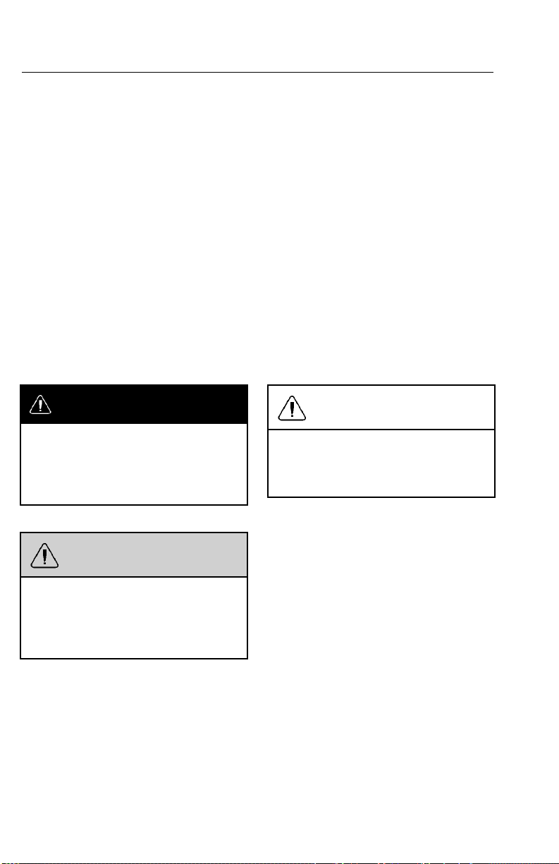
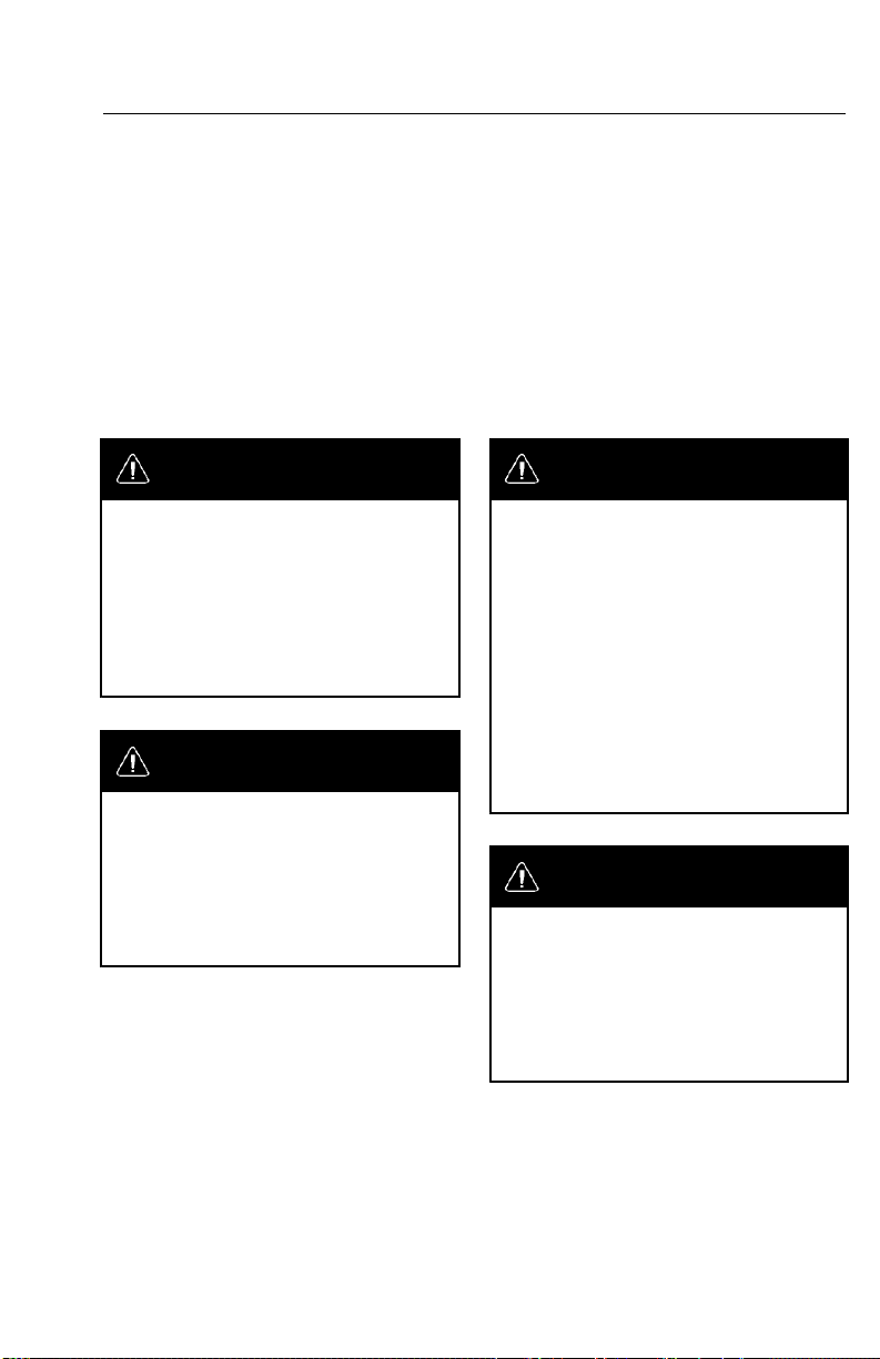
DANGER
Dangerindicatesanunsafepracticethat
couldresultinseriouspersonalinjury
ordeath.Adangeradvisorybanneris
inwhitetypeonablackbackground
withablackborder.
WARNING
Warningindicatesanunsafepractice
thatcouldresultinpersonalinjury.A
warningadvisorybannerisinblack
typeonagraybackgroundwithablack
border.
CAUTION
Cautionindicatesanunsafepracticethat
couldresultindamagetotheproduct.
Acautionadvisoryisinblacktypeona
whitebackgroundwithablackborder.
Note:Noteindicatesaprocedure,practice,
orconditionthatmustbefollowedinorder
forthevehicleorcomponenttofunction
inthemannerintended.
Page 10
Introduction3
ServiceProceduresandToolUsage
Anyoneusingaserviceprocedureortoolnotrecommendedinthismanualmustrst
satisfyhimselfthoroughlythatneitherhissafetynorvehiclesafetywillbejeopardized
bytheservicemethodheselects.Individualsdeviatinginanymannerfromthe
instructionsprovidedassumeallrisksofconsequentialpersonalinjuryordamage
toequipmentinvolved.
Alsonotethatparticularserviceproceduresmayrequiretheuseofaspecialtool(s)
designedforaspecicpurpose.Thesespecialtoolsmustbeusedinthemanner
described,wheneverspeciedintheinstructions.
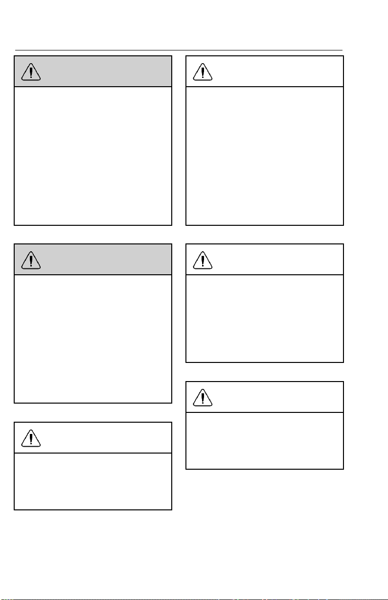
DANGER
Beforestartingavehicle,always
beseatedinthedriver’sseat,place
thetransmissioninneutral,apply
theparkingbrakes,andpushinthe
clutchpedal.Failuretofollowthese
instructionscouldproduceunexpected
vehiclemovement,whichcanresultin
seriouspersonalinjuryordeath.
DANGER
Beforeworkingonavehicle,placethe
transmissioninneutral,settheparking
brakes,andblockthewheels.Failureto
followtheseinstructionscouldproduce
unexpectedvehiclemovement,which
canresultinseriouspersonalinjuryor
death.
DANGER
Engine-drivencomponentssuchas
PowerTake-Off(PTO)units,fans
andfanbelts,driveshaftsandother
relatedrotatingassemblies,canbevery
dangerous.Donotworkonorservice
engine-drivencomponentsunlessthe
engineisshutdown.Alwayskeepbody
partsandlooseclothingoutofrangeof
thesepowerfulcomponentstoprevent
seriouspersonalinjury.Beawareof
PTOengagementornonengagement
status.AlwaysdisengagethePTO
whennotinuse.
DANGER
Donotworkunderavehiclethatis
supportedonlybyahydraulicjack.
Thehydraulicjackcouldfailsuddenly
andunexpectedly,resultinginsevere
personalinjuryordeath.Alwaysuse
jackstandsofadequatecapacityto
supporttheweightofthevehicle.
Page 11
4Introduction
WARNING
Whenworkingonavehiclebyusing
wirelesscommunicationunits,itisnot
alwaysapparenttoothersthatwork
isinprogressonthevehicle.Certain
activities,suchasactivationofcertain
vehiclecomponentsorsystems,can
causeinjurytopersonsclosetothe
vehiclewhoareunawareoftheongoing
activities.Alwayskeepaconnected
vehicleundercloseobservationwhen
usingwirelesscommunicationunitsand
informotherpersonsinthevicinityof
thevehicleabouttheongoingactivities.
WARNING
Thetemperatureoftheexhaustsystem
componentsduringtheregeneration
processcanexceed500°C(1000°F).
Variousfactors(includingambientair
temperature(AA T)anddurationofthe
regenerationprocess)determinewhen
thesecomponentswillreturntonormal
operatingtemperatureafterregeneration
hascompleted.Beextremelycareful
aroundthesehotcomponents.Contact
withthesecomponentscanresultin
seriouspersonalinjury.
CAUTION
Whenregenerationoccurs,the
temperatureoftheexhaustwillbe
elevated.DONOTparkthevehicle
withtheexhaustoutletunderlow
hangingoverheadammableobjects
suchastrees,awnings,etc.,that
couldbedamagedbyelevatedexhaust
temperatures.DONOTattemptto
regenerateinsideagarageorenclosed
areaifthetailpipeisattachedtoan
exhaustventilationsystemasthehose
materialmaynotberatedforthehigh
temperature.
CAUTION
Whentheinhibitpositionispressed,
theDPFswitchwillremaininalocked
position.Itisimportant,therefore,to
immediatelysettheswitchbacktothe
neutralpositionwhensafetodoso.
Failuretosettheswitchbacktothe
neutralpositionmayresultinanengine
derate,cloggedordamagedDPF .
CAUTION
CAUTION
Beforetowingthevehicle,placethe
transmissioninneutralandlifttherear
wheelsofftheground,ordisconnect
thedrivelinetoavoiddamagetothe
transmissionduringtowing.
SAFETY...ISNOACCIDENT!
Failuretoperformaregenerationin
atimelymannermayresultinengine
derate,cloggedAftertreatmentDiesel
ParticulateFilter(DPF)ordamageto
thelter.
REMEMBER,
Page 12

Introduction5
Everypossibleoccurrencethatmayinvolveapotentialhazardcannotbeanticipated.
Accidentscanbeavoidedbyrecognizingpotentiallyhazardoussituationsand
takingnecessaryprecautions.Performingserviceprocedurescorrectlyiscriticalto
techniciansafetyandsafe,reliablevehicleoperation.
Thefollowinglistofgeneralshopsafetypracticescanhelptechniciansavoid
potentiallyhazardoussituationsandreducetheriskofpersonalinjury .DONOT
performanyservices,maintenanceproceduresorlubricationsuntilthismanualhas
beenreadandunderstood.
•Performallserviceworkonaat,levelsurface.Blockwheelstopreventvehicle
fromrolling.
•DONOTwearloose-ttingortornclothing.Removeanyjewelrybeforeservicing
vehicle.
•ALW A YSwearsafetyglassesandprotectiveshoes.A voidinjurybybeingaware
ofsharpcornersandjaggededges.
•Usehoistsorjackstoliftormoveheavyobjects.
•NEVERrunengineindoorsunlessexhaustfumesareadequatelyventedtothe
outside.
•Beawareofhotsurfaces.Allowenginetocoolsufcientlybeforeperformingany
serviceortestsinthevicinityoftheengine.
•Keepworkareacleanandorderly.Cleanupanyspilledoil,grease,fuel,hydraulic
uid,etc.
•Onlyusetoolsthatareingoodcondition,andalwaysuseaccuratelycalibrated
torquewrenchestotightenallfastenerstospeciedtorques.Ininstanceswhere
proceduresrequiretheuseofspecialtoolswhicharedesignedforaspecic
purpose,useonlyinthemannerdescribedintheinstructions.
•Donotstorenaturalgaspoweredvehiclesindoorsforanextendedperiodoftime
(overnight)withoutrstremovingthefuel.
•Neversmokearoundanaturalgaspoweredvehicle.
Page 13

6V-MACCo-PilotOperator’sManual
SYSTEMOVERVIEW
SystemSummary
Thevehiclemanagementandcontrol(V-MAC)IVSystemisanelectronicengine
controlsystemconsistingofthefollowingmajorcomponents:
•EngineControlModule(ECM)
•GaugeDriverModuleGDM(MRUandLEUmodelsonly)
•InstrumentCluster
•VehicleElectronicControlUnit(VECU)
Toenablevehiclemanagementandcontrol(V-MAC)IVtoperformitsengine
managementandcontrolfunctions,thefollowingsensorsprovideinformationto
thesystem.
•AirBrakeApplicationSensor
•AirSuspensionSensor
•Air-HumiditySensor
•AmbientAirTemperature(AAT)Sensor
•IntakeManifoldPressure(IMP)Sensor
•IntakeManifoldAirTemperatureSensor
•CamshaftPosition(CMP)Sensor
•EngineCoolantLevel(ECL)Sensor
•EngineCoolantTemperature(ECT)Sensor
•CrankshaftPosition(CKP)Sensor
•EGRTemperatureAftercoolerSensor
•CrankcasePressure(CCP)Sensor
•EngineExhaustGasRecirculation(EGR)DifferentialPressureSensor
•FrontDriveAxleTemperatureSensor
•FuelPressureSensor
•InteriorCabTemperatureSensor(Optional)
•EngineOilLevel(EOL)Sensor
•EngineOilTemperature(EOT)Sensor
•EngineOilPressure(EOP)
•PrimaryandSecondaryAirPressureSensor
•RearDriveAxleTemperatureSensor
•AcceleratorPedalPosition(APP)Sensor
•TransmissionOilT emperatureSensor
•EngineTurbochargerSpeedSensor
•VehicleSpeed(RoadSpeed)Sensor
Page 14

V-MACCo-PilotOperator’sManual7
•WaterinFuelFilterSensor
Thefollowingswitchesandfunctionsarealsomonitoredtoprovideinformation
relatedtodriveractions.
•A/CPressureSwitch(Optional)
•ClutchPedalPosition(CPP)Switch
•EngineBrakeLowandHighSwitch(Optional)
•FanClutchOverrideSwitch(Optional)
•IdleShutdownOverrideSwitch(Optional)
•Ignitionkey
•PowerTakeoff(PTO)Switches(Optional)
•ServiceBrakeandParkingBrakeSwitches
•Set/ResumeSwitch
•SpeedControlOn/OffSwitch
•StarterEngagedSwitchInput(Optional)
•TorqueLimitingSwitch(Optional)
Thismanualprovidesacompletedescriptionofthesystemcomponents,their
functionsandlocationsonthevehicle.
Page 15
8V-MACCo-PilotOperator’sManual
SYSTEMCOMPONENTS
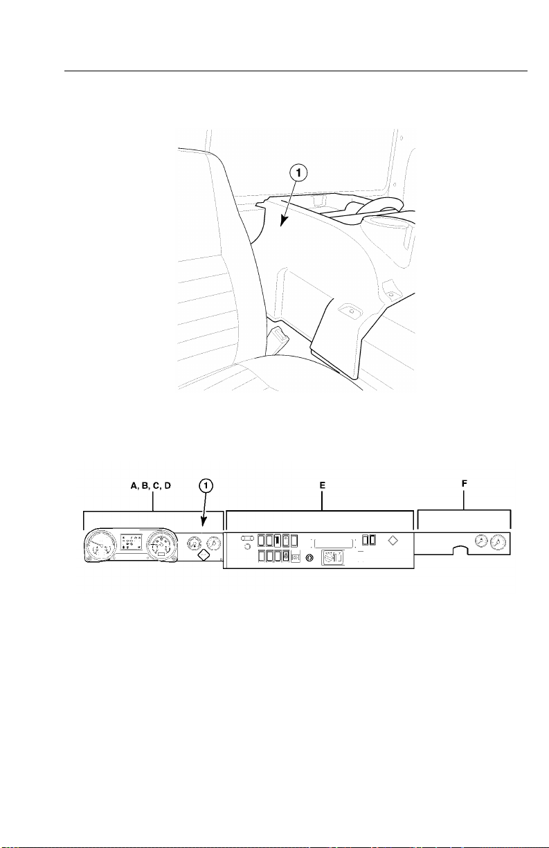
VehicleElectronicControlUnit(VECU)
TheV ehicleElectronicControlUnit(VECU)ismountedunderneathpanelDas
shownin.(CHU/CXU/GUmodelshown.)
TheV ehicleElectronicControlUnit(VECU)isanelectroniccontrolmodulewhich
providesawidevarietyoffunctionsincluding:
•CruiseControl
•DiagnosticTroubleCode(DTC)Logging
•DifferentialLocking
•IdleShutdown
•MaintenanceInformation
•RoadSpeedLimiting
•SpeedControl
•TheftDeterrence
C0035358
VECULocation
Page 16

V-MACCo-PilotOperator’sManual9
C0035359
VECU
Page 17

10V-MACCo-PilotOperator’sManual
EngineControlModule(ECM)
TheEngineControlModule(ECM)isanelectroniccontrolunit(ECU)locatedtothe
leftsideoftheengineandismountedtothefuelcooler,whichismountedbeneaththe
inletmanifold(seegraphreference).TheECMprovidesthefollowinginformation
andfunctions:
•IntakeManifoldPressure(IMP)
•EngineCoolantLevel(ECL)
•EngineCoolantTemperature(ECT)
•CustomerRoadSpeedLimiting
•DiagnosticTroubleCode(DTC)Logging
•EngineOilPressure(EOP)
•EngineOilTemperature(EOT)
•EngineProtection
•EngineShutdown
•EngineSleepMode
•EngineSpeed(RPM)Control(basedoncommandsfromvehicleelectroniccontrol
unit(VECU))
•ExhaustAftertreatmentSystem
•FanControl
•FuelControl
•FuelTemperature
•TimingControl
•VehicleLimitingSpeeds
EngineControlModule(ECM)Location
C0035356
Page 18

V-MACCo-PilotOperator’sManual11
EngineControlModule(ECM)(MACKMP7)
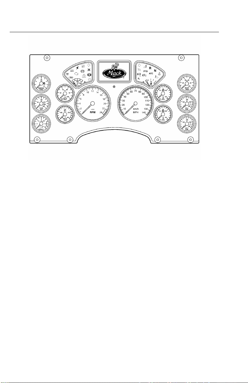
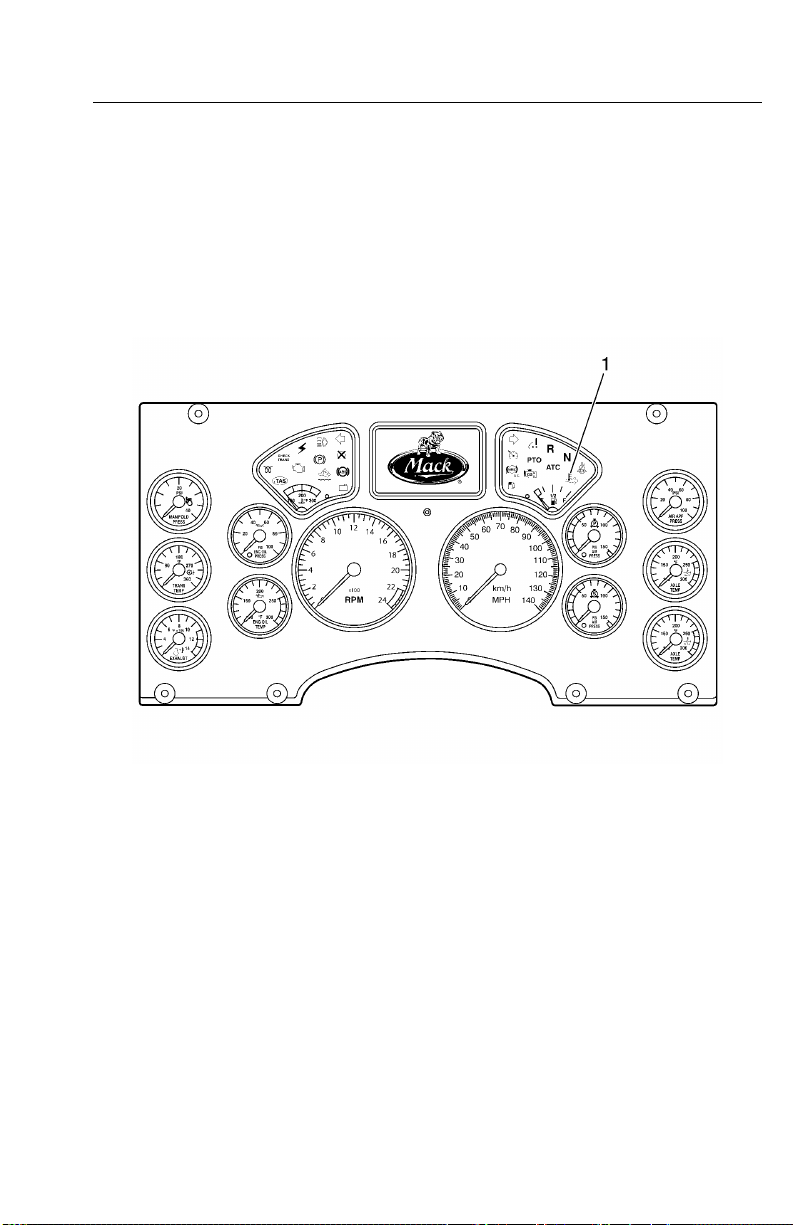
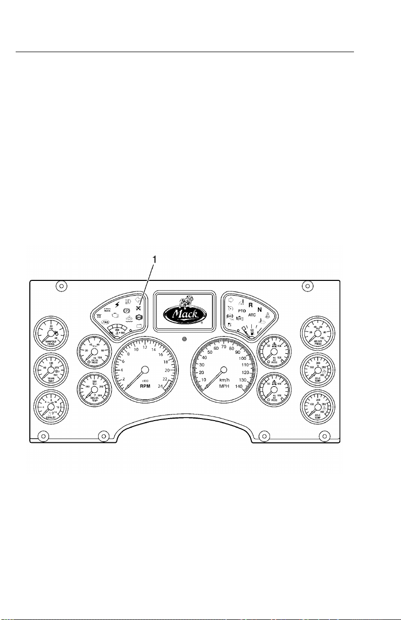
InstrumentCluster
Thevehiclemanagementandcontrol(V-MAC)IVInstrumentClusterisaone-piece
unitcomposedofgaugesandaninformationdisplay .TheInstrumentClusterreceives
informationfromtheVECUandEECUandthensendsinformationbacktotheVECU
andEECU.Informationisdisplayedwhenrequiredorrequestedviaastalkswitch
(Co-Pilot®only).
TheInstrumentClusterprovidesthefollowinginformation:
•AirBrakeApplication(Optional)
•AirFilterRestriction
•AirSuspensionPressure
•AxleOilTemperature(Optional)
•BrakeWear
•CoolantTemperature(viaEECU)
•EngineandV ehicleSpeedDisplay
•ExhaustTemperature(Optional)
•FuelLevel
•HighBeamStatus
•HighExhaustSystemTemperature(HEST)
•IntegratedTemp-A-Start™(Optional)
•InteriorandOutsideTemperature
•OilPressure(viaEECU)
•PrimaryandSecondaryAirPressure
•SpeedometerandTachometerOutputs
•TransmissionOilTemperature(Optional)
•VehicleDistance
C0035360
Page 19
12V-MACCo-PilotOperator’sManual
InstrumentClusterModule
GaugeDriverModule(GDM)
W3036315
Thevehiclemanagementandcontrol(V-MAC)IV(GDM)isablackboxcontroller
usedintheLEUandMRUmodelchassis.TheGDMcontainsawarninglightbar,an
hourmeterlocatedinthetachometerandanodometerlocatedinthespeedometer .
Aseparatepushbuttonisavailabletotogglethroughdifferentfunctionssuchasto
retrievefaultcodesandviewtripinformation.
TheGDMprovidesthefollowinginformation:
•AirBrakeApplication
•AirCleanerRestriction
•AirSuspensionPressure
•AxleOilTemperature
•BrakeWear
•EngineCoolantTemperature(ECT)(viaenginecontrolmodule(ECM))
•EngineandV ehicleSpeedDisplay
•EngineExhaustGasTemperature(EGT)
•FuelLevel
•HighBeamStatus
•HighEngineEGT
•EngineOilPressure(viaECM)
•PrimaryandSecondaryAirPressure
•SpeedometerandTachometerOutputs
Page 20
V-MACCo-PilotOperator’sManual13
•TransmissionOilT emperature
•VehicleDistance
Figure6—LocationofGDM(PassengerSideAgainstBackofCab)
C0035357
Figure7—LocationofGDM
C0035431
Page 21

14V-MACCo-PilotOperator’sManual
INDICATORS,LIGHTSANDDASHBOARD
SWITCHES
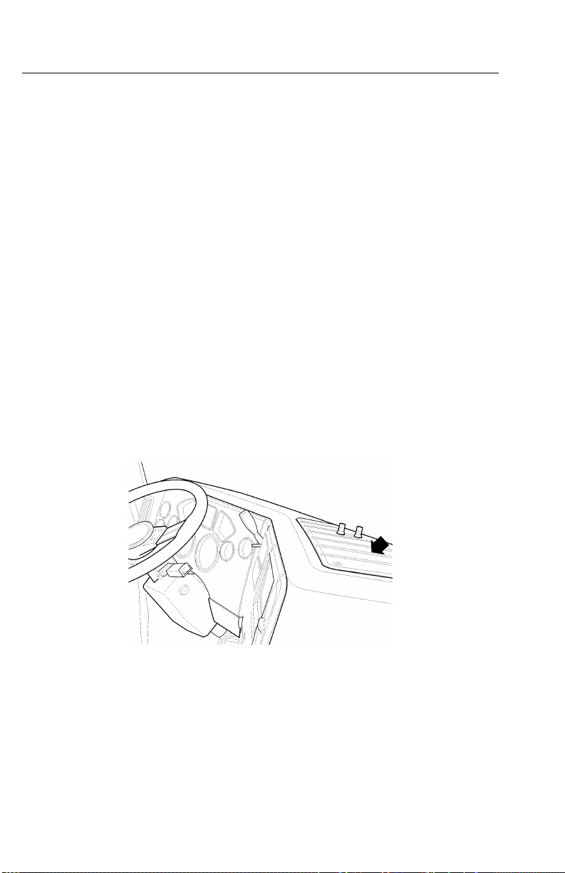
CabandDashboardSwitches
Variousfunctionsofthevehiclemanagementandcontrol(V-MAC)IVsystemare
controlledbytheoperatorthroughswitcheslocatedonthedashboard(CHU/CXU/
GUmodelshowninFigure8).Thesefunctionsinclude:
•CruiseControl
•DaytimeRunningLightsOverrides(Optional)
•EngineBrakeOperation(Optional)
•EngineSpeed(RPM)Control
•ExhaustAftertreatmentSystem
•FanOverride(Optional)
•IdleShutdownOverrideOperation(Optional)
•IntegratedTemp-A-Start™(Optional)
•PTOOperation
Cruisecontrolandenginespeedcontrolfunctionsareexplainedinthismanualin
“CRUISEANDENGINESPEEDCONTROL”,page42.
Inadditiontotheseoperator-selectableswitches,additionalswitchesprovide
informationtotheV ehicleElectronicControlUnit(VECU)throughnormaldriving
activitiessuchasapplyingtheservicebrakes,parkingbrakesordisengagingthe
clutch.Thelocationoftheseswitchesisasfollows:
•Clutchpedalposition(CPP)switch
•Parkingbrakeswitch,locatedinlinewithintheparkingbrakecircuit
•Servicebrakeswitch,locatedinlinewithinthebrakesystem
Page 22

V-MACCo-PilotOperator’sManual15
Figure8—CabandDashboardSwitches(Example)
C0035362
Page 23
16V-MACCo-PilotOperator’sManual
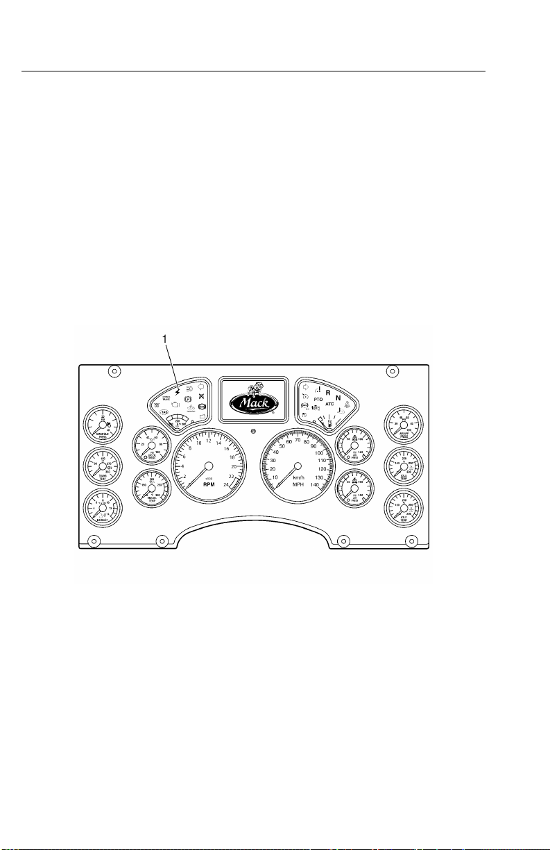
ElectronicMalfunctionIndicator
Theelectronicmalfunctionindicator,amberincolor,illuminatestoalertthedriverof
anelectricalproblemwiththevehiclemanagementandcontrol(V-MAC)IVsystem.
Thevehiclemanagementandcontrol(V-MAC)IVsystemdoesaself-testwhenthe
ignitionkeyisturnedtotheONposition.Theelectronicmalfunctionindicatorstays
onwhilethistestisbeingperformed(approximatelysixseconds).Aftertheself-test
iscompleted,theindicatorwillturnoffandremainoffunlessaproblemisdetected
byvehiclemanagementandcontrol(V-MAC)IV .Iftheindicatorturnsonwhilethe
vehicleisbeingdriven,vehiclemanagementandcontrol(V-MAC)IVhasdetecteda
problem.Inmostcircumstances,thevehiclewilloperateeventhoughtheindicator
ison;however,engineperformancemaybeaffected.
Foranexplanationoffaultcodeactivationandinterpretation,andacompletelisting
ofthesecodes,pleasereferto“DiagnosticTroubleCodes(DTCs)”,page65ofthis
manual.
Figure9—ElectronicMalfunctionIndicator
W3036326
Page 24
V-MACCo-PilotOperator’sManual17
HighExhaustSystemTemperature(HEST)
Indicator
TheHighExhaustSystemT emperature(HEST)indicator,amberincolor,illuminates
toalertthedriverwhenengineexhaustgastemperatures(EGT)arehigh.TheHEST
indicatorwillalsoilluminateduringaaftertreatmentdieselparticulatelter(DPF)
parkedregenerationeventandwillturnoffaftertheregenerationiscompletedand
theexhaustEGThasreturnedtonormal.ForadditionalinformationabouttheHEST
indicator,pleasereferto“AftertreatmentDPFSmartSwitch”,page22.
Figure10—HighExhaustSystemT emperature(HEST)Indicator
W3036496
Page 25
18V-MACCo-PilotOperator’sManual
ShutdownWarningIndicator
TheShutdownW arningindicator,redincolor,illuminatesiftheenginecoolantlevel
(ECL)isbelowtheminimumlevelallowed,theengineoilpressure(EOL)isbelow
theminimumallowed,theenginecoolanttemperature(ECT)oraftertreatmentdiesel
particulatelter(DPF)sootleveltriggerareabovethemaximumallowed.Some
vehiclesalsohaveoptionalshutdownfunctionsavailablewhenthetransmission
temperatureorengineexhaustgastemperatures(EGT)areabovemaximumallowable
limits.
Duringashutdownevent,vehiclemanagementandcontrol(V-MAC)IValsoprovides
anaudiblealarm.Thealarmwillalsosoundandtheredshutdownindicatorwillturn
onwhenvehiclemanagementandcontrol(V-MAC)IVdetectsaproblemorexcessive
periodsofidling.Shuttingtheenginedowniswarranted.
Theshutdownwarningindicatorisusuallylocatedontheleft-handsideonthedash
cluster.
Figure11—EngineShutdownWarningIndicator(Red)
W3036501
Page 26

V-MACCo-PilotOperator’sManual19
vehiclemanagementandcontrol(V-MAC)IVcanbeprogrammedtoactuallyshut
downtheengineifconditionswarrant(lowcoolant,lowEOL,highengineoil
temperature(EOT),highECT ,highengineEGTorhighautomatictransmission
oiltemperatureifsoequipped).Shutdownismandatoryforcrankcasepressure
(CCP).Withthisoptionenabled,theenginewillautomaticallyshutdownwithin
approximately30secondsaftertheredSHUTDOWNindicatorturnsonandthealarm
activates(providedthevehicleisnotmovingabovetheroadspeedthreshold).
Page 27

20V-MACCo-PilotOperator’sManual
EngineDerate
Forsomeconditions(seetablebelow),anenginederatecanoccurrstandifa
conditionworsens,thenanengineshutdowncanoccur.
CONDITIONENGINEDERA TE
Intake
ManifoldAir
Temperature
Engine
Turbocharger
Compressor
Deratestartsat120°C(248°F).
Fullderate(100%)occurswhen
temperatureisat140°C(284°F).
Deratestartsat245°C(473°F).
Torqueisderateddownto100%
at250°C(482°F).
Outlet
Temperature
Engine
ExhaustGas
Recirculation
(EGR)
Temperature
Crankcase
Pressure(CCP)
HighEngine
Coolant
Temperature
(ECT)
Iftemperatureexceeds220°C
(428°F)formorethan20seconds
witha30secondperiod,derate
starts.
Iftemperaturereaches240°C
(464°F),a100%derateoccurs.
Ifachangeinpressure(difference
betweentheCCPandbarometric
pressure(BARO))risesabout5
kPa(0.725psi)withanoffset&0.5
kPa/s(0.07psi/s)andstaysover5
kPa(0.725psi)formorethan80%
ofthetimeduring1second,the
enginewillfullyderate(100%),be
forcedtoidle,andshutdown.
Deratestartsat106.75°C
(224.15°F)andrampsdown
to12%derate.T orqueiskept
constantuntilthetemperature
reaches107.25°C(225.05°F).
Deratestartsagainat107.4°C
(225.32°F)andrampsdownto
32%derate.
Torqueisderateddownto100%at
108.4°C(227.12°F).
ENGINE
SHUTDOWN
Noengine
shutdown.
Noengine
shutdown.
Noengine
shutdown.
Engineshutdown.Redengine
INDICATOR
LIGHTS
Nowarning
indicators.
Nowarning
indicators.
Nowarning
indicators.
shutdown
indicator.
Amber
malfunction
indicatorlights
at107.2°C
(224.96°F).
Redengine
shutdown
indicatorlights
at108°C
(226.4°F).
Engine
shutdownif
temperature
risesto109°C
(228.2°F).
Page 28

V-MACCo-PilotOperator’sManual21
CONDITIONENGINEDERA TE
EngineOil
Temperature
(EOT)
Afteretreatment
Diesel
Particulate
Deratestartswith10%derateat
129°C(264.2°F)ormorefor75%
ofa4secondperiod.At132°C
(269.6°F)a100%derateoccurs.
ForCatalyzedA TS:Deratestarts
whensoottriggerratiois1.4and
continuesdownto20%derate.
ENGINE
SHUTDOWN
Engineshutdown
iftemperaturerises
to135°C(275°F).
Filter(DPF)
Soot
ForCatalyzedA TS:T orqueis
rampeddownto80%deratewhen
soottriggerratiois1.7.
ForNon-CatalyzedA TS:Derate
startswhensoottriggerratiois
1.15.
ForNon-CatalyzedA TS:T orque
isrampeddownto40%derate
whensoottriggerratiois1.20.Full
derateoccurswhensoottrigger
ratiois1.22.
Engine
Turbocharger
Wheel
*-ATS(AftertreatmentSystem).Pleaserefertopage26forinformationontheExhaust
AftertreatmentSystem.
For11and13literengines,derate
startsat129,500RPM.Fullderate
(100%)occursat130,500RPM.
For16literengines,deratestartsat
102,500RPM.Fullderate(100%)
occursat103,500RPM.
Noengine
shutdown.
INDICATOR
LIGHTS
Amber
malfunction
indicator
lightswhen
temperature
isat129°C
(264.2°F).
Redengine
shutdown
indicator
lightswhen
temperature
isat131°C
(267.8°F).
Amber
malfunction
indicatorlights
upwhensoot
triggerratiois
1.4.
Redengine
shutdown
indicatorlights
upwhensoot
triggerratiois
1.7.
Amber
malfunction
indicatorlights
upwhensoot
triggerratiois
1.15.
Redengine
shutdown
indicatorlights
upwhensoot
triggerratiois
at1.22.
Nowarning
indicators.
Page 29
22V-MACCo-PilotOperator’sManual
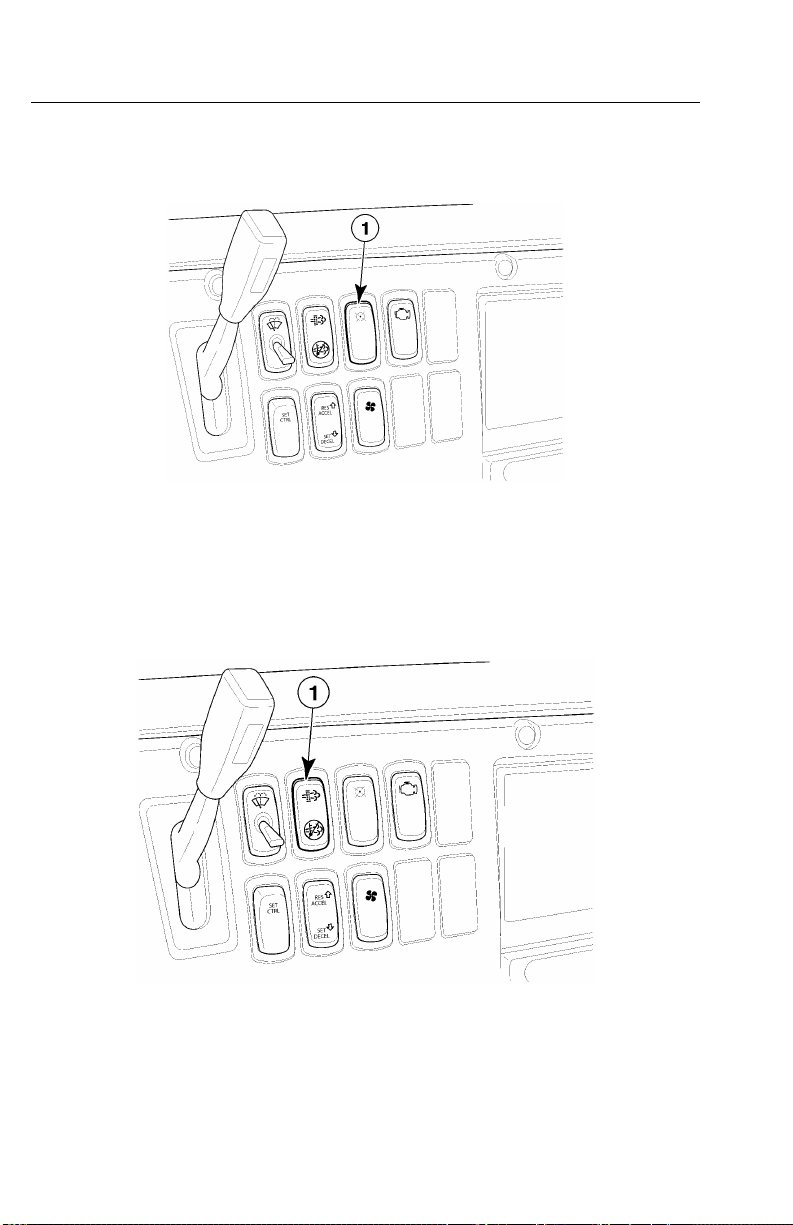
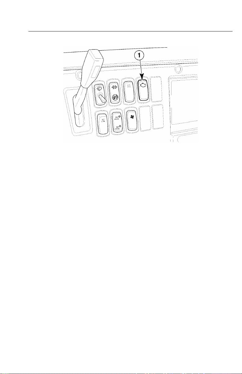
IdleShutdownOverrideSwitch
Theidleshutdownoverrideswitchpermitstheoperatortooverrideanidleshutdown.
Figure13—PanelIdleShutdownOverrideSwitch
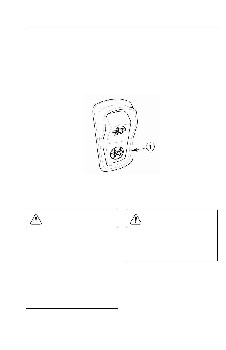
AftertreatmentDPFSmartSwitch
C0035365
Figure14—AftertreatmentDPFSmartSwitch
C0035424
Page 30
V-MACCo-PilotOperator’sManual23
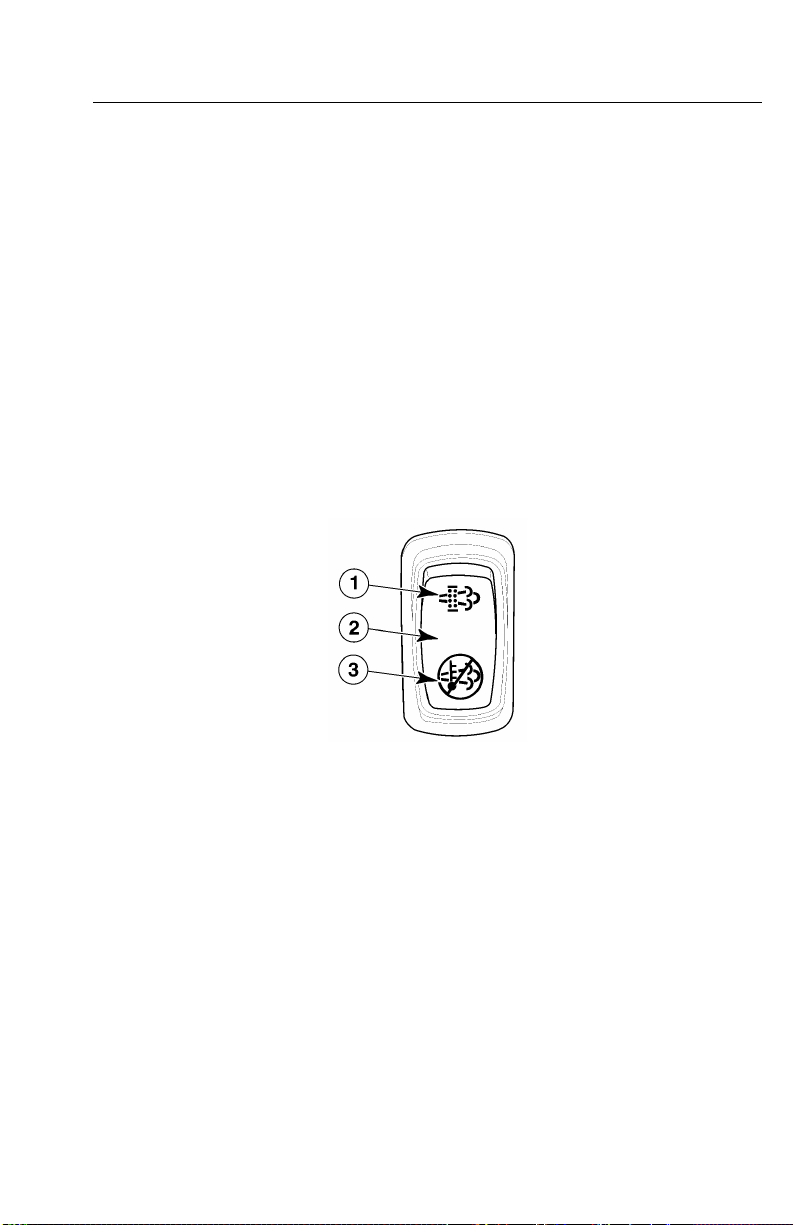
Theaftertreatmentdieselparticulatelter(DPF)smartswitchisathree-position
rockerswitchwheretheUPpositionismomentary,theMIDDLEpositionisneutral
(standbymode)andtheDOWNpositionislocked.Theswitchallowstheoperatorto
interfacewiththevehicle’sexhaustaftertreatmentsystem.
Theswitchhasseveralfunctionsasoutlinedbelow.
•IndicatesthataanaftertreatmentDPFregenerationisneededorhasstartedwhen
theiconsontheswitchareilluminated.
•IndicatesthataregenerationhasbeenstoppedwhentheDOWNpositionofthe
switchispressed,lockedandilluminated.
•StopsaregenerationeventwhentheDOWNpositionoftheswitchispressed,
lockedandilluminated.
•StartsanaftertreatmentDPFmanualregenerationeventwhentheswitchis
momentarilypressedtotheUPposition.
•Goesintostandbymodeandwaitsforregenerationwhentheswitchisinthe
MIDDLEposition.
Figure15—DPFSmartSwitch
ForadditionalinformationontheAftertreatmentDPFSmartSwitchandRegeneration,
pleasereferto“EXHAUSTAFTERTREA TMENTSYSTEM”,page24.
C0035425
Page 31

24V-MACCo-PilotOperator’sManual
EXHAUSTAFTERTREATMENTSYSTEM
AftertreatmentDPFRegeneration
ADPFintheexhaustisusedtomeetenvironmentalprotectionagency(EP A)
requirementstohelpreducesootandparticulateemissionsintotheatmosphere.The
particulatesaretypicallyremovedbycollectinginaDPF ,withcontinuousorperiodic
regenerationofthelter.Theelectricalandexhaustaftertreatmentsystemsetup
ofthevehiclewilldeterminewhenregenerationisrequired.Whenregenerationis
needed,theiconsontheDPFSmartswitchwilllightupmomentarilytonotifythe
driverandthenshutoffduringregeneration.Thehighexhaustsystemtemperature
(HEST)indicatorwilllightupontheinstrumentclustertowarnofhighexhaust
temperatures(whenvehiclespeedislessthan8km/h[5mi/h]orwhenparked).
Dependingonthevehicle’saftertreatmentsetup,regenerationcanbeperformedwhile
movingorwhenthevehicleisparked.Belowisgeneralinformationabouttheexhaust
aftertreatmentsystems.
Fornon-catalyzedexhaustaftertreatmentsystems
•Vehiclespeedmustbeatleast8km/h(5mi/h)inorderforthepassiveregeneration
tostart.
•IconsontheDPFSmartswitchwillmomentarilylightupandthenshutoffduring
theregeneration.
•HESTindicatoroninstrumentclusterwilllightuptowarnofhighexhaust
temperatureswhenvehiclespeedis8km/h(5mi/h)orless.HESTindicatorwill
shutoffwhenvehiclespeedis16km/h(10mi/h)orhigher.
•Enginespeed(RPM)willremainatidleduringregeneration(forparked
regeneration).
Forcatalyzedexhaustaftertreatmentsystems
•Vehiclespeedmustbeatleast40km/h(25mi/h)inorderforthepassive
regenerationtostart.
•Enginecoolanttemperature(ECT)is35°C(95°F)orhigher.
•IconsontheDPFSmartswitchwillmomentarilylightupandthenshutoffduring
theregeneration.
•HESTindicatoroninstrumentclusterwilllightuptowarnofhighexhaust
temperatureswhenvehiclespeedis8km/h(5mi/h)orless.HESTindicatorwill
shutoffwhenvehiclespeedis16km/h(10mi/h)orhigher.
•Enginespeedwillrampuptoaround1,100RPMduringregeneration(forparked
regeneration).
Page 32

V-MACCo-PilotOperator’sManual25
AftertreatmentDPFPassiveRegeneration
Aftertreatmentdieselparticulatelter(DPF)passiveregenerationcanbeautomatic
(nooperatorinputneededtostartregeneration)ormanual(operatorinputneededto
startregeneration).Theoperatorisnotiedthataregenerationisneededwhenthe
iconsontheDPFSmartswitchilluminate.
PleaserefertotheinstructionsbelowonhowtousetheDPFSmartswitchforpassive
regenerations.
Passive(Automatic)Regeneration
1WhentheiconsontheDPFSmartswitchlightup,maintainvehiclespeed.
2Duringregeneration,theiconsontheswitchwillshutoff.
3Regenerationwilltakebetween20and30minutestocomplete.
4Iftheregenerationprocessneedstobestoppedandperformedatalatertime,please
referto“AftertreatmentDPFInhibit/StopRegeneration”,page27forinformation.
Moving(Manual)Regeneration(IfA vailable)
1WhentheiconsontheDPFSmartswitchlightup,maintainvehiclespeedand
pressandholdthetoppartoftheswitchmomentarily .
2Duringregeneration,theiconsontheswitchwillshutoff.
3Regenerationwilltakebetween20and30minutestocomplete.
4Iftheregenerationprocessneedstobestoppedandperformedatalatertime,please
referto“AftertreatmentDPFInhibit/StopRegeneration”,page27forinformation.
Note:Dependingonthevehicle’s
conguration,itmaybepossible
toperformaparkedregenerationif
necessary.
Page 33

26V-MACCo-PilotOperator’sManual
AftertreatmentDPFParkedRegeneration
Aftertreatmentdieselparticulatelter(DPF)parkedregenerationallowstheoperator
tostartand/orstoptheregenerationmanuallywhenthevehicleisparked.The
operatorisnotiedthataregenerationisneededwhentheiconsontheDPFSmart
switchilluminate.Theoperatorshouldperformtheregenerationassoonaspossible.
PleaserefertotheinstructionsbelowonhowtousetheDPFSmartswitchforparked
regenerations.
1Movethevehicletoasafelocation,applytheparkbrakeandallowtheengineto
idle.
Note:Whenaregenerationisinprocess,theengineexhaustgastemperature
(EGT)willbeelevated.DONOTparkthevehiclewiththeexhaustoutletunder
lowhangingoverheadammableobjectssuchastrees,awnings,etc.,thatcouldbe
damagedbyelevatedexhausttemperatures.DONOTattempttoregenerateinside
agarageorenclosedareaifthetailpipeisattachedtoanexhaustventilationsystem
asthehosematerialmaynotberatedforthehightemperature.
2PressandholdthetoppartoftheDPFSmartswitchmomentarilytoinitiatethe
regeneration.
3Duringregeneration,theiconsontheswitchwillshutoff.Thehighexhaustsystem
temperature(HEST)indicatorontheinstrumentclusterwilllightuptonotify
ofhighexhausttemperatures.
4Forcatalyzedexhaustaftertreatmentsystems,theenginespeed(RPM)willramp
uptoaround1,100RPM.Fornon-catalyzedexhaustaftertreatmentsystems,the
enginewillcontinuetoidleduringtheregeneration.
5Regenerationwilltakebetween20and30minutestocomplete.
6Afterregenerationhascompletedandtheexhausttemperaturehasreturnedto
normal,theHESTindicatorwillshutoff.
7Iftheregenerationprocessneedstobestoppedandperformedatalatertime,please
referto“AftertreatmentDPFInhibit/StopRegeneration”,page27forinformation.
CAUTION
Failuretoperformanaftertreatment
DPFregenerationinatimelymanner
afternoticationmayresultinengine
derate,cloggedordamagedDPF ,and
engineshutdown.
Page 34
V-MACCo-PilotOperator’sManual27
AftertreatmentDPFInhibit/StopRegeneration
Aftertreatmentdieselparticulatelter(DPF)regeneration,whetherthemovingor
parkedvariety ,canbestoppedifthevehicleisequippedwithaDPFSmartswitch
(referto“AftertreatmentDPFSmartSwitch”,page22formoreinformation).A
regenerationshouldbestoppedonlywhennecessary .Tostoparegenerationthatisin
progress,presstheDPFSmartswitchtotheDOWNposition.Theswitchwilllock
intotheDOWNposition,andtheicononthebottomoftheswitchwillbeilluminated
toindicateregenerationhasbeenstopped.
C0035426
Figure16—Inhibit/StopRegeneration
CAUTION
WhentheDPFSmartSwitchispressed
totheDOWNposition,theswitch
willremainlockedinthisposition
andpreventaftertreatmentDPF
regenerationfromoccurring.Therefore,
itisimportanttopresstheswitchback
tothemiddlepositionandtoreturnit
tostandbymodewhensafetodoso.
Failuretosettheswitchbacktothe
MIDDLEpositionmayresultinengine
derate,acloggedAftertreatmentDiesel
ParticulateFilter(DPF),damagetothe
lterandengineshutdown.
CAUTION
FailuretoperformaaftertreatmentDPF
regenerationinatimelymannermay
resultinenginederate,acloggedor
damagedDPF ,damagetothelterand
engineshutdown.
Page 35

28V-MACCo-PilotOperator’sManual
Iftheoperatorstopsorinhibitsregenerationrepeatedly,theDPFwillbegintoclog
withsootandengineexhaustgaspressurewillincrease.Eventuallytheenginewill
derateandultimatelyshutdown.Belowisaquicklookatthetypeofregenerations,
conditionsoftheexhaustaftertreatmentsystemandtheactiontobetaken.
Page 36
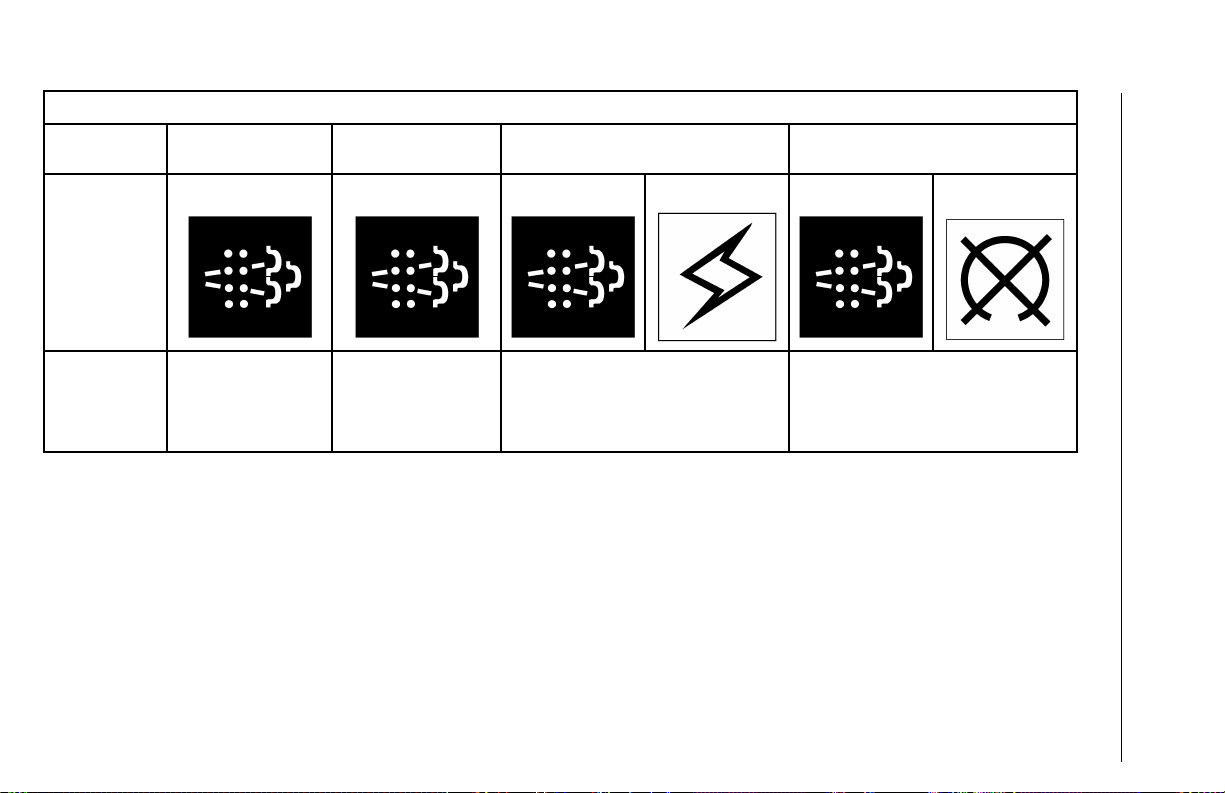
AFTERTREATMENTDPFPASSIVEREGENERATION(AUTOMA TIC)
SootLoad
Level
Indicators
Level1Level2Level3Level4
(Solid)
(Flashing)(Flashing)
(Amber)
(Flashing)
(Red)
V-MACCo-PilotOperator’sManual29
Aftertreatment
System
Condition
Regenerationneeded.
DPFisbecomingfull.
Regenerationis
required.
DPFisfull.
AftertreatmentSystemServiceRequired.
EngineDerateActive.
EnginePerformanceislimited.
SootLevelHigh.
DPFisoverfull.
AftertreatmentSystemServiceRequired.
EngineDerateActive.
SootLevelisCriticallyHigh.
DPFmaybeoveritsmaximumcapacity.
Enginemayshutdown.
Page 37

AFTERTREATMENTSYSTEMP ASSIVEREGENERA TION(AUTOMATIC)
SootLoad
Level
ActiontoTakeContinuetodriveor
Level1Level2Level3Level4
parkthevehiclein
asafelocationaway
fromoverhanging
objects(parkbrake
applied)andallow
theenginetorunand
theregenerationto
complete.
Continuetodriveor
parkthevehiclein
asafelocationaway
fromoverhanging
objects(parkbrake
applied)andallow
theenginetorunand
theregenerationto
complete.
Performaparkedmanualregeneration
IMMEDIATEL Ytoavoidfurtherengine
derateanddamagetotheDPF .
Note:Failuretoperformthe
regenerationwilltakethe
AftertreatmentSystemtoLevel4.
30V-MACCo-PilotOperator’sManual
Aseriousengineproblemhasoccurred.
Seekserviceimmediately.
Note:Parkedregenerationisno
longerpossiblefortheoperator.
Note:Failure
toperformthe
regeneration
willtakethe
Aftertreatment
SystemtoLevel2.
Regeneration
Condition
Ifpassiveregenerationisallowedtorun,thefollowingnormalprocessesmaybeobserved.
Note:Failure
toperformthe
regeneration
willtakethe
Aftertreatment
SystemtoLevel3.
•HESTindicatorwillturnoffifvehiclespeedis16km/h(10mi/h)orhigher.
•DPFSmartswitchindicatorwillshutoffduringtheregeneration.
•Regenerationtakesbetween20and30minutestocomplete.
Page 38
SootLoad
Level
Indicators(Solid)
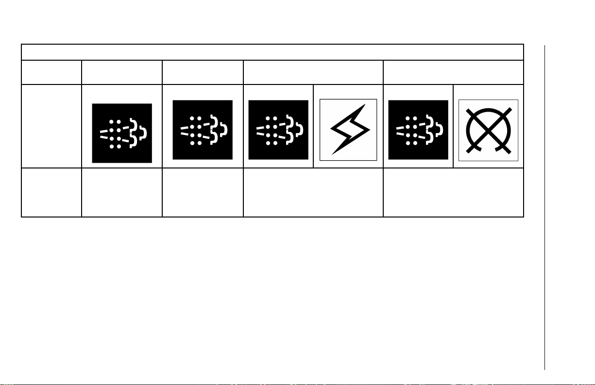
AFTERTREATMENTSYSTEMPASSIVEREGENERA TION(MANUAL)(IFA V AILABLE)
Level1Level2Level3Level4
(Flashing)(Flashing)
(Amber)
(Flashing)
(Red)
V-MACCo-PilotOperator’sManual31
Aftertreatment
System
Condition
Regenerationneeded.
DPFisbecomingfull.
Regenerationis
required.
DPFisfull.
AftertreatmentSystemServiceRequired.
EngineDerateActive.
EnginePerformanceislimited.
SootLevelHigh.
DPFisoverfull.
AftertreatmentSystemServiceRequired.
EngineDerateActive.
SootLevelisCriticallyHigh.
DPFmaybeoveritsmaximumcapacity.
Enginemayshutdown.
Page 39

AFTERTREATMENTSYSTEMPASSIVEREGENERA TION(MANUAL)(IFA V AILABLE)
SootLoad
Level
ActiontoTakeContinuetodriveand
Level1Level2Level3Level4
pressandholdthe
topoftheDPFSmart
switchmomentarily.
Alternatively,park
thevehicleinasafe
locationawayfrom
overhangingobjects
(parkbrakeapplied).
Pressandholdthe
topoftheDPFSmart
switchmomentarily.
Note:Failure
toperformthe
regeneration
willtakethe
Aftertreatment
SystemtoLevel2.
Regeneration
Condition
Ifmovingmanualregenerationisallowedtorun,thefollowingnormalprocessesmaybeobserved.
•HESTindicatorwillturnoffifvehiclespeedis16km/h(10mi/h)orhigher.
•DPFSmartswitchindicatorwillshutoffduringtheregeneration.
•Regenerationtakesbetween20and30minutestocomplete.
Continuetodriveor
parkthevehiclein
asafelocationaway
fromoverhanging
objects(parkbrake
applied)andallow
theenginetorunand
theregenerationto
complete.
Note:Failure
toperformthe
regeneration
willtakethe
Aftertreatment
SystemtoLevel3.
Performaparkedmanualregeneration
IMMEDIATEL Ytoavoidfurtherengine
derateanddamagetotheDPF .
Note:Failuretoperformthe
regenerationwilltakethe
AftertreatmentSystemtoLevel4.
32V-MACCo-PilotOperator’sManual
Aseriousengineproblemhasoccurred.
Seekserviceimmediately.
Note:Parkedregenerationisno
longerpossiblefortheoperator.
Page 40
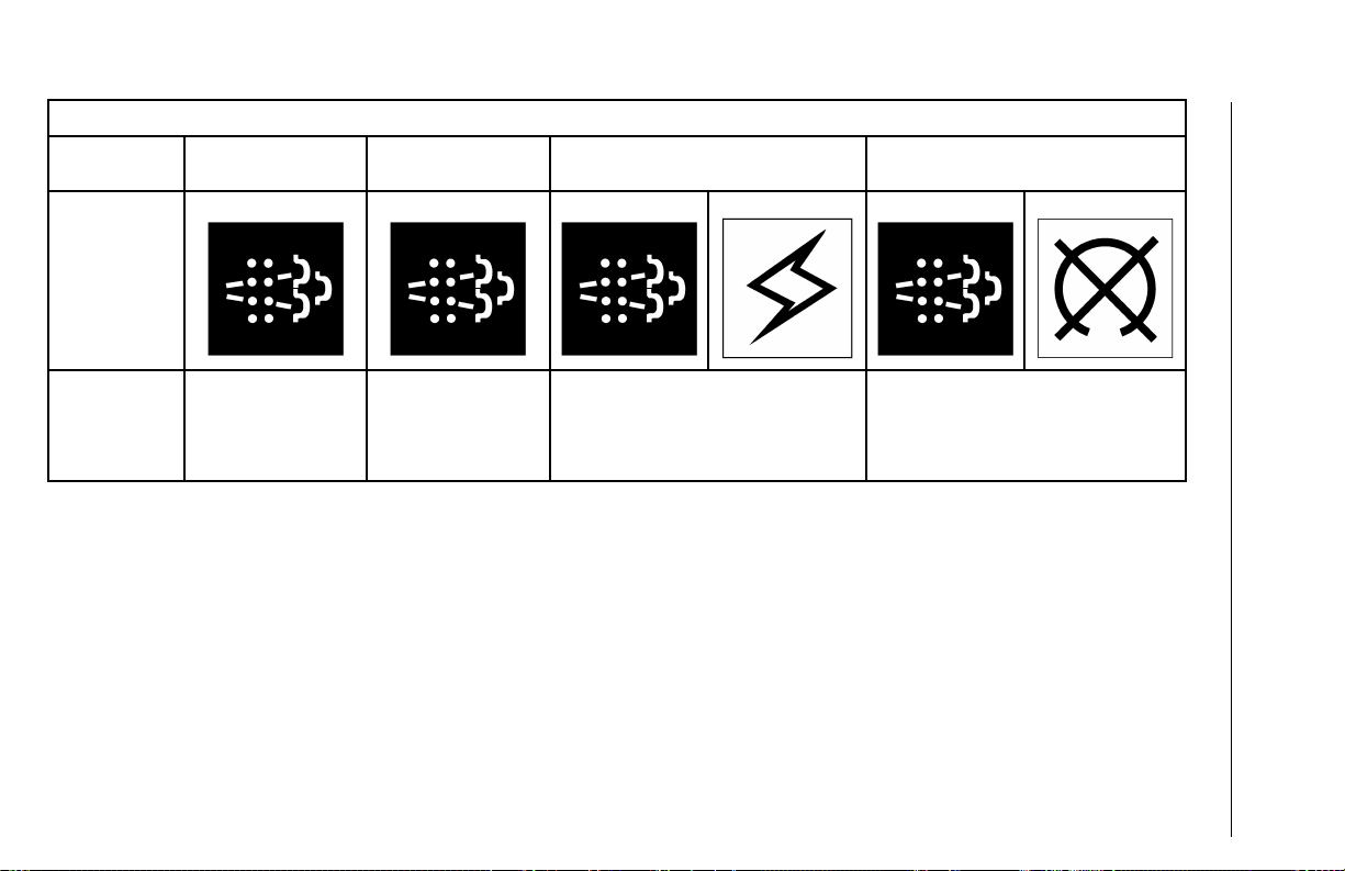
AFTERTREATMENTSYSTEMPARKEDREGENERATION(MANUAL)
SootLoad
Level
Indicators
Level1Level2Level3Level4
(Solid)
(Flashing)(Flashing)
(Amber)
(Flashing)
(Red)
V-MACCo-PilotOperator’sManual33
Aftertreatment
System
Condition
Regenerationneeded.
AftertreatmentDiesel
ParticulateFilter
(DPF)isbecoming
full.
Regenerationis
required.
DPFisfull.
AftertreatmentSystemServiceRequired.
EngineDerateActive.
EnginePerformanceislimited.
SootLevelHigh.
DPFisoverfull.
AftertreatmentSystemServiceRequired.
EngineDerateActive.
SootLevelisCriticallyHigh.
DPFmaybeoveritsmaximumcapacity.
Enginemayshutdown.
Page 41

AFTERTREATMENTSYSTEMPARKEDREGENERATION(MANUAL)
SootLoad
Level
ActiontoT akeParkthevehiclein
Level1Level2Level3Level4
asafelocationaway
fromoverhanging
objects(parkbrake
applied).
Pressandholdthe
topoftheDPFSmart
switchmomentarily.
AllowtheDPF
regenerationprocess
tocomplete.
Parkthevehiclein
asafelocationaway
fromoverhanging
objects(parkbrake
applied).
Pressandholdthe
topoftheDPFSmart
switchmomentarily.
AllowtheDPF
regenerationprocessto
complete.
Performaparkedaftertreatmentdiesel
particulatelter(DPF)regeneration
IMMEDIATEL Ytoavoidfurtherengine
derateanddamagetotheDPF .
Note:Failuretoperformthe
DPFregenerationwilltakethe
AftertreatmentSystemtoLevel4.
34V-MACCo-PilotOperator’sManual
Aseriousengineproblemhasoccurred.
Seekserviceimmediately.
Note:ParkedDPFregenerationis
nolongerpossiblefortheoperator.
Note:Failure
toperformthe
regeneration
willtakethe
Aftertreatment
SystemtoLevel2.
Note:Failure
toperformthe
regeneration
willtakethe
Aftertreatment
SystemtoLevel3.
Page 42

AFTERTREATMENTSYSTEMPARKEDREGENERATION(MANUAL)
Aftertreatment
dieselparticulate
lter(DPF)
regeneration
Condition
Ifparkedmanualaftertreatmentdieselparticulatelter(DPF)regenerationisallowedtorun,thefollowingnormalprocessesmaybe
observed.
•Enginespeed(RPM)willrampuptoaround1,100RPMandstaythereuntiltheDPFregenerationprocessis
complete.**
•HESTindicatorwillturnontowarnofhighengineexhaustgastemperature(EGTandwillstayonduring
aftertreatmentdieselparticulatelter(DPF)regeneration.
•DPFSmartswitchindicatorwillshutoffduringtheaftertreatmentdieselparticulatelter(DPF)regeneration.
•Aftertreatmentdieselparticulatelter(DPF)regenerationtakesbetween20and30minutestocomplete.
•HESTindicatorwillturnoffafteraftertreatmentdieselparticulatelter(DPF)regenerationiscompleteand
exhausttemperatureshavereturnedtonormal.
**Enginespeedrampupconditionforcatalyzedexhaustaftertreatmentsystems
V-MACCo-PilotOperator’sManual35
Page 43

36V-MACCo-PilotOperator’sManual
DPFInhibitRoadSpeedLimiting(RSL)
Theaftertreatmentdieselparticulatelter(DPF)smartswitchcanbelockedintothe
DOWN(orInhibitRegen)positionbythedriver.IftheDPFsmartswitchremainsin
thelockedposition,thefollowingvehiclespeedlimitingwilloccur:
•VehicleMoving.IfvehicleismovingwiththeDPFsmartswitchinthelocked
(DOWN)position,thevehiclespeedlimitwilldecreasedownto16km/h(10mi/h)
belowthecurrentvehiclespeeduntilthedriverreleasestheswitchbacktothe
neutral(MIDDLE)position.
•VehicleStationaryandthenMoving.IfthevehicleisstationarywiththeDPF
smartswitchinthelocked(DOWN)positionandthedriverthenbeginstomove
thetruck,thevehiclespeedwillbelimitedto16km/h(10mi/h)untilthedriver
releasestheswitchbacktotheneutral(MIDDLE)position.
Figure17—DPFInhibitRoadSpeedLimiting(RSL)
C0035426
Page 44

V-MACCo-PilotOperator’sManual37
AftertreatmentDPFRegenerationandPTO
Operation
Foraftertreatmentdieselparticulatelter(DPF)regenerationtooccur,enoughheat
mustbegeneratedinthedieseloxidationcatalyst(DOC).Heatisgeneratedby
increasingenginespeed(RPM)toaround1,100RPMonvehicleswithacatalyzed
aftertratmentsystem.ForvehiclesthatoperateapowertakeoffandhaveaDPF,the
PTOmusthaveamaximumratedspeedabovetheminimumRPMlistedinthetables
belowsothataftertreatmentdieselparticulatelter(DPF)regeneration(whether
automaticormanual)canoccurwhencommanded.
C0035438
Figure18–MinimumEngineSpeedsforMP7withCatDPF
C0035439
Figure19—MinimumEngineSpeedsforMP8withCatDPF
C0035442
Figure20—MinimumEngineSpeedsforMP10withCatDPF
Note:ForvehiclesequippedwithacatalyzedDPF ,thePTOmustbeactivatedbya
switchthatprovidesbothengagementandspeedinformationtothevehicleelectronic
controlunit(VECU)whenthePTOisengaged.Thevehicleoperatormustuseengine
speedcontroltosetenginespeedwhenthePTOisinoperation.
Page 45

38V-MACCo-PilotOperator’sManual
C0035440
Figure21—MinimumEngineSpeedsforMP7withCatDPFV ehicle21173561
Note:Beginningwith21198958andnewersoftware,theonlyrequirementfor
aftertreatmentdieselparticulatelter(DPF)regenerationonvehiclesequippedwith
anMP7withnon-catalyzedDPFandPTOisnolessthan650RPM.Altitudeand
temperaturearenolongerfactorsforaftertreatmentdieselparticulatelter(DPF)
regenerationandPTOoperation.
AftertreatmentDPFRegenerationandPTO
Engaged
Ifaftertreatmentdieselparticulatelter(DPF)manualstationaryregenerationswith
thepowertakeoff(PTO)engagedarerequired,thevehiclemustbeconguredas
follows:
•SetparameterEnableManualRegenDuringPTO(JAC)to“Y es”or“On”
usingVCADS.Thisparametercanbefoundinthe“Misc.V ehicleSettings”
sectioninParameterProgramming.(AconnectiontoCentralSystemsisrequired
tosetparameterIDJAC.)
•InitiateManualStationaryRegenerationusingtheDPFsmartswitch.
•Ensuretheelectronichandthrottle(enginespeedcontrol)isactive.The
enginespeed(RPM)mustbesettogreaterthantheminimumspeedslistedin
“AftertreatmentDPFRegenerationandPTOOperation”,page37.
Ifthevehicleisnotconguredaslistedabove,manualstationaryaftertreatmentdiesel
particulatelter(DPF)regenerationwiththePTOengagedwillnotoccur.When
aftertreatmentdieselparticulatelter(DPF)regenerationdoesnottakeplace,theDPF
willbecomesoot-loaded,resultinginenginederateandeventualengineshutdown.
Page 46

V-MACCo-PilotOperator’sManual39
AftertreatmentSystemConditioning(PeriodicHeat
Mode)
Duringperiodsofextendedidling(typically8ormorehours),theaftertreatment
systemwillaccumulateunburnedhydrocarbonsthatarereleasedfromadieselengine.
Accumulationofthesehydrocarbonscanoxidizeintheaftertreatmentsystemandcan
causedamagingtemperaturespikesandpotentialhardwarefailuresuponresumed
drivingorduringaftertreatmentDPFstationaryregenerationevents.
Extendedidlingperiodsshouldbelimitedtolessthan24hoursinordertoprotectthe
aftertreatmentsystem.However,forcustomerswhoidletheirvehiclespastthe24
hourlimit,aperiodicheatmode(knownasAftertreatmentSystemConditioning),was
developedforthecatalyzedaftertreatmentsystem.
Note:AftertreatmentsystemconditioningisNOTavailableonvehiclesequipped
withanon-catalyzedaftertreatmentsystem.
AftertreatmentsystemconditioningpurgestheDPFofaccumulatedhydrocarbons
typicallyevery8to15hoursofextendedidlingtime.Theprocessisaccomplishedby
elevatingexhausttemperaturestoapproximately100to200°Cfor5to8minutes,and
byrampinguptheenginebetween1050and1400RPM(dependentonenginemodel,
ambientairtemperature(AAT)andaltitude).
Whenaftertreatmentsystemconditioningisactiveandtheenginerampsup,amessage
willappearontheCo-Pilot®Displayindicatingthatthecycleisactiveandnodriver
inputisnecessary.Whenthecycleiscompleted,theenginewillrampdowntonormal
idlingspeed.Pleasereferto“CO-PILOT®DISPLA Y”,page68formoreinformation
regardingthismessage.
Note:Itisrecommendedthattheaftertreatmentsystemconditioningcyclenotbe
interruptedwhileinprogress.Ifpossible,donotsteponthethrottle,releasethepark
brakeormoveoutofneutraluntilthecycleiscompleted(from5to8minutes).
Page 47

40V-MACCo-PilotOperator’sManual
AftertreatmentSystemConditioningandPTO
Operation
Whentheaftertreatmentsystemconditioningcyclebecomesactiveandapower
takeoff(PTO)isengaged,theenginespeed(RPM)shouldremainatthePTOset
speed,providedtheRPMandPTOengageinputsareenabled.ThePTOmustbe
activatedbyaswitchtoprovidePTOengagementandspeedinputtothevehicle
electroniccontrolunit(VECU)(sothattheenginecontrolmodule(ECM)knows
thestatusofthePTO).IftheseinputsarenotenabledandthePTOisengaged,
aftertreatmentsystemconditioningwillincreaseRPMwhencommanded,resultingin
damagetothePTO,equipmentortotheproductbeingunloaded.
Note:WhenselectingaPTOonavehiclewithaaftertreatmentdieselparticulatelter
(DPF),itisimportantthatthePTObespeciedtohaveamaximumratedspeedabove
theminimumRPM.PleaserefertoFigures18through21.
Note:ForvehiclesequippedwiththecatalyzedDPFandprolongedperiodsofengine
idletimearerequired,theenginespeedcontrolshouldnotbeusedtoincreaseRPM.
Theenginemustbeallowedtoidleasnormal.Ifprolongedengineidlingisnecessary,
itisrecommendedthattheECMbeprogrammedwithCaliforniaAirResourcesBoard
(CARB)2010compliantles.PleaserefertotheEmissionControlSystemsforMACK
Class8DieselEngines(MACKMP7andMP8Engines)manualformoreinformation.
Page 48

V-MACCo-PilotOperator’sManual41
STARTINGTHEVEHICLE
Thefollowingprocedureisusedtostartandwarmupavehiclemanagementand
control(V-MAC)IVengineduringanyambientairtemperature(AA T)condition:
Note:Releasetheclutchandmakesurethetransmissionisinneutralbeforestarting
theengine.
1TurntheignitionkeytotheONpositionclockwise.Whenthe“W aittoStart”
indicatorontheinstrumentclustershutsoff,fullyengagethestarter .Releasethe
ignitionkeyassoonastheenginestarts.
Note:Iftheenginedoesnotstartimmediately,limitcrankingperiodsto30secondsto
avoidoverheatinganddamagingthestarter.
2Aftertheenginehasstarted,warmtheengineuntilenginecoolanttemperature
(ECT)reaches60°C(140°F).Afterreaching60°C(140°F),theenginecanbeoperated
normally.
Note:Iftheenginedoesnotstartimmediately,limitcrankingperiodsto30secondsto
avoidoverheatinganddamagingthestarter.
Note:Warm-uptimecanbereducedbyincreasingengineidlespeedbetween
1000–1200RPMbyeitherapplyingthethrottlepedalorbyusingthevariablespeed
governor(electronichandthrottle)feature.Whenoperatingunloaded,theengine
mayalsobewarmedbymovingthevehicle(afteroneminuteofidlingtime)witha
“light”throttleapplicationonly .
Note:StarterProtectionwilllimitcrankingtimetoavoidoverheatingthestarter.If
thestarterhasoverheated,itwillbeforcedoffuntilithascooled.
Page 49
42V-MACCo-PilotOperator’sManual
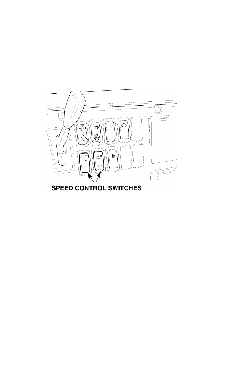
CRUISEANDENGINESPEEDCONTROL
Withvehiclemanagementandcontrol(V-MAC)IV ,theoperatorhastheabilityto
preciselycontrolenginespeed(RPM)andsetcruisecontrolspeeds,aswellassetting
theenginelowidlespeed.Thesefunctionsareperformedbyusingthespeedcontrol
switcheslocatedonthedashboard.Instructionsforsettingcruisecontrolandengine
speedcontrolaregivenonthefollowingpages.Foranexplanationofenginelowidle
adjustment,referto“LowIdleAdjustment”,page51.
C0035366
Figure22—SpeedControlSwitches
CruiseControl
EngagingCruiseControl
Thespeedcontrolfunctionsofthevehiclemanagementandcontrol(V-MAC)IV
systemareverysimilartothecruisecontrolsfoundonmostautomobiles.Thesystem
willmaintainasetspeedandwillallowaccelerationanddecelerationthroughthe
systemswitches.Cruisecontrolcanbeenabledordisabledusingcustomerdata
programming,includedintheVCADSsoftware.
Tosetthecruisecontrolfornormalhighwayoperation,thefollowingconditions
mustbemet.
1Vehicleroadspeedmustbeabovethecustomer-programmablespeedvalue(15
to35mi/h).
2Theserviceandparkingbrakemustnotbeapplied.
3Theclutchmustbeengaged(pedalreleased).
Page 50
V-MACCo-PilotOperator’sManual43
Oncetheaboveconditionsaresatised,activatethecruisecontrolasfollows.
1MovetheSpeedControlON/OFFswitchtotheONposition.
2Atthedesiredroadspeed,pressandreleasetheSETswitch.Thevehiclewill
maintainatthesetspeed.
Note:PressingthetopoftheSpeedControlON/OFFswitchactivates,orturnsthe
switchON.Pressingthebottomoftheswitchdeactivates,orturnstheswitchOFF .
Note:Toshift,simplydisengagetheclutch,changegears,thenre-engagetheclutch.
CruisecontrolwillresumeautomaticallyifprogrammedtoAutoResume.When
doubleclutching,DONOTbringtheclutchpedaltothefullyengagedposition.
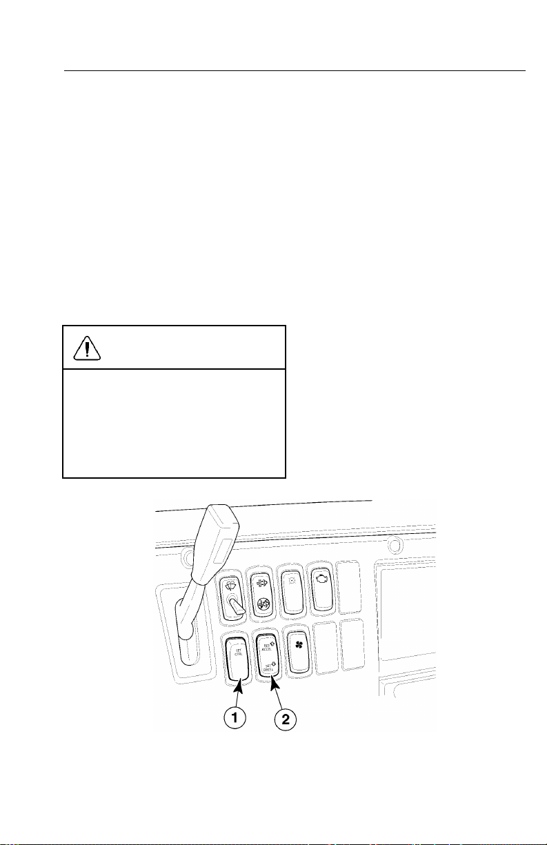
CAUTION
Transmissiongearchangesmustnotbe
madewithouttheuseoftheclutchwhile
inthecruisecontrolmode.Failureto
usetheclutchwillcausetheengine
speed(RPM)toincreasetothehigh
idlelimit,whichmaycausesevere
powertraindamage.
Figure23—SpeedControlOn/OffandSet/DecelSwitches
C0035367
Page 51
44V-MACCo-PilotOperator’sManual
AcceleratingtoaHigherSpeed
Toacceleratetoahigherspeed,threemethodsareavailable:
1.Presstheacceleratorpedal(AP).Thismethodwillacceleratethevehiclefor
aslongasthepedalispressed.(Releasethepedaltoreturntothespeedset
previously.)
2.PresstheACCELswitch.Thismethodwillacceleratethevehicleforaslongasthe
switchispressed.Thenewvehiclespeedissetwhentheswitchisreleased.(Pressthe
DECELswitchtodeceleratethevehicle.Thevehiclewilldecelerateforaslongasthe
DECELswitchispressed.Thenewvehiclespeedissetwhentheswitchisreleased.)
Note:TheMAXspeedsetbythe
acceleratorpedalmaybedifferentfrom
thatsetbytheACCELswitch.
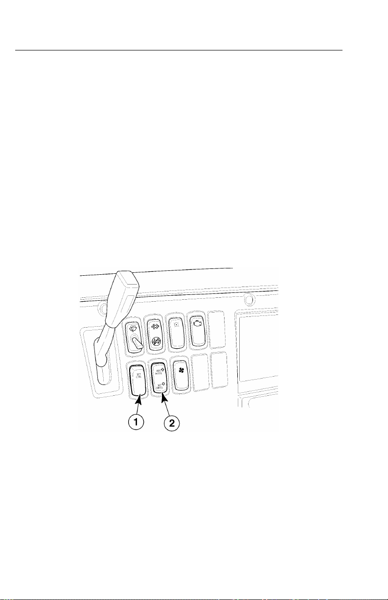
3.Thespeedcanalsobe“bumped”(knownasbumpspeed)upordown.Tapthe
ACCELsidetobumpup1mi/hortaptheDECELsidetobumpdown1mi/h.
Figure24—SpeedControlOn/OffandResume/AccelSwitches
C0035370
Page 52
V-MACCo-PilotOperator’sManual45
DisengagingCruiseControl
Todisengagecruisecontrol,useanyoneofthefollowingmethods:
1Applytheservicebrake.Thismethodwilldisengagethecruisecontrolwhile
maintainingthesetspeedinthesystemmemory.Toresumethepreviouslyset
speed,pressandreleasetheRESUMEswitch.
2Disengagetheclutch.Thismethodwilldisengagethecruisecontrolwhile
theclutchisdisengagedandwillresumethespeedcontrolwhentheclutchis
re-engaged.Thisprogrammableoptionprovidesforautomaticresumeafter
shifting.
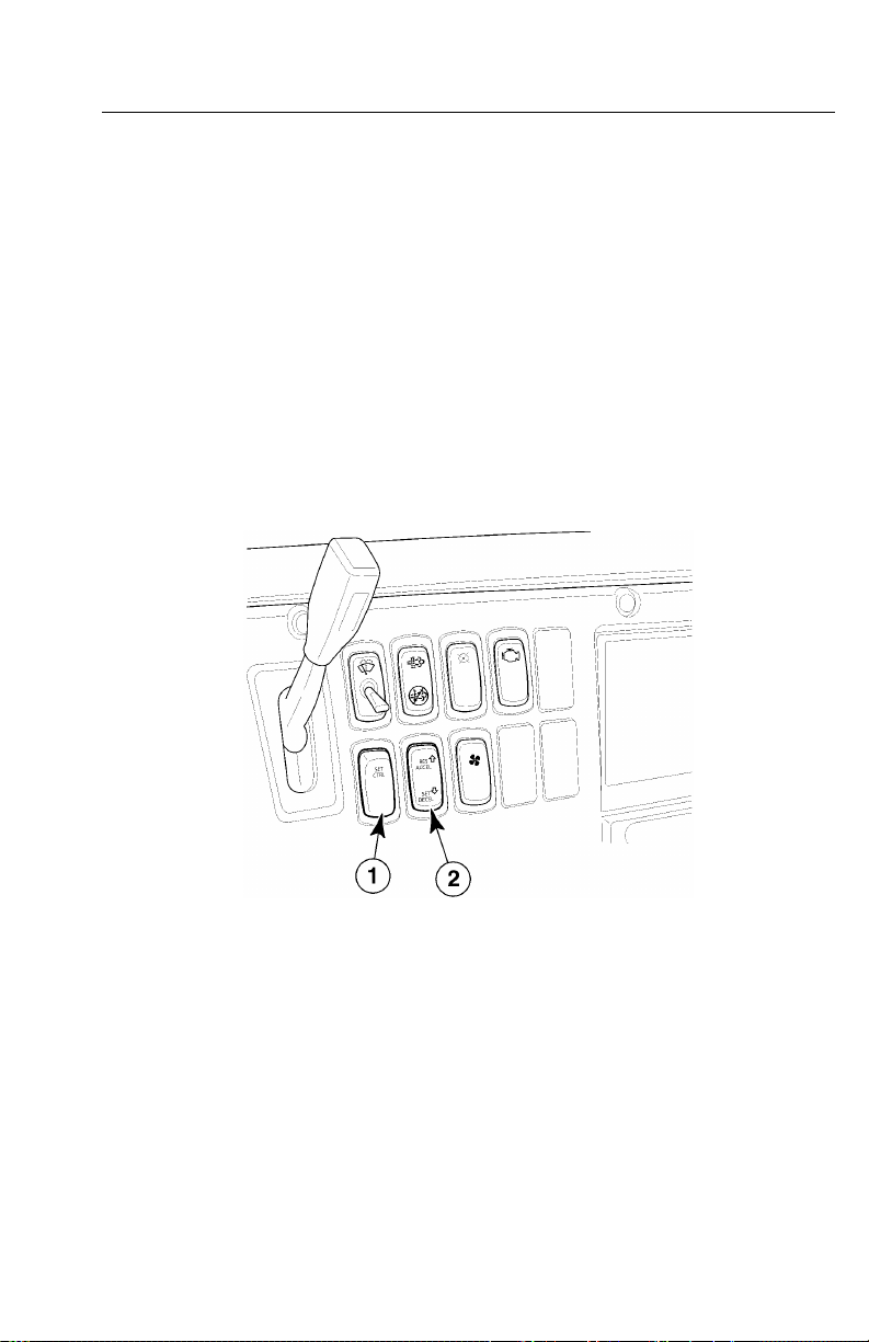
3MovetheSpeedControlON/OFFswitchtotheOFFposition.Thismethodnot
onlydisengagesthecruisecontrolbutalsoclearsthesetspeedfromthesystem
memory.Toreactivatethecruisecontrol,itisnecessarytomovetheswitchtothe
ONpositionandselectanewsetspeed.
Figure25—SpeedControlON/OFFSwitch
C0035370
Page 53

46V-MACCo-PilotOperator’sManual
EngineSpeedControl
EngineSpeedControlOperation
Thevehiclemanagementandcontrol(V-MAC)IVsystemalsoallowstheoperatorto
setandmaintainincreasedenginespeeds.Thesystemprovidestwodifferentspeed
controlfunctions:ElectronicHandThrottlecontrolandPTOcontrol.electronichand
throttle(EHT)controlsenginespeedwhenPTOisnotengaged.
Bothsystemsallowtwomodesofcontrol:
1SingleSpeedControl(SSC)increasestheengineRPMtoaspeedpreprogrammed
intothesystemmemory.ThismodeisintendedforoperationofthePTOat
maximumefciency .
2VariableSpeedControl(VSC)allowsthedrivertosetanyengineRPMwithin
thepreprogrammedlowandhighlimitssetinthesystemmemory.Thismodeis
primarilyintendedforgeneralPTOapplicationsandenginewarm-up.
Note:Brakeconditionsarecongurable,
butthestandardsettingisparkbrakeon
andservicebrakeofftoengage.
SingleSpeedControl(SSC)
Tousesinglespeedcontrolfunctions,thefollowingconditionsmustbemet:
1Forpowertakeoff(PTO)operation,thePTOmustbeengaged.Forelectronichand
throttle(EHT)operation,theservicebrakemustbeOFF.
2Theclutchmustbeengaged(notpressed).
ToactivateSSC,movetheSpeedControlswitchtotheONposition,thenpressand
releasetheSETswitch.Theenginespeed(RPM)willjumptothepreprogrammed
speed.SSCcanalsobeprogrammedforAutoSetmode.Whenenabled,simply
movetheSpeedControlswitchtotheONpositionandengagethePTOoractivate
acustomer-denedswitch(usuallysettingtheparkbrake).Enginespeedwillgo
tothepreprogrammedspeed.
Page 54

V-MACCo-PilotOperator’sManual47
VariableSpeedControl(VSC)
Tousethevariablespeedcontrolfunctions,thefollowingconditionsmustbemet:
1Theclutchmustbeengaged.
2Theparkbrakemustbeset.
ToactivateVSC,movetheSpeedControlswitchtotheONposition.Increaseengine
RPMusingtheacceleratorpedal(AP).Atthedesiredenginespeed(RPM),pressand
releasetheSETswitch.Thisspeedsettingwillbemaintained.
ToincreasetheRPM,pressandholdtheACCELswitchuntilthedesiredspeedis
attained.Or,presstheacceleratorpedaluntilthedesiredspeedisattainedandthen
pressandreleasetheSETswitch.
TodecreaseengineRPM,pressandholdtheDECELswitchuntilthedesiredspeed
isreachedandthenreleasetheswitch.
RPMcanalsobe“bumped”upordown.TaptheACCELsidetoincreaseRPM,or
theDECELsidetodecreaseRPMbythecustomer-programmedamount(default
settingis50RPM).
VSCcanalsobeprogrammedforAutoSetmode.Whenenabled,simplymovethe
SpeedControlswitchtotheONpositionandactivateacustomer-denedswitch
(usuallysettingtheparkingbrake).TheRPMwillgotothepreprogrammedminimum
speed.
The“ramprate”forEHT ,andforeachPTOinPTOcontrol,canbeprogrammed
toincreaseanddecreaseinspeedtoacustomer-speciedspeedbyusingthe
ACCEL/DECELswitch.
DisengagingSSCorVSCFunctions
Todisengagethespeedcontrolsettings,useanyoneofthefollowingmethods:
•MovetheSpeedControlswitchtotheOFFposition.
•Disengagetheclutch.
•Applytheservicebrakes.
•Releasetheparkingbrake.
Note:WhenthePTOisengagedonvehiclesequippedwithSSC,theSSCwilltake
precedenceovertheVSC.
Note:ToreactivatetheVSCtothepreviouslysetspeed,pressandreleasethe
RESUMEswitch.IftheSpeedControlON/OFFswitchisusedtodisengagethe
VSC,anewspeedmustbeset.TheRESUMEswitchwillworkonlyiftheVSCwas
disengagedbyusingtheclutchorservicebrake.
Page 55

48V-MACCo-PilotOperator’sManual
MaximumEngineSpeedLimit
Thismodeallowsthemaximumenginespeed(RPM)tobelimited,basedon
preprogrammedspeeds,whenPTOorElectronicHandThrottle(EHT)controlsare
engaged.Theenginewillnotoperatebeyondthesespeedswhenthecontrol(PTO
orEHT)isengaged.Theoperatorhasnocontroloverthisoperation,andcannot
changeoroverridethesepresetlimits.
VehicleLimitingSpeed
Theseprogrammablemodesallowthemaximumvehiclespeedtoberestrictedtoa
preprogrammedspeedlimit.Thedriverhasnocontroloverthisoperation,andcannot
changeoroverridethesepresetlimits.Anotherfeatureofthevehiclelimitingspeed
functionis“LowerGearRoadSpeedLimitFeatureActivation.”Thisoption,when
selected,willlimitvehiclespeedingearsbelowtopgeartoavaluelessthanthetop
gearroadspeedlimit.Thepurposeofthisoptionistoencouragetheoperatorto
operatethevehicleintopgear,wheretheoptimumfueleconomycanbeachieved.
Therearetwoprogrammable“topgear”V ehicleLimitingSpeeds—oneforcruise
andtheotherforusewiththeacceleratorpedal(AP).
VehicleLimitingSpeedcanalsobelimitedtoseparatevaluesforeachpowertakeoff
(PTO).
Note:Thevehiclelimitingspeedincruise
controlmodecanbelowerorequaltothe
vehiclelimitingspeedinacceleratorpedal
mode.
Pleasereferto“DPFInhibitRoadSpeedLimiting(RSL)”,page36forinformationon
theaftertreatmentdieselparticulatelter(DPF)InhibitRoadSpeedLimitingfunction.
HighAccelerationControl
Underlightload,highvehicleaccelerationconditions,themaximumengine
accelerationmaybelimitedtopreventwheelslippage.Enginespeed(RPM)willbe
limitedtoavaluejustabovetheratedspeedoftheengine.
Thisconditionshouldnotpreventthedriverfromshiftingtothenextgear.Ifthe
engineislimited,itisanindicationthatwheelslippageconditionsmaybepresentand
thatthedrivershoulddrivelessaggressivelyundertheselightlyloadedconditions.
Page 56
V-MACCo-PilotOperator’sManual49
EngineBrake
C0035372
Figure26—EngineBrakeSwitch
Toactivatetheenginebrake,movetheenginebrakeswitchtothe1stor2ndON
position.The1stpositionactivatestheenginebrakeunitfor50%power.The2nd
positionprovides100%power.Theenginebrakeswitchcanbeineither1stor2nd
ONpositionduringspeedcontroloperations,butthebrakewillfunctiononlyifno
fuelisrequestedbyvehiclemanagementandcontrol(V-MAC)IVandenginespeed
(RPM)isgreaterthan900RPM.T odisengagethebrake,movetheswitchtotheOFF
position,orpresstheacceleratorpedal(AP).
Note:Theenginebrakewillnotengage
untiltheengineoiltemperature(EOT)has
reached52°C(125°F).
ACCESSORYRELA YCONTROL
Afteranidleshutdown,vehiclemanagementandcontrol(V-MAC)IVwilldeactivate
alltheignitionpowerbusrelays,buttheenginecontrolmodule(ECM)powerrelay
willremainactiveinordertoreducecurrentdrawfromthebatteryaftertheengine
hasstopped.
Page 57

50V-MACCo-PilotOperator’sManual
PROGRAMMABLEFEATURES
Thevehiclemanagementandcontrol(V-MAC)IVsystemallowsoperatingparameters
ofcertainsystemfunctionstobeprogrammed.Thesefunctionsincludethefollowing:
•AudibleAlarm
•AutoStart(iT AS)[Optional;FutureSupport]
•AuxiliaryEngineStop(Optional)
•CruiseControlMaximumSpeed
•CruiseControlMinimumSpeed
•DrivelineParameters
•DaytimeRunningLights
•DriverDisplayParameters
•ElectronicHandThrottle(EHT)ControlParameters
•EngineBrakeDelayinCruise
•EngineGovernorParameters
•EngineProtectionParameters
•EngineSleepMode
•EngineSpeedControlParameters
•HighIdleSpeed
•FanControl
•FuelEconomyIncentiveParameters
•IdleCooldown
•IdleShutdown
•LowIdleSettings
•LowerGearRoadSpeedLimit
•ON/OFFFanControl
•OverspeedLogging
•PowerTakeoff(PTO)ControlParameters
•TamperDetection
•VehicleLimitingSpeedSettings
•VehicleSecurityLevel
•DriverPersonalOverspeedAlarm
Page 58

V-MACCo-PilotOperator’sManual51
Tochangeoperatingparameters,acomputerisusedandrequiresthatitisrunning
theVCADSsoftware.Inaddition,adatalinkadapterisalsorequiredasaninterface
betweenthescantoolandthevehiclemanagementandcontrol(V-MAC)IVsystem.
Note:Ifthereartiresizesarechanged,ortherearaxleratiosarechanged,youmust
contactyourlocalMACKTRUCKSdealer.FailuretonotifyyourlocalMACK
TRUCKSdealerofthesechangesmaycauseinaccuratespeedometerreadings.
Cruise’NBrakeEngagementDelay
Withthecruise’nbrakeengagementdelayfeature,engagementoftheenginespeed
(RPM)isdelayedincruisecontroltoreduceenginebrakecycling.Thebrakewill
engage3.2km/h(2mi/h)abovethecruisesetspeed.Theenginebrakeoperates
normallywhencruiseisnotbeingused.
EngineHighIdleSpeedifStopped
Maximumenginespeed(rpm)canbeadjustedbyusingVCADSsoftware.The
possiblehighidlesettingsrangefrom600to2,600RPM.However,theenginespeed
willnotgobelowlowidleandwillnotexceedtheOEMhighidle(usually2,100or
2,150RPM).
EngineHighIdleSpeedinUpperGears
SetsthemaximumengineRPMifthegearratioislessthan1.5.Thisfeatureis
intendedtoimprovefueleconomybylimitingefcienthighspeedengineoperation.
LowIdleAdjustment
Note:Onchassisequippedwithanautomatictransmission,thespeedcontrol
switchescannotbeusedtoadjustenginelowidlespeed.Attemptingtosetlowidle
inthismannerwillcausethevehicleelectroniccontrolunit(VECU)toenterthe
reprogrammingmoderesultingintheidlespeeddroppingto550RPM(650RPMfor
non-catalyzedexhaustaftertreatmentsystem),butitwillnotbepossibletosetanew
idlespeed.Ifthereprogrammingmodeisentered,simplyturnthespeedcontrolswitch
OFF,andidlespeedwillreturntotheoriginallysetspeed.Resettinglowidlespeedon
achassisequippedwithanautomatictransmissionrequiresascantoolrunningthe
VCADSsoftware.ConsulttheVCADSUser’ sGuideforadditionalinformation.
Page 59

52V-MACCo-PilotOperator’sManual
ThissectionexplainstheproceduretoresetthelowidlespeedusingtheSpeed
Controlswitches.
Thevehiclemanagementandcontrol(V-MAC)IVsystemallowsthelowidletobe
setwithintherangeof550to700RPM(650–700RPMfornon-catalyzedexhaust
aftertreatmentsystem).Thisprovidesexibilitytosetthelowidletothesmoothest
enginespeedforthevehicle.
Therearetwostepsrequiredtoresetthelowidlespeed.Therststepplacesthe
vehiclemanagementandcontrol(V-MAC)IVsystemintothelow-idleadjustmode.
Inthismode,vehiclemanagementandcontrol(V-MAC)IVisreadytoacceptthe
newidlespeed.
Thesecondstepistoactuallytellvehiclemanagementandcontrol(V-MAC)IV
whatthenewidlespeedwillbe.
Therstphaseintheprocessismeetingtherequirementslistedbelow .
1Thevehiclemanagementandcontrol(V-MAC)IVsystemmusthavetheLow-Idle
Adjustoptionenabledinthecustomerdataspace.Thisfunctioncanbedisabled
bythecustomer.
2Besuretherearenoactivefaultsinthesystem.
3Thevehiclemustbestationary.
4Theparkingbrakemustbeapplied.
5Theacceleratorpedal(AP)mustbeattheidleposition(notpressed).
6TheSpeedControlON/OFFswitchmustbeturnedONandOFF3timeswithin
twoseconds.Atthispoint,theidlespeedwilldropto550RPM,andvehicle
Page 60

V-MACCo-PilotOperator’sManual53
managementandcontrol(V-MAC)IVwillnowbereadytoacceptanewspeed.
BesuretoleavetheignitionkeyintheONposition.
C0035366
Figure27—SpeedControlSwitches
Note:Iftheidlespeeddoesnotdropto550RPMaftermeetingtherequirements
listed,theremaybeotherpossibleproblemswhichwillnotallowtheidletobe
reset.Refertothevehiclemanagementandcontrol(V-MAC)IVServiceManual
fortroubleshootingprocedures.
Tocompletetheresettingoftheidlespeed,continueasfollows:
1Depressandholdtheacceleratorpedaluntilthedesiredenginespeedisreached.
2Usethespeedcontrolswitchestoadjustidlespeed.
3Depressandreleasetheclutchpedaltostoreidlespeed.
Thisspeedisnowlockedintovehiclemanagementandcontrol(V-MAC)IVasthe
lowidlespeed.
Note:Todetectadropwhenresettingtheidle,itisrecommendedthatthelowidle
speedbesettoaspeedgreaterthan500RPM.
SmartIdleElevatedIdleRPMTime
Thisfeaturewilldiscontinuearampupforaperiodoftimewhentheenginespeed
(RPM)reachesitstarget.Therangeoftimecanbesetbetween0and1092minutes,
withadefaultsettingof30minutes.
Page 61

54V-MACCo-PilotOperator’sManual
IdleShutdown
Thisfeaturewillshutofftheengineafterithasbeenidleforaspeciedperiod.The
timeperiodiscustomerprogrammableusingtheVCADSsoftware.Analarmwill
warn30seconds(aprogrammabletimeframe)beforetheenginewillshutdown.The
idleshutdownoverrideswitchcanbeusedduringthis30secondperiodtooverride
idleshutdownortheservicebrakeoracceleratorpedal(AP)canbeapplied.Once
theengineshutsdown,theenginecanbere-startedbyturningtheignitionkeyto
theStartposition.
IfIdleShutdownwithsleepermodeisenabled,theshutdowncanbecancelledif
theidleshutdownoverrideswitch,servicebrakes,orAParepressedwhilethe
ShutdownIndicatorison.Idleshutdownwillbeactiveagainafterthevehiclehas
beenmovedandparked.Someoptionsonlyallowsleepermodeiftheambientair
temperature(AA T)requiresheatingorairconditioning.Iftheambienttemperatures
areoutofrange,theamberelectronicmalfunctionindicatorwillilluminateandthe
idleshutdownfunctioncanbeoverridden.IfAA Tiswithinrange,idleshutdown
remainsactiveandtheredshutdownindicatorwillilluminateasawarning(referto
theVCADSUser’sGuideformoreinformationaboutpossibleidleshutdownsettings).
Note:Idleshutdownwilln
lter(DPF)regeneration.Iftheidleshutdowntimerrequestsashutdownduring
aftertreatmentdieselparticulatelter(DPF)regeneration,theenginewillnotshut
downuntila
Note:TheCaliforniaAirResourcesBoard(CARB)requires2010modelyear
vehiclestobeequippedwithengineshavingtamper-resistantsoftwarewhichlimits
thetimethattheenginecanidleatspeedsabovelowidle(550–700RPM).Atspeeds
abovelowidle,andwithapowertakeoff(PTO)engaged,idletimewillbelimitedto5
minutes,afterwhichtheenginewillrevertbacktolowidle.V ehiclesequippedwitha
CleanIdleengineareidentiedbyalabelwhichisafxedtotheleftfrontcornerof
thehoodonconventionalmodels(CXU,CHUandGU),andthelowerportionofthe
driver’ssidedooroncab-overmodels(MRUandLEU).PleaserefertotheEmission
ControlSystemsforMACKClass8DieselEngines(MACKMP7andMP8Engines)
manualformoreinformation.
fterregenerationhasbeencompleted.
otoccurduringanaftertreatmentdieselparticulate
Page 62

V-MACCo-PilotOperator’sManual55
IdleCooldown
Thisfeatureprovidesameansofcoolingdowntheengineandturbocharger.Iftheidle
cooldownoptionisenabledusingVCADSsoftwareandthesystemsensesthatthe
turbochargermaybehot,theenginewillnotshutdownwhenthevehiclestops,the
parkingbrakeissetandtheignitionkeyisturnedtotheOFFposition.Thisfeature
allowsthedrivertolockthetruckandwalkawaywhilestillprovidingadequate
cooldown.Allswitchedaccessorieswillthenturnoffoncetheenginehasstopped.If
thisoptionisset,theenginecanbeshutdownimmediatelybycyclingtheignitionkey
orbypressingtheshutdownoverrideswitch.
Theidlecooldowntimerissetto3.5minutesassoonastheengineloadexceeds25%,
providedthattheenginehasbeenrunningatleast60seconds.Aftertheloaddrops
below25%(thelowesttriggeris35%for2minutes),thetimerbeginscountingdown.
Ifthekeyswitchisturnedoffbeforethetimerexpires,theenginewillcontinueto
rununtilthetimerreacheszero.
Ifapyrometerisinstalled,theidlecooldownfunctionwillusethepyrometerreading,
shuttingtheenginedownwhenthetemperaturedropsbelow232°C(450°F),orafter
3.5minutes,whichevercomesrst.
ThedefaultforthisoptionissetatOFFfromthefactory.
Note:Theparkingbrakemustbeonfor
theidlecooldownfunctiontowork.
FanControl
TheON/OFFfanclutch(whenequipped)canbecontrolledbyvehiclemanagement
andcontrol(V-MAC)IV .ThefollowingoptionsforON/OFFfancontrolareavailable
andcanbeprogrammedusingthepersonalcomputerrunningVCADSsoftware:
•MinimumfanONtimeforhigh-freonpressurewhilevehicleisparked
•Enableoptionalfanoverridewithoverrideswitchwhilevehicleisparked
•Enableoptionalfanoverridewithoverrideswitchwhilevehicleismoving
•Optionalfanoverridetimewhilevehicleismoving
•Optionalfanengagementwhileapowertakeoff(PTO)isengaged(notavailable
forallsoftwarelevels)
BothelectronicviscousandHDMSfansprovideconstantvariablefanspeedfor
optimumcooling.Theoptionalengagementsandoverridesavailablewiththe
ON/OFFfancontrolarealsoavailablewiththeelectronicviscousfan.
Page 63

56V-MACCo-PilotOperator’sManual
FanOverrideSwitch(Optional)
Withthefanoverrideswitch,theoperatorhastheoptionofoverridingthepreset
parametersforfanengagementtoengagethefanwhennecessary .Thefanmaybe
engagedwhilethevehicleismovingorwhileparked.Enablingthefanoverride
option,andtheparametersforoverridetimelimits,arecustomerprogrammable
usingapersonalcomputerrunningtheVCADSsoftware.Forfanoverridewiththe
vehiclemoving,thetimelimitmaybesetbetween1and25minutes;withthevehicle
parked,thereisnotimelimit.
Theoperatormaydisengagethefan(canceltheoverride)after30secondsbypressing
theoverrideswitchasecondtime.Theoperatorcannotinterferewithfanoperation
(override)ifthefanisengagedduetocoolanttemperature,inletairtemperatureor
Freonpressure.Ifthefanismanuallyengagedwiththefanoverrideswitchandengine
speedexceedsapresetoverspeed,vehiclemanagementandcontrol(V-MAC)IVwill
canceltheoverridetodisengagethefan.
Figure28—FanOverrideSwitch
C0035373
Page 64

V-MACCo-PilotOperator’sManual57
DaytimeRunningLights(DRL)OverrideSwitch
(Optional)
DaytimeRunningLights(DRL)comestandardonallMACKvehiclesandcanbe
optionedwithorwithoutanoverrideswitch.WhentheDRLoverrideswitchhasbeen
specied,differentconditionscanbeselectedthatcausetheDRLtoautomatically
activate.DRLcanbeautomaticallyturnedonwhentheparkingbrakeisreleased,the
engineisrunningorboth.Onlyoneofthesechoicesmaybeselected.UsingDRL
willilluminatethelowbeamheadlampbulbsataslightlyreducedintensity.TheDRL
functionwillmonitorhighbeamsaswell.Ifthehighbeamsareactivated,theDRL
willbetemporarilyturnedoffuntilhighbeamuseceases.
DRLsofferadditionalsafetywhendrivinginlowlightconditionswhentheoperator
maynotnormallyturntheheadlightson.Havingheadlightsonatalltimesmakesthe
vehicleeasiertospotinbadweather,duskorshadeorwhenthereisglare.DRLoffer
theabilityfordriverstogiveacourtesyashasasignalwhenitissafetomerge
intoanotherlaneonthehighway .TurningDRLofftemporarilyforslowlyrolling
throughweighstationsorwhenwaitinginlinetoreceivebillandweighingtickets
isconvenient.
WhentheoperatorpressestheDRLoverrideswitch,theheadlampswillgooutif
belowtheDRLspeedthresholdandashifabovetheDRLspeedthresholdfora
designatedperiodoftime(customerprogrammableinVCADS).Itisalsopossibleto
toggletheheadlampsbackonifnecessary.
Page 65
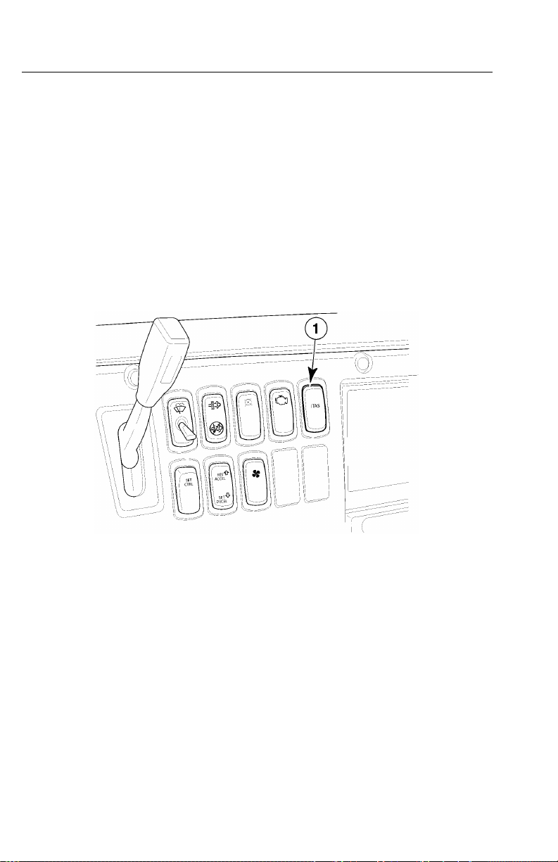
58V-MACCo-PilotOperator’sManual
IntegratedTemp-A-Start(Optional;ForFuture
Support)
IntegratedTemp-A-Start(iT AS)isafullyintegratedvehiclemanagementandcontrol
(V-MAC)IVsystemdesignedtoimprovefueleconomybyreducingunnecessary
engineidling.WheniTASisenabledviaadashswitch,thesystemwillautomatically
startandstoptheenginetomaintainaminimumenginecoolanttemperature(ECT),
minimumbatteryvoltage,oracomfortablecabandsleeperinterior.iT ASvoltageand
temperaturesettingsarefullyprogrammablethrougheitherVCADSsoftware,andvia
theCo-Pilotinstrumentclusterdisplay(ifavailableandenabled).
Note:Safetyoverrideswillpreventthe
systemfromactivatingifthetransmission
isingear,thehoodisup,ortheparking
brakeisreleased.
C0035374
Figure29—IntegratedTemp-A-StartSwitch
SpeedSensorTamperDetection
Speedsensortamperdetectionisusedtomonitorandstopunauthorizedtamperingof
thevehiclespeedlimitingfunctioninordertogainadditionaltopspeed.Iftampering
isdetected,thevehicleoperatorwillbenotiedbyadiagnostictroublecode(DTC).
Enginepowerwillbelimitedtoaprogrammedpercentageandwillcontinueuntilthe
issuehasbeencorrected.
Note:Torquelimitingwillbeinhibited
ifadriveshaftpowertakeoff(PTO)is
enabledandactive.
Page 66

V-MACCo-PilotOperator’sManual59
ELECTRICALACCESSORYCONNECTIONPOINTS
ThisMACKchassisiselectricallyreadyforconvenientinstallationofelectrical
accessories.Usethedesignatedbatterypost(+12V),groundpost,CBjack,buffered
RPMoutputs,bufferedmi/houtputs,andtheSAE/A T AJ-1708postlocatedonthe
electricalequipmentpanelfortheinstallationofanyelectricalaccessories.Each
connectionpointisdescribedbelow.
BatteryPost(BATT)
Thisisa+12volt,unswitchedbatterypowerconnection.Itcanbeusedtopower
externaldevicesthatrequirepoweratalltimes,evenwhentheignitionkeyisturned
OFF.Thissourceisprotectedbya15-ampcircuitbreaker.
IgnitionPost(IGN)
Thisisa+12volt,switchedbatterypowerconnection.Itcanbeusedtopower
externaldevicesthatrequirepoweronlywhentheignitionkeyisON.Thissourceis
protectedbya15-ampcircuitbreaker.
GroundPost(GND)
Thisisagroundconnection.Itcanbeusedasapowerreturn(−)connectionfor
externaldevices.
RPMOutput
Thisisa50%dutycycle,5-volttransistor-transistorlogic(TTL)compatible,
square-wavesignalthatiscalibratedtoprovideastandardpulserateof12pulses
perenginerevolution.
Note:Transistor-transistorlogic
compatibleofthisoutputmaybeaffected
byotherdevicesconnectedtothisoutput.
MaximumratedcurrentoftheTTLoutput
is10mA.Totalcurrentdrawofalldevices
connectedtothisoutputmustnotexceed
10mAat4volts.
Page 67

60V-MACCo-PilotOperator’sManual
Mi/hOutput
Thisisa50%dutycycle,5-voltTTL-compatible,square-wavesignalthatiscalibrated
toprovideastandardpulserateof30,000pulsespermile.
Note:TTLcompatibilityofthisoutput
maybeaffectedbyotherdevices
connectedtothisoutput.Maximumrated
currentoftheTTLoutputis10mA.Total
currentdrawofalldevicesconnectedto
thisoutputmustnotexceed10mAat4
volts.
SAE/ATAJ-1708Posts(SeriesLinkAandB)
Thisisaserialcommunicationinterface.ItconformstotheSAE/A T AJ-1708
RecommendedPracticeforSerialDataCommunicationsBetweenMicrocomputer
SystemsInHeavyDutyV ehicleApplications.
CBRadioPowerJack(CBRadio+)(Locatedon
Dashboard)
Thisisa+12volt,switchedbatterypowerconnection.Itisusedtopowerthevehicle’s
CBradio.Itisprotectedbya15-ampcircuitbreakerandwillsupplypoweronly
whentheignitionkeyisintheONposition.
CBRadioGroundJack(CBRadio−)(Locatedon
Dashboard)
Thisisagroundconnection.Itisusedasapowerreturn(−)connectionforthe
vehicle’sCBradio.
SeethefollowingillustrationsfortheCTPandCXPelectricalaccessoryconnection
pointsforelectricalequipmentpanels.
Page 68

V-MACCo-PilotOperator’sManual61
INSTRUMENTCLUSTERDISPLAY
Theinstrumentclusterdisplayisanin-dashcomponentthatletsthedrivermonitor
informationsuppliedbyvehiclemanagementandcontrol(V-MAC)IVandalso
permitsthedrivertochangefunctionstoaccommodatehisneeds.Theinstrument
clusterdisplayisuserfriendlyandpromptsthedriverwithmessagesonthedriver
informationdisplay.
DashClusterSet-UpProgramming
Somefeaturesandfunctionslistedinthissectioncanbecustomizedtomeetcompany
ordriver’sneeds.vehiclemanagementandcontrol(V-MAC)IVcanbeprogrammed
bythedealerorcustomerusingVCADSsoftwaretomakethesefeaturesavailable
throughtheinstrumentcluster.
Page 69
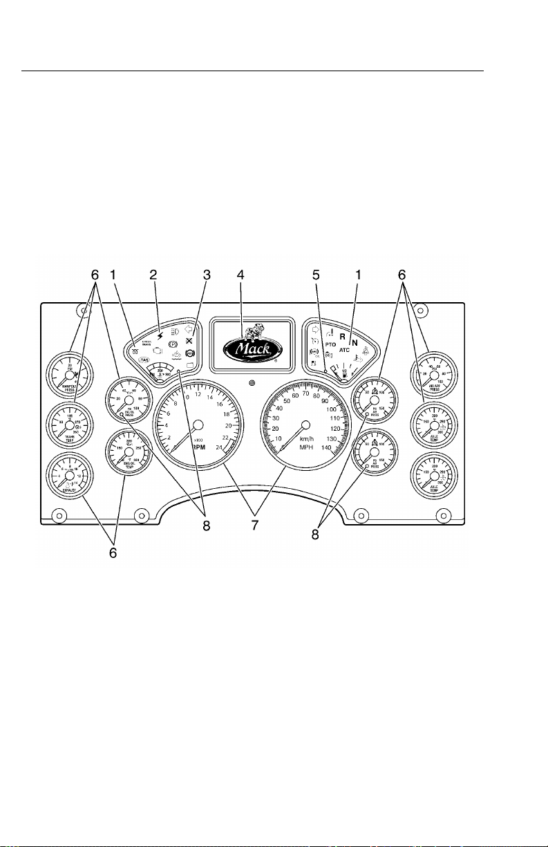
62V-MACCo-PilotOperator’sManual
InstrumentClusterComponents
Thedashclusterconsistsofthefollowingeightmajorcomponents:functionlight
indicators,electronicmalfunctionindicator,engineshutdownindicator,driver
informationdisplay,lowfuelindicator,gauges,speedometerandtachometer,onboard
diagnostic(OBD)faultandwarningindicators.Althoughnotapartofthedashcluster
components,butneverthelesspartofthedashclustertool,isthestalkswitch(for
Co-Pilot®only)locatedontherightsideofthesteeringcolumn.
Thefollowingillustrationshowstheinstrumentclusterdisplay(Co-Pilot®shown).
Figure30—InstrumentClusterComponents
1.FunctionLightIndicators5.LowFuelIndicator
2.ElectronicMalfunctionIndicator
3.EngineShutdownIndicator7.SpeedometerandTachometer
4.DriverInformationDisplay8.WarningIndicators
6.Gauges
W3036320
Page 70
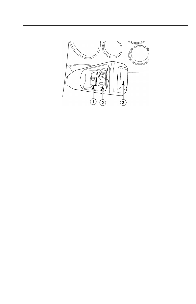
V-MACCo-PilotOperator’sManual63
Thefollowingillustrationshowsthestalk
switch.
C0035377
Figure31—InstrumentClusterComponents
Thestalkswitch(forCo-Pilot®displayonly)islocatedontherightsideofthe
steeringcolumnandcontainsthreedepressiblebuttons:ESC,Enter(↵ ↵↵)andUp&
Down.Thestalkswitchisusedtoaccess,navigate,viewandchangeinformation
availableinthedriverinformationdisplay(Co-Pilot®display).
Page 71

64V-MACCo-PilotOperator’sManual
DriverInformationDisplay
TherearetwotypesofdriverinformationdisplaysavailableforMACKTRUCKS
vehicles:basicdisplayorCo-Pilot®Display.Thebasicdisplayprovideslimited
information(currentconditions,tripinformationanddiagnosticinformation).The
Co-Pilot®Displayprovidesthedriverwithsuchinformationastime,temperature,
tripmileage,tripfuel,warninginformationanddiagnostictroublecodes(DTCs).The
driverinformationdisplayalsocontainsamenuwherethedrivercanaccessandadjust
functionssuchasmaintenance,dashclusterself-test,alarmsound,lightinglevel,time,
languagechoice,andunitsofmeasure(forCo-Pilot®only).Bothdriverdisplaysare
locatedinthecenterofthedashclusterandeasilyaccessibletothedriver .
Toenterthedriverinformationdisplay,pressandholdtheEnter(↵ ↵↵)buttononthe
stalkswitch.
Formoreinformationregardingthedriverinformationdisplay,pleasereferto
“CO-PILOT®DISPLA Y”,page68or“BASICDISPLAY”,page106.
Page 72
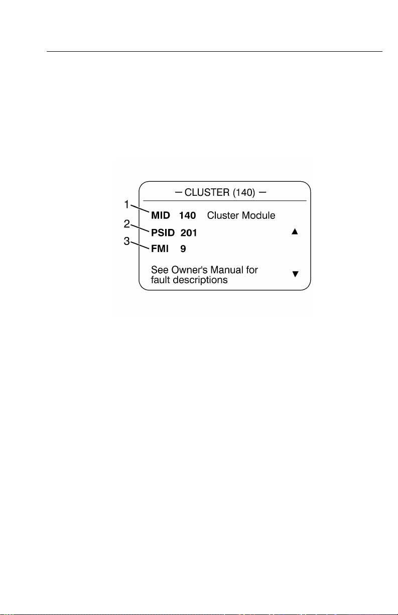
V-MACCo-PilotOperator’sManual65
DiagnosticTroubleCodes(DTCs)
ElectronicDashDisplay
DTCsareusedforisolatingandtroubleshootinganyactivefaultsinthevehicle
managementandcontrol(V-MAC)IVsystem.ActiveDTCscanbequicklyviewed
ontheelectronicdashdisplay(Co-Pilot)inthefollowingformat:
1MID—MessengerIdentierCode
2PID,PPID,PSIDorSID—ParameterIdentier,ProprietaryParameter
Identier,ProprietarySubsystemIdentierorSubsystemIdentierCode
3FMI—FailureModeIdentier
Figure32—DTCIndicator(J1587)
W3036575
Page 73
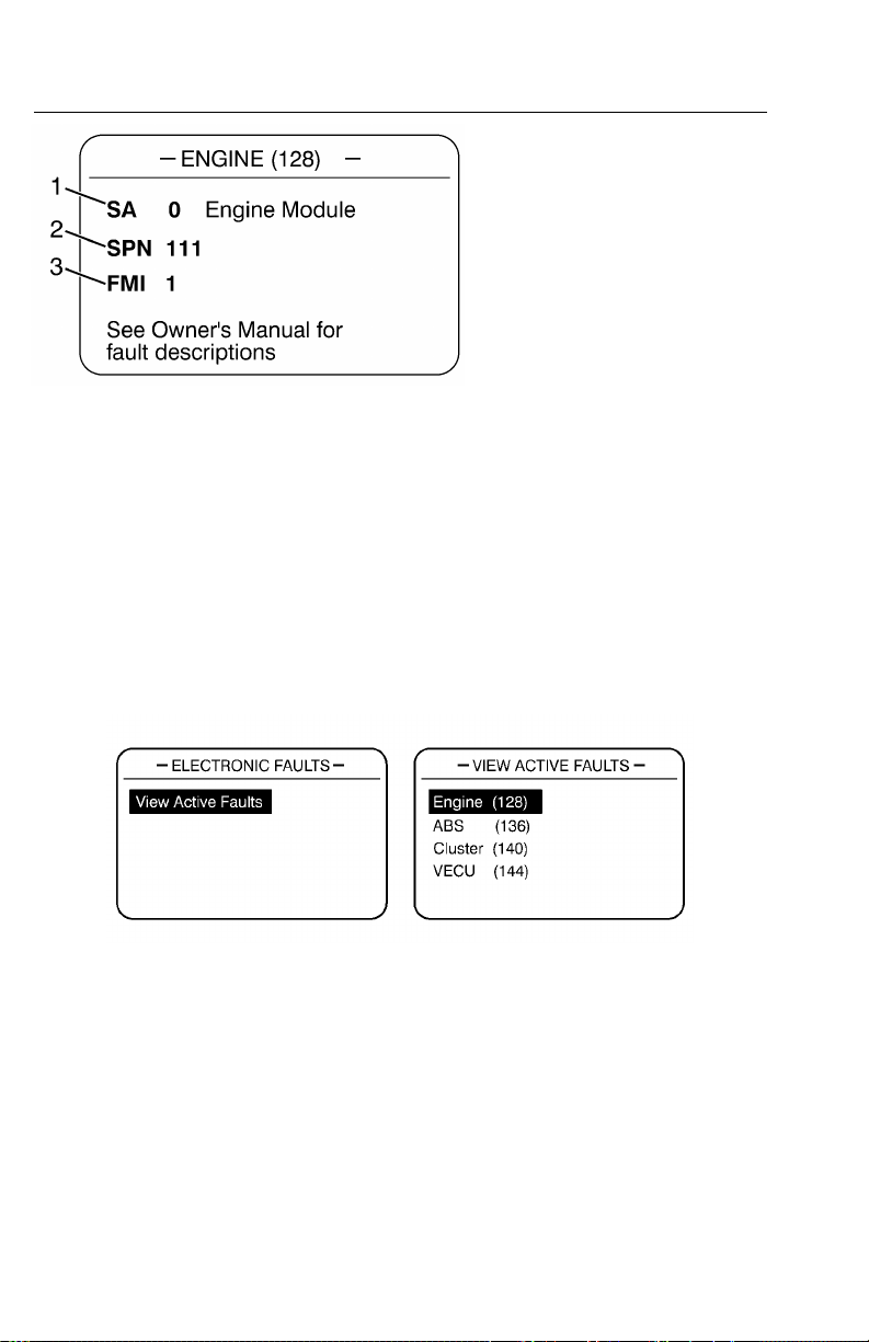
66V-MACCo-PilotOperator’sManual
W3036576
1SA—SourceAddress
2SPN—SuspectParameter
Number
3FMI—FailureModeIdentier
Figure32—DTCIndicator(J1939)
ThescreensinFig. 33,indicatethatthereisanactivePID84faultfromtransmitter128
withanFMIof4.
Figure33—ActiveDTCScreens
ThescreensinFig. 34,indicatethattherearecurrentlynoactiveDTCs.
W3036583
Page 74

V-MACCo-PilotOperator’sManual67
W3036584
Figure34—NoFaultDisplayScreens
ToviewtheDTCs(thevehiclemustbestationary),turntheignitionkeytotheON
positionanddothefollowing(refertoFigure33):
1PresstheEnter(↵ ↵↵)buttonontheStalkSwitch.TheCo-Pilotmainmenuwill
appear.
2UsetheUp&DownbuttontohighlighttheDiagnosticsmenu.
1PresstheEnter(↵ ↵↵)buttontoentertheDiagnosticsmenu.
2UsetheUp&DownbuttontohighlightElectronicFaults.
3PresstheEnter(↵ ↵↵)buttontoentertheElectronicFaultsmenu.
3Youcanviewbothactiveandinactivefaultcodes(refertoFigure33,Figure35,
andFigure36,).
1Toviewactivefaultcodes,usetheUp&DownbuttontohighlightActive
FaultsandthenpresstheEnter(↵ ↵
Note:Clearinginactivefaultcodesisonlypossibleifyouhave
Owner-Operatingprogrammingaccess.
4ToexittheCo-Pilot,presstheEnter(↵ ↵↵)buttonandthenpresstheESCbutton
twicetoreturntothemainmenu.
↵
)buttontoselect.
FormoredetailandgraphicpresentationonviewingDTC,pleasereferto
“CO-PILOT®DISPLA Y”,page68.
Page 75

68V-MACCo-PilotOperator’sManual
CO-PILOT®DISPLA Y
IntroductionandPurpose
TheCo-Pilotisanin-dashcomputerthatletsthevehicleoperatormonitorinformation
suppliedbythevehiclemanagementandcontrol(V-MAC)IVelectroniccontrol
systemandenhancethefunctionsofV-MACbyenteringrequestedinformationwith
thestalkswitch.TheCo-Pilotisvery“userfriendly”andpromptstheoperatorwith
messagesonthedisplayscreen.
BeginningwithCo-Pilot,featuresincludethefollowing:
•FuelEconomyInformation
•GuardDog™
•DriverTripandFleetTripInformation
•SpeedometerInformation
•GaugeInformation
•ElectronicFaults
•DriverMessages
•ClusterDiagnostics
•MaintenanceMonitoring(ifavailable)
•IntegratedTemp-A-Start(ifavailable)
•Set-Up(languages,units,driveroverspeedalarm,date,displaylighting)
CO-PILOTSYSTEMOVERVIEW
Set-UpProgramming
ManyCo-PilotfeaturesandfunctionslistedinthisOperator’sGuidecanbe
customizedtomeetindividualcompanyoroperatorneeds.V-MACcaneasilybe
programmedbythedealerorcustomerusingMACK’sscantoolwithVCADS
softwaretomakethesefeaturesavailablethroughtheCo-Pilot.
IfyourCo-PilotdoesnotdisplayanyofthefeatureslistedinthisOperator’sGuide,
pleaseconsultyourdealerorappropriateeetmanagementpersonnelforV-MAC
set-upreprogrammingasrequired.ProgrammableCo-Pilotfeaturesinclude:
Page 76

V-MACCo-PilotOperator’sManual69
Table4ProgrammableCo-PilotFeatures
Feature
BillofLadingEnterinBillofLadingnumberN/A
ChangeDriverChangetoanewDriverEnabled
DrainW ater(optionalandfor
possiblefuturesupport)
DriverOverspeedAlarm(for
futuresupport)
IntegratedT emp-A-Start
(optional)
MaintenanceResetResetMaintenanceitemsDisabled
DELMessages
NextFleetTripEnterthenexteettripDisabled
ResetDriverTripResetDriverT ripinformationEnabled
SetDisplaySettings
Function/SelectionsFactoryDefaultSettings
Drainsthesedimentbowl
automaticallyfrommenu
command
Setpersonalvehiclespeed
thresholdalarm
ProgramsettingsIfordered,thereareseveral
DriverentersinDriverEvent
LoggingMessages
•SetCo-Pilottimeand
date
•Setlanguage
•Setdisplaylighting,
brightnessandcontrast
•Setunitsofmeasure
TheftDeterrent(optional)EntertheftcodepasswordDisabled
HoursofService(forfuture
support)
——
Enabledautomaticallyifthe
optionisordered
parametershere.
Disabled
N/A
English
N/A
Englishunitsofmeasure
Page 77

70V-MACCo-PilotOperator’sManual
ThefollowingillustrationshowstheareasoftheCo-Pilot®CurrentConditionsscreen.
Figure36—Co-PilotCurrentConditionsScreen
W3036685
1.Time
2.Mileage
3.AmbientAirTemp(AA T)
4.InformationArea
5.SweetSpotIndicator
6.Bonus/Penalty
7.Maintenance
8.Overspeed/Idle
9.Gear(withautomatedtransmission)
10.MACKRoadStabilityAdvantage
11.MACKRoadStabilityAdvantage
TargetDetected
Thestalkswitchislocatedontherightsideofthesteeringcolumnandcontainsthree
depressiblebuttons:ESCEnter(↵ ↵↵)andUp&Down.Thestalkswitchisusedto
access,navigate,viewandchangeinformationavailableinthedriverinformation
display(Co-Pilot®only).
Page 78

V-MACCo-PilotOperator’sManual71
Thefollowingillustrationshowsthestalkswitch.
Figure37—StalkSwitch(Co-PilotOnly)
C0035377
Page 79

72V-MACCo-PilotOperator’sManual
CO-PILOTSYSTEMOVERVIEW
ESCButton
TheESC(Escape)buttononthestalkswitchtakestheCo-Pilotbacktotheprevious
screenorlevelinthemenu.
Note:TheESCbuttondoesnotfunction
atStart-Up.
Enter(↵ ↵
TheEnter(↵ ↵↵)buttononthestalkswitchselectsthehighlightedmenuitemsduring
menuselection.DuringStart-Upandwhenmovingthevehicle,theEnter(↵ ↵↵)button
isalsousedtoconrmoracknowledgeapop-upscreen.Sometimes,theEnter(↵ ↵↵)
buttontakestheCo-Pilotdisplaybacktothepreviousscreen.
↵
)Button
Up&DownButtons
TheUp&Downbuttonsattheendofthestalkswitchallowtheusertohighlightthe
variousavailablemenuitems.Sometimes,thesebuttonsareusedtoenterinformation
intothedisplays.
•UpButton—Onceatthetopofthemenuitemsthatcanbeselected,pressingthe
UpbuttonwilltaketheCo-Pilotdisplaytothelastiteminthemenu.
•DownButton—Onceatthebottomofthemenuitemsthatcanbeselected,
pressingtheDownbuttonwilltaketheCo-Pilotdisplaytotherstiteminthemenu.
Page 80

V-MACCo-PilotOperator’sManual73
CO-PILOT®LA YOUT
Note:ForthelayoutoftheBasicDriverDisplayscreens,pleasereferto“BASIC
DISPLAY”,page106
ScreenTypes
TheCo-Pilot®containssixtypesofdisplayscreens:
•Start-UpScreens—Agroupofscreensthatappearwhenthevehiclemanagement
andcontrolvehiclemanagementandcontrol(V-MAC)IVsystemisenergized.
IndividualStart-Upscreensarediscussedinmoredetailin.
•MenuScreens—Agroupofscreensthatappearwithamenuselectiondepending
onwhetherthevehicleisstationaryormoving.IndividualMenuScreensare
discussedinmoredetailin.
•AnytimeScreens—Agroupofscreensthatcanbedisplayedtoadriveratany
time(whetherthevehicleismovingorstationary).IndividualAnytimeScreensare
discussedinmoredetailin.
•StationaryScreens—Agroupofscreensthatisonlyaccessiblewhenthe
vehicleisstationary(VehicleSpeed=0).Thesescreenchoicesdisappearfromthe
tationaryMAINMENUscreenwhenthevehiclebeginsmovingandarereplaced
s
withthelastanytimescreen.IndividualStationaryScreensarediscussedinmore
detailin.
•InterruptScreens—Agroupofspecialscreensthatappearsduringstart-upor
operationtonotifythedriverofcertaincriticalinformation.WhenanInterrupt
screenappears,thedrivermustdooneofthreethings:
1Key-intherequestedinformation.
2PresstheEnter(↵ ↵
and/oralarm.
3Takeappropriateactiontocorrecttheconditionthattriggeredthealarm.
↵
)buttontoacknowledgethescreenandturnoffthewarning
Forexample,iftheDRIVERROADSPEEDALARMscreenappears,decelerateuntil
thevehiclespeeddropsbelowthelimitwhichtriggeredthealarm.
IndividualInterruptScreensarediscussedinmoredetailin.
•OptionalSystemsScreens—Agroupofspecialscreensthatareaccessible
dependinguponavailability.
IndividualOptionSystemsScreensarediscussedinmoredetailin.
Page 81

74V-MACCo-PilotOperator’sManual
CO-PILOT®STARTUPSCREENS
Whenthevehiclepowersup,theCo-Pilot®displaywillilluminateStart-Upscreens.
Dependingonthevehicle’soptions,thefollowingscreenswillappear:
•MACKLogoIntro
•TheftDeterrence(ifequipped)
•GuardDog(ifequipped)
•CurrentConditions
MACKLogoIntro
TheMACKLOGOINTROscreenisdisplayedforsixsecondswhenthevehicle
ignitionkeyisturnedtotheONposition.Itisforviewingpurposesonly.
Figure38—MACKLogoIntro
C0035444
Page 82
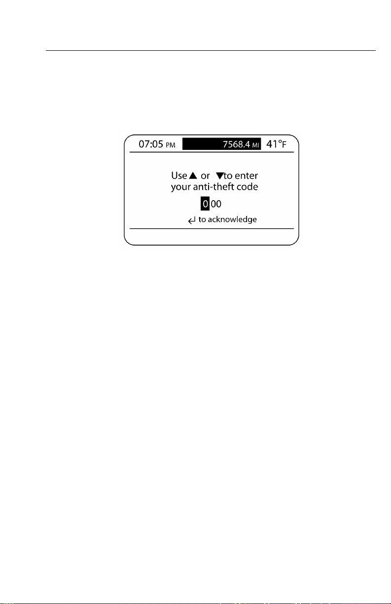
V-MACCo-PilotOperator’sManual75
TheftDeterrent
TheTHEFTDETERRENTscreen,ifprogrammed,willappearaftertheMACK
LOGOINTROscreen.Messagespromptthedrivertoenterapassword.Ifanincorrect
passwordisenteredafterapredeterminednumberofattempts,accessisdeniedandthe
vehiclewillshutdownandnotallowenginestartuntilthecorrectpasswordisentered.
W3036585
Figure39—TheftDeterrentScreen
Page 83
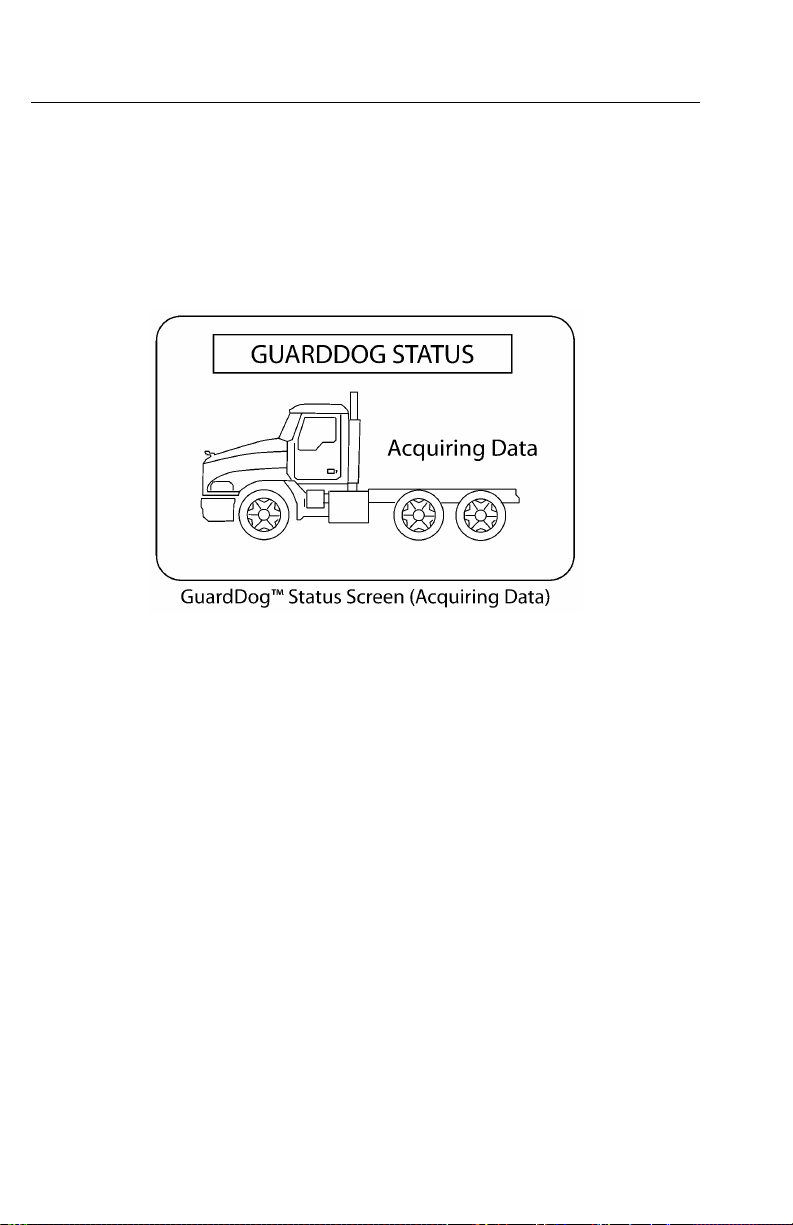
76V-MACCo-PilotOperator’sManual
GuardDog™Status
TheGUARDDOG™STA TUSscreen,ifequipped,willappearaftertheMACK
LOGOINTROscreenandtheTHEFTDETERRENTscreen(ifprogrammed).The
screenwaitstoacquiredatafromthetruckandwilldisplaymaintenanceitems
needingservice.FormoreGuardDog™screens,pleaserefertothe“CO-PILOT®
STATIONARYSCREENS”,page85and“CO-PILOT®INTERRUPTSCREENS”,
page93.
C0035383
Figure40—GuardDogStatusScreen(AcquiringData)
CurrentConditions
TheCURRENTCONDITIONSscreenwillappearaftertheMACKLOGOINTRO
screenoraftertheTHEFTDETERRENTandGUARDDOGST A TUSINTROscreens
(ifequippedandprogrammed).Whenthetruckisstationary,thetime,mileage,
outsidetemperatureandbatteryvoltagearedisplayed.Whenthevehicleismoving,in
additiontotheaboveitems,sweetspotinformation(whentheengineisbeingoperated
atitsmostefcientrange),bonusorpenaltymode(alertsthedriverifvehiclespeed
andcruisemaximumspeedcanbeincreasedordecreasedforthebestfueleconomy),
andgearstatewillalsoappear.Theinformationareaofthisscreenwillremainblank
unlessaninterruptscreenappearsorthedriverstartsuptheCo-Pilotmainmenu.
Note:TheappearanceoftheGEAR
indicator(see)isonlydisplayedwithan
automatedmanualtransmission.
Page 84
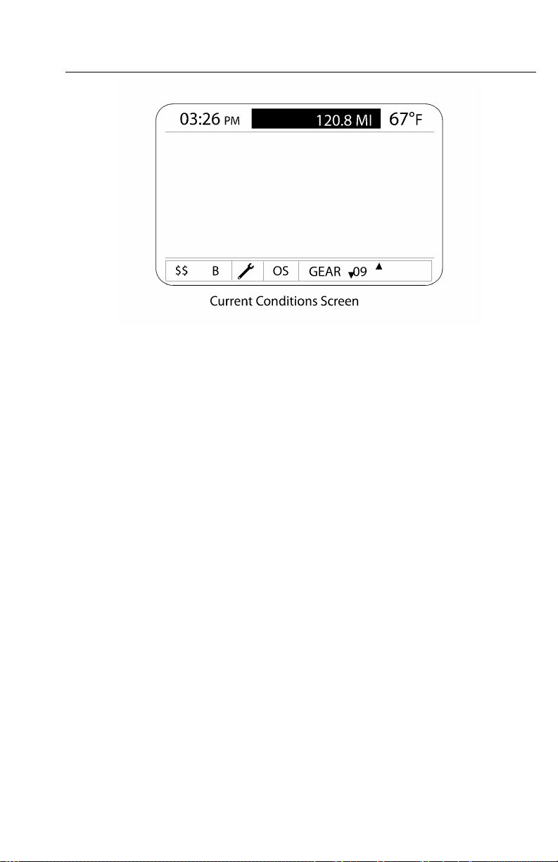
V-MACCo-PilotOperator’sManual77
W3036586
Figure41—CurrentConditionsScreen
Page 85
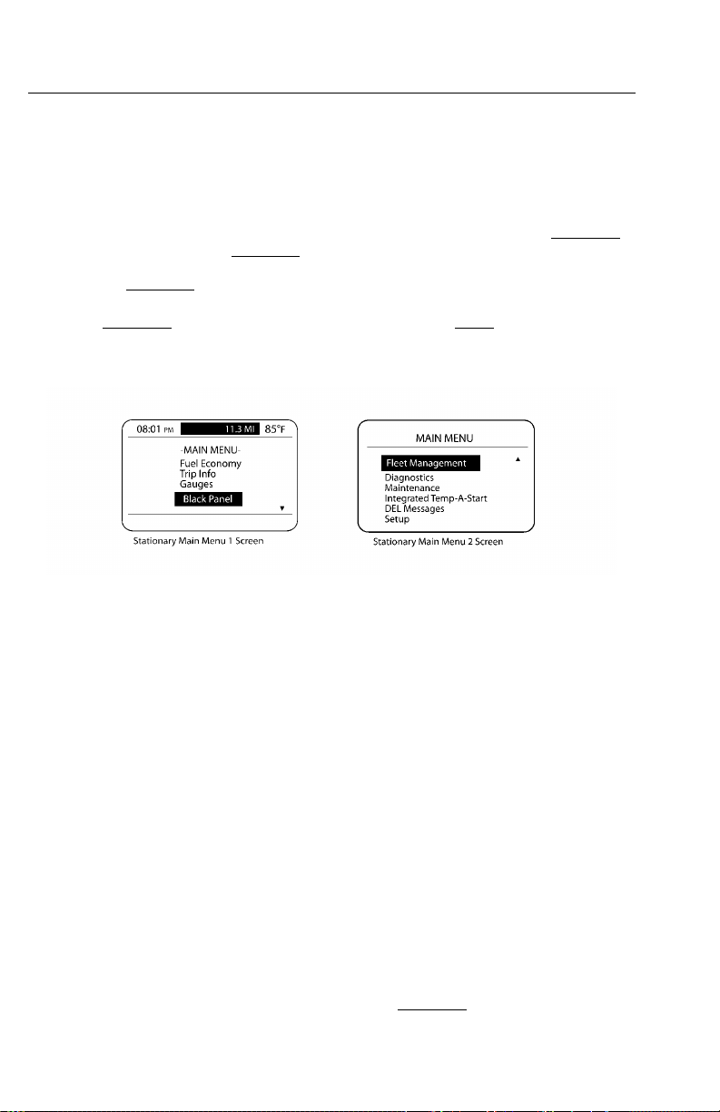
78V-MACCo-PilotOperator’sManual
CO-PILOT®MENUSCREENS
MainMenu—StationaryVehicle
TheMAINMENUscreenconsistsoftwoscreensforastationaryvehicle:stationary
MAINMENU1screenandstationaryMAINMENU2screen.
TocausethestationaryMAINMENU1screentoappear,pressandholdthestalk
switchEnter(↵ ↵↵)buttonwhenintheCURRENTCONDITIONSscreen(see).T o
causethestationaryMAINMENU2screentoappear,scrolldownonthestalkswitch
Up&Downbutton.
W3036587
Figure42—StationaryMainMenuScreens
Fromthesetwomenus,thedrivercanaccessthefollowinginformationsupplied
inasubmenustructure:
•FuelEconomy(AnytimeandStationaryScreens)
•TripInformation(AnytimeandStationaryScreens)
•Gauges(AnytimeandStationaryScreens)
•FleetManagement(StationaryScreens)
•Diagnostics(StationaryScreens)
•Maintenance(StationaryScreens)
•IntegratedTemp-A-Start(ifavailable;forfuturesupport)
•DriverEventMessages(StationaryScreens)
•Settings(StationaryScreens)
Note:ToviewanyoftheabovesubmenusfromthestationaryMainMenuscreens,
usethestalkswitchUp&Downbuttontohighlightanitemandthenpressthestalk
switchEnter(↵ ↵↵)buttontomakeyourselection.
Page 86
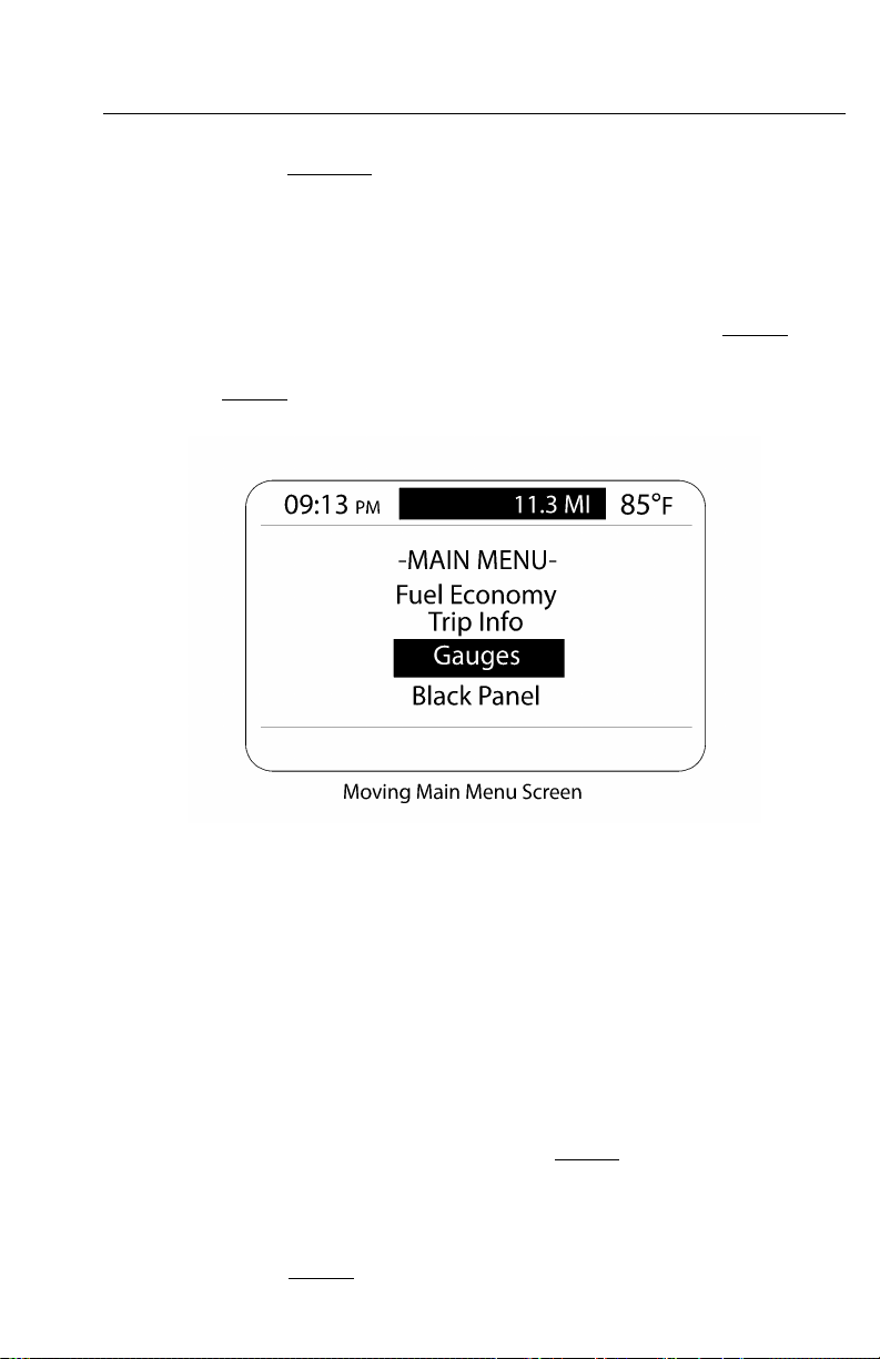
V-MACCo-PilotOperator’sManual79
AlsoincludedinthestationaryMAINMENU1istheselectionofablack-outpanel.
Detailedinformationonthesesubmenusandtheirscreensisavailableinand.
MainMenu—MovingVehicle
TheMAINMENUscreenconsistsofonescreenforamovingvehicle:moving
MAINMENUscreen.
TocausethemovingMAINMENUscreentoappear,pressthestalkswitchEnter(↵ ↵
)buttonwhenintheCURRENTCONDITIONSscreen(see).
W3036590
Figure43—MovingMainMenuScreen
Fromthismenu,thedrivercanaccessthefollowinginformationsuppliedina
submenustructure:
•FuelEconomy(AnytimeandStationaryScreens)
•TripInformation(AnytimeandStationaryScreens)
•Gauges(AnytimeandStationaryScreens)
↵
Note:ToviewanyoftheabovesubmenusfromthemovingMainMenuscreen,use
thestalkswitchUp&Downbuttontohighlightanitemandthenpressthestalkswitch
Enter(↵ ↵↵)buttontomakeyourselection.
AlsoincludedinthemovingMAINMENUscreenistheselectionofablack-out
panel.Detailedinformationonthesesubmenusandtheirscreensisavailablein
Page 87

80V-MACCo-PilotOperator’sManual
CO-PILOT®ANYTIMESCREENS
Co-Pilot®Anytimescreensincludethefollowingmainscreens:
•FuelEconomy
•TripInformation
•DigitalGauges
•BlackPanel
Tonavigatethroughthescreens,rememberthefollowing:
•UsethestalkswitchUp&Downbuttontoscrollandhighlightanitem,scrollto
thenextscreen,orenteravalue.
•UsetheEnter(↵ ↵
returntothepreviousscreen.
↵
)buttontoselectascreen,enteravalue,acceptachangeor
•UsetheESCbuttontoreturntothepreviousscreen.
FuelEconomy
TheFUELECONOMYsubmenuscreenisdisplayedbyselectingFuelEconomyfrom
themovingMAINMENUscreen(see)orfromthestationaryMAINMENU1screen
(see)andpresstheEnter(↵ ↵↵)button.Thesescreensshowthecurrent“trip”average
fueleconomy ,the“instantaneous”fueleconomyonthescaleandthe“Bonus”and
“Penalty”incentivemodes(onlywhenequippedwiththisfeature).
Figure44—FuelEconomyScreens
W3036612
Page 88

V-MACCo-PilotOperator’sManual81
TripInformation
•TheTRIPINFORMA TIONsubmenuscreenisdisplayedbyselectingT ripInfo
fromthemovingMAINMENUscreen(see)orfromthestationaryMAINMENU
1screen(see)andthenpressingtheEnter(↵ ↵↵)button.
W3036614
Figure45—T ripInformationScreens
TheTRIPINFORMA TIONsubmenuscreencontainsthefollowingscreens:
•DriverTrip1andDriverT rip2—Displaysinformationsuchasdateandtime,
distance,maximumRPMandmi/h,averagemi/handMPG,idletime,cruisetime
andtimespentin“sweetspot,”enginebraketimeandpowertakeoff(PTO)time.
Thesescreensalsoallowthecurrentdrivertripinformationtoberesetifdesired,
ortosuspendandactivateacurrentdrivertrip.
Whentwodriversaredrivingascheduledtrip,anddriver1hascompletedthe
tripsegment,theDriverTrip1segmentmustbeended.Toendthetrip,therst
drivershouldselect“SuspendOK”fromtheDriverTrip1screen(see).When
Driver2isreadytobeginhistripsegment,heshouldselect“ActivateOK”from
theDriverTrip2screen(see).
•FleetTrip—Displaystripnumber,driverID,BillofLadingnumber,startdate
andtime,totaldateandtime,totaldistanceandfuel,maximumRPMandmi/h,
averagemi/handMPG,idletime,cruisetimeandtimespentin“sweetspot,”
enginebraketimeandPTOtime.
•LifeofVehicle(LOV)TripSummary—Displaysthelifeofvehicletrip
information.
•TotalEngineHours—Displaysthetotalenginehoursforthevehicle.
Page 89

82V-MACCo-PilotOperator’sManual
ThefollowingtabledisplaystheavailableLOVtripinformation.
AverageFuelEconomyPTOTime
AverageVehicleSpeedSweetSpotTime
CruiseTimeTotalFuelUsed
EngineBrakeTimeV ehicleHighestSpeed
EngineHighestRPMVehicleTime
IdleTimeTotalTime
W3036620
Figure46—TripInfoScreens
Page 90

V-MACCo-PilotOperator’sManual83
Gauges
TheGAUGESsubmenuscreen,selectedfromthemovingMAINMENUscreen
(see)orfromthestationaryMAINMENU1screen(see)providesthespeedometer
valueandsensorinformation.ToviewthescreensoftheGaugessubmenu,highlight
“Gauges”withthestalkswitchUp&DownbuttonandthenpresstheEnter(↵ ↵↵)
buttontoselectthescreen.
TheGAUGESsubmenuscreencontainsthefollowingscreens:
W3036622
Figure47—ViewGaugesScreens
•Speedometer—Allowstheusertoviewthecurrentspeedometervalue.
•ViewTempGauges—Displaysenginecoolanttemperature(ECT),engine
oiltemperature(EOT),engineexhaustgastemperature(EGT),transmission
oiltemperature,rearfrontaxletemperature,andrearaxletemperaturesensor
information.
•ViewPressureGauges—Displaysengineoilpressure(EOP),intakemanifold
pressure(IMP),andairsuspensionpressuresensorinformation.
•ViewOtherGauges—DisplaysengineRPM,engineloadpercentandthrottle
positionpercentsensorinformation.
Page 91
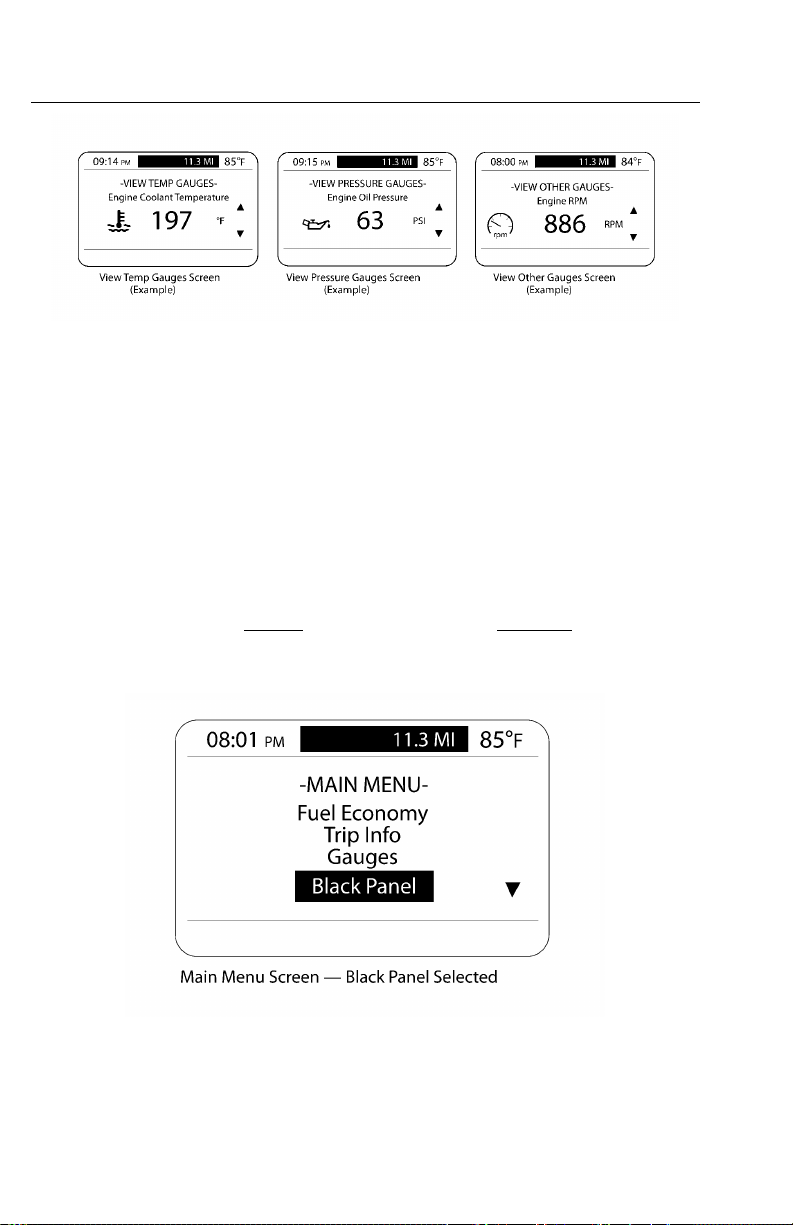
84V-MACCo-PilotOperator’sManual
W3036624
Figure48—ViewGaugesScreens
Note:Sensorsthatarenotstandardandhavenotbeenorderedwillnotappearonthe
screens.
BlackPanel
•TheBLACKPANELscreenisusedtoblackouttheCo-Pilot®display.Highlight
“BlackPanel”fromthemovingMAINMENUscreenorstationaryMAINMENU
1screen,andthenpressthestalkswitchEnter(↵ ↵↵)buttontoselectit.
•TorestoretheCo-Pilot®display,presstheEnter(↵ ↵
↵
)buttonagain.
Figure49—BlackPanelSelected
W3036626
Page 92

V-MACCo-PilotOperator’sManual85
CO-PILOT®STATIONARYSCREENS
Co-Pilot®Stationaryscreensincludethefollowingmainscreens:
•FuelEconomy(see)
•TripInformation(see)
•DigitalGauges(see)
•BlackPanel(see)
•FleetManagement
•Diagnostics
•Maintenance(ifavailable)
•DEL(DriverEventLogging)Messages
•SetUp(Display)
•IntegratedTemp-A-Start(ifavailable;forfuturesupport).See.
Tonavigatethroughthescreens,rememberthefollowing:
•UsethestalkswitchUp&Downbuttontoscrollandhighlightanitem,scrollto
thenextscreen,orenteravalue.
•UsetheEnter(↵ ↵
returntothepreviousscreen.
↵
)buttontoselectascreen,enteravalue,acceptachangeor
•UsetheESCbuttontoreturntothepreviousscreen.
FleetManagement
•TheFLEETMANAGEMENTsubmenuscreenisaccessedfromthestationary
MAINMENU2screen(see).T oviewthescreensoftheFLEETMANAGEMENT
submenu,highlight“FleetManagement”withthestalkswitchUp&Downbutton
andthenpresstheEnter(↵ ↵↵)buttontoselectthescreen.
Page 93

86V-MACCo-PilotOperator’sManual
TheFLEETMANAGEMENTsubmenuscreencontainsthefollowingmainscreens:
•ChangeDriver—Allowstheusertochangedrivers.Therearethreewaysto
changedriverentries:
1EnterdriverIDusingthestalkswitchUp&Downbuttontotypeinthedriver
identicationnumber.
2PickanIDfromthelistusingthestalkswitchUp&Downbutton.
3EnterthetheftIDusingthestalkswitchUp&Downbutton.
•NextFleetTrip—Allowstheusertoadvancetothenexteettrip.
•NextFleetT ripNewDriver—Allowstheusertoadvancetothenexttripand
newdriver.
•BillofLading—AllowsthedrivertoentertheBillofLadingnumber.
C0035398
Figure50—FleetMgmtSubmenuScreens
Diagnostics
TheDiagnosticssubmenuscreenisaccessedfromthestationaryMAINMENU2
(see).ToviewthescreensoftheDIAGNOSTICSsubmenu,highlight“Diagnostics”
withthestalkswitchUp&DownbuttonandthenpresstheEnter(↵ ↵
selectthescreen.
TheDIAGNOSTICSsubmenuscreencontainsthefollowingmainscreens:
↵
)buttonto
•ElectronicFaults—Allowstheusertoviewactiveandinactivediagnostic
troublecodes(DTCs)aswellasclearinactiveDTCsaccordingtothecontrolling
ECUandotherDTCidentiers.
•ClusterDiagnostics—Allowstheusertotestbulbs,pointersongauges,graphics
andalarmsassociatedwiththecluster.
•Hardware/SoftwarePartNumbers—Allowstheusertoviewthehardwareand
softwarepartnumbersoftheenginecontrolmodule(ECM),anti-lockbraking
system(ABS)electroniccontrolunit(ECU),instrumentclusterandvehicleECU.
Page 94

V-MACCo-PilotOperator’sManual87
C0035399
Figure51—DiagnosticsSubmenuScreens
W3036629
Figure52—DiagnosticsSubmenuScreens
Page 95

88V-MACCo-PilotOperator’sManual
Maintenance
TheMAINTENANCEsubmenuscreenisaccessedfromthestationaryMAINMENU
2screen(see).ToviewthescreensoftheMAINTENANCEsubmenu,highlight
“Maintenance”withthestalkswitchUp&DownbuttonandthenpresstheEnter
(↵ ↵↵)buttontoselectthescreen.
TheMAINTENANCEsubmenuscreencontainsthefollowingmainscreens:
Displaysthemaintenancescheduleforvariousmaintenanceitems,suchasengineoil
andcoolantchange.Maintenanceitemsaredisplayedonthescreenoneatatime
asshownin.Maintenanceitems,whenenabledinVCADSorMACKtraq,canbe
resetaftermaintenancehasbeenperformed.Ifmaintenancehasnotbeenperformed,
resettingthemaintenanceitemwillbeprohibited.
MaintenanceMonitor
C0035402
Figure53—MaintenanceScreens
GuardDog™(optional;mustbeenabled)
GuardDog™,anactivemaintenancemonitoringsystem,usessensorreadingstoshow
thestatusofroutinemaintenancerequirements.Ifthevehicleisequippedwiththe
GuardDog™system,Co-PilotwilldisplayGuardDog™relatedmaintenanceitems
underthefollowingconditions:
•Whenthevehicleisstarted
•Duringdrivingasindividualmaintenanceitemsbecomedue
•ManuallythroughtheGuardDog™Statusscreen
Afterpower-upinitiationandtheMACKLOGOscreenappearance,theCo-Pilot
willdisplaytheACQUIRINGDATAscreen.Afteractivationonthisscreen,ifno
maintenanceitemisdue,theGUARDDOG™NOMAINTENANCEITEMSDUE
screenwillappear.However,ifmorethanonemaintenanceitemrequiresservice,the
GUARDDOG™MAINTENANCEinterruptscreen(see)willappear.Toviewthe
duemaintenanceitems,selecttheGUARDDOG™STA TUSscreen.
Page 96
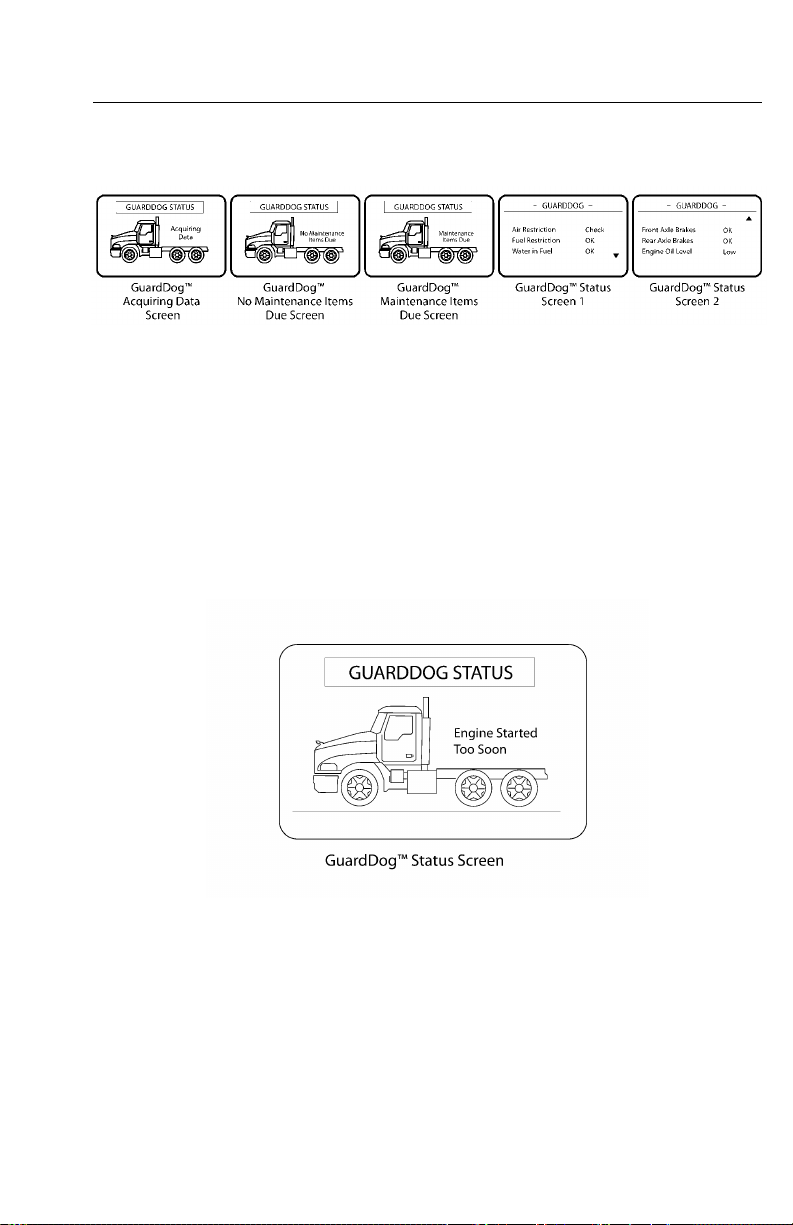
V-MACCo-PilotOperator’sManual89
TheGUARDDOG™STATUSscreenwilldisplayalistofGuardDog™itemsandthe
correspondingconditionwillbeshownas“low,”“check,”or“OK.”
C0035403
Figure54—GuardDog™MaintenanceScreens
Note:Theoillevelindicatortakes
between15and20secondstoprovide
data.Iftheengineisstartedwithinthis
timeperiodwithnovalidoillevelreading,
theCo-Pilotwilldisplaythemessage,
“Unabletoobtaintheoilleveldata.
Enginestartedtoosoon.”
Figure55—GuardDogStatusScreen
Note:IfGuardDog™isnotinstalled,
allGuardDog™menuselectionswillbe
unavailable.
W3036651
Page 97
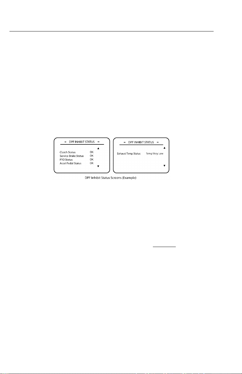
90V-MACCo-PilotOperator’sManual
Water-in-Fuel(WIF)[ifequipped]
Allowstheusertosenda“drainwater”commandtotheEMSmodule.IftheWater
inFuelsensordetectsliquidinthewater-separatorbowl,theWIFindicatoronthe
instrumentclusterwillilluminatetonotifythedriver.
DPFInhibitStatus
Indicateswhytheaftertreatmentdieselparticulatelter(DPF)regenerationwas
notstarted.ToviewtheDPFInhibitStatuslistintheMAINTENANCEsubmenu,
highlight“DPFInhibitStatus”withthestalkswitchUp&Downbuttonandthepress
theEnter(↵ ↵↵)buttontoview.
C0035430
Figure56—DPFInhibitStatusScreen
DELMessages
TheDELMESSAGESsubmenuscreenisaccessedfromthestationaryMAINMENU
2screen(see).TheDELMESSAGESsubmenucontainsalistofdrivereventlogging
messages.Adrivermaychoosetologadrivereventloggingmessagedependingon
thedriver’sactivity.Forexample,ifthedriverisgoingtoleaveaterminal,thedriver
wouldselecttheLEA VETERMINALmessage.
ToviewthelistofdrivereventloggingmessagesintheDELMESSAGESsubmenu,
highlight“Messages”withthestalkswitchUp&Downbuttonandthenpressthe
Enter(↵ ↵↵)buttontoselectthemessagetolog.
Note:TheDELMESSAGESsubmenuis
optionalandwillonlyappearifenabledin
VCADSsoftwareorMACKtraq.
Page 98
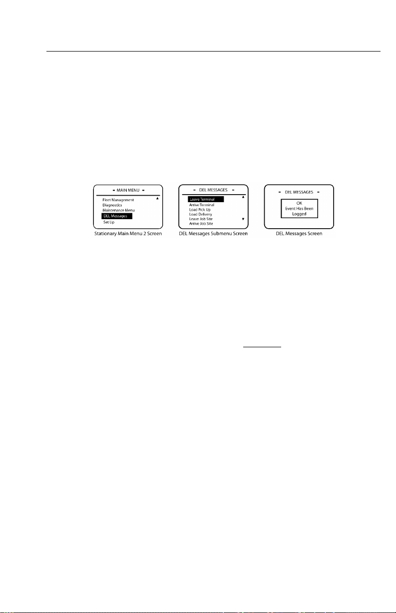
V-MACCo-PilotOperator’sManual91
TheDELMESSAGESsubmenucontainsthefollowingdrivereventlogging
messages:
•LeaveTerminal
•ArriveTerminal
•LoadPickUp
•LoadDelivery
•LeaveJobSite
•ArriveJobSite
Figure57—DELMessagesScreens
SetUp
C0035404
TheSETUPsubmenuscreenisaccessedfromthestationaryMAINMENU2screen
(see).
ToviewtheSETUPsubmenu,highlight“SetUp”withthestalkswitchUp&Down
buttonandthenpresstheEnter(↵ ↵↵)buttontoselectthescreen.
TheSETUPsubmenuscreencontainsthefollowingmainscreens:
•Language—Permitstheusertochangelanguageselections.Thedefaultsettingis
English.
•Units—Allowstheusertochangetheunitofmeasurefortemperature,distance,
fuel,andpressure.
•DriverOverSpeedAlarm(ifavailableandforfuturesupport)—Allowstheuser
todesignateapersonalspeedlimit.Ifthisspeedisexceeded,analarmwillsound
andanOverspeedwarninginterruptscreenwillappeartowarnthedriver.
•DateandTime—Permitstheusertosettimeanddate,decidetousea12houror
24hourclockdisplayandtocongurethewaythedatewilldisplay(i.e.,days,
months,years).
•DisplayLight—AllowstheusertomodifythepaneldisplayoftheCo-Pilot.
Page 99
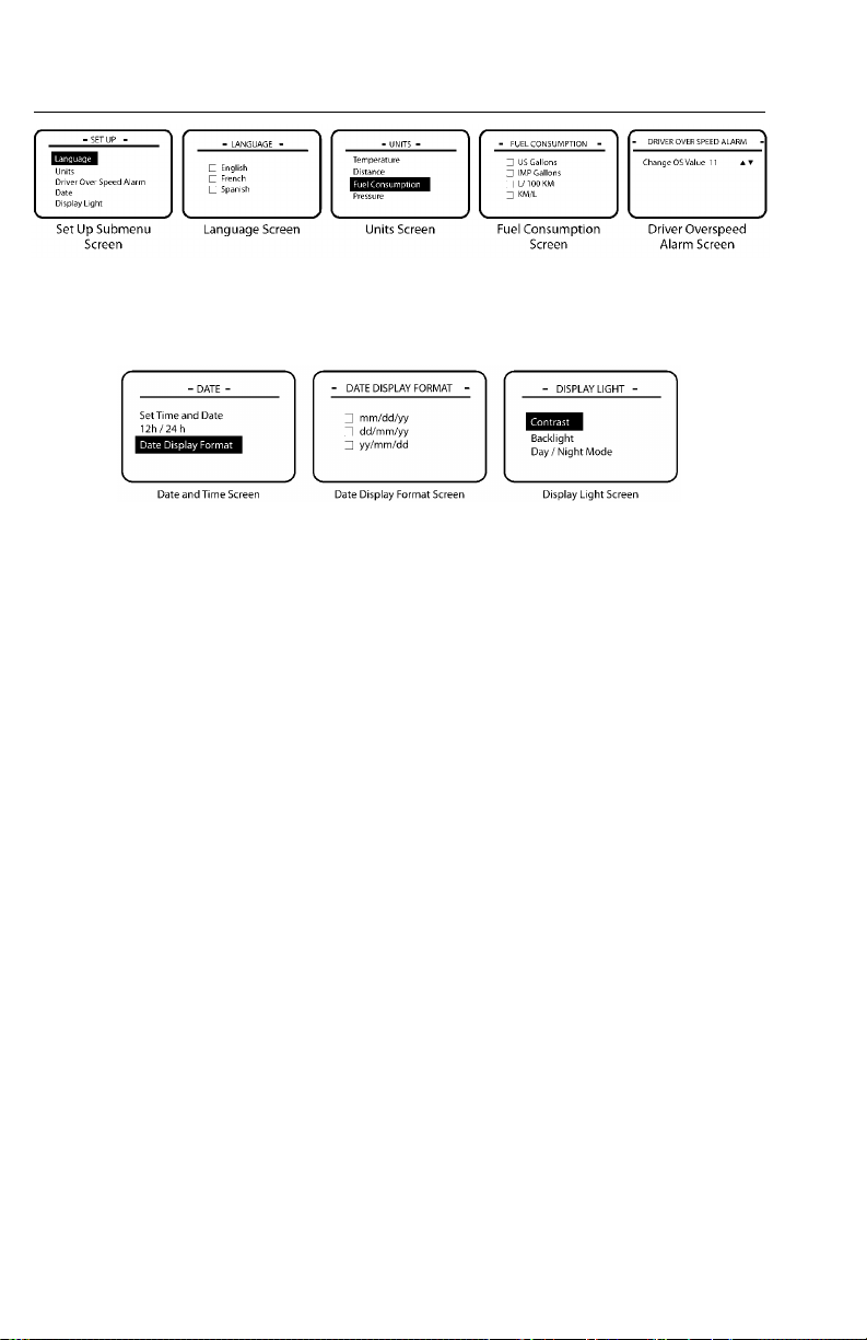
92V-MACCo-PilotOperator’sManual
Figure58—SetUpSubmenuScreens
Figure59—SetUpSubmenuScreens
C0035405
C0035406
Page 100
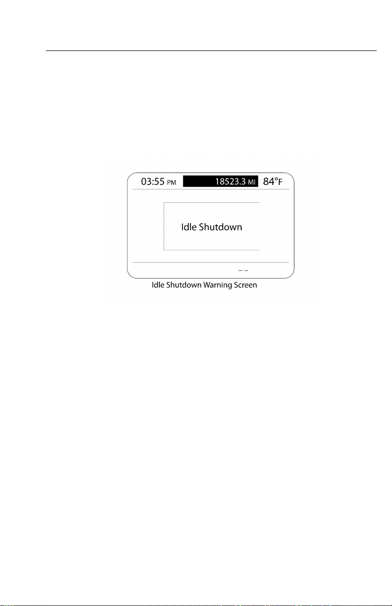
V-MACCo-PilotOperator’sManual93
CO-PILOT®INTERRUPTSCREENS
IdleShutdownWarning
TheIDLESHUTDOWNW ARNINGscreendisplaysatimerwarningandanalarm
soundstoinformthedriverthatthevehicleisgoingtoshutdownuntilthecondition
goesawayorthedriveracknowledgesthewarningbypressingtheEnter(↵ ↵↵)button.
W3036652
Figure60—IdleShutdownWarningScreen
DriverOverspeedWarning(ifAvailable)
TheDRIVEROVERSPEEDW ARNINGscreenappearsandanalarmsoundswhen
thedriverexceedsaspeedthreshold.Thisscreenisdisplayeduntilthedriver
acknowledgesthewarningandalarmbypressingtheEnter(↵ ↵↵)buttonordecelerates
belowthethreshold.Thealarmwillsoundagainifthethresholdisexceeded.
 Loading...