


Simply Connected
User Guide
XMS-1024P
24 Port Gigabit Managed
PoE/PoE+ Switch
Use the XMS-1024P to:
Cost-effectively Add 802.3af/at PoE Capability to Your Network
Deliver Power and Data for up to 24 PoE-Enabled Network Devices with a Maximum Output of 320 Watts
Simplify PoE Device Installation, Including IP Sercurity Cameras, VoIP Devices, and Wireless AP’s
Future Proof Your Network with Gigabit Speeds (10X Performance of Fast Ethernet)
Optimize and Protect Your Network with Advanced VLAN, QoS and Network Security Features
XMS-1024P
User Guide
Model Number: XMS-1024P
24 Port Gigabit Managed PoE/PoE+ Switch
© 2014 Luxul. All Rights Reserved.
No part of this publication may be modified or adapted in any way, for any purposes without permission in writing from Luxul. The material in this manual is subject to change without notice. Luxul reserves the right to make changes to any product to improve reliability, function, or design. No license is granted, either expressly or by implication or otherwise under any Luxul intellectual property rights. An implied license only exists for equipment, circuits and subsystems contained in this or any Luxul product.
This product is covered by one or more U.S. and foreign patents.
Patents: 7,379,717, 6,606,075, 6,373,448, other patents pending
DOCUMENT CONVENTIONS
The following graphical alerts are used in this document to indicate notable situations:
 NOTE: Tips, hints, or special requirements that you should take note of.
CAUTION: Care is required. Disregarding a caution can result in data loss or equipment malfunction.
WARNING!: Indicates a condition or procedure that could result in personal injury or equipment damage.
CONTACT LUXUL
Sales |
Technical Support |
P: 801-822-5450 |
P: 801-822-5450 |
E: sales@luxul.com |
E: support@luxul.com |
FCC COMPLIANCE
This device complies with Part 15 of the FCC Rules. Operation is subject to the following two conditions: (1) this device may not cause harmful interference, and
(2) this device must accept any interference received, including interference that may cause undesired operation.
2 |
a: 14203 Minuteman Drive, Suite 201, Draper, UT 84020-1685 | luxul.com | 801-822-5450 |
|
LUX-UG-XMS-1024P Vers: 081314 |
||
|

|
User Guide |
CONTENTS |
|
1 ABOUT THIS GUIDE |
6 |
1.1 Intended Readers |
6 |
1.2 Conventions |
6 |
1.3 Overview of This Guide |
6 |
2 INTRODUCTION |
10 |
2.1 Overview of the Switch |
10 |
2.2 Main Features |
11 |
2.3 Description |
12 |
3 LOGGING ON TO THE SWITCH |
14 |
3.1 Login |
14 |
3.2 Configuration |
15 |
4 SYSTEM |
16 |
4.1 System Settings |
16 |
4.2 User Management |
24 |
4.3 System Tools |
26 |
5 SWITCHING |
38 |
5.1 Port Settings |
38 |
5.2 LAG |
48 |
5.3 Traffic Monitor |
53 |
5.4 MAC Address |
57 |
6 VLAN |
64 |
6.1 802.1Q VLAN |
66 |
6.2 MAC VLAN |
72 |
6.3 Protocol VLAN |
74 |
6.4 Application Example for 802.1Q VLAN |
81 |
6.5 Application Example for MAC VLAN |
82 |
6.6 Application Example for Protocol VLAN |
84 |
6.7 GVRP |
86 |
7 SPANNING TREE |
90 |
7.1 STP Config |
97 |
7.2 Port Config |
100 |
7.3 MSTP Instance |
102 |
7.4 STP Security |
107 |
© 2014 Luxul. All Rights Reserved. |
3 |
|
Other trademarks and registered trademarks are the property of their respective owners |
||
|

XMS-1024P
7.5 Application Example for STP Function |
111 |
8 MULTICAST |
116 |
8.1 IGMP Snooping |
119 |
8.2 Multicast IP |
130 |
8.3 Multicast Filter |
132 |
8.4 Packet Statistics |
135 |
9 QOS |
137 |
9.1 DiffServ |
141 |
9.2 Bandwidth Control |
147 |
9.3 Voice VLAN |
151 |
10 POE |
157 |
10.1 PoE Config |
158 |
10.2 PoE Time-Range |
161 |
11 ACL |
165 |
11.1 Time-Range |
165 |
11.2 ACL Config |
169 |
11.3 ACL Policy |
176 |
12 NETWORK SECURITY |
186 |
12.1 IP-MAC Binding |
186 |
12.2 ARP Inspection |
199 |
12.3 DoS Defense |
207 |
12.4 802.1X/RADIUS |
209 |
13 SNMP |
220 |
13.1 SNMP Config |
223 |
13.2 SNMP Notification |
232 |
13.3 RMON |
234 |
14 LLDP |
239 |
14.1 LLDP Config |
244 |
14.2 Device Info |
246 |
14.3 Device Statistics |
249 |
14.4 LLDP-Media |
250 |
15 CLUSTER |
257 |
15.1 NDP |
259 |
15.2 NTDP |
263 |
4 |
a: 14203 Minuteman Drive, Suite 201, Draper, UT 84020-1685 | luxul.com | 801-822-5450 |
|
LUX-UG-XMS-1024P Vers: 081314 |
||
|

|
User Guide |
15.3 Cluster |
269 |
16 MAINTENANCE |
271 |
16.1 System Monitor |
271 |
16.2 System Logs |
273 |
16.3 Device Diagnostics |
279 |
16.4 Network Diagnostics |
281 |
17 SAVE CONFIG |
282 |
18 REGULATORY COMPLIANCE |
283 |
APPENDIX A: SPECIFICATIONS |
286 |
GLOSSARY |
287 |
© 2014 Luxul. All Rights Reserved. |
5 |
|
Other trademarks and registered trademarks are the property of their respective owners |
||
|

XMS-1024P
1 ABOUT THIS GUIDE
This User Guide contains information for setup and Management of the XMS-1024P 24 Port Gigabit Managed PoE/PoE+ Switch. Please read this guide carefully.
1.1 Intended Readers
This Guide is intended for users or installers familiar with IP concepts and Network terminologies.
1.2 Conventions
In this Guide the following conventions are used:
The Switch mentioned in this Guide refers to the XMS-1024P Managed PoE Switch
Menu Name>>Submenu Name>>Tab indicates the location being illustrated in the menu structure. (i.e. System>>System Settings>>Status is the Status tab under the System Settings menu option that is located under the System menu).
Bold font indicates a button, a toolbar icon, menu or menu item.
1.3 Overview of This Guide
Chapter |
Introduction |
Chapter 1 About This Guide |
Introduces the guide structure and conventions. |
Chapter 2 Introduction |
Introduces the features, application and appearance of |
|
XMS-1024P Switch. |
Chapter 3 Login |
Illustrates how to log on to the Web Management page. |
Chapter 4 System |
This chapter will show how to configure system properties |
|
of the Switch. |
|
System Settings: Configure the Description, System |
|
Time and Network parameters of the Switch. |
|
User Management: Configure the User Name and |
|
Password for users to log on to the Web Management |
|
page with the desired level of access. |
|
System Tools: Manage the Configuration File of |
|
the Switch. |
|
Access Control: Provide different security measures for |
|
login to enhance Configuration Security. |
6 |
a: 14203 Minuteman Drive, Suite 201, Draper, UT 84020-1685 | luxul.com | 801-822-5450 |
|
LUX-UG-XMS-1024P Vers: 081314 |
||
|

|
User Guide |
Chapter |
Introduction |
Chapter 5 Switching |
This chapter will show how to configure basic functions |
|
of the Switch. |
|
Port: Configure the basic features of the Switch Ports. |
|
LAG: Configure Link Aggregation Group. A LAG |
|
combines a number of Ports together to make a single |
|
high-bandwidth Data path. |
|
Traffic Monitor: Monitor the traffic statistics of |
|
each Port |
|
MAC Address: Modify the MAC MAC Table properties |
|
of the Switch. |
Chapter 6 VLAN |
This chapter will show how to configure VLANs to control |
|
broadcast on the Local Area Network. |
|
802.1Q VLAN: Configure an 802.1Q VLAN on a Port-per- |
|
Port basis. |
|
MAC VLAN: Configure 802.1 Q MAC-based VLAN |
|
without changing the 802.1Q VLAN configuration. |
|
Protocol VLAN: Create VLANs using the application |
|
layer to adjust how some Data is transmitted in the |
|
specified VLAN. |
|
GVRP: GVRP allows the Switch to automatically add |
|
or remove VLAN membership via dynamic VLAN |
|
registration information and propagate the local VLAN |
|
registration information to other Switches, without |
|
having to individually configure each VLAN on |
|
every Switch. |
Chapter 7 Spanning Tree |
This chapter will show how to configure Spanning Tree |
|
functions on the Switch. |
|
STP Config: Configure and view the global settings of |
|
Spanning Tree. |
|
Port STP Config: Configure the STP parameters of |
|
Switch Ports. |
|
MSTP Instance: Configure MSTP instances. |
|
STP Security: Configure STP protection to prevent |
|
devices from any malicious attack against STP. |
© 2014 Luxul. All Rights Reserved. |
7 |
|
Other trademarks and registered trademarks are the property of their respective owners |
||
|

XMS-1024P
Chapter |
Introduction |
Chapter 8 Multicast |
This chapter will show how to configure the Multicast |
|
functions of the Switch. |
|
IGMP Snooping: Configure global parameters of IGMP |
|
Snooping, Port properties, VLAN, and Multicast VLAN. |
|
Multicast IP: Configure Multicast IP table. |
|
Multicast Filter: Configure Multicast Filter to restrict |
|
users ordering Multicast programs. |
|
Packet Statistics: View the Multicast traffic statistics on |
|
each Port of the Switch. |
Chapter 9 QoS |
This chapter will show how to configure QoS to provide |
|
the desired quality of service for various Network |
|
applications and requirements |
|
DiffServ: Configure priorities, Port priority, 802.1P |
|
Priority and DSCP priority. |
|
Bandwidth Control: Rate Limit feature to control the |
|
traffic rate on each Port; Storm Control feature to filter |
|
Broadcast, Multicast and UL frames in the Network. |
|
Voice VLAN: Voice VLAN to transmit Voice Data stream |
|
within the specified VLAN to ensure the transmission |
|
priority of Voice Data stream and Voice quality. |
Chapter 10 PoE |
This chapter will show how to configure the PoE for the |
|
Switch to supply power for PoE capable devices. |
|
PoE Config: PoE global functionality. |
|
PoE Time-Range: Time window(s) for PoE Port to |
|
supply power. |
Chapter 11 ACL |
This chapter will show how to configure ACL Rules and |
|
Policies to filter packets in order to prevent malicious |
|
packets from harming the Network. |
|
Time-Range: The effective time for ACL Rules. |
|
ACL Config: ACL Rules. |
|
Policy Config: Policy operational parameters. |
|
Policy Binding: Bind the policy to a Port or VLAN. |
8 |
a: 14203 Minuteman Drive, Suite 201, Draper, UT 84020-1685 | luxul.com | 801-822-5450 |
|
LUX-UG-XMS-1024P Vers: 081314 |
||
|

|
User Guide |
Chapter |
Introduction |
Chapter 12 Network Security |
This Chapter will show how to configure the multiple |
|
protection measures in Network Security. |
|
IP-MAC Binding: Bind the IP Address, MAC address, |
|
VLAN ID and the Connected Port of the Host together. |
|
ARP Inspection: ARP Inspection feature prevent ARP |
|
attacks on the Network. |
|
DoS Defend: DoS Defense features to prevent |
|
DoS attack. |
|
802.1X/RADIUS: Covers the use of 802.1X/RADIUS and |
|
Radius Servers. |
Chapter 13 SNMP |
This chapter will show how to configure SNMP to provide |
|
a Management frame to monitor and maintain the |
|
Network devices. |
|
SNMP Config: Global settings of SNMP. |
|
SNMP Notification: SNMP Notification options and |
|
configuration for the to monitor and process the events. |
|
RMON: RMON (Remote Monitoring) options and |
|
configuration. |
Chapter 14 LLDP |
This chapter will show how to configure LLDP to provide |
|
information for SNMP applications. |
|
Basic Config: The LLDP parameters of the device. |
|
Device Info: View the LLDP information of the local |
|
device and its neighbors |
|
Device Statistics: View the LLDP statistics of the |
|
local device |
|
LLDP-MED: Configure LLDP-MED parameters of |
|
the device. |
Chapter 15 Cluster |
This chapter will show how to configure the Cluster |
|
function to allow central Management of devices in |
|
the Network. |
|
NDP: NDP setup to get the information from the |
|
directly connected neighbor devices. |
|
NTDP: NTDP functions of the commander Switch to |
|
collect NDP information. |
|
Cluster: Cluster setup to establish and maintain |
|
the Cluster. |
© 2014 Luxul. All Rights Reserved. |
9 |
|
Other trademarks and registered trademarks are the property of their respective owners |
||
|

XMS-1024P
Chapter |
Introduction |
Chapter 16 Maintenance |
This chapter will show how to use the common system |
|
tools to manage the Switch. |
|
System Monitor: The memory and CPU usage of |
|
the Switch. |
|
Log: View system events. |
|
Device Diagnostics: Test the connection status of the |
|
cable connected to the Switch. |
|
Network Diagnostics: Ping and Traceroute utilities to |
|
test connection at the Switch. |
Appendix A Specifications |
Lists the hardware specifications of the Switch. |
Appendix B Configure the PCs |
Introduces how to configure the PCs. |
Appendix C Load Software |
Introduces how to load software of the Switch using |
Using FTP |
FTP function. |
Appendix D 802.1X/RADIUS |
Introduces how to use 802.1X/RADIUS Client Software |
Client Software |
provided for Authentication. |
Appendix E Glossary |
The glossary of the manual.z |
2 INTRODUCTION
Thanks for choosing the Luxul XMS-1024P Managed PoE/PoE+ Switch
2.1 Overview of the Switch
Designed to meet Commercial Grade requirements, the XMS-1024P from LUXUL provides wire-speed performance and IP Layer 2 Management features to give you the best service and security available.
The EIA Standardized framework and smart configuration capacity provides a flexible solution for any scale of Network. ACL, 802.1X/RADIUS and Dynamic ARP Inspection provide robust security. QoS and IGMP Snooping/Filtering help optimize Voice and video applications. Link Aggregation (LACP) increases aggregated bandwidth, optimizing the transport of critical Data. SNMP, RMON, Web Management/CLI/Telnet Log-in options give you maximum Management flexibility. The XMS-1024P Managed PoE Switch is also a Power Source Equipment device. All the Auto-Negotiating RJ45 Ports on the Switch support Power over Ethernet, which can automatically detect and supply power to Powered Devices complying with the IEEE 802.3af and IEEE 802.3at standards.
10 |
a: 14203 Minuteman Drive, Suite 201, Draper, UT 84020-1685 | luxul.com | 801-822-5450 |
|
LUX-UG-XMS-1024P Vers: 081314 |
||
|
User Guide
2.2 Main Features
Resiliency and Availability
Link Aggregation (LACP) increases aggregated bandwidth, optimizing the transport of critical Data.
IEEE 802.1s Multiple Spanning Tree provides high link availability.
Multicast Snooping automatically prevents flooding of IP Network when using Multicast.
Layer 2 Switching
GVRP (GARP VLAN Registration Protocol) allows automatic learning and dynamic assignment of VLANs.
Supports up to 4094 VLANs.
Quality of Service
Supports L2 and L3 based CoS (Cost of Service) with 4 priority queues per Port.Rate Limiting controls the traffic flow according to the configured values.
Security
Supports industry standard user Authentication methods such as 802.1X/RADIUS, RADIUS.
Dynamic ARP Inspection blocks ARP packets from unauthorized hosts, preventing man-in-the-middle attacks.
L2/L3/L4 Access Control Lists restrict untrusted access to protected resources.Provides SSHv1/v2, SSL 2.0/3.0 and TLS v1 for Management access encryption.
Manageability
IP Clustering provides flexible scalability and easy Single-Switch-Management.
Telnet, CLI, SNMP v1/v2c/v3, RMON and Web Management access provides excellent Administration flexibility.
Port Mirroring enables monitoring of selected Ingress/Egress traffic.
© 2014 Luxul. All Rights Reserved. |
11 |
|
Other trademarks and registered trademarks are the property of their respective owners |
||
|
XMS-1024P
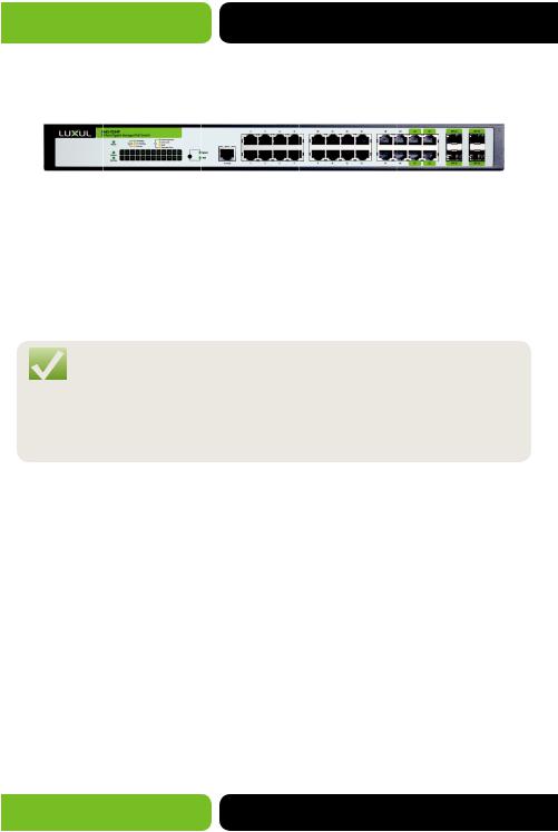
2.3 Description
2.3.1 Front Panel
Figure 2-1 Front Panel
The following parts are located on the front panel of the Switch:
24 10/100/1000Mbps Ports: Designed to connect client devices with a bandwidth of up to 1000Mbps.
4 SFP Ports: Designed to allow the use of an SFP module for fiber interlinking.
NOTE: When using the SFP Port with a 100Mbps module or a Gigabit module, you need to configure its corresponding Speed and Duplex mode in Switching>>Port Settings>>Port Config page. For 100Mbps module, please select 100MFD while selecting 1000MFD for Gigabit modules. By default, the Speed and Duplex mode of any installed SFP module is 1000MFD.
1 Console Port: Designed to allow connection to the serial Port of a computer or terminal for monitoring and configuring the Switch.
24 Port LEDs
The XMS-1024P has a LED mode button which is for Switching the LED status type. When the Speed LED is lit, the Port LED indicates link/link activity. When the PoE LED is lit, the Port LED indicates the power supply status. By default the Speed option is on. Pressing the Mode button will toggle between Speed and PoE. When selected, the PoE display will remain active for 60 seconds and then default back to Speed display.
When the Speed display is active, the Port LED will indicate the Link/Link Activity status of the Port.
12 |
a: 14203 Minuteman Drive, Suite 201, Draper, UT 84020-1685 | luxul.com | 801-822-5450 |
|
LUX-UG-XMS-1024P Vers: 081314 |
||
|
|
|
|
User Guide |
LED |
Status |
|
Indication |
Power |
On |
|
The Switch is powered on |
|
Off |
|
The Switch is powered off or power supply has failed |
|
Flashing |
|
Indicates a Power fault |
System |
Flashing |
|
The Switch booted without error and is running |
|
On |
|
The Switch encountered a boot error |
10/100/1000 |
Green |
On |
A 1000 Mbps device is connected to the |
Mbps Port LED |
|
|
corresponding Port |
|
|
Flashing |
Data is being transmitted or received on the |
|
|
|
corresponding Port |
|
Yellow |
On |
A 10/100 Mbps device is connected to the |
|
|
|
corresponding Port |
|
|
Flashing |
Data is being transmitted or received on the |
|
|
|
corresponding Port |
|
Off |
|
No device is connected to the corresponding Port |
When the PoE display is active, the Port LED indicates the PoE status of the Port.
LED |
Status |
|
Indication |
Power |
On |
|
The Switch is powered on |
|
Off |
|
The Switch is powered off or power supply has failed |
|
Flashing |
|
Indicates a Power fault |
System |
Flashing |
|
The Switch booted without error and is running |
|
On |
|
The Switch encountered a boot error |
PoE Max |
On |
|
The remaining PoE power available is ≤ 7W |
|
Flashing |
|
The remaining PoE power available stays at ≤ 7W the |
|
|
|
LED will remain on for 2 minutes |
|
Off |
|
The remaining PoE power available is > 7W |
10/100/1000 |
Green |
On |
The Port is supplying power normally |
Mbps Port LED |
|
Flashing |
The supply power exceeds the correspond PD’s |
|
|
||
|
|
|
(Powered Device) maximum power |
|
Yellow |
On |
Overload or short circuit is detected |
|
|
Flashing |
PD Power-On self-test has failed |
|
Off |
|
No PoE power is being provided on the Port |
© 2014 Luxul. All Rights Reserved. |
13 |
|
Other trademarks and registered trademarks are the property of their respective owners |
||
|
XMS-1024P
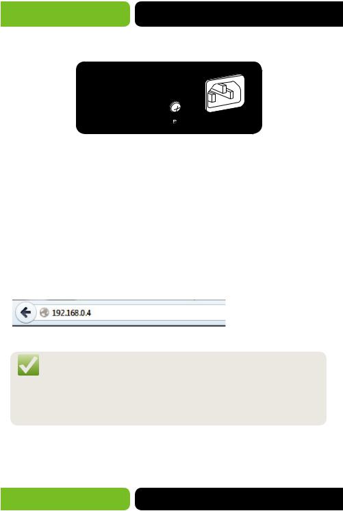
2.3.2 Rear Panel
The rear panel of XMS-1024P features a power socket and a Grounding Terminal.
|
-50/60Hz |
5.0A |
|
|
|
100 |
-240V |
|
|
|
Figure 2-2 Rear Panel
1 Grounding Terminal: The XMS-1024P already comes with a grounding mechanism in the provided three prong power cable and power supply. You can also ground the Switch with the provided Ground Cable. For detailed information, please refer to Installation Guide.
1 AC Power Socket: Connect the female connector of the power cord to the Switch, and the male connector to the AC power outlet. Please make sure the voltage of the AC power source meets the requirements of the input voltage (100-240V~ 50/60Hz 0.6A).
3 LOGGING ON TO THE SWITCH
3.1 Login
1.To access the Web Management configuration, open a web-browser and type in the default address 192.168.0.4 in the address field of the browser, then press the Enter key.
Figure 3-1 Web-browser
NOTE: To log in to the Switch, the IP Address of your PC should be set in the same subnet of the Switch. The IP Address should be 192.168.0.x (where “x” is any number from 1 to 254 excluding 192.168.0.4 of the Switch
or the IP of any other device on the Network), The Subnet Mask is 255.255.255.0. For the detailed instructions as to how to do this, please refer to Appendix B.
2.A login window will appear, as shown in Figure 3-2. Enter admin for the User Name and Password. Then click the Login button or press the Enter key.
14 |
a: 14203 Minuteman Drive, Suite 201, Draper, UT 84020-1685 | luxul.com | 801-822-5450 |
|
LUX-UG-XMS-1024P Vers: 081314 |
||
|

User Guide
Figure 3-2 Login
3.2 Configuration
After a successful login, the main System page will appear (Figure 3-3).
Figure 3-3 Main Setup-Menu
CAUTION: By clicking Apply the current configuration changes will be applied to the running configuration. If the Switch is rebooted the configuration will be lost. To save the configuration to nonvolatile memory please click Save Config link in the left-hand menu. We strongly recommend clicking Save Config before cutting the power or rebooting the Switch to avoid losing the new configuration. If the Switch becomes inoperable after an Apply action you can reboot the Switch to return it to the previous state.
© 2014 Luxul. All Rights Reserved. |
15 |
|
Other trademarks and registered trademarks are the property of their respective owners |
||
|
XMS-1024P
4 SYSTEM
The System menu offers the various system configuration options of the Switch, and includes four submenus:
System Settings
User Management
System Tools
Access Control.
4.1 System Settings
The System Settings submenu includes the: Status, Device Description, System Time, Daylight Saving Time and System IP tabs.
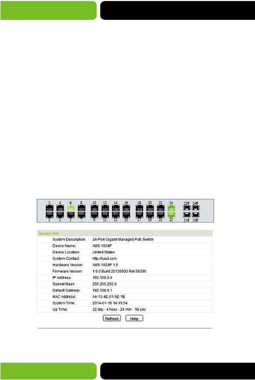
4.1.1 Status
This page allows you to view the Port connection status and the System Info.
The Port status diagram shows the status of the 24 10/100/1000Mbps RJ45 Ports and 4 SFP Ports of the Switch. Ports labeled as 1-24 are 10/100/1000Mbps Ports and Ports labeled as 21F-24F are SFP Ports.
Choose System>>System Settings>>Status to load the following page.
Figure 4-1 Status
16 |
a: 14203 Minuteman Drive, Suite 201, Draper, UT 84020-1685 | luxul.com | 801-822-5450 |
|
LUX-UG-XMS-1024P Vers: 081314 |
||
|

User Guide
Port Status
Indicates the Port is not connected to a device.
Indicates the Port is connected at the speed of 1000Mbps.
Indicates the Port is connected at the speed of 10Mbps or 100Mbps.
Indicates the SFP Port is not connected.
Indicates the SFP Port is connected at the speed of 1000Mbps.
Indicates the SFP Port is connected at the speed of 100Mbps.
When the cursor is used to highlight the Port, the detailed information of the Port will be displayed.
Figure 4-2 Port Information
Port Information
Port: |
Displays the selected Port number of the Switch. |
Type: |
Displays the configured type of the Port |
Speed: |
Displays the maximum transmission rate of the Port. |
Status: |
Displays the connection status of the Port. |
© 2014 Luxul. All Rights Reserved. |
17 |
|
Other trademarks and registered trademarks are the property of their respective owners |
||
|
XMS-1024P
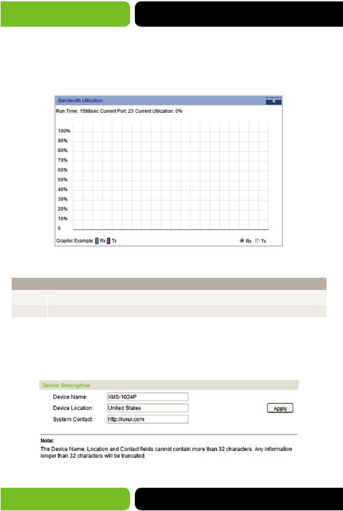
You may click a Port to display the bandwidth utilization chart for the Port. The actual rate divided by theoretical maximum rate is the bandwidth utilization. Figure 4-3 displays the bandwidth utilization monitored every four seconds. Monitoring the bandwidth utilization on a Port allows you to monitor the Network traffic and analyze the Network for any abnormalities.
Figure 4-3 Bandwidth Utilization
Bandwidth Utilization
Rx: |
Select Rx to display the bandwidth utilization of received packets on this Port. |
Tx: |
Select Tx to display the bandwidth utilization of sent packets on this Port. |
4.1.2 Device Description
On this page you can configure the description of the Switch, including Device Name, Device Location and System Contact.
Choose System>>System Settings>>Device Description to load the following page.
Figure 4-4 Device Description
18 |
a: 14203 Minuteman Drive, Suite 201, Draper, UT 84020-1685 | luxul.com | 801-822-5450 |
|
LUX-UG-XMS-1024P Vers: 081314 |
||
|
|
User Guide |
The following entries are displayed on this screen: |
|
|
|
Device Description |
|
Device Name: |
A name for the Switch is entered here. |
Device Location: |
Location information is entered here to help identify the location and |
|
purpose of the Switch. |
System Contact: |
Support or Admin contact information is entered here. |
NOTE: The Device Description settings will be restored to defaults if the Switch is restarted and you have not selected Save Config from the main menu and saved your running configuration to nonvolatile memory.
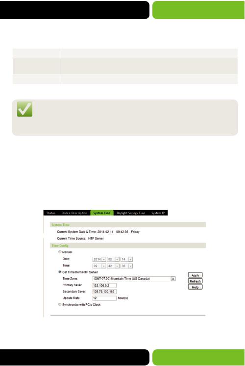
4.1.3 System Time
System Time displays the current time settings of the Switch. On this page you can configure the System Time settings. The settings here will be used for other time-based functions like Access Control List (ACL).
You can manually set the System Time, automatically aquire time from an NTP Server or synchronize with your PC’s clock.
Choose System>>System Settings>>System Time to load the following page.
Figure 4-5 System Time
The following entries are displayed on this screen:
© 2014 Luxul. All Rights Reserved. |
19 |
|
Other trademarks and registered trademarks are the property of their respective owners |
||
|

XMS-1024P
Time Info
Current System Date & Time: |
Displays the current date and time of the Switch. |
Current Time Source: |
Displays the current time source of the Switch. |
|
|
Time Config |
|
Manual: |
When this option is selected, you can set the date and |
|
time manually. |
Get Time from NTP Server: |
When this option is selected, you can configure the time |
|
zone and the IP Address for the desired NTP Server. The |
|
Switch will get time from NTP Server automatically if it |
|
has connected to a NTP Server. |
|
Time Zone: Select your local time zone. |
|
Primary/Secondary NTP Server: Enter an IP Address for the |
|
NTP Server(s). |
|
Update Rate: Specify in hours how often the Switch will |
|
check for an NTP time update. |
Synchronize with PC’S Clock: |
When this option is selected, the administrator PC’s clock is |
|
used to set the System Time. |
NOTE: The System Time settings will be restored to defaults if the Switch is restarted and you have not selected Save Config from the main menu and saved your running configuration to non-volatile memory.
NOTE: When “Get Time from NTP Server” is selected and no time Server is configured, the Switch will get it’s time from the time Server of the Default Gateway in the Network..
4.1.4 Daylight Savings Time
On this page you can configure the Daylight Savings Time settings of the Switch.
20 |
a: 14203 Minuteman Drive, Suite 201, Draper, UT 84020-1685 | luxul.com | 801-822-5450 |
|
LUX-UG-XMS-1024P Vers: 081314 |
||
|
User Guide
Choose the menu System>>System Settings>>Daylight Savings Time to load the following page.
Figure 4-6 Daylight Savings Time
The following entries are displayed on this screen:
DST Config
DST Status: |
Enable or Disable DST. |
Predefined Mode: Select a predefined DST configuration.
USA: First Sunday in April, 02:00 ~ Last Sunday in October, 02:00.
Australia: First Sunday in October, 02:00 ~ First Sunday in April, 03:00.
Europe: Last Sunday in March, 01:00 ~ Last Sunday in October, 01:00.
New Zealand: First Sunday in October, 02:00 ~ Last Sunday in March, 03:00.
Recurring Mode: Allows you to specify a DST configuration that will run in recurring pattern. Unless changed this mode will run each Start and End Time configured.
Offset: Specifies the change of time in minutes when a DST event occurs.
Start Time/End Time: Set the Starting and Ending week, day and month for DST in your geographical location.
© 2014 Luxul. All Rights Reserved. |
21 |
|
Other trademarks and registered trademarks are the property of their respective owners |
||
|
XMS-1024P
DST Config
Date Mode: |
Allows you to specify the DST configuration using a Date format instead of |
|
a week, day and month format. This configuration will not run in a recurring |
|
mode and must be set each year. |
|
Offset: Specifies the change of time in minutes when a DST event occurs. |
|
Start Time/End Time: Set the Starting and Ending dates for DST in your |
|
geographical location. |
NOTE: The DST settings will be restored to defaults if the Switch is restarted and you have not selected Save Config from the main menu and saved your running configuration to
non-volatile memory.
 NOTE: When DST is disabled the various modes cannot be configured.
NOTE: When DST is enabled the default daylight savings time will be set to USA in predefined mode.
4.1.5 System IP
Each device in an IP Network must have a unique IP Address. You log in to the Web Management page of the Switch using the Switches IP Address. The Switch supports three modes to set the IP Address: Static IP, DHCP and BOOTP. The IP Address set using the new mode selected will replace the current IP Address. On this page you can configure the system IP of the Switch.
Choose the menu System>>System Settings>>System IP to load the following page.
22 |
a: 14203 Minuteman Drive, Suite 201, Draper, UT 84020-1685 | luxul.com | 801-822-5450 |
|
LUX-UG-XMS-1024P Vers: 081314 |
||
|

User Guide
Figure 4-7 System IP
The following entries are displayed on this screen:
IP Config
MAC Address: |
Displays MAC Address or Hardware Address of the Switch. |
IP Address |
Allows you to select the desired mode for setting the IP Address of the Switch. |
Mode: |
Static IP: When this option is selected you set the IP Address, Subnet Mask |
|
|
|
and Default Gateway manually. |
|
DHCP: When this option is selected the Switch will obtain all IP Address |
|
settings from the DHCP Server in your Network. |
|
BOOTP: When this option is selected the Switch will obtain all IP Address |
|
settings from the BOOTP Server in your Network. |
Management |
Enter the ID of Management VLAN this will be the only VLAN through which |
VLAN: |
you can access the Management page of the Switch. By default VLAN1 is the |
|
Management VLAN and you can access the Switch via any Port on the Switch. |
|
However, if another VLAN is created and set to be the Management VLAN, you |
|
may have to reconnect the Management station to a Port that is a member of |
|
the Management VLAN. |
IP Address: |
The IP Address of the Switch. The default IP is 192.168.0.4, if you have selected |
|
the Static IP option you will be able to modify this address as desired. If DHCP |
|
or BOOTP is selected they will configure the IP Address. |
Subnet Mask: |
The Subnet Mask of the Switch. The default Mask is 255.255.255.0, if you have |
|
selected the Static IP option you will be able to modify this address as desired. |
|
If DHCP or BOOTP is selected they will configure the Subnet Mask. |
Default |
The Default Gateway of the Switch. The default Gateway is blank, if you have |
Gateway: |
selected the Static IP option you will be able to modify this address as desired. |
|
If DHCP or BOOTP is selected they will configure the Default Gateway. |
© 2014 Luxul. All Rights Reserved. |
23 |
|
Other trademarks and registered trademarks are the property of their respective owners |
||
|

XMS-1024P
NOTE: The System IP settings will be restored to defaults if the Switch is restarted and you have not selected Save Config from the main menu and saved your running configuration to non-volatile memory.
NOTE: Changing the IP Address to a different IP subnet (i.e. from 192.168.0.XXX to 192.168.1.XXX) will interrupt Network communication. Please keep the new IP Address in the same IP subnet as the rest of the local Network.
NOTE: The Switch only requires one IP Address. Any new IP Address configured will replace the original default IP Address.
NOTE: If the Switch gets an IP Address from the DHCP Server, you can find the IP configuration information of the Switch in the DHCP Server connected clients list. If DHCP option is selected but no DHCP Server exists, the Switch will keep trying to obtain the IP Address from DHCP Server until successful.
4.2 User Management
User Management allows you to configure the User Name and Password for log in to the Web Management page with the desired access level to protect the settings of the Switch from being changed by unauthorized users.
The User Management function can is implemented in the User Table and
User Config pages.
4.2.1 User Table
On this page you can view the information about the current configured users of the Switch.
Choose the menu System>>User Management>>User Table to load the following page.
Figure 4-8 User Table
24 |
a: 14203 Minuteman Drive, Suite 201, Draper, UT 84020-1685 | luxul.com | 801-822-5450 |
|
LUX-UG-XMS-1024P Vers: 081314 |
||
|

User Guide
4.2.2 User Config
On this page you can configure the Access Level of the user allowed to log in to the Web Management page. The Switch provides two access levels: Guest and Admin. The Guest user can only view the settings and status with no rights to actually configure the Switch; the Admin user can configure all functions of the Switch.
Choose the menu System>>User Management>>User Config to load the following page.
Figure 4-9 User Config
The following entries are displayed on this screen:
User Info |
|
User Name: |
Create a Name for a new User login. |
Access Level: |
Select the access Level to Apply to the User. |
|
Admin: Admin can edit, modify and view all the settings |
|
of the Switch. |
|
Guest: Guest only can view the settings and status of the Switch. |
User Status: |
Enable or Disable the User configuration. (Typically you would use this |
|
function on a previously configured user.) |
Password: |
Enter a Password for the Users login. |
© 2014 Luxul. All Rights Reserved. |
25 |
|
Other trademarks and registered trademarks are the property of their respective owners |
||
|
XMS-1024P
User Info
Confirm Password: |
Confirm the Password for the Users login. |
|
|
User Table |
|
Select: |
Select the desired entry to delete or edit the corresponding user |
|
information. If selecting multiple entries the only option available |
|
is Delete. |
User ID, Name, |
Displays the current User ID, User Name, Access Level and User Status. |
Access Level and |
|
status: |
|
Operation: |
Click the Edit link of the desired entry to edit the corresponding user |
|
information. After modifying the settings, please click the Modify |
|
button to save the modification. |
CAUTION: The User Config settings will be restored to defaults if the Switch is restarted and you have not selected Save Config from the main menu and saved your running configuration to non-volatile memory.
CAUTION: The default Admin user can be deleted please take care when selecting multiple users for deletion.
CAUTION: The User Name and Password can contain only 16 characters, if more than 16 characters are entered they will be truncated.
4.3 System Tools
The System Tools menu allows you to manage the system functions of the Switch including; Config Restore, Config Backup, Firmware Upgrade, System Reboot and Restore Factory Defaults.
26 |
a: 14203 Minuteman Drive, Suite 201, Draper, UT 84020-1685 | luxul.com | 801-822-5450 |
|
LUX-UG-XMS-1024P Vers: 081314 |
||
|
User Guide
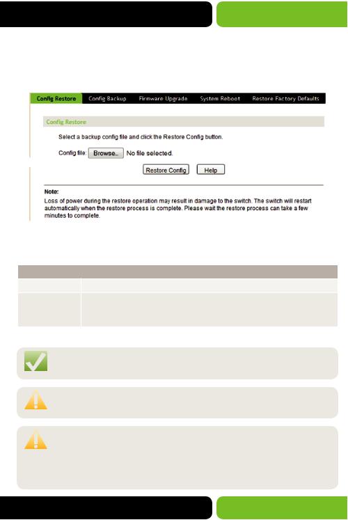
4.3.1 Config Restore
On this page you can upload a previous backup configuration file to restore your Switch to the desired configuration.
Choose the menu System>>System Tools>>Config Restore to load the following page.
Figure 4-10 Config Restore
The following entries are displayed on this screen:
Config Restore
Config File: |
Browse to the configuration backup file you would like to Restore. |
Restore Config: |
Click the Restore Config button to restore the backup configuration file. |
|
The Switch will automatically reboot as part of the Restore process and |
|
will load the Restored Config file after reboot. |
NOTE: It can take a few minutes to restore the configuration. Please wait for the operation to complete normally.
CAUTION: To avoid damage to the Switch please do not power down the Switch while a Restore operation is in process.
CAUTION: As part of the Restore process the current settings of the Switch will be lost. A corrupt or bad configuration file may cause the Switch to become unresponsive, if this occurs please power down the Switch and power back up to restore to the previous settings.
© 2014 Luxul. All Rights Reserved. |
27 |
|
Other trademarks and registered trademarks are the property of their respective owners |
||
|
XMS-1024P
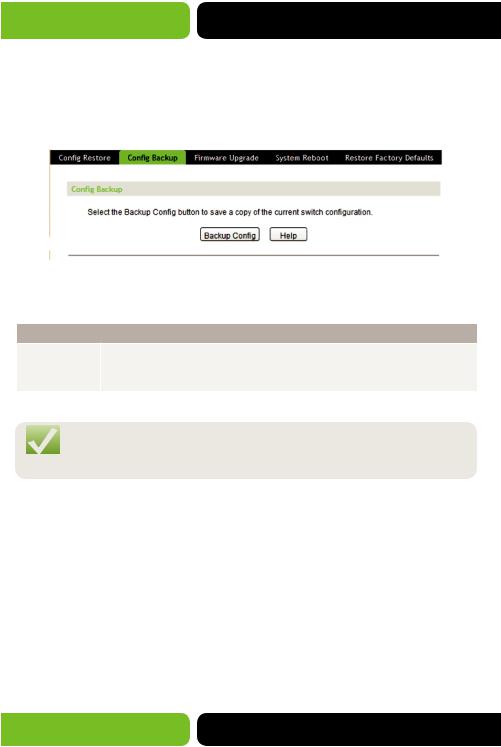
4.3.2 Config Backup
On this page you can download the current configuration of the Switch and save it as a file to your computer for your future configuration restore or to configure
future installations.
Choose the menu System>>System Tools>>Config Backup to load the following page.
Figure 4-11 Config Backup
The following entries are displayed on this screen:
Config Backup
Backup Config: Click the Backup Config button to save the current running configuration as a file on your computer. We recommend making a Config Backup before all Firmware Upgrades.
NOTE: It may take a few minutes to Backup the configuration. Please wait without any operation. Please wait for the operation to complete normally
4.3.3 Firmware Upgrade
The Switch Firmware can be upgraded via the Web Management page. Upgrades to the system Firmware can add more functionality, better performance, and/or resolve any known issues. Visit http://luxul.com to download the current firmware.
28 |
a: 14203 Minuteman Drive, Suite 201, Draper, UT 84020-1685 | luxul.com | 801-822-5450 |
|
LUX-UG-XMS-1024P Vers: 081314 |
||
|

User Guide
Choose the menu System>>System Tools>>Firmware Upgrade to load the following page.
Figure 4-12 Firmware Upgrade
The following entries are displayed on this screen:
Firmware Upgrade
Firmware File: |
Browse to the downloaded Firmware file and select it. Visit http:// |
|
luxul.com to download the current firmware. |
Current Firmware Version: |
Displays the current running version of Firmware on the Switch. |
Hardware Version: |
Displays the version of Hardware the Switch is running as new |
|
revisions are released they may not support all Firmware versions. |
|
Visit http://luxul.com for more information. |
Upgrade: |
Click the Upgrade button to Upgrade the current running Firmware |
|
of the Switch. We recommend making a Config Backup before all |
|
Firmware Upgrades. |
NOTE: We recommend making a Config Backup before all Firmware
Upgrades.
CAUTION: Do not interrupt the upgrade. To avoid damage to the Switch please do not power down the Switch while an Upgrade operation is in process.
© 2014 Luxul. All Rights Reserved. |
29 |
|
Other trademarks and registered trademarks are the property of their respective owners |
||
|
XMS-1024P
CAUTION: Please select the proper Firmware version matching your Hardware version. Visit http://luxul.com for more information.
NOTE: After the Upgrade process is complete the Switch will reboot automatically.
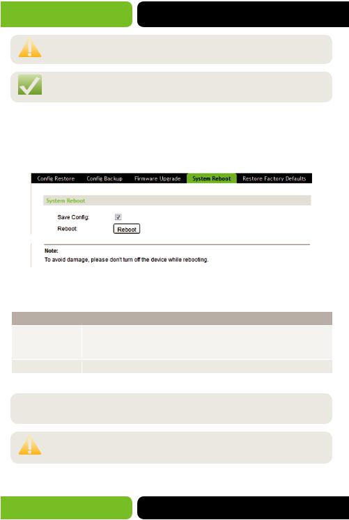
4.3.4 System Reboot
On this page you can Reboot the Switch. Please save the current running configuration before rebooting to avoid losing the configuration.
Choose the menu System>>System Tools>>System Reboot to load the following page.
Figure 4-13 System Reboot
The following entries are displayed on this screen:
System Reboot
Save Config: |
Leaving this checkbox checked will cause the Switch to save the |
|
Configuration to non-volatile RAM prior to Reboot. We recommend |
|
leaving this option checked. |
Reboot: |
Click the Reboot button to reboot the Switch. |
 NOTE: We recommend making a Config Backup before any Reboot.
CAUTION: To avoid damage to the Switch please do not power down the Switch while a Reboot operation is in process.
30 |
a: 14203 Minuteman Drive, Suite 201, Draper, UT 84020-1685 | luxul.com | 801-822-5450 |
|
LUX-UG-XMS-1024P Vers: 081314 |
||
|
 Loading...