

Page 1
http://www.thevintageknob.org/LUXMAN/L100/L100.html#
Luxman L -100
Although never a major player, Luxman is the oldest Japanese HiFi manufacturer, with a long history of
innovations in the field, as well as a unique status of a mass-market manufacturer, that never the less has a
line of truly high end components. The L-100 was Luxman's top of the line in 1976 to 1978, at which time it
retailed for a whopping $995. It was the pinnacle of what luxman's engineers could do with solid state at the
time (and pretty much pinnacle, period), equipped with every feature one could imagine.
FEATURES
Very conservatively rated at 110WPC into 8 ohms, it drives low impedances with ease. This is an amplifier
that is all about sound, but also has a ton of features. Two Phono inputs are provided with variable gain,
loading and Luxman's exclusive linear equalizer. A tuner (with variable sensitivity control, located in the
back), two AUX inputs, and two tape inputs (tape 2 with RCA and DIN interconnect) are also provided. The
power and pre sections are separable by removing jumpers on the rear panel. Signal routing alowes for
separate dub and monitor setup for tape decks.
Page 2
The filter and tone control section is feature rich, but completely defeatable never the less. The bass and
treble controls have three center frequencies each - 150, 300, 600Hz and 1.5k, 3k and 6kHz respectively.
The controls themselves are thick film on ceramic substrate switches rather than pots, with 1dB detents. A
bass boost is provided instead of the more traditional loudness control, defeatable in conjunction with the
tone controls. The filter section has a low/subsonic filter with 10Hz and 70Hz, and a high filter with 7kHz and
12kHz settings. This section is followed by a mono-stereo-reverse switch and a switch to drive only the left or
right channels (this is usable for simulcast FM).
Page 3
The volume control section is quite unique in having a dual volume and muting control - along with the main
volume control, which is again a thick film on ceramics switched attenuator, rather than the traditional
potentiometer, there is a separate attenuating pot that sets the 'baseline' volume inside a 20dB range. This
has a coaxial balance control. In addition, there is Luxman's unique touch-muting, which is defeatable via a
switch on the rear panel. Touching the central metal part on the volume control activates a 15dB attenuator
and lights the muting LED. Touching the outer metal ring of the volume control deactivates the 15dB
attenuation and switches off the LED. The control is 'touch-speed' sensitive - it only activates when you
quickly touch the metal ("bounce your finger off it"). The power amp section has switches for two speaker
pairs. Build quality is amongst the best offered at the time, and excellent (or better!) for today's standards.
Fair warning: it weighs a TON.
DETAILED INFO
This amp was the top of the line in 1976, and one of the most expensive integrated amplifiers of the day. The
price is no doubt due to the selection of components that could be considered to verge on esoteric for the
times. For instance, the audio signal only passes through foil capacitors, and the number of these has been
limited to as few as possible.
The amplifier features a truly high-end phono section, which, however only accepts MM cartridges (and with
fairly large output voltages at that), although I expect a high output MC will work fine assuming the gain of
the phono stage is set to it's highest. Instead of the variable capacitance control, luxman includes
continiously variable loading (from 10k to 100k), and their exclusive linear equalizer. This is a special type of
low phase shift filter that effectively tilts the whole responce towards the low or high end (depending on
setting). 5 settings are provided, flat plus approx. 2dB and 4dB tilt in either direction. The influence of the
control is quite subtle. The Phono section has no less than 4 power supplies, uses selected low noise
transistors and precision capacitors, and resides in a separate shielded box, as far as possible from the
power transformer.
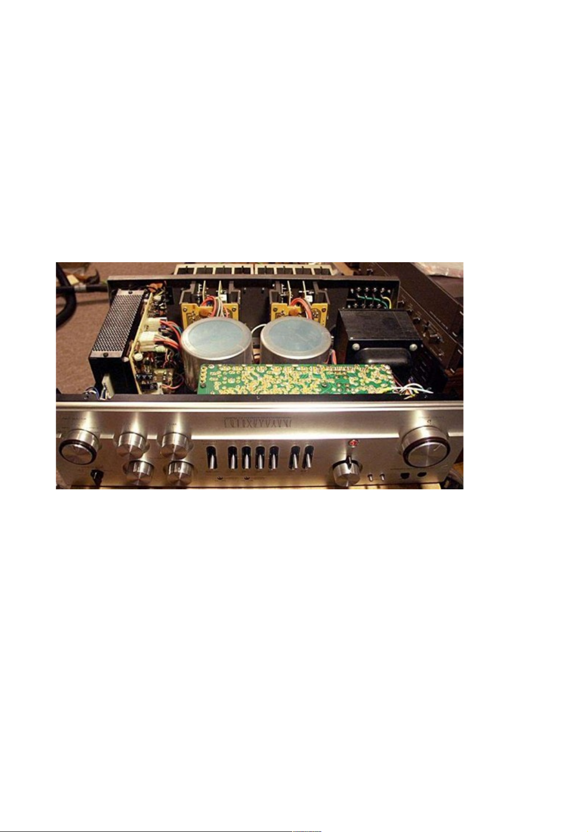
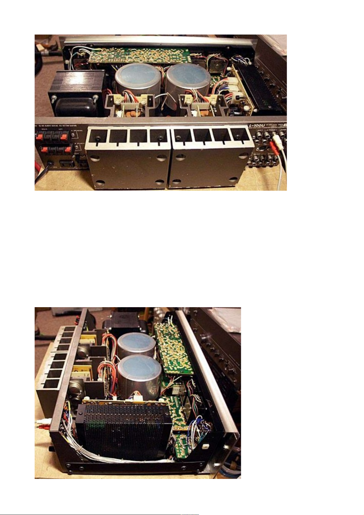
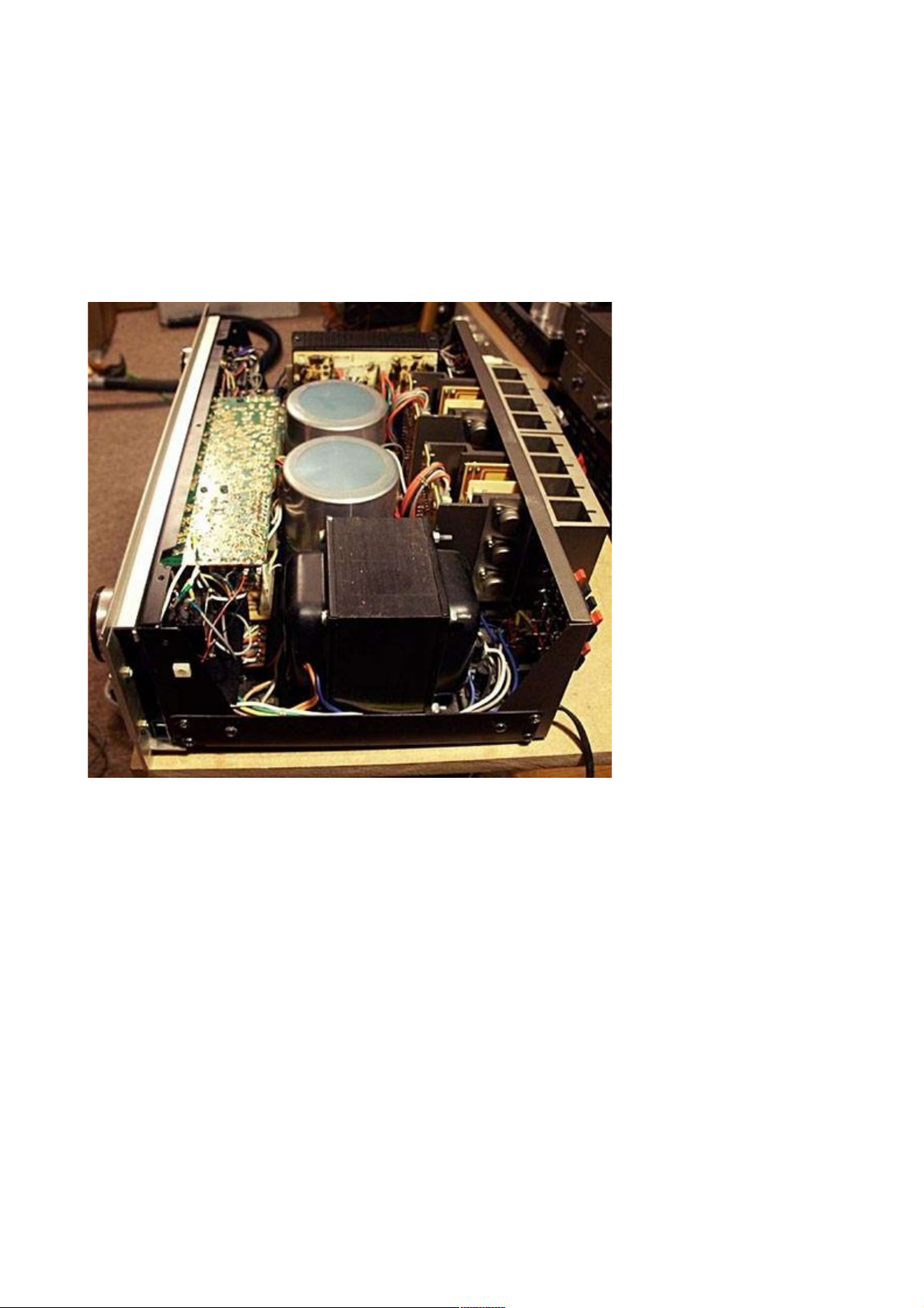
The power amps are two separate modules, powered by a huge transformer and two positively enormous
filter caps - these computer grade caps from Nippon Chemicon had to be ordered specially, the dimensions
are custom to the L-100. One eBay user described them as being as big as Saturn V booster rockets, and
the description fits! Needless to say, the power reserve of this amp is extraordinary.
The amplifier is a dual differential symetrical amplifier, as advanced as you get for the times - even today
some have not caught on yet. Two pairs of power transistors share the output current with an additional pair
of post-drivers - the output configuration uses a three stages. A comprehensive array of protection features
Page 4

in included (overcurrent, DC and temperature). The power output rating is quite conservative and the amp
quite easily pumps in excess of 130W into 8 ohms, and peaks at nearly 170 into 5 ohms. Clipping is very well
behaved, due to all stages except the power output itself having a separate stabilized power supply with a
huge headroom - it would remain in spec even when the mains supply were to drop to 80V.
Sonically, this amp is exactly what you would expect once you had a look inside. They did not save on this
one! The sound is best described as neutral verging on warm, but yet very precise - and that through my "my
impedance is all over the place but I'm 4 ohms nominal and deaf as a stump" monitors. It drove them just as
easy as it drove a pair of high impedance headphones. There were moments when I liked the sound of this
amp even more than that of my reference - a modded Sansui AU-20000, which is a bit more laid back. As
one would expect, this amp sounds similar to the L-11 I had on eBay a while ago, which is no surprise
considering the L-11 is ultimately a developement of the L-100, but the L-100 is sweeter and warmer, while
still very precise. Actually, now that I think of it, quite similar to the Kyocera A-710 I used to have.
The L-100's s reputation as one of the best amps of the 70s is well deserved.
+
Circuit Descriptions
The equalizer section employs 1-stage differential amplification whole-stage direct-coupled circuit with
cascode amplifier. The differential amplification circuit adopted at the initial stage helps stabilize DC
throughout the whole-stage direct-coupled circuit and a the same time improves linearity. Cascode amplifiers
are specially used at this differential amplifier and in the following stages to improve linearity at the treble
range as well as stability and S/N ratio.
The final stage consists of an inverted Darlington push-pull circuit of Class A operation, which keeps the
signals harmless from load connection given by tape-decks etc. Also at the various key points used are the
constant current supply circuits to obtain better linearity from the transistors located on the signal path and to
improve open loop-gain for perfect operation of the differential function.
At the intermediate and tone control amplifier sections, too, we used whole-stage direct-coupled circuits
with cascode amplifier so as to ensure optimum linearity at the treble range as well as stability and S/N ratio.
A constant current supply circuit at the output stage helps transistors play their role to the maximum
capability.
Luxman's exclusive NF type tone controls are provided together with turn-over (roll-off) frequency
selectors, which can be released if not necessary. Independent filter circuits of sharp slpoe (12dB/octave)
are provided for each cut-off frequency so that simple and perfect switch-over can be realized as a whole
circuit. Of course, signal bypass these filter if they are set at the "OFF" position.
This filter is of the NF type utilizing emitter-follower, but composed by 2 transistors wherein one is used for
emitter-follower while the other for the constant current purpose. Therefore, optimum linearity can be
obtained from the transistor of emitter-follower and high open loop-gain can be realized.
The main amplifier section employs 2-stage differential amplification whole-stage direct-coupled pure
complementary OCL circuit. Special power and driver transistors for high output power are used at the output
stage, and the final stage is composed by parallel push-pull configuration, which makes it possible to yield a
continuous output power of 110W per channel into 8Ohm loads.
The pre-driver stage uses a 2-stage differential amplifier circuit which is of higher stability and immune from
Page 5

environment conditions such as fluctuations of supply voltage and ambient temperature changes. The 2nd
stage of this circuit is driven by the constant current for the purpose of voltage amplification.
In between the pre-driver stage of Class A operation and the output stage of Class B operation, an emitterfollower stage is placed with 2 transistors, which electrically insulates both stages and safeguards the former
stage from possible influence of impedance fluctuation caused by speaker load. The negative feedback can
be applied equally to the whole frequency range from bass to treble, which makes it possible to drive this
amplifier at low distortion with good stability and small phase shift. To prevent intermodulation distortion
which is triggered by irregularity in Class A operation on the pre-amplifier section, the power transformer
has completely separate windings for Class A and Class B operation, and perfect constant current circuits
are provided at the power supply section to the Class A operation portion.
And also 2 computer-grade giant capacitors of 15,000uµF are used for the power supply filtering to the
output stage. Other complex protection circuite are added to safeguard not only the amplifier but your
loudspeakers from accidental damages. A muting circuit which eliminates unpleasant thumps at the time of
switching is also present.
The L-100 offers the ultimate in precision and elegance.
OPERATIONAL FEATURES
Linear Equalizer
Although recordings are equalized in accordance with RIAA standards, it is quite common to encounter
variations in overall tonal balance from one recording to the next. In addition, differences in listening
environment and room acoustics often require subtle degrees of tonal compensation that conventional tone
controls cannot correct because of their wide range and overlapping crossover characteristics.
With the Linear Equalizer set in the mid position, flat frequency response is achieved. Switched to either of
the two "up-tilt" positions, the entire response curve is rotated about a 1kHz fixed axis so as to linearily
increase treble response while simultaneously decreasing bass response. Conversely, selection of one of
the "down-tilit" positions rotates the curve in a clockwise direction, providing a gradual decreas of the treble
response and simultaneous increase of bass response. Degree of slope for either positive or negative
settings has been carefully preset, and the overall response curve maintains complete linearity from 50Hz to
above 10kHz, unlike the curvature in response normally associated with ordinary tone controls. The
combined use of Linear Equalizer and conventional tone controls provides a degree of tonal flexibility which
cannot be achieved with any other tone control arrangement presently available. Because of the inherently
linear nature of this nex circuit, it introduces no increase in harmonic distortion at any of its settings.
Touch Mute Switch
To operate the new electronic muting circuitry, a slight touch on the center of the volume knob ensures
operation: gain is reduced by 20dB and the volume is reduced by 1/10. Cancellation is possible by touching
the outer metal part of the knob and sound level returns to normal operation.
Page 6

Volume Control
The variable resistor of this control has logarithmic curve. In the attenuation characteristics of A type, the
turning angle is proportionate to the attenuation degree (dB), the dB value and the volume audible to human
ears are in the proportionate relation. In other words, the rotation of the control is in proportion of the sound
volume felt by human ears. The increasing degree of volume is felt quite natural as the control is turned in
the clockwise direction. A precision detent-volume of high-grade attenuator type ensures a precise
adjustment on both right and left channels.
Input Impedance Adjuster
The PHONO-1 input terminals are coupled with the Impedance Adjuster. Except for a special low impedance
type cartridge almost all currently marketed cartridges of MM-type specify recommended load impedance of
about 50kOhm. It is known that the variation of the load impedance value affects the frequency response to a
grea extent. A low impedance load cuts treble output, while a high impedance load causes a peak in the
treble range. The degree of such effects is not the same with different cartridges, but generally a cartridge
having a higher output impedance tends to be more delicately influenced.
The adjustment of Input Sensitivity is done by a potentiometer, and free adjustment is feasible between
30kOhm and 100kOhm. Each position of the 30kOhm, 50kOhm and 100kOhm has click stopper for easy
identification.
Input Sensitivity Adjuster
Of all the various types of cartridges, the most predominant are the MM (Moving Magnet), MI (Moving Iron)
and MC (Moving Coil). The PHONO terminals are designed to match these types of cartridges but a
cartridge of low output level (0,01 to 0,1mV) cannot be directly connected. Input sensitivity adjustments is
feasible both at PHONO 1 and PHONO 2 terminals. Free adjustment of +/- 5dB is possible in case the input
sensitivity of 3mV is regarded as 0dB. That is, the most suitable sensitivity to the cartridge can be obtained
between some 1,7mV and 5mV in view of the fact that the sensitivity at +/-5dB is some 1,7mV and at -5dB is
5mV.
2x 110 Watt an 8 Ohm
Page 7

 Loading...