


USB D/A CONVERTER
DA-250
Owner`s Manual


USB D/A CONVERTER DA-250
Contents
Precautions ············································································································· 1
Features of This Unit ································································································ 3
Names and Functions ······························································································ 5
Connections ·········································································································· 15
Operations ············································································································· 18
Block Diagram ······································································································· 20
Specifications ········································································································ 21
Before Asking for Repair Services ·········································································· 23

Precautions
Installation place
• Choose a stable place near the devices that are to be
used in combination with this unit.
• Do not install this unit near a television or color monitor.
Keep this unit away from such devices as cassette decks
that are susceptible to magnetic.
Avoid the following locations for
installation.
• Locations exposed to direct sunlight
• Places subject to humidity and with less ventilation
• Places where it is extremely hot or cold
• Places subject to strong vibration
• Places subject to dust
• Places subject to oil, steam, and heat (such as kitchens)
To avoid heat emission
Do not place this unit on such device as an amplifier that
may emit heat. If the unit is installed on a rack, install the unit
as distantly as possible from where the amplifier is installed
so as to avoid heat emission from the amplifier and other
audio devices.
Turn off this unit when it is not used.
Depending on the condition of radio waves emitted during
television broadcasting, interference fringes may appear on
the television monitor, but that is not a malfunction. In such
a case, turn off the unit. There may also be a case where
noises are heard on the radio due to radio wave interfer-
ence.
Notice when handling optical digital cables
• Do not fold the cables. For storage, wind each cable to
make a coil whose diameter is approx.15 cm or larger.
• For connection, insert the cable connectors firmly into the
terminals of this unit and the other device.
• Use the cables whose each length is 3 m or less.
• When the cable connectors get dusty, wipe the dust
away with a dry soft cloth before inserting into the termi-
nals.
Batteries
Caution:
Batteries used for remote controller shall not be exposed to
excessive heat such as sunshine, fire or the like.
Safety caution: Lithium battery
Warning Caution
• Put the lithium battery out of baby's reach.
• In case that the battery is swallowed, consult a doctor im-
mediately.
• Do not disassemble, throw in a fire, recharge, heat, solder,
or short-circuit the battery.
• Do not use or leave the battery in a hot place such as un-
der strong direct sunlight, in a car under the blazing sun,
and in front of a heater. Failure to observe this may cause
battery liquid leakage, heat generation, rupture, or ignition.
This may also degrade the performance or shorten the life
of the battery.
1
• Danger of explosion if battery is incorrectly replaced.
• Replace only with the same or equivalent type.
• If the battery is not used for a long time (1 month or more),
the battery shall be removed from the case to prevent bat-
tery liquid leakage. If the liquid leaks from the battery, wipe
the liquid off inside the case completely and load a new
lithium battery.
• To discard a used lithium battery, follow the instructions of
each local authority.

USB D/A CONVERTER DA-250
Cleaning
• Usually, wipe the unit with a dry soft cloth. When the dirt
is hard to remove, dip soft cloth in detergent diluted 5 or
6 times with water, wring it well, and remove contami-
nants. Then, remove the moisture with dry cloth.
• Do not use a solvent like alcohol, benzine, thinner, or
pesticide because such a substance can damage the ex-
terior. In addition, do not let this unit contact a rubber or
plastic form for a long time. That may damage the cabi-
net surface of the unit.
• When using a chemical cloth for cleaning, read the cau-
tion provided with the chemical cloth product.
• Before cleaning, unplug the power cord from the AC out-
let.
Precautions in connecting with other
components
When connecting this unit to input/output devices other
than a PC/Mac such as a CD player, an SACD player, a
DVD player, a tuner, and a power amplifier, be sure to turn
off the power of this unit and all other connected devices.
Failure to observe this may generate a strong noise resulting
in speaker damage or cause a malfunction.
The pin-plug to be inserted in each input terminal of this
unit shall be pushed in firmly. If the grounding terminal is
inadequately connected, noises including hum may be gen-
erated, resulting in an adverse S/N ratio.
Protection circuit
This unit is equipped with a protection circuit that is activat-
ed upon the detection of overcurrent to protect the head-
phones. When the protection circuit is activated, the output
to the headphones is shut off and the operation indicator
blinks to show that this unit is in the muting state. When
the cause to activate the protection circuit is eliminated, the
blue operation indicator light comes back on and the op-
erating state resumes. If the protection circuit is frequently
activated, please consult your dealer.
Insertion and extraction of headphone plug
When the headphone (unbalanced) plug is inserted or ex-
tracted, a short circuit occurs between the L ch output and
R ch output because of the structure of the headphone jack
(unbalanced).
If the volume of this unit is turned up at this moment, an
overcurrent flows to the headphone amplifier output and the
overcurrent detection circuit becomes activated, which sets
this unit to the muting state and may also cause a malfunc-
tion. Therefore, the insertion and extraction of the head-
phone plug shall be performed when the volume is turned
down to the minimum or when there is no signal after shut-
ting off input signals.
Repair and adjustment
When repairs or adjustments are needed, please ask the
dealer where you bought the unit.
Caution in using headphones
If the headphones are used for a long time at a high sound
volume level, your hearing may be damaged.
2

Features of This Unit
Compact chassis design
This unit is a D/A converter that has a compact body as
small as B4-paper size.
PCM1795 manufactured by Burr-Brown
For the DAC chip, this unit uses PCM1795 manufactured
by Burr-Brown that is used for the LUXMAN SACD player,
D-05u.
USB input supports 192 kHz / 32 bit
B-type USB input terminal is installed and makes it possible
to input USB digital audio signal from a PC/Mac.
The sampling frequency of up to 192 kHz and 32-bit quan-
tization are supported.
USB input supports DSD
DSD format data can be entered from PC/Mac, or the like.
Sampling frequencies of 2.8224 MHz/5.6448 MHz is sup-
ported.
Asynchronous communication supported
The USB input with low jitter has been achieved with USB
dedicated IC by asynchronous communication and PLL.
DD converter function
All the digital inputs including USB can be digitally output in
the S/PDIF format.
AD converter function
Analog line inputs can be converted into digital signals in
the S/PDIF format and output with coaxial or optical termi-
nal. Signals can be output as analog signals by the internal
DAC. (sampling frequency 96 kHz/24-bit)
3

USB D/A CONVERTER DA-250
LECUA (LUXMAN Electric Controlled
Ultimate Attenuator)
An electrically controlled attenuator LECUA, in which at-
tenuation is obtained by combining resistances, is used in
the headphone amplifier unit and analog output unit inde-
pendently to achieve fresh sound.
Built-in headphone amplifier
A high-grade headphone amplifier circuit with discrete cir-
cuit configuration is equipped. The output level can be se-
lected from 2 stages in accordance with the sensitivity of
headphones.
Built-in pre-amplifier circuit
A pre-amplifier circuit equipped with LECUA is embedded
in the analog output.
It is possible to connect the unbalanced or balanced out-
puts to the power amplifier and other directly, so that sound
volume can be controlled.
7-segment LED
The sampling frequency of the digital input and the select-
ed input can be displayed on the monitor with 7-segment
LEDs with a high level of visibility. The attenuation amount
is displayed during sound volume adjustment. The dimmer
function allows the brightness of the LEDs to be selected
from 4 levels.
Original technologies
Our traditional round pattern board, OFC internal wiring, and
original custom-made parts are fully and luxuriously used.
Remote control (RD-24)
Operations can be performed with a compact card-type
remote control.
*1 Mac and Mac OS are trademarks of Apple Inc., registered
in the U.S. and other countries.
*2 Windows is a registered trademark of Microsoft Corpora-
tion in the United States and/or other countries.
*3 DSD is a trademark.
*4 The described company names and product names are
trademarks or registered trademarks of each company.
4

Names and Functions
1 3 52
86 107 9 1211
4
Front panel
1. Operation switch (OPERATION)
This switch turns on and off the power.
When wiring or connection is performed, be sure to turn off
this switch.
2. Operation indicator (OPERATION)
Blinks in the time of muting mode when the operation
switch is turned on and lights up when the operation state
is activated afterward.
3. Input selector (INPUT)
Selects an input device connected to each input terminal.
Input transition goes as follows by clockwise rotation:
USB → COAX → OPT 1 → OPT 2 → LINE → USB ...
Input transition goes as follows by counterclockwise rotation:
USB → LINE → OPT 2 → OPT 1 → COAX → USB ...
Input: Digital output from a PC/Mac, a CD player,
an SACD player, a DVD player, and other such
devices (USB/COAX/OPT 1/OPT 2)
Analog line output from a CD player, an SACD
player, a tuner, a DVD player, a TV, and other such
devices (LINE)
4. Input selector display LED
Displays the input terminal selected with the input selector.
The input terminals are shown as follows:
USB input: USb
COAX input: COA
OPT 1 input: OP1
OPT 2 input: OP2
LINE input: LIn
5. Sampling frequency/volume level
display LED
(SAMPLING RATE/VOLUME)
Displays the sampling frequency of the digital signal con-
nected to the input terminal (USB/COAX/OPT 1/OPT 2)
selected with the input selector. When a digital input is
selected from USB/COAX/OPT 1/OPT 2 with the input se-
lector and the digital input signal from the digital device is
synchronized with this unit, the sampling frequency of the
digital signal is displayed on this LED.
When no digital signal is input or no synchronization is es-
tablished even with a digital signal input, the digital signal
unlock indicator lights up, and the sampling frequency is not
displayed on the LED.
When playback from a PC/Mac is stopped, the sampling
frequency disappears and the unlock indicator stays off.
This phenomenon indicates that communication with the
PC/Mac stays active.
5

USB D/A CONVERTER DA-250
This LED indicates the current volume level in steps of 1 dB
during sound volume adjustment.
• "- - -" shows the mute state. No sound is generated.
• The minimum volume level is shown as "–87 dB", and the
maximum volume level is shown as "0 dB".
The following sampling frequencies can be displayed.
Input from the USB
terminal
Input from OPT/
COAX terminals
First 3 digits are displayed on the LED.
PCM : 32 kHz, 44.1 kHz, 48 kHz,
88.2kHz, 96 kHz, 176.4 kHz,
192 kHz
DSD : 2.8224 MHz, 5.6448 MHz
: 32 kHz, 44.1 kHz, 48 kHz,
88.2 kHz, 96 kHz, 176.4 kHz,
192 kHz
6. Phase invert indicator (PHASE INVERT)
Lights up when the analog output phase is inverted by
pressing the phase invert changeover switch (PHASE) on
the remote control.
The following shows balanced output phases:
When the [Light is off]
1. GROUND
2. COLD (–)
3. HOT (+)
When the [Light is on]
1. GROUND
2. HOT (+)
3. COLD (–)
Both the unbalanced output and headphone output are in-
verted.
7. Headphone terminal sensitivity
indicator (SENSITIVITY HIGH)
Lights up when the headphone terminal sensitivity selection
switch (SENS.) is set to HIGH.
When the [Light is off]
NORMAL: Sensitivity setting 0 dB
When the [Light is on]
HIGH: Sensitivity setting +9 dB
8. Remote control infrared receiver (R)
Receives signals from the accessory remote control.
9. Digital signal unlock indicator
(UNLOCK)
Lights up when a digital input is selected from USB/COAX/
OPT 1/OPT 2 with the input selector and the digital input
signal from the digital device is not synchronized with this
unit.
10. Analog output level fix indicator (FIX)
Lights up when the analog output level fix/variable selection
switch (FIX/VARIABLE) on the rear panel is set to FIX.
At this moment, the volume control cannot adjust the ana-
log output level. (The sound volume of the headphones can
be adjusted regardless of the status of the selection switch.)
11. Volume control (VOLUME)
Adjusts the sound volume of the headphones, and the
sound volume of the device connected to the analog un-
balanced output terminals (RCA) or balanced output termi-
nals (XLR) when the analog output level fix/variable selection
switch (FIX/VARIABLE) on the rear panel is set to VARI-
ABLE. Sound is not generated when this control is rotated
counterclockwise to the end, and then, the sound volume
gradually becomes higher when the control is slowly rotated
clockwise.
When the analog output level fix/variable selection switch
(FIX/VARIABLE) on the rear panel is set to FIX, the analog
output level is not changed even if the volume control is
rotated.
12. Headphone jack (PHONES)
When listening to the playback sound of this unit with ste-
reo headphones, insert the headphone standard plug in this
output jack.
If the plug of your headphones is mini, use a mini-to-stan-
dard adapter that comes with the headphones or available
on the market.
The phase can be changed with the analog output phase
selection switch (PHASE) on the remote control.
DA-250 FIX/VARIABLE setting table
Output
Setting
FIX Variable Fixed
VARIABLE Variable Variable
Headphone
output
Analog output Digital output
RCA/XLR OPT/COAX
○ (Fixed)
○ (Fixed)
6

Names and Functions
17 1815 16 19 20 21
14 2213
Rear panel
13. Analog balance output terminals (XLR)
XLR connector terminal to output balanced playback sig-
nals from this unit.
The phase can be changed with the analog output phase
selection switch (PHASE) on the remote control.
The following are the phases of the output terminals of this
unit:
Normal 1. GROUND
2. COLD (–)
3. HOT (+)
Invert 1. GROUND
2. HOT (+)
3. COLD (–)
When the analog output level fix/variable selection switch
(FIX/VARIABLE) is set to VARIABLE, the output level varies
depending on the state of the volume control (VOLUME) on
the front panel.
14. Analog unbalance output terminals
(RCA)
RCA terminal to output unbalanced playback signals from
this unit.
The phase can be changed with the analog output phase
selection switch (PHASE) on the remote control.
When the analog output level fix/variable selection switch
(FIX/VARIABLE) is set to VARIABLE, the output level varies
depending on the state of the volume control (VOLUME) on
the front panel.
15. Analog output level fix/variable
selection switch (FIX/VARIABLE)
Sets the level of the playback signals from the analog output
terminal to FIX or VARIABLE.
When this switch is set to FIX, the analog output level fix
indicator (FIX) lights up to indicate that the output level from
the analog output terminal (RCA, XLR) is fixed and cannot
be adjusted with the volume control.
When the switch is set to VARIABLE, the output level of the
analog output terminal (RCA, XLR) can be adjusted with the
the volume control on the front panel or the remote control.
The sound volume of the headphones can be adjusted re-
gardless of the status of the selection switch.
When the selection switch is switched, the output level
may change greatly.
Be careful of the sudden change of the sound volume.
7

USB D/A CONVERTER DA-250
16. USB digital input terminal (USB)
USB (B-type) input terminal used for the digital input signal
from such device as a PC/Mac to be connected with a USB
cable.
The terminal supports the following signals.
• PCM signal
Sampling frequency: 32 kHz, 44.1 kHz, 48 kHz,
88.2 kHz, 96 kHz,
176.4kHz, 192 kHz
Number of quantization bits: 16 bit, 24 bit, 32 bit
• DSD signal
Sampling frequency: 2.8224 MHz, 5.6448 MHz
Number of quantization bits: 1 bit
When the OS is Windows, the dedicated driver software
needs to be downloaded from LUXMAN website and in-
stalled.
Refer to "Driver Installation Manual" on the LUXMAN web-
site for detailed information.
With Mac, this unit is automatically recognized.
Caution:
Connection between a PC and this unit with use of a USB
cable shall not be performed before the installation of this
driver software is completed. Failure to observe this may
cause a malfunction.
17. Analog input terminals (ANALOG IN)
RCA input terminals used for the line level input signals from
a CD player, an SACD player, a tuner, a DVD player, a TV,
and other such devices.
18. Digital input terminal (COAX)
RCA input terminal used for the digital input signals from
such device as a CD player equipped with digital output
terminals using a coaxial digital cable.
The terminal supports the following data.
Sampling frequency: 32 kHz, 44.1 kHz, 48kHz,
88.2 kHz, 96 kHz,
176.4kHz, 192 kHz
Number of quantization bits: 16 bit, 20 bit, 24 bit
19. Digital input terminal (OPT 1/OPT 2)
TOS-LINK input terminal used for the digital input signals
from such device as a CD player equipped with digital out-
put terminals using an optical digital cable.
The terminal supports the following data.
Sampling frequency: 32 kHz, 44.1 kHz, 48kHz,
88.2 kHz, 96 kHz,
176.4kHz, 192 kHz
Number of quantization bits: 16 bit, 20 bit, 24 bit
20. Digital output terminal (COAX)
RCA output terminal used to output digital signals input to
the digital input terminal (USB/COAX/OPT 1/OPT 2) and
digital signals converted from analog input signals.
The input signals selected with the input selector are out-
put. The sampling frequency and the number of quantiza-
tion bits of the digital output signal are the same as those
of the input signals. The frequency for an analog input is
96kHz.
When a DSD file or the PCM data of 32 kHz sampling fre-
quency is played back, a digital audio output cannot be
provided.
21. Digital output terminal (OPT)
TOS-LINK output terminal used to output digital signals in-
put to the digital input terminal (USB/COAX/OPT 1/OPT 2)
and digital signals converted from analog input signals.
The input signals selected with the input selector are out-
put. When a DSD file or the PCM data of 32 kHz sampling
frequency is played back, a digital audio output cannot be
provided.
This terminal is a shutter-type. Direct the cable connector
correctly when inserting the cable into the terminal. If the
cable connector is inserted forcedly to the wrong direction,
the terminal may be deformed, and the shutter may not be
able to close even after cable disconnection.
22. AC inlet (AC IN)
Connects the accessory power cable to supply the power
from the AC outlet on the wall.
8

Names and Functions
Remote control
5
6
1
2
3
4
7
8
1. Digital filter selection switch (PCM)
This switch changes the interpolation function of the 32-bit
digital filter while the PCM data is played back.
Select a filter depending on your taste. The sound quality
can be changed.
There are 2 types of filters, P-1 and P-2
Pressing this switch displays the current setting data (P-1,
P-2) on the display window.
When pressing this switch again while the setting data is
displayed, the next setting data will be displayed.
Pressing the enter switch (ENTER) while the setting data is
displayed determines the setting data.
If the enter switch is not pressed, the digital filter is not
changed.
The impulse response of the interpolation function shows
the waveform shown on this page.
This setting is stored on the flash memory even when the
power is turned off.
P-1 (normal FIR filter)
P-2 (low latency IIR filter)
9

USB D/A CONVERTER DA-250
0
Frequency
Gain − dB
0
Frequency
Gain − dB
2. Analog FIR filter selection switch (DSD)
This switch changes the analog FIR filter while the DSD file
is played back.
Select a filter depending on your taste. The sound quality
can be changed.
There are 2 types of filters, d-1 and d-2.
Pressing this switch displays the current setting data (d-1,
d-2) on the display window.
When pressing this switch again while the setting data is
displayed, the next setting data will be displayed.
Pressing the enter switch (ENTER) while the setting data is
displayed determines the setting data.
If the enter switch is not pressed, the filter is not changed.
The analog FIR filter features the following:
d-1 (normal analog FIR filter)
−3
−6
0 100 200 kHz
d-2 (high attenuation analog FIR filter)
−3
−6
0 100 200 kHz
Depending on the filter selection, there is a difference in sound
volume. When d-1 is selected, the output voltage is 1.2 Vrms.
When d-2 is selected, the output voltage is 1.7 Vrms.
10

Names and Functions
1
5
6
2
3
4
3. Analog output phase selection switch
(PHASE)
The phases of the analog output on the rear panel and the
headphone output are inverted.
The balanced output, unbalanced output, and headphone
output are inverted together.
Pressing this switch displays the current setting data (3-P,
2-P) on the display LED.
When pressing this switch again while the setting data is
displayed, the next setting data will be displayed.
Pressing the enter switch (ENTER) while the setting data is
displayed determines the setting data.
If the enter switch is not pressed, the setting data will not
be changed.
This setting is stored on the flash memory even when the
power is turned off.
7
8
[Normal Position]
Indicates that the 3-Pin of the balanced output is positive.
1. GROUND
2. COLD (–)
3. HOT (+)
[Invert Position]
Indicates that the 2-Pin of the balanced output is positive.
1. GROUND
2. HOT (+)
3. COLD (–)
PH
Set as PH, 3-P
3-P
PH
Set as PH, 2-P
2-P
11

USB D/A CONVERTER DA-250
4. Enter switch (ENTER)
This switch is pressed to execute the set or selected items.
5. Volume control switches (VOLUME)
Adjust the output level of this unit.
Pressing these switches change the output level.
• Pressing ▲ increase the sound volume.
• Pressing ▼ decrease the sound volume.
When FIX is selected, the volume control cannot work be-
cause the analog output level is set to the maximum.
6. Dimmer switch (DIMMER)
Adjusts the brightness of the input selector and sampling
frequency display LEDs. The brightness can be adjusted in
4 stages from normal to light off.
Every time the switch is pressed, the transition goes as fol-
lows: normal (HI) → dim (L01) → very dim (L02) →light off
(OFF) → normal (HI) ....
The setting is determined by pressing the ENTER key (EN-
TER) while the selected brightness is flashing on the display
LED, or after approximately 5 seconds with nothing done.
8. Headphone terminal sensitivity selector
(SENS.)
Selects between HIGH and NORMAL in accordance to the
efficiency of the headphones to be used.
If the efficiency of the headphones is low and the sound
volume is not sufficient even if the volume control is rotated
to turn up the sound volume, select HIGH.
If the efficiency of the headphones is high and controlling
the sound volume is difficult, select NORMAL.
The sensitivity of this unit is set to the following:
HIGH: +9 dB
NORMAL: 0 dB
When this selector is set to HIGH, the headphone termi-
nal sensitivity indicator, SENSITIVITY HIGH, of the main unit
lights up.
7. Input selector (USB, COAX, OPT 1,
OPT 2, LINE)
Selects an input terminal on the rear panel.
During input selecting operation, muting circuit is in opera-
tion and the unit will be on mute.
The display LEDs of the main unit are shown as follows:
USB: USb
COAX: COA
OPT 1: OP1
OPT 2: OP2
LINE: LIn
12
Names and Functions
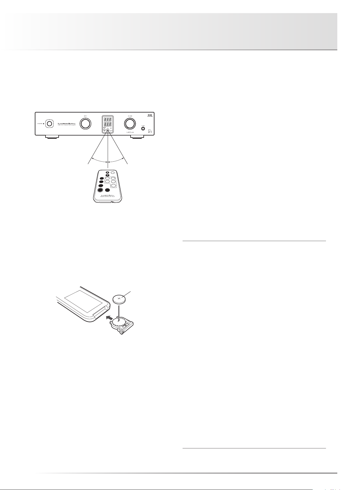
Effective distance: approx. 5 meters
Remote control
The remote control shall be aimed at the remote control
infrared receiver (R) of this unit within the specified angle
range shown in the illustration below when used.
30°30°
Battery
1. Put your finger on the battery cover claw on the rear of the
remote control, and slide the cover downward to open it.
2. Put a coin-type lithium battery (CR2025) in the battery case
as shown in the illustration.
⊕ side
3. Close the battery cover.
* When the batteries start to lose power, the effective dis-
tance becomes shorter or the unit does not function even
though the switch is pressed. In such a case, replace the
existing battery with new one.
* If the remote control is not used for a long time (1 month or
more), the battery shall be removed from the case.
Warning
About lithium battery
• Put the lithium battery out of baby's reach.
• In case that the battery is swallowed, consult a doctor
immediately.
• Do not disassemble, throw in a fire, recharge, heat,
solder, or short-circuit the battery.
• Do not use or leave the battery in a hot place such as
under strong direct sunlight, in a car under the blazing
sun, and in front of a heater. Failure to observe this
may cause battery liquid leakage, heat generation,
rupture, or ignition. This may also degrade the perfor-
mance or shorten the life of the battery.
Caution
• Danger of explosion if battery is incorrectly re-
placed.
• Replace only with the same or equivalent type.
• If the battery is not used for a long time (1 month or
more), the battery shall be removed from the case to
prevent battery liquid leakage. If the liquid leaks from
the battery, wipe the liquid off inside the case com-
pletely and load a new lithium battery.
• To discard a used lithium battery, follow the instruc-
tions of each local authority.
13

USB D/A CONVERTER DA-250
14

Connections
POWER AMP
INTEGRATED AMP D/A CONVERTER
TUNER
L
L R
R
(F) (E) (G)
RL
RL
(To the headphone jack on the
front panel of this unit)
HEADPHONE
CD PLAYER
(with digital input terminals)
(G)
15
PC/Mac
(A)
(D)
(B)
L
R
CD/SACD PLAYER DVD PLAYER
(C)

Before Connecting
Before connecting other devices, connect the jack side of
the accessory power cable to the AC inlet of this unit.
When connecting, turn off the power supply of this unit and
the power supplies of auxiliary devices to prevent unex-
pected accidents that may be caused by noise.
How to connect power supply
Use the accessory power cable to insert the AC plug in an
outlet on the wall in the listening room.
USB D/A CONVERTER DA-250
16
Connections
How to connect input devices
1. Digital connection from a PC/Mac
(Refer to "A" in the connection diagram)
Connect between the USB (A-type) terminal of the PC/Mac
and the USB (B-type) terminal of this unit with a USB cable.
When the OS is Windows, the dedicated driver software
needs to be downloaded from LUXMAN website and in-
stalled.
Refer to "Driver Installation Manual" on the LUXMAN web-
site for detailed information.
With Mac, this unit is automatically recognized.
Caution:
Connection between a PC and this unit with use of a USB
cable shall not be performed before the installation of this
driver software is completed. Failure to observe this may
cause a malfunction.
2. Digital connection from such device as a CD
player
(Refer to "B" and "C" in the connection
diagram)
Connect between the (coaxial or optical) digital output ter-
minal of a CD player, an SACD player, a DVD player, and
other such devices and the digital input terminal (COAX/
OPT 1/OPT2) of this unit with a coaxial digital cable or an
optical digital cable.
This terminal is a shutter-type. Direct the cable connector
correctly when inserting the cable into the terminal. If the
cable connector is inserted forcedly to the wrong direction,
the terminal may be deformed, and the shutter may not be
able to close even after cable disconnection.
Upper side
The optical terminals are directed as illustrated.
Lower side
How to connect output devices
1. Unbalanced connection with such device as
an integrated amplifier
(Refer to "E" in the connection diagram.)
Connect between the analog unbalanced output terminals
(RCA) of this unit and the unbalanced input terminals of
such device as an integrated amplifier with 2 RCA pin-plug
cables.
At this connection, the sound volume of the output signal
change in accordance with the state of the line output level
fix/variable selection switch (FIX/VARIABLE).
FIX/VARIABLE
selection switch
FIX lit up Always fixed
VARIABLE off
indicator
Sound volume
FIX
of the output
signal
Interlocked
with the volume
control
2. Balanced connection with such device as an
integrated amplifier
(Refer to "F" in the connection diagram.)
Connect between the analog balanced output terminals
(XLR) of this unit and the balanced input terminals of such
device as an integrated amplifier with 2 XLR balanced ca-
bles.
At this connection, the sound volume of the output signal
change in accordance with the state of the line output level
fix/variable selection switch (FIX/VARIABLE).
FIX/VARIABLE
selection switch
FIX lit up Always fixed
VARIABLE off
indicator
Sound volume
FIX
of the output
signal
Interlocked
with the volume
control
Devices to be
connected i.e.
amplifier
Integrated
amplifier
Power-amplifier/
active speakers
Devices to be
connected i.e.
amplifier
Integrated
amplifier
Power-amplifier/
active speakers
3. Analog connection from such device as a CD
player
(Refer to "D" in the connection diagram.)
Connect between the analog output terminals of a CD play-
er, an SACD player, a DVD player, a tuner, a TV audio sys-
tem, and other such devices and the analog input terminals
(ANALOG IN) of this unit with 2 RCA pin-plug cables.
17
3. Digital output to such device as another D/A
converter
(Refer to "G" in the connection diagram.)
Connect between digital output terminal (COAX/OPT) of this
unit and such devices as a D/A converter and a CD player
equipped with digital input terminals with a coaxial digital
cable and an optical digital cable.
Operations
USB D/A CONVERTER DA-250
This unit is a D/A converter. Any operations for sound play-
back are performed by such input device as a PC/Mac or CD
player connected to the input terminals.
Before operation
1. Ensure that the connections are correctly performed. (Nor-
mal playback cannot be achieved with wrong connections
of R and L.)
2. After ensuring that the volume control has been rotated
counterclockwise to the end and the sound volume is at
the minimum level, press the operation switch to turn on
the power of this unit.
Sound playback of a device connected to a
digital input terminal (analog output)
1. Select an input device to be played back with the input
selector. (USB/COAX/OPT 1/OPT 2)
2. When the input devices start playback, the digital signal
unlock indicator (UNLOCK) turns off, and the sampling fre-
quency of the playback signal is displayed on the LED.
If the digital signals input to the unit are abnormal, the dig-
ital signal unlock indicator (UNLOCK) lights up, and signals
will not be output.
3. If such a device as an integrated amplifier is connected to
the analog unbalanced output terminals (RCA) or if such a
device as an integrated amplifier is connected to the an-
alog balanced output terminals (XLR) under the condition
that the analog output level fix/variable selection switch
(FIX/VARIABLE) on the rear panel is set to FIX , adjust the
sound volume with the volume control of the output de-
vice.
If such a device as an integrated amplifier and amplifi-
er-built-in speakers is connected to the analog unbal-
anced output terminals (RCA) or if such a device as a pow-
er amplifier is connected to the analog balanced output
terminals (XLR) under the condition that the analog output
level fix/variable selection switch (FIX/VARIABLE) is set to
VARIABLE, adjust the sound volume with the volume con-
trol of this unit.
Sound playback of a device connected to
an analog input terminal (analog output)
1. Select an input device to be played back with the input
selector. (LINE)
2. If such a device as an integrated amplifier is connected to
the analog unbalanced output terminals (RCA) or if such a
device as an integrated amplifier is connected to the an-
alog balanced output terminals (XLR) under the condition
that the analog output level fix/variable selection switch
(FIX/VARIABLE) on the rear panel is set to FIX, adjust the
sound volume with the volume control of the output de-
vice.
If such a device as a power amplifier and amplifier-built-in
speakers is connected to the analog unbalanced output
terminals (RCA) or if such a device as a power amplifier is
connected to the analog balanced output terminals (XLR)
under the condition that the line output level fix/variable
selection switch (FIX/VARIABLE) is set to VARIABLE, ad-
just the sound volume with the volume control of this unit.
FIX/VARIABLE
selection switch
FIX lit up Always fixed
VARIABLE off
indicator
Sound volume
FIX
of the output
signal
Interlocked
with the volume
control
Devices to be
connected i.e.
amplifier
Integrated
amplifier
Power-amplifier/
active speakers
How to use the digital output
The playback signals input to this unit can be output from a
digital output terminal to such devices as another D/A con-
verter and a CD player equipped with digital input terminals.
A CD player equipped with no USB input terminals can re-
ceive digital signal that is input from the USB input terminal of
this unit by connecting between a digital input terminal (OPT/
COAX) of the player and a digital output terminal (OPT/COAX)
of the unit.
1. Select an input device to be played back with the input
selector. (USB/COAX/OPT 1/OPT 2/LINE)
2. Adjust the sound volume with the volume control of the
connected system device.
18

Operations
How to use the headphone output
Insert the standard plug of headphones into the headphone
jack (PHONES) on the front panel of this unit after the volume
control is rotated counterclockwise to the end.
Start the playback of the input device, and rotate the volume
control slowly clockwise to your favorite sound volume.
Whenever the power is turned on and off, the input selec-
tor is changed over, or the headphone plug is connected or
disconnected, be sure to rotate the volume control counter-
clockwise to the end to set the sound volume to the mini-
mum.
If the headphones are used for a long time at a high sound
volume level, your hearing may be damaged.
Applied use of the analog output terminals
If the analog output level fix/variable selection switch (FIX/
VARIABLE) is set to VARIABLE and the analog unbalanced
output terminals (RCA) of this unit are connected to the
main in terminal (MAIN IN) of an integrated amplifier (such
as LUXMAN L-505uX) that is equipped with the separate
function, the pre-amplifier section can be used as a newly-
designed pre-amplifier circuit.
19
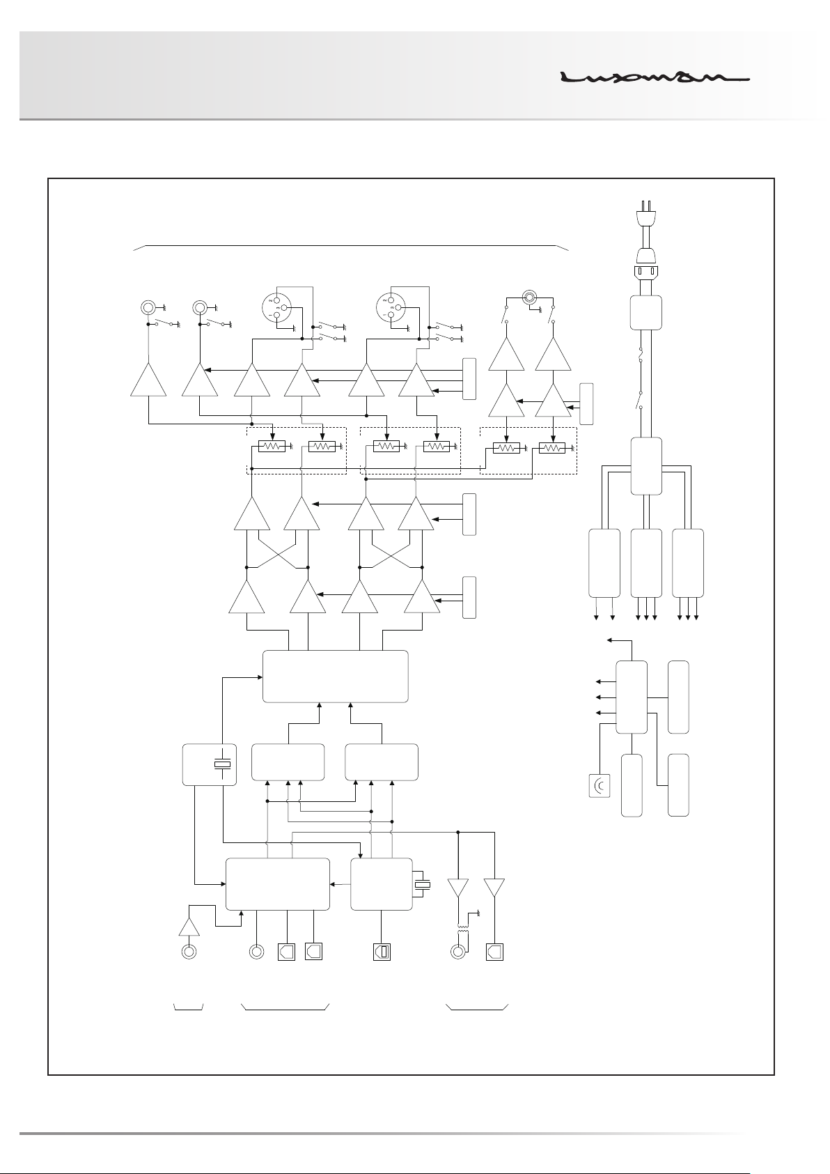
Block Diagram
Digital out
Digital in
Analog in
USB D/A CONVERTER DA-250
Analog out
Unbal. L
Buffer
Unbal. R
Buffer
Buffer
LECUA
–
L.P.F.
I-V
Amp
–
LECUA
–
I-V
Amp
–
Buffer
+
L.P.F.
Bal. R
+
Buffer
–
L.P.F.
I-V
Amp
–
LECUA
REG. ±15V REG. ±15V REG. ±15V
Tr-
H/P
Driver
+Amp
Phones
Tr-
H/P
Driver
+Amp
REG. ±15V
Power Regulator
for Digital Circuit
Line
Filter
FUSE
POWER SW
Power
Transformer
for Audio Circuit
Power Regulator
for Acc. Circuit
Power Regulator
Bal. L
3p: HOT (+)
2p: COLD (-)
1p: GROUND
Buffer
–
+
+
L.P.F.
I-V
Amp
–
DAC
PCM1795
CPU
System Control
Clock
LINE
Sel.
COAX
Data
32kHz~192kHz
PCM9211
DIR / DIT
OPT-1
OPT-2
noise
Generator
low phase-
Data
USB
Controller
Sel.
LPC1822
32kHz~192kHz
USB
2.8224/5.6648MHZ
IR
OPT
COAX
Key
Volime Display
20

Specifications
Format 2-channel, USB D/A converter
Ambient operating
temperature
Audio output
characteristics
Digital input Coaxial digital input 0.2 to 2.5 Vp-p
Line input Input sensitivity/input
Digital output Coaxial digital output: RCA terminal 0.5 Vp-p/75 Ω
Output voltage/output
impedance:
Frequency response: 4 Hz to 20 kHz (+0, –0.5 dB)
Total harmonic distortion: 0.001 %
S/N ratio: 118 dB
Dynamic range: 118 dB
Channel separation: 107 dB
Optical digital input: –14.5 to –24 dBm
USB input:
(Applicable OS)
Sampling frequency: OPT/COAX input: 32 kHz, 44.1 kHz, 48 kHz,
impedance:
Max. input: 2.5 Vrms
Optical digital output: Optical digital terminal –15 to –21 dBm
+5 °C to +35 °C
UNBALANCE terminal (RCA terminal) 2.5 Vrms/300 Ω
BALANCE terminal (XLR terminal) 2.5 Vrms/600 Ω
For DSD (Refer to page 10) 1.2 Vrms (d-1)
1.7 Vrms (d-2)
PHONE terminal (Standard plug) 130 mW + 130 mW (600Ω)
400 mW + 400 mW (32Ω)
200 mW + 200 mW (16Ω)
2 Hz to 50 kHz (+0, –3.0 dB)
Microsoft Windows Vista or later, Mac OS X10.7 or later
USB input: PCM: 32 kHz, 44.1 kHz, 48 kHz,
DSD: 2.8224 MHz, 5.6448 MHz
2.5 Vrms / 6.7 kΩ
88.2 kHz, 96 kHz, 176.4 kHz,
192 kHz
(16 bit, 20 bit, 24 bit)
88.2 kHz, 96 kHz, 176.4 kHz,
192 kHz
(16 bit, 24 bit, 32 bit)
(1 bit)
21
USB D/A CONVERTER DA-250
Attached functions Front panel • Power switch
• Input LED
• PHASE INVERT indicator
• FIX indicator
• Sound volume
Rear panel • AC inlet
• Digital output terminal
(COAX, OPT)
• FIX/VARIABLE selection switch
Accessories • Remote control RD-24
• Owner's Manual
(This document)
• Input selector
• Sampling frequency LED
• SENSITIVITY HIGH indicator
• UNLOCK indicator
• Headphone output terminal
• Digital input terminals
(USB, COAX, OPT 1/OPT 2)
• Analog output terminals
(BALANCE, UNBALANCE)
• Coin-type lithium battery,
CR2025
• Power cable
• Safety cautions
Power supply 230 V ~ (50 Hz)
Power consumption 20 W
Weight (Main unit) 5.4 kg
Dimensions 364 (W) x 81 (H) x 279 (Knobs (14 mm) and terminals (8mm)
included) (D) mm
* Specifications and appearance are subject to change without prior notice.
22

Before Asking for Repair Services
While the unit is used, an unusual phenomenon may be confused as a malfunction for a certain reason. Prior to asking our official sole
distributor of your country for repair services, please check the table below and read the operating instructions for the subsidiary devic-
es. If the cause of the malfunction cannot be identified, please make queries to the purchasing store. When we have once accepted
your request for repair services, inspection fees and traveling expenses may be claimed even though the unit is found to be normal.
Besides, a personal computer such as a PC/Mac connected to the unit and the software that operates on the PC/Mac (operations and
settings included) are not supported.
Problem Cause/Solution Ref. page
No power is supplied even
though the operation switch is
pressed.
No sound is generated. / Sound
volume is too low.
No sound is generated. / Sound
volume is too low. (Digital input)
• Connect the power cable to the AC inlet (AC IN) and the AC outlet
firmly.
• Connect the input devices, amplifier, speakers, and headphones
correctly.
• Set the input selector to the source to be played back. 18
• When you are listening to the sound of headphones or the variable
analog output, adjust the sound volume with the volume control of
the main unit.
• When you are listening to a sound with the fixed analog output,
adjust the sound volume with the volume control of the connected
amplifier.
• Connect digital cables correctly. 15 - 17
• If the USB is selected as an input source, select this unit (DA-250)
as the output destination by configuring the sound setting of a PC/
Mac.
• If the unit (DA-250) cannot be selected even when trying the solution above, reconnect the USB cable.
• If the USB is selected as an input source, adjust the sound volume
by configuring the sound setting of a PC/Mac.
Refer to the instruction manual of
the PC/Mac or the
software in use.
16
15 - 17
18 - 19
18 - 19
The remote control cannot be
operated.
23
• If the USB is selected as an input source, adjust the sound volume
on a player software of a PC/Mac.
• Ensure that this unit supports the sampling frequency and the number of quantization bits of the played back digital signals.
• Ensure that the digital signal unlock indicator (UNLOCK) is not lit up.
(When the digital signal from the digital device is not synchronized
with this unit, the source may not be played back.)
• Operate the remote control within the specified operating range. 13
• Replace the remote control battery with a new one. 13
• The remote control infrared receiver is exposed to direct sunlight or
strong light sources (such as inverter fluorescent lights).
Change the installation place or angle to avoid the exposure to light
sources.
13
8
6

USB D/A CONVERTER DA-250
Problem Cause/Solution Ref. page
An electronic device such as a
television malfunctions.
Hum noises (boon or zzz noise)
are generated.
• Some devices equipped with a wireless remote control receiver may
malfunction when the remote control of this unit is operated. Keep
this unit away from such devices.
• Insert the RCA pin-plugs of the line cables firmly. 16
• Induction noise may be picked up from the power transformer of
another device. Install this unit distantly from the other device.
• When you are listening to the sound of headphones, arrange the
headphone cable and the power cable so that they are not laid too
close.
13
This unit may not work normally when the unit is subject to external influence such as static electricity. In such a case,
the unit can work normally by unplugging the power cable once and plugging it again. If the problem is not solved, please
contact your dealer or our service center.
24

LUXMAN CORPORATION, JAPAN
AG00987E47A
Printed in Japan
 Loading...