


Owner`s Manual
INTEGRATED AMPLIFIER
L-507u

Contents
Precautions ············································································································· 1
Names and Functions ······························································································ 2
Connections ············································································································ 8
Operations ············································································································· 12
How to Use Remote Control ·················································································· 14
Block Diagram ······································································································· 15
Specifications ········································································································ 16
Before Asking for Repair Services ·········································································· 17

INTEGRATED AMPLIFIER L-507u
Precautions
* Note
Wall
* *
*
Installation place
This unit shall be installed in a well�ventilated and effectively
heat�released place.
Especially, installation of this unit where direct sunlight is
present, where the temperature rises excessively high such
as close to a heater, or where it is humid or dusty may cause
a malfunction even if heat is efficiently released. Therefore, do
not install this unit in such places.
Ventilation holes
If the amplifier is installed on a rack or the like, secure ample
space for cooling and leave the door open. Do not pile up
other things on the amplifier and never put articles on it. This
can cause malfunctioning.
Note:
For heat dispersal, do not install this equipment in a confined
space such as a book case or similar unit.
Cautions in connecting speakers
When making speaker system connections, exercise extra
care not to short�circuit between ! and @ of the speaker
terminals and speaker input terminals of this product. If a
large signal is applied to the amplifier with its circuit left short�
circuited, a large current may be passed through the output
circuit and cause a malfunction.
The sound is not generated shortly after
the power supply is turned on.
This amplifier is equipped with a time muting circuit in order
to separate the output circuit. Therefore, no sound is gener�
ated shortly after the power supply is turned on. If the volume
control is moved to a high sound level before the time mut�
ing circuit is canceled, a large sound is suddenly generated.
Please be advised that the volume control shall be set to a
low level at first and adjusted after sound comes out of the
speakers.
Protection circuit
This product is equipped with the protection circuit that is
activated upon detection of overcurrent, abnormally high
temperature, and DC drift to protect the amplifier and speak�
ers. When the protection circuit is activated, the output to the
speaker terminal is shut off and the standby indicator blinks to
show that this product is in the muting state. If the protection
circuit is frequently activated after a lapse of a certain time
and turning on the power again, please consult your dealer.
Precautions in connecting with other
components
When connecting this product to input devices such as a CD
player, a Super Audio CD player, a tuner, and a recorder, be
sure to turn off the power of this product and all other con�
nected devices. Failure to observe this may generate a strong
noise resulting in speaker damage or cause a malfunction.
The pin�plug to be inserted in each input terminal of this prod�
uct shall be pushed in firmly. If the grounding terminal is inad�
equately connected, noises including hum may be generated,
resulting in an adverse S/N ratio.
Batteries
Caution:
Batteries used for remote controller shall not be exposed to
excessive heat such as sunshine, fire or the like.
Repair and adjustments
When repairs or adjustments are needed, please ask your
dealer where you bought the product.
Cleaning
For cleaning, use a piece of soft cloth to wipe the product
such as cleaning cloth available on the market. If the prod�
uct has become remarkably dirty, remove the dirt with soft
cloth absorbing a small amount of neutral detergent, and then
wipe the unit with dry cloth.Do not use a solvent like benzine
or thinner because such a substance can often damage the
exterior.
1

Names and Functions
11121314151617181920
5 7 8 9
106 71 2 43
Front side of main unit
1. Operation switch (stand by/on)
This switch turns the power supply ON/OFF.
When wiring or connection is performed, be sure to turn off
this switch.
2. Operation indicator (OPERATION)
Blinks in the time muting mode when the operation switch
is turned on and lights up when the operation state is ac�
tivated afterward. This indicator blinks when the unit is in
the muting mode or when the volume is adjusted with the
remote control.
3. Input selector (INPUT SELECTOR)
Selects an input device from the devices such as a CD play�
er, a Super Audio CD player and a tuner connected to each
input terminal.
The input selector has 8 positions consisting of bal.line�2,
line�4, line�3, line�2, line�1, rec�1, rec�2, and phono that
correspond to each input terminal on the rear panel. The
knob is rotated to light the input indicator of the input device
to be selected.
4. Input indicator
Lights up at the input device to be selected with the input
selector or remote control.
2

INTEGRATED AMPLIFIER L-507u
5. Phono MC cartridge on/off switch
(phono MC)
Changes the gain level of the equalizer amplifier (amplifier
circuit required to play an analog record).
MC: ON is selected by pressing this switch when MC
(moving coil) type cartridge of low output voltage
is used.
Be aware that the sound volume becomes higher
and unbalanced sound without high frequencies
is generated owing to the impedance when “MC”
is selected during use of the MM type cartridge.
MM: OFF is selected when MM (moving magnet) type
cartridge of high output voltage is used.
6. LINE-2 unbalance/balance selector
(bal. line-1)
Toggles between the unbalance input terminal (LINE�2) and
balance input terminal (BALANCED LINE�1) when the input
selector is set to the line�2 position.
: BALANCED LINE�1 is selected.
: LINE�2 is selected.
7. Power meters
The left meter reads the output of the L channel, and the
right meter reads the output of the R channel.
The meters read the level in decibels.
The meters light when the power is on.
8. Remote sensor (remote sensor)
Receive signals from the accessory remote control.
9. Standby indicator (stand by)
Lights when the AC plug is plugged into a wall socket and
the operation switch is set to off.
This indicator turns off when the AC plug is disconnected
from the wall socket or the operation switch is set to on. This
indicator blinks when the protection circuit is activated.
10. Volume control (VOLUME CONTROL)
Adjust the sound volume. Sound is not generated when this
control is rotated counterclockwise to the end, and then,
the sound volume gradually becomes higher when the con�
trol is slowly rotated clockwise.
3

Names and Functions
11121314151617181920
5 7 8 9
106 71 2 43
Front side of main unit
11. Separate switch (separate)
Separates the pre�amplifier and main�amplifier each other.
OFF: Uses this unit as a normal pre�main amplifier.
ON: Feeds external signals from the MAIN IN terminal
on the rear panel to the main�amplifier section.
When the separate switch is set to on, the volume control
of this unit cannot adjust the volume of the speakers con-
nected to this unit. Volume adjustment shall be performed
at the input device side such as the control amplifier con-
nected to the MAIN IN terminal.
Entry of direct output into the MAIN IN terminal from a CD
player or other devices that cannot adjust sound volume
constantly provides a full power state and accordingly re-
sults in the risk of speaker damage.
For such input devices, be sure to use a control ampli-
fier equipped with sound volume adjustment function as
a relay, generate sound through the speakers with volume
lowered, and adjust the volume to your favorite level.
12. Subsonic (subsonic)
Cuts ultra�low frequencies out of audible range to pre�
vent ultra�low range noise from adversely affecting audible
range.
This function is significantly effective especially when a re�
cord is warped or a woofer is shaking owing to ultra�low
range vibration.
OFF: Subsonic off
ON: Subsonic on
13. Line straight (line straight)
Enhances the purity of the sound quality by bypassing the
balance control circuit, tone control circuit, or the like.
OFF: Line straight off/bypass off
ON: Line straight on/bypass on
When the line straight switch is set to on, the balance con-
trol and tone control cannot be adjusted and the mode se-
lector does not function.
4

INTEGRATED AMPLIFIER L-507u
14. Balance (BALANCE)
Adjusts the balance of sound volume between right and left
channels.
Rotating this switch counterclockwise causes the left sound
volume to be enhanced, and rotating the switch clockwise
causes the right sound volume to be enhanced.
This switch shall be set to the center position under normal
conditions and rotated to make adjustment if necessary.
When the line straight switch is set to on, this switch does
not function.
15. Tone control for treble
(TONE CONTROL, treble)
Controls to change the frequency characteristics in the
high�frequency range.
When this switch is set to the center position, flat frequency
characteristic is obtained. Rotating the switch clockwise
causes the high�frequency range to be enhanced, and rotat�
ing the switch counterclockwise causes the high�frequency
range to be attenuated.
When the line straight switch is set to on, this switch does
not function.
16. Tone control for bass
(TONE CONTROL, bass)
Controls the frequency characteristics in the low�frequency
range.
When this switch is set to the center position, flat frequency
characteristic is obtained. Rotating the switch clockwise
causes the low�frequency range to be enhanced, and rotat�
ing the switch counterclockwise causes the low�frequency
range to be attenuated.
When the line straight switch is set to on, this switch does
not function.
18. Speaker selector (SPEAKERS)
Selects either of 2 speaker systems, A or B, located at the
rear panel.
off: Activates only headphones. No sound is gener�
ated from any speakers.
A: Selects the A system speaker terminal.
(center)
B: Selects the B system speaker terminal.
A+B: Simultaneously activates both A and B system
speakers. When both speaker terminals are si�
multaneously used, select speakers with imped�
ance of 8 ohms or more because both output
terminals are connected in parallel.
19. Recording selector (REC SELECTOR)
Selects an input source to be recorded and sends record�
ing signals to the recorder connected to this unit.
When both of the input selector (INPUT SELECTOR) and
the recording selector (REC SELECTOR) are set to the line-
2 position, the LINE-2 unbalance/balance selector(bal.line-
1) toggles the recorder output terminals on the rear be-
tween the unbalance input terminal (LINE-2) and balance
input terminal (BALANCED LINE-1).
When you need not toggle an input source to be recorded
(especially when a recorder connected to the recorder out-
put terminals is recording), do not operate this switch.
20. Headphone jack (phones)
Is used to listen to sound with use of stereo headphones.
Insert the headphone plug into this output jack. Even when
the plug is inserted, signals to the speaker output terminal
are not interrupted. Accordingly, to listen to sound with only
use of headphones, set the speaker selector to off.
17. Mode selector (MODE SELECTOR)
Changes the output mode.
stereo: Provides normal stereophonic reproduction.
(center)
mono: Mixes the signals from right and left channels.
left ch: Reproduces the signals only from the left channel
with use of both speakers.
right ch: Reproduces the signals only from the right chan�
nel with use of both speakers.
5
Names and Functions
21
2728
22 23 24 25 26
29
31
30
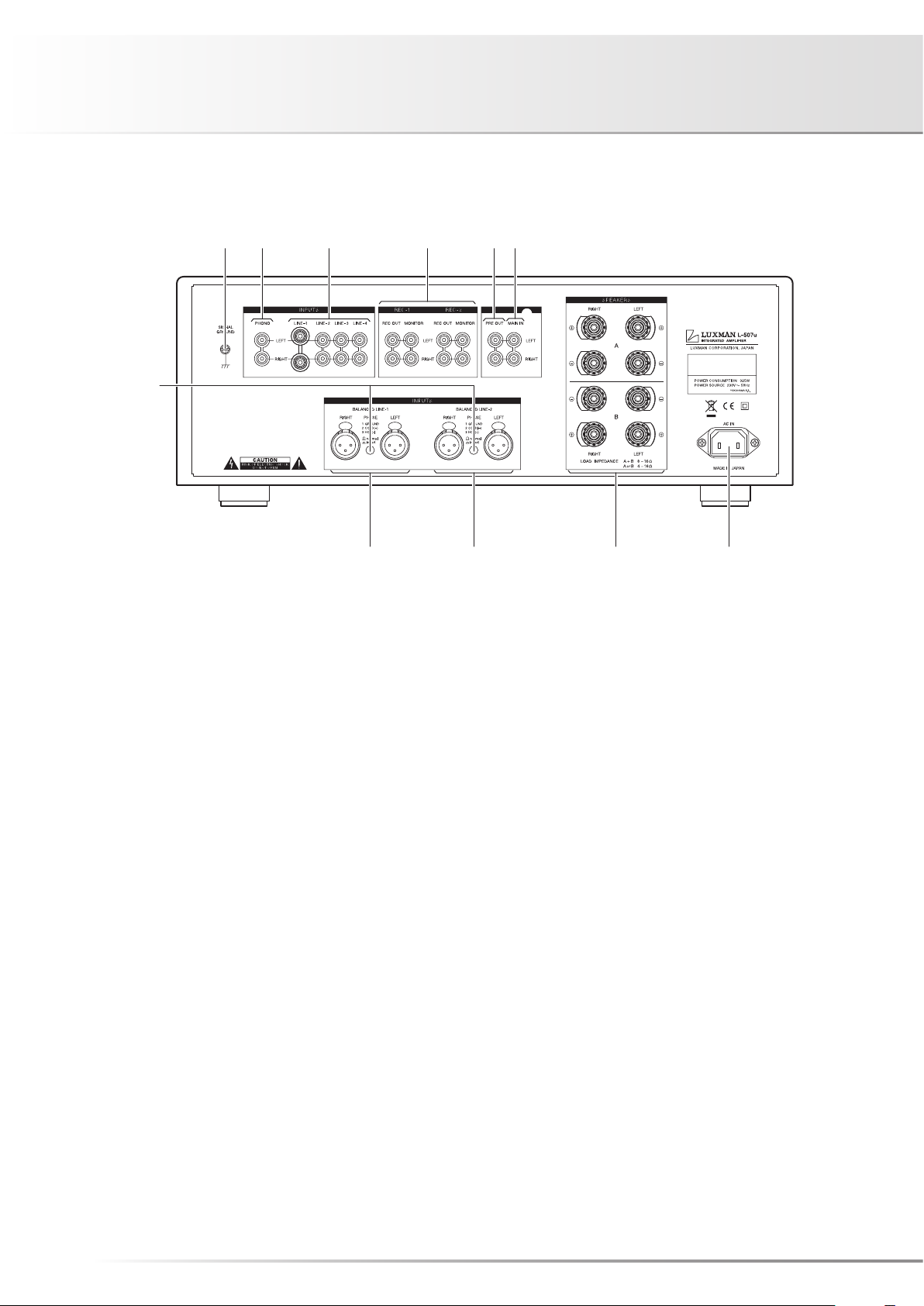
Rear side of main unit
21. Signal ground (ground terminal)
(SIGNAL GROUND)
Is a signal ground terminal for devices to be connected to
this unit. This terminal is used to reduce noise when other
devices are connected. This terminal is designed not for
grounding for safety.
22. Phono input terminal (PHONO)
Is an input terminal to connect an analog record player.
23. LINE-1, LINE-2, LINE-3, and LINE-4
input terminals (unbalance)
(LINE-1, LINE-2, LINE-3, LINE-4)
Are used for high�level signal inputs from a CD player, a
Super Audio CD player, a tuner, a video deck, a TV, and
other such devices. The input sensitivity is 180 mV, and the
impedance is 42 kohms. These input terminals offer the
same functions.
24. Recorder input/output terminals
(REC-1, REC-2)
Connect the audio input/output of a recorder. The audio
input of a recorder is connected to REC OUT, and the audio
output of a recorder is connected to MONITOR.
25. Pre-out terminals (PRE OUT)
Provides the output of the preamplifier section.
A Bi�AMP connection can be performed with a combination
of an external power amplifier because this terminal always
provides output regardless of the separate switch setting.
26. Main in terminals (MAIN IN)
Provide input to the main�amplifier section when the pre�
amplifier and main�amplifier are separated.
6

INTEGRATED AMPLIFIER L-507u
27. AC inlet (AC IN)
General type terminal
Connects the accessory power cable is connected.
The power should be obtained from a 230V AC outlet.
28. Speaker terminals (SPEAKERS)
Connect speaker systems.
The right speaker terminal shall be connected to the RIGHT
side, and the left speaker terminal shall be connected to the
LEFT side in consideration of the polarity.
29. LINE-2 input terminals (balance)
(BALANCED LINE-2)
Are the balance type input terminals of the LINE level for an
XLR connector (Cannon connector).
30. LINE-1 input terminals (balance)
(BALANCED LINE-1)
Are the balance type input terminals of the LINE level for an
XLR connector (Cannon connector).
When the input selector is set to LINE�2 and the bal. line�1
switch is pressed, both of which are located on the front
panel, the input from this terminal is reproduced.
31. Phase inverters (PHASE)
Change the phase when the balance input terminal is used.
The phase shall be corresponding to the phase of the input
device.
Normal position ① GROUND
② COLD
③ HOT
Invert position ① GROUND
② HOT
③ COLD
7

Connections
RECORDER
SPEAKER SYSTEM(A
)
L R L R
SPEAKER SYSTEM(B
)
ANALOG PLAYER
–+ –+ –+ –+
CD/SACD PLAYER
CD/SACD PLAYER
8

INTEGRATED AMPLIFIER L-507u
How to connect Power Supply
Use an accessory power cable and insert the AC plug in a
230V AC outlet on the wall in the room where the unit will
be installed.
How to connect CD player, Super Audio
CD player, tuner, or other devices
Connect between the output terminals of a CD player, a
Super Audio CD player, a tuner, or other such input devices
and the LINE�1 input terminals of this unit with 2 (R and L)
pin�plug cables or balanced cables.
For LINE�2, LINE�3, and LINE�4 input terminals, connection
in the same fashion as the LINE�1 terminals provides the
reproduction likewise.
How to connect speakers
Connect the left�channel speaker to the LEFT SPEAKER
terminal of this unit and the right�channel speaker to the
RIGHT SPEAKER terminal.
Securely connect the ! terminal of the speaker system to
the speaker terminal ! (red) of this unit, and the @ terminal
of the speaker system to the speaker terminal @ (black) of
this unit.
If the ! and @ terminals are reversely connected to either
of the right and left speaker systems, the acoustic phases
of the sound reproduced from the right and left speaker
systems are also reversed. In such a case, be aware that
the sound level in the low range will be reduced and the
acoustic stability will worsen, thus failing in normal stereo
playback.
9

Connections
RECORDER
SPEAKER SYSTEM(A
)
L R L R
SPEAKER SYSTEM(B
)
ANALOG PLAYER
–+ –+ –+ –+
CD/SACD PLAYER
CD/SACD PLAYER
10

INTEGRATED AMPLIFIER L-507u
How to connect record player
Connect between the output terminal of an analog record
player and the PHONO terminal of this unit with 2 (R and L)
pin�plug cables. For some types of players, the ground wire
from the phono motor or the tone arm should be connected
to the ground terminal of this unit.
The phono equalizer of this unit uses the MM or MC car�
tridge. If an MC cartridge with low output voltage is used,
set the phono MC switch on the front panel to on.
The output from a record player equipped with a phono
equalizer or from an independent phono equalizer shall be
connected to the LINE input terminal of this unit.
How to connect recorder
1. Connection to monitor terminal
(playing)
Connect between the line output terminals (LINE OUT) of a
recorder and the monitor terminals of this unit with pin�plug
cables in consideration of R and L. Now, setting the input
selector to rec�1 or rec�2 provides playback.
How to connect PRE OUT/MAIN IN terminal
Either the pre�amplifier or main�amplifier can be separately
used.
When the pre�amplifier or main�amplifier is separately used,
set the separate switch on the front panel to on.
When only the pre�amplifier is used, connect the PRE OUT
terminal of this unit to the input terminal of another power�
amplifier, and when only the main�amplifier is used, connect
the MAIN IN terminal of this unit to the output terminal of
another power�amplifier.
When this amplifier is used without separating between
pre-amplifier and main-amplifier, set the separate switch
on the front panel to off, or no sound is generated.
2. Connection to REC OUT terminal
(recording)
When the sound source from the various input devices is
reproduced, which are connected to the PHONO or LINE
terminals of this unit, setting the recording selector to the
source to be recorded allows users to provide the REC OUT
terminal with the signal. Connection between the REC OUT
terminal of this unit and the line input terminals (LINE IN) of
the recorder with pin�plug cables is required for recording
on the recorder. After the connection, you can enjoy listen�
ing to the sound from the speaker system and record the
sound at the same time. These output signals for recording
are not affected by the control functions such as the volume
control and tone control functions.
When both of the input selector and the recording selector
are set to the line-2 position, the LINE-2 unbalance/bal-
ance selector toggles the recorder output terminals on the
rear between the unbalance input terminal (LINE-2) and
balance input terminal (BALANCED LINE-1)
When you need not toggle an input source to be recorded
(especially when a recorder connected to the recorder out-
put terminals is recording), do not operate this switch.
11

Operations
Before operation
1. Ensure that the connections are correctly performed.(Nor�
mal playback cannot be achieved with wrong connection
of R, L, !, or @.)
2. When the power is toggled between on and off or the in�
put selector is changed over, set the volume control to the
minimum position in advance.
Playback procedures
1. Press the operation switch after ensuring that the volume
control is set to the minimum position.
2. Select a source to be reproduced with the input selector.
3. Adjust the sound level with the volume control.
4. Operate the line straight switch, balance control, or tone
control according to the reproduced source.
How to operate line straight switch
The line straight switch is used to play sound with the short�
est signaling route for enhancing the purity of the source se�
lected with the input selector.
When this switch is set to on, the balance control, tone con�
trol, and mode are bypassed.
How to operate balance control
The balance control allows users to adjust the balance of
sound volume between right and left channels.
When the balance adjustment is not required, the balance
control is set to the center position.
When the line straight switch is set to on, the balance control
does not function.
How to operate the tone control
This unit has the tone control function for the low�frequency
and high�frequency ranges.
The low�frequency range type works in the 300 Hz or lower.
The tone control is set to flat frequency characteristic at the
center position. Rotating the control clockwise causes the
low�frequency range to be enhanced, and rotating the con�
trol counterclockwise causes the low�frequency range to be
attenuated.
The high�frequency range type works in the 3 kHz or higher.
As with the low�frequency range type, the tone control is set
to flat frequency characteristic at the center position.
Rotating the control clockwise causes the high�frequency
range to be enhanced, and rotating the control counterclock�
wise causes the high�frequency range to be attenuated.
For both the low�frequency and high�frequency ranges, the
right and left channels interlockingly function.
When the line straight switch is set to on, the tone control
does not function.
How to record a source
1. Select a source to be recorded with the recording selec�
tor.
* For dubbing:
Selection of rec�1; rec�1 �> rec�2 (dubbing direction)
Selection of rec�2; rec�2 �> rec�1 (dubbing direction)
2. Play the source to be recorded and set the recorder to the
recording state.
* Operation of the tone control or balance control does not
affect the recording signals.
* Reproduction of the source selected by the input selector
can be enjoyed without effect on recording because the
recording selector and input selector independently oper�
ate.
* The recording selector works when the power is on.
12

INTEGRATED AMPLIFIER L-507u
Procedure of timer-controlled recording
1. Turn on the operation switch to activate this unit.
2. Select a source to be recorded under timer control with
the recording selector.
3. Perform time setting for start and stop times with your
timer.
4. Refer to the operating instructions of the timer and other
connected devices for further information.
If the volume control is not set to low levels, the source se-
lected with the input selector may be reproduced from the
speakers. Be sure to set the volume control to a low level.
Procedure of timer-controlled playing
1. Turn on the operation switch to activate this unit.
2. Select a source to be reproduced under timer control with
the input selector.
3. Adjust the volume level with the volume control.
4. Perform time setting for start and stop times with your
timer.
5. Refer to the operating instructions of the timer and other
connected devices for further information.
Memory
This unit stores the following items when the power is off:
Item To be stored
INPUT Selected source
display on/off on/off
Memory reset
The following operations restore all the settings to the factory
defaults.
(1) Turn off the power of this unit.
(2) Hold down the operation switch for 5 seconds or more,
and the power state switches from on to off.
That’s all for reset.
Factory default
Item Default
INPUT LINE�1
display on/off on/off
13

33
(1)
(10)
(3)
32
30°30°
Effective distance: approx. 5 m
How to Use Remote Control
Remote control (RA-9)
32. Mute switch
Activates the mute function and blinks the power�on indica�
tor resulting in no sound generated. Pressing this button
again to set the mute function to off allows sound to be
generated.
Remote control
The remote control shall be aimed at the remote sensor of
this unit within the specified angle range shown in the illus�
tration when used.
Dry cell
[How to load batteries]
1. Put your finger on the battery cover claw located behind the
remote control. The battery cover can be opened by sliding it
downwards.
2. Put 2 AAA batteries in the battery case as shown in the illus�
tration.
3. Close the battery cover.
33. Display (display on/off)
Turns off the meter lights. Pressing this switch turns off the
meter lights.
Pressing this switch again turns on the meter lights again.
* The value in parentheses indicates the number in “Names
and Functions”.
14
* When the batteries start to lose power, the effective dis�
tance becomes shorter or the unit does not function even
though the switch is pressed. In such a case, both of the
batteries shall be replaced with new ones at the same
time.
* If the remote control is not used for a long time, the batter�
ies shall be removed from the case.

INTEGRATED AMPLIFIER L-507u
Block Diagram
MAIN
IN
PRE
OUT
MODE
BALANCE
PRE AMP
LINE
STRAIGHT
SUBSONIC
MUTE
METER
METER
AMP
SPEAKER SELECTOR/
PROTECTOR
DC.
OC.
TEMP.
FOR
PROTECTOR
FOR
μ-COM
FOR
EQ AMP
TONE AMP
PRE AMP
POWER
TRANSFORMER
BACKUP
TRANSFORMER
FUSE
POWER
REG
REG
REG
REG
FOR
FINAL
DRIVER
REG
+B1
–B1
–B2’
–B2
+B2
A-SPEAKERS
B-SPEAKERS
PHONES
+ –
+ –
+ –
FOR
MAIN
AMP
ODNF
B2
L
B1
L
B1
R
B2
R
PHONO
LINE-2
LINE-1
LINE-3
LINE-4
EQ
AMP
RIAA
MM/MC
BALANCED
LINE-1
PHASE
BAL/UNBAL
AMP
1 2
3
PHASE
BALANCED
LINE-2
BAL/UNBAL
AMP
1 2
3
INPUT
SELECTOR
REC
SELECTOR
TONE
AMP
TREBLE/BASS
CONTROL
REC SELECTOR
μ-COM
INPUT SELECTOR
stand by/on
SWITCH
REMOTE
SENSOR
LINE-1
BAL/UNBAL
REC OUT
MONITOR
REC OUT
rec-2
MONITOR
rec-1
15

Specifications
Continuous power output 110 W + 110 W (8 Ω)
200 W + 200 W (4 Ω)
Total harmonic distortion 0.015% (8 Ω, 1 kHz both channels simultaneous drive, line straight on)
0.22% (8 Ω, 20 Hz to 20 kHz both channels simultaneous drive, line straight on)
Pre-amplifier
Input sensitivity/input impedance
Main-amplifier
Input sensitivity/input impedance
Output voltage RECORDER : 180 mV
S/N ratio PHONO (MM) : 91 dB or more
Frequency response PHONO (MM) : 20 Hz to 20,000 Hz (±0.5 dB, line straight on)
Tone control
PHONO (MM) : 2.5 mV / 47 kΩ
PHONO (MC) : 0.3 mV / 100 Ω
LINE : 180 mV / 42 kΩ
RECORDER : 180 mV / 42 kΩ
BAL. LINE : 180 mV / 79 kΩ
MAIN�IN : 1.05 V / 51 kΩ
PRE�OUT : 1 V
(IHF�A weighted, 5 mV input, line straight on)
PHONO (MC) : 75 dB or more
(IHF�A weighted, 0.5 mV input, line straight on)
LINE : 107 dB or more
(IHF�A weighted, input shorted, line straight on)
PHONO (MC) : 20 Hz to 20,000 Hz (±0.5 dB, line straight on)
LINE : 20 Hz to 100,000 Hz (–3 dB or less, line straight on)
Max. amount of change
TREBLE : ±10 dB at 10 kHz
BASS : ±10 dB at 100 Hz
Damping Factor : 190
Accessories · Remote controller RA�9 · Power cable
· Owner’s Manual · Safety cautions
· size “AAA” batteries (2 pieces)
Power supply voltage 230 V AC (50 Hz)
Power consumption 325W
1.5 W (at standby), 82 W (at no input)
Max. external dimensions 467 (W) × 179 (H) × 430 (D) mm
Weight 22.5kg (main unit only)
* Specifications and appearance are subject to change without notice.
16

INTEGRATED AMPLIFIER L-507u
Before Asking for Repair Services
While the unit is used, an unusual phenomenon may be confused as a malfunction for a certain reason. Prior to asking us
for repair services, please check the table below and read the instruction manual for the subsidiary devices. If the cause of
the malfunction cannot be identified, please contact your dealer.
Problem Cause Solution
No power is supplied even
though the operation switch is
pressed ON.
No sound is generated. · The volume control is set to the minimum
No sound comes out on one
side.
Humming sound (boon or zzz
noise) is generated.
· The power plug is disconnected from the
wall outlet, or it is not completely inserted.
· The power plug is disconnected from the
AC inlet, or it is not inserted completely.
level.
· The input selector is not set in the playback
source position.
· Cable connections are incomplete. · Make cable connections securely.
· The output level of the input device is set to
the minimum position.
· The separate switch is set to on. · Set the separate switch to off.
· The balance control is fully rotated. · The balance control shall be set to the cen� The balance control shall be set to the cen�
· The connecting cable is not connected on
one side only.
· The ground side of the pin�plug cable has
no contact with the terminal.
· Insert the power plug in the wall outlet se� Insert the power plug in the wall outlet se�
curely.
· Insert the power plug in the AC inlet se� Insert the power plug in the AC inlet se�
curely.
· Rotate the volume control clockwise to ad� Rotate the volume control clockwise to ad�
just the sound volume.
· Set the input selector in the playback source
position.
· Adjust the output level.
ter position under normal conditions.
· Make cable connections securely.
· Make connections securely so that the
ground side of the pin�plug cable makes
contact with the terminal.
No effect of tone control or bal�
ance control is observed.
The light of the power meter is
not turned on.
· The ground wire of the record player is not
connected.
· Connections or mounting conditions are in� Connections or mounting conditions are in�
complete between the cartridge and shell,
or between the shell and tone arm of the
record player.
· The line straight switch is turned on. · When tone control or balance control is
· The display switch is set to off. · Set the display switch of the remote control
· Connect the ground wire of the record play�
er to the GND terminal.
· Connect (or mount) the cartridge, shell, and
tone arm securely.
used, the line straight switch shall be set to
off.
to on.
17

LUXMAN CORPORATION, JAPAN
AG00987C68A
Printed in Japan
 Loading...