


CONTROL AMPLIFIER
C-700u
Owner`s Manual

Contents
Precautions ············································································································· 1
Features of This Unit ································································································ 2
Names and Functions ······························································································ 4
Connections ·········································································································· 12
Operations ············································································································· 16
How to use Remote Control ·················································································· 18
Block Diagram ······································································································· 24
Specifications ········································································································ 27
Before Asking for Repair Services ·········································································· 28
CONTROL AMPLIFIER C-700u
Precautions
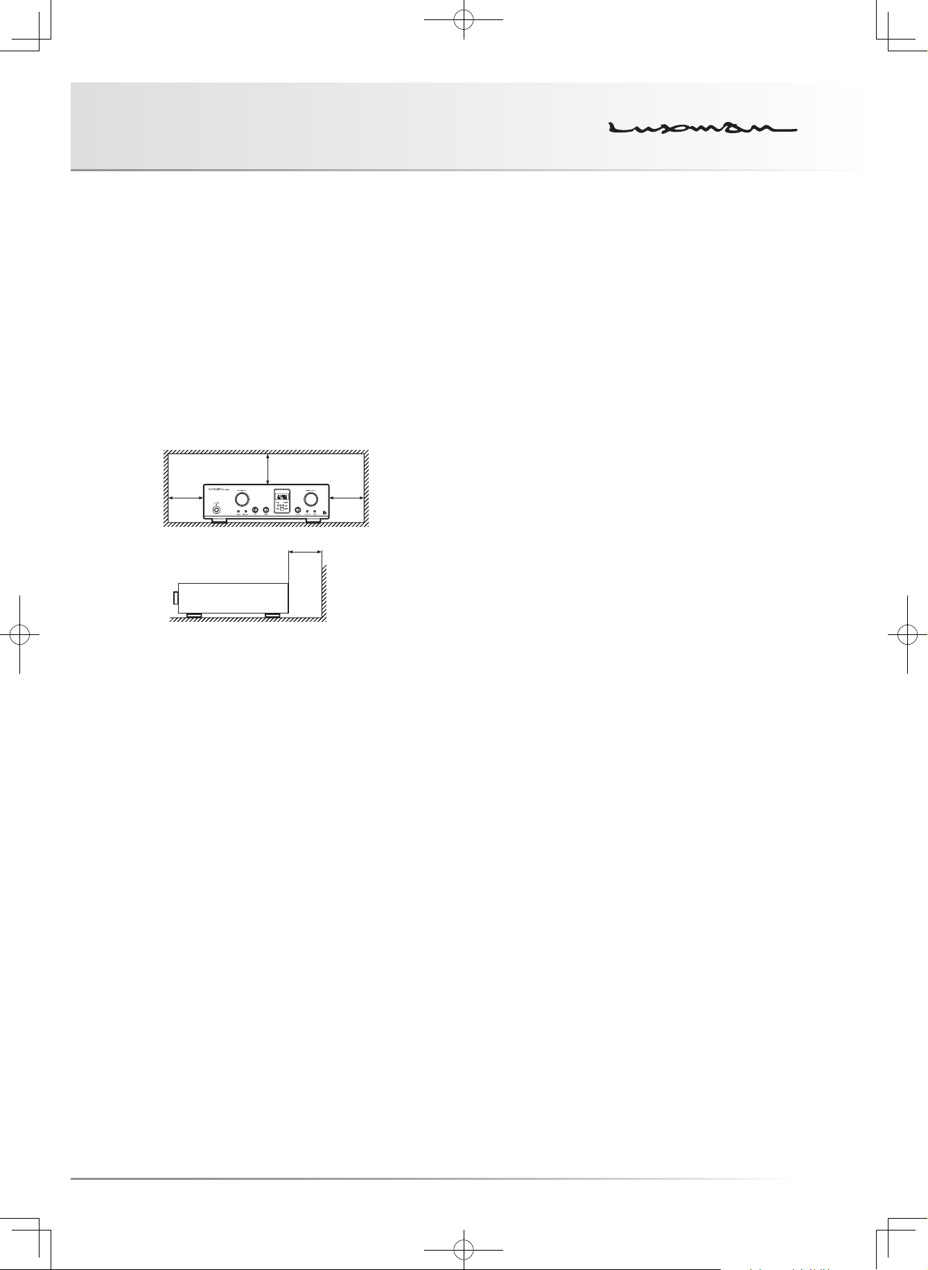
Installation place
Install this unit in a location where good ventilation and heat
radiation is assured.
Especially, installation of this unit where direct sunlight is
present, where the temperature rises excessively high such
as close to a heater, or where it is humid or dusty may cause
a malfunction even if heat is efficiently released. Therefore, do
not install this unit in such places.
Note:
For heat dispersal, do not install this equipment in a confined
space such as a book case or similar unit.
* Note
* *
*
Wall
Batteries
Caution:
Batteries used for remote controller shall not be exposed to
excessive heat such as sunshine, fire or the like.
Repair and adjustment
When repair and adjustments are needed, please ask the
dealer where you bought the unit.
Cleaning
For cleaning, use a piece of soft cloth to wipe the unit such as
cleaning cloth. When the dirt is hard to remove, use a small
amount of neutral detergent to wipe, and then wipe the unit
with dry cloth. Do not use a solvent like benzine or thinner
because such a substance can often damage the exterior.
Precautions in connecting with other
components
When connecting this unit to input/output devices, be sure to
turn off the power switches of this unit and all other connect-
ed units. Failure to observe this may generate a strong noise
resulting in speaker damage or a malfunction.
The pin-plugs to be inserted in the input and output terminals
of this unit shall be pushed in firmly. If the grounding termi-
nal is inadequately connected, noises including hum may be
generated, resulting in an adverse S/N ratio.
The sound is not generated shortly after
the power supply is turned on.
This amplifier is equipped with a time muting circuit in order to
separate the output circuit. Therefore, no sound is generated
shortly after the power supply is turned on.
If the volume control is set to a high sound level before the
time muting circuit is canceled, a large sound is suddenly
generated. Please be advised that the volume control shall be
set to a low level at first and adjusted after the sound comes
out of the speakers.
1

Features of This Unit
LECUA1000 — LUXMAN Electric
Controlled Ultimate Attenuator 1000
Application of the system to obtain attenuation by combining
2 fixed resistances connected in series has improved the effi-
ciency of the LECUA1000 attenuator used in C-1000f.
The shortest signaling route has been achieved by the ampli-
fier circuit thanks to the 3D structure of the mounting boards.
Controlling LECUA1000 to the level equal to the volume po-
sition detected by a microprocessor has achieved the oper-
ation feeling similar to our conventional sliding-type volume
controls.
ODNF - Only Distortion Negative Feedback -
The amplification feedback circuit that has acquired the high-
speed primary slew rate and ultra-wide bandwidth by feeding
back only distortion components generated during amplifica-
tion for the main amplifier to maintain the pure sound quality
that is almost non-feedback.
With ODNF’s latest version 4.0, in the amplification circuit,
the first stage is 4-parallelized and the second stage is con-
nected with Darlington. Due to these improvements, the low
impedance and high S/N ratio of the transmission circuit have
become possible.
In addition, the input stages of the error detection circuit are
3-parallelized to improve distortion and noise.
High-inertia power supply
High-inertia power supply circuit that combines a large-ca-
pacity OI-core-type power transformer with customizable ca-
pacitor blocks.
Schottky barrier diode
In the power supply rectifier circuit, schottky barrier diode
manufactured by Nihon Inter Electronics Corporation that has
less switching noises and higher conversion efficiency to the
DC voltage is applied.
LUXMAN’s original OFC wires
Our original OFC wires are used in the internal wiring to
achieve smooth signal transmission thanks to the spiral wrap
shielding on each core and the non-plating processing on the
core wire.
Loopless chassis
The independent construction of a loopless chassis structure
eliminates the rise of increased ground impedance caused by
chassis current.
AC inlet
This inlet enables the connection with an external power ca-
ble.
2

CONTROL AMPLIFIER C-700u
Zoom function
When the ZOOM button on the remote control is pressed, the
current volume level is enlarged on the display.
Remote control (RA-22)
The remote control is encased in aluminum. Tactile switches
will satisfy users with “clicking” key touch.
Dimmer function
The brightness of the display window can be switched over
in 4 steps.
Round pattern board
In consideration of the delicate audio signal flow, circuit
boards are round-patterned for the smooth current flow.
Input/output terminals
Introduction of 18 mm pitch RCA input terminals and an XLR
terminal manufactured by Neutrik allows even a high-perfor-
mance line cable with large plug to be connected.
Cast-iron insulator
The gradation cast-iron insulator that clears unnecessary ex-
ternal vibration and strongly supports the weight of this unit
is equipped.
External pre-input terminal
External pre-input terminal is equipped to select an input from
external pre-amplifier or AV amplifier etc.
Selector relay
Selector relay with high sound quality used in Luxman ampli-
fiers enhances the separation and crosstalk performances.
3

Names and Functions
67891213 1011
51 2 43
Front panel
1. Operation switch (OPERATION)
Turns this unit from the standby state to operation state.
When the main power switch on the rear panel is turned on
to set this unit to the standby state and this switch is turned
on, this unit is set to the operation state.
Pressing this switch again at the operating state turns the
unit to the standby state.
2. Operation indicator (OPERATION)
Blinks during warm-up when the operation switch is turned
on and lights up when the operation state is activated af-
terward.
3. Input selector (INPUT SELECTOR)
Selects the unbalanced input terminal or balanced input ter-
minal, both of which are located on the rear panel.
• Input transition by rotating clockwise:
→LINE-2→LINE-3→LINE-4→LINE-5→BAL LINE-1
LINE-1
→BAL LINE-2→LINE-1...
• Input transition by rotating counterclockwise:
→BAL LINE-2→BAL LINE-1→LINE-5→LINE-4→
LINE-1
LINE-3→LINE-2→LINE-1 …
Factory default: LINE-1
During input selecting operation, input/output muting circuit
is in operation and the unit will be on mute.
4. Display window
Displays the operation status of this unit.
This display window is composed of 8 indicators, input dis-
play, and volume display.
5. Volume control (VOLUME CONTROL)
Adjusts the sound volume.
When this control is rotated counterclockwise to the end,
the unit is on mute. The sound volume gradually becomes
higher when the control is rotated clockwise as follows:
→-87 dB→-86 dB→..→0 dB in steps of 1 dB.
mute
4

CONTROL AMPLIFIER C-700u
6. External pre switch (EXT PRE)
Input selector switch to select the external pre-input termi-
nal (EXT PRE) on the rear panel
ON: Outputs sound signals connected to EXT Pre terminal
(pre-amplifier, AV amplifier etc.) directly.
OFF: Plays back a sound source selected by the input se-
lector.
Holding down the switch for approx. 1 second toggles the
external pre switch ON and OFF.
When the external pre switch is set to ON, the external pre
indicator lights up.
When the main power switch is turned off or this unit is
in the standby state, external pre-input signals are always
provided from the unbalanced output terminal regardless of
this switch setting. The input signals connected to the ex-
ternal pre-input terminal are not provided from the balanced
output terminal.
When the external pre switch is set to ON, the volume con-
trol of this unit cannot adjust the sound volume.
Volume adjustment shall be performed at the input device
side such as the pre-amplifier connected to the external
pre-input terminal.
If a device that has no volume adjustment function such as
a CD player is connected to the external pre-input terminal,
the volume control of this unit cannot function, and there-
fore, sudden loud sound may be generated when the exter-
nal pre-input is selected, which may cause hearing loss or
damage to the speakers.
For such input devices, be sure to use a pre-amplifier or the
like equipped with the sound volume adjustment function.
After checking the sound through the speakers with volume
lowered, adjust the volume to your favorite level.
When changing the connected devices, be sure to turn off
the main power switch or set the unit to the standby state.
7. Output mode selection switch
(OUTPUT MODE)
Selects an output mode from the following 3 kinds: unbal-
anced output, balanced output, and both (unbalanced +
balanced) output.
By pressing this switch, the output changes as follows: UN-
→BAL→BOTH→UNBAL ...
BAL
• Unbalanced output (UNBAL)
Sound comes out from LINE-1 and LINE-2.
• Balanced output (BAL)
Sound comes out from BAL LINE-1 and BAL LINE-2.
• Both output (BOTH)
The unbalanced outputs, LINE-1 and LINE-2, and the
balanced outputs, BAL LINE-1 and BAL LINE-2, provide
audio output.
Factory default: Unbalanced output (UNBAL) mode
The input/output muting circuit is activated to mute sound
during selecting an output mode.
Every output mode can store preset values, respectively.
Refer to the descriptions about presetting on pages 20 to
21 for presetting.
8. Balance control (BALANCE)
Adjusts the balance of sound volume between right and left
channels.
Rotating this control counterclockwise makes the left sound
volume enhanced, and rotating this control clockwise
makes the right sound volume enhanced.
This control shall be set to the center position under normal
conditions, and rotate to make adjustment if necessary.
The adjustable value for right/left balance is up to -6 dB for
right and left each.
9. Remote sensor (REMOTE)
Receives signals from the remote control.
5

Names and Functions
67891213 1011
51 2 43
Front panel
10. Tone control for treble
TONE CONTROL (TREBLE)
Controls the frequency characteristics in the high-frequency
range.
When this control is set to the center position, flat frequency
characteristic is obtained. Rotating this control clockwise
makes the high-frequency range enhanced, and rotating
this control counterclockwise makes the high-frequency
range attenuated.
This control does not function when the line straight switch
is set to ON.
11. Tone control for bass
TONE CONTROL (BASS)
Controls the frequency characteristics in the low-frequency
range.
When this control is set to the center position, flat frequency
characteristic is obtained. Rotating this control clockwise
makes the low-frequency range enhanced, and rotating this
control counterclockwise makes the low-frequency range
attenuated.
This control does not function when the line straight switch
is set to ON.
12. Line straight switch (LINE STRAIGHT)
This switch is used to increase the purity of the sound qual-
ity by bypassing (skipping) the tone control circuit.
By pressing this switch, line straight setting toggles be-
tween ON and OFF repeatedly.
The line straight indicator lights up when the line straight
switch is set to ON.
When the line straight switch is set to ON, the tone control
and loudness do not function.
13. Monitor switch (MONITOR)
This switch is to activate the monitor input terminal.
ON: Plays back a source from the recorder.
OFF: Plays back a sound source selected by the input se-
lector.
By pressing this switch, the monitor switches from on to off.
6

CONTROL AMPLIFIER C-700u
7

Names and Functions
6 75 9
1
324
11108
Display window
1. Input indicator (IN:)
Displays the input terminal selected by the input selector or
the remote control.
2. Volume indicator (VOL:)
Indicates the current volume level in steps of 1 dB.
• “- -” shows the mute state. No sound is generated.
• The minimum volume level shown is “–87 dB”, and the
maximum volume level shown is “0 dB”.
3. Loudness indicator (LOUDNESS)
Lights up when the loudness switch on the remote control
is set to ON.
4. Balance indicator (BAL)
Lights up when the balanced output terminal is selected for
the output mode.
5. Standby indicator (STAND BY)
Lights up when the main power switch on the rear panel is
turned on and the operation switch is turned off.
When the operation switch is turned on or when the main
power switch is turned off, this indicator turns off.
6. Unbalance indicator (UNBAL)
Lights up when the unbalanced output terminal is selected
for the output mode.
7. Remote sensor (REMOTE)
Receives signals from the remote control.
8

CONTROL AMPLIFIER C-700u
8. Rec out indicator (REC)
Lights up when the rec out is activated by the preset func-
tion of the remote control.
9. Balanced phase inversion indicator
(BAL INVERT)
Lights up when the phases of the balanced input and bal-
anced output are inverse against the preset state of this
unit.
11. Line straight indicator (LINE STRAIGHT)
Lights up when the line straight switch is set to ON.
When the line straight switch is set to ON, the loudness
function cannot be operated from the accessory remote
control. If the loudness switch is pressed, the line straight
indicator blinks for 3 seconds to show that this operation
cannot be performed.
Perform the loudness function after setting the line straight
switch to OFF.
10. External pre indicator (EXT PRE)
Lights up when the external pre switch is set to ON.
The loudness function can be toggled ON and OFF only with
the accessory remote control (RA-22).
9

Names and Functions
1
8 710
2 6
3 4 5
11 9
Rear panel
1. Unbalanced input terminals/INPUTS
(LINE-1, LINE-2, LINE-3, LINE-4, LINE-5)
RCA terminals to input unbalanced audio signals of a line
level
Connect these terminals to an unbalanced output of an in-
put device such as a CD player with a pin-plug cable.
Audio signal inputs are selected by the input selector and
delivered.
LINE-1, LINE-2, LINE-3, LINE-4 and LINE-5 are equivalent
in quality.
2. Record output terminal (REC OUT)
RCA terminal to output audio signals of an input device se-
lected by the input selection switch.
Connect this terminal to a line input of a recorder with a
pin-plug cable.
Output audio signals are not affected by the tone control
function, volume control function, or LR balance function.
This output terminal can be toggled on and off with use of
the preset function of the remote control.
Factory default: Rec out on
3. Monitor input terminal (MONITOR)
RCA terminal to input audio signals of a recorder.
Connect this terminal to a line output of a recorder with a
pin-plug cable.
Audio signal input is selected by the monitor switch and
delivered.
Factory default: Monitor off
4. Unbalanced output terminals/OUTPUTS
(LINE-1, LINE-2)
RCA terminals to output unbalanced audio signals of this
unit.
Connect these terminals to an unbalanced input of an out-
put device such as a power amplifier with a pin-plug cable.
Audio output signals are selected by the output mode se-
lection switch.
LINE-1 and LINE-2 are equivalent in quality.
Factory default output mode: Unbalanced (UNBAL)
10

CONTROL AMPLIFIER C-700u
5. External pre-input terminal
(EXT PRE IN)
RCA terminal to input output signals from an external
pre-amplifier or an AV amplifier
This terminal is connected to unbalanced output terminal
directly and outputs the signal connected to ext pre in.
External pre-input signals are not affected by the volume
control of this unit.
6. Remote output terminals
(REMOTE OUT)
If a power amplifier (e.g. M-700u) equipped with a dedicat-
ed remote input terminal is connected to this remote output
terminal with a dedicated remote cable, the power of the
power amplifier provided the signal can be turned on and
off by the operation switch of this unit.
ON signals from the remote output terminals are transmit-
ted in a certain period of time after pressing the operation
switch of this unit. Therefore, the power amplifier provided
the signal is activated after the time elapsed that consists of
the muting time of the power amplifier and this transmission
delay time.
The remote output terminals 1 and 2 can turn on and off 2
units of power amplifiers at the same time.
Refer to the owner’s manual of a signal-receiving power
amplifier for available operation settings of the signal-receiv-
ing power amplifier.
9. Balanced output terminals/OUTPUTS
(BAL LINE-1, BAL LINE-2)
XLR connector terminal to output balanced audio signals
from this unit
Connect these terminals to a balanced input of an output
device such as a power amplifier with a balanced cable.
Audio output signals are selected with the output mode se-
lection switch.
BAL LINE-1 and BAL LINE-2 are equivalent in quality.
Factory default output mode: Unbalanced (UNBAL)
10. Signal ground (ground terminal)
(SIGNAL GROUND)
Ground terminal for devices to be connected to this unit.
This terminal is used not for safety but for noise reduction
when other devices are connected.
11. Balanced input terminals/INPUTS
(BAL LINE-1, BAL LINE-2)
XLR connector input terminal to receive balanced audio sig-
nals of a line level.
Connect these terminals to a balanced output of an input
device such as a CD player with a balanced cable.
Incoming audio signals are selected with the input selector
and delivered.
BAL LINE-1 and BAL LINE-2 are equivalent in quality.
7. AC inlet (AC IN)
Connects the accessory power cable.
The power shall be supplied from a household wall socket.
8. Main power switch (MAIN POWER)
Turns this unit to the standby state.
When this switch is set to ON, the standby indicator on the
front panel lights up and shows that this unit turns to the
standby state.
When this switch is set to OFF, the standby indicator on the
front panel turns off to show that the main power is turned
off.
11
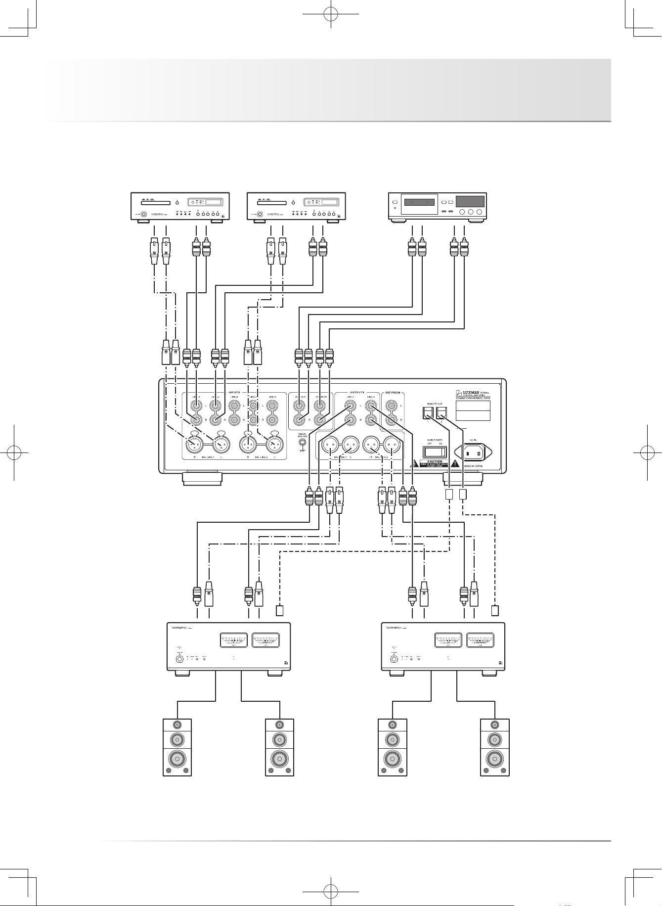
Connections
CD/SACD PLAYER
POWER AMP 2
SPEAKER SYSTEM 1
SPEAKER SYSTEM 2
CD/SACD PLAYER RECORDER
Normal stereo playback
L R
L R
L R
L R L R
L R
12
L R
POWER AMP 1
L R
L R
L R
L R
REMOTE REMOTE
L R

CONTROL AMPLIFIER C-700u
Before Connecting
Before connecting other devices, connect the jack side of the
accessory power cable to the AC inlet of this unit.
Before connection, turn off the main power switch of this
unit and the power of all other connected devices to prevent
unexpected accidents that may be caused by noise.
How to connect power supply
Use the accessory power cable and insert the AC plug in an
outlet on the wall in the room where the unit will be installed.
How to connect the input terminals to
input devices such as a CD player
Connect the output terminals of an input device such as a CD
player to the input terminals of this unit with pin-plug cables
or balanced cables.
In connecting, take great care not to connect the right and
left channels reversely. If these are connected reversely the
localization of sound images is deteriorated and proper play-
back is not acquired.
In case of using pin-plug cables, If the ground side of pin-plug
cable is floating, it may cause generation of noises like hum,
deterioration of S/N ratio. Be sure to insert the plug securely.
How to connect the output terminals to
output devices such as a power amplifier
Connect between the input terminals of an output device
such as a power amplifier and the output terminals of this unit
with pin-plug cables or balanced cables.
In connecting, take great care not to connect the right and
left channels reversely. If these are connected reversely the
localization of sound images is deteriorated and proper play-
back is not acquired.
In case of using pin-plug cables, If the ground side of pin-plug
cable is floating, it may cause generation of noises like hum,
deterioration of S/N ratio. Be sure to insert the plug securely.
How to connect the remote output
terminal to a power amplifier
Connect the remote input terminal of a power amplifier such
as Luxman M-700u to the remote output terminal of this unit
with the dedicated remote cable (no polarity) attached to the
power amplifier.
Through the connection, the power of the power amplifier can
be turned on and off by the operation switch of this unit.
Two (2) remote output terminals are available, and both ter-
minals provide the same signals. Use them according to your
taste.
Use the dedicated remote cable only for the connection be-
tween Luxman control amplifiers and Luxman power amplifi-
ers. Connection to such a terminal that the remote output of
this unit is short-circuited may cause a malfunction.
When this unit is connected to an output device, turn off the
main power switch of this unit or turn this unit to the standby
state to protect the amplifier and speakers from excessive
input, and turn off the power of the input/output devices con-
nected to this unit. After connection, confirm that connec-
tions are appropriately done and turn this unit and the input/
output devices to the operating state.
How to connect a recorder
Connect the input terminals of a recorder to the record output
terminals of this unit with pin-plug cables.
Through the connection, while listening to a sound source
selected by the input selector, it is possible to record the lis-
tening source at the same time. Next, connect the output
terminals of the recorder to the monitor input terminals of this
unit with pin-plug cables. Then, press the monitor switch of
this unit, it is possible to listen the recorded source and check
the recording condition at the same time.
In connecting, take great care not to connect the right and
left channels reversely. If these are connected reversely the
localization of sound images is deteriorated and proper play-
back is not acquired.
If the ground side of pin-plug cable is floating, it may cause
generation of noises like hum, deterioration of S/N ratio. Be
sure to insert the plug securely.
13

Connections
POWER AMP 1 POWER AMP 2
SPEAKER SYSTEM 1
SPEAKER SYSTEM 2
AV AMP/PRE AMP
External pre playback
L R
L R
REMOTE REMOTE
L R
L R
14
L R

CONTROL AMPLIFIER C-700u
External pre playback
Connection of external pre-input terminal
to input devices such as an AV amplifier
When this unit is used through the external pre-input, only the
unbalanced output terminal is valid as an output terminal of
this unit. There is no output at the balance output terminal.
When the main power switch is turned off or this unit is in the
standby state, external pre -input signals are always provided
from the unbalanced output terminal regardless of the exter-
nal pre switch setting.
Connect the pre-out terminal of an input device such as an
AV amplifier and a pre-amplifier to the external pre-input ter-
minal of this unit with a pin-plug cable.
In connecting, take great care not to connect the right and
left channels reversely. If these are connected reversely the
localization of sound images is deteriorated and proper play-
back is not acquired.
If the ground side of pin-plug cable is floating, it may cause
generation of noises like hum, deterioration of S/N ratio. Be
sure to insert the plug securely.
When the external pre switch is set to ON, the volume control
of this unit cannot adjust the sound volume.
It is necessary to adjust the volume at the input device’s side
(AV amplifier, pre-amplifier etc.) connected to the ext pre-in-
put terminal.
If a device that has no volume adjustment function such as
a CD player is connected to the external pre-input terminal,
the volume control of this unit cannot function, and there-
fore, sudden loud sound may be generated when the external
pre-input is selected, which may cause hearing loss or dam-
age to the speakers.
For such input devices, be sure to use a pre-amplifier or the
like equipped with the sound volume adjustment function.
After checking the sound through the speakers with volume
lowered, adjust the volume to your favorite level.
15

Operations
Before operation
1. Be sure that the connections are correctly performed.
(Normal playback cannot be achieved with wrong con-
nections of R and L.)
2. When the power is turned on or off or the input selector
is changed over, set the volume control to the minimum
position in advance.
Playback procedure
1. Press the operation switch to turn on the switch after
ensuring that the volume control is set to the minimum
position.
2. Select a playback source by the input selector.
3. Adjust the sound level by the volume control.
4. Operate the line straight switch, balance control, tone
control, and the like according to the playback source.
How to operate line straight switch
The line straight switch is used to play back with the short-
est signaling route for enhancing the purity of the source
selected with the input selector. When this switch is set to
ON, the tone control and loudness are bypassed.
How to operate balance control
The balance control is used to adjust the balance of sound
volume between right and left channels.
When the balance adjustment is not required, the balance
control is set to the center position.
How to operate the tone control
This unit has the tone control function for the low-frequency
and high-frequency ranges.
The low-frequency range type works in the 300 Hz or lower.
The tone control is set to flat frequency characteristic at the
center position. Rotating the control clockwise makes the
low–frequency range enhanced, and rotating the control
counterclockwise makes the low-frequency range attenu-
ated.
The high-frequency range type works in the 3 kHz or higher.
The tone control is set to flat frequency characteristic at the
center position. Rotating the control clockwise makes the
high–frequency range enhanced, and rotating the control
counterclockwise makes the high-frequency range attenu-
ated.
For both the low-frequency and high-frequency ranges, the
right and left channels interlockingly function.
When the line straight switch is set to ON, the tone control
does not function.
How to record a source
1. Select a source to be recorded with the input selector.
2. Activate the rec out by the preset function of the remote
control.
3. Play the source to be recorded and set the recorder to
the recording state.
* Operation of the tone control or balance control does not
affect the recording signals.
* Rec out functions when the power is turned on.
16

CONTROL AMPLIFIER C-700u
Memory
This unit memorizes the following items when the operation
switch is set to OFF or the main power switch is set to OFF:
Inhibition and caution
When a setting cannot be changed, an error message as fol-
lows is displayed:
Item Default
INPUT Selected source
OUTPUT MODE Selected mode
BAL PHASE INPUT-1, 2 : 3±, 2±
OUTPUT : 3±, 2±
BAL INVERT NORMAL / INVERT
DIMMER Normal light/dim/very dim/
light off
ZOOM ON / OFF
LOUDNESS ON / OFF
LINE-STRAIGHT ON / OFF
EXT PRE ON / OFF
MONITOR ON / OFF
REC OUT ON / OFF
Memory reset
The following operations restore all the settings to the factory
defaults.
Display Caution
UNBALANCE
MODE!!
STRAIGHT
ON!!
EXT PRE
MODE!!
EXT PRE
MODE!!
When the input and output are
both unbalance, the balanced
phase cannot be inverted.
When the line straight is set to
ON, loudness cannot be selected.
When the external pre is set to
ON, mute cannot be selected.
When the external pre is set to
ON, the output mode cannot be
changed.
(1) Turn this unit to the standby state.
(2) Hold down the operation switch on the main unit for 5
seconds or more and press the dimmer switch once while
holding down the operation switch.
That’s all for memory reset.
Factory default
Item Default
INPUT LINE-1
OUTPUT MODE UNBALANCE
BAL PHASE INPUT-1, 2 : 3+, 2−
OUTPUT : 3+, 2−
BAL INVERT NORMAL
DIMMER MAX (under normal conditions)
ZOOM OFF
LOUDNESS OFF
LINE-STRAIGHT OFF
EXT PRE OFF
MONITOR OFF
REC OUT ON
17

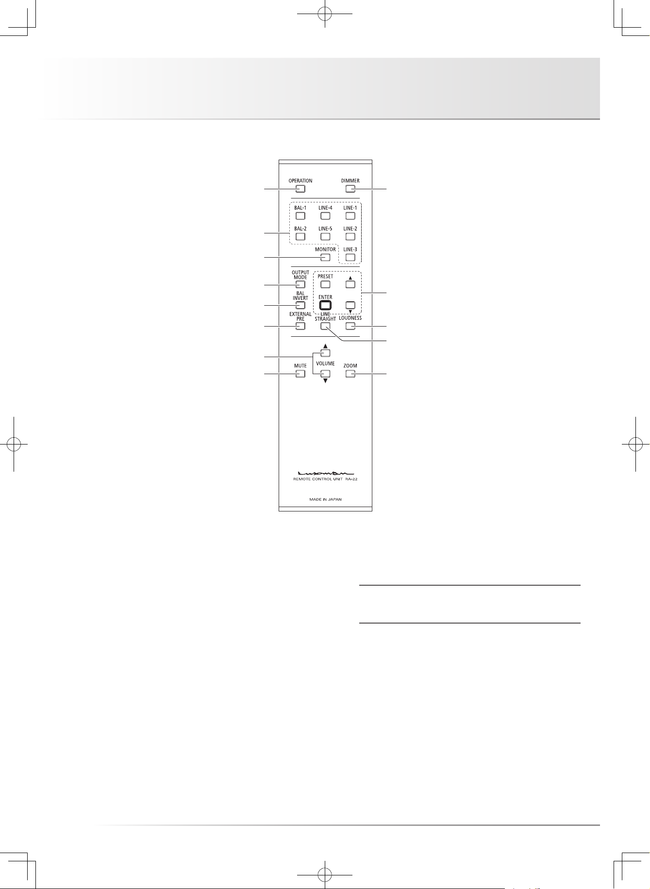
How to use Remote Control
1
2
3
5
6
8
7
10
11
13
4
12
Remote controller (RA-22)
9
1. Operation switch (OPERATION)
Turns this unit from the standby state to operation state.
When the main power switch on the rear panel is turned on
to set this unit to the standby state and this switch is turned
on, this unit is set to the operation state.
Pressing this switch again at the operating state turns the
unit to the standby state.
2. Input selector
(LINE-1, LINE-2, LINE-3, LINE-4, LINE-5,
BAL-1, BAL-2)
Selects the unbalanced input terminal or balanced input ter-
minal, both of which are located on the rear panel.
During input selecting operation, input/output muting circuit
is in operation and the unit will be on mute.
3. Monitor switch (MONITOR)
This switch is to activate the monitor input terminal.
ON: Plays back a source from the recorder.
OFF: Plays back a sound source selected by the input se-
lector.
By pressing this switch, the monitor switches from on to off.
18

CONTROL AMPLIFIER C-700u
4. Output mode selection switch
(OUTPUT MODE)
Selects an output mode from the following 3 kinds: unbal-
anced output, balanced output, and both (unbalanced +
balanced) output.
By pressing this switch, the output changes as follow:
→BAL→BOTH→UNBAL ...
UNBAL
• Unbalanced output (UNBAL)
Sound comes out from LINE-1 and LINE-2.
• Balanced output (BAL)
Sound comes out from BAL LINE-1 and BAL LINE-2.
• Both output (BOTH)
The unbalanced outputs, LINE-1 and LINE-2, and the
balanced outputs, BAL LINE-1 and BAL LINE-2, provide
audio output.
Factory default: Unbalanced output (UNBAL) mode
The input/output muting circuit is activated to mute sound
during selecting an output mode.
Every output mode can store preset values, respectively.
5. Balanced phase inversion switch
(BAL INVERT)
Inverts the balanced phase specified with the preset func-
tion of this unit. When the phases of a balanced input and a
balanced output must be inverted against the preset state,
press this switch to invert the balanced phases.
By pressing this switch, the balanced phase changes as
follows: NORMAL
During toggling the balanced phase between NORMAL and
INVERT, input/output muting circuit is in operation and the
unit will be on mute.
→INVERT→NORMAL→INVERT …
7. Volume control switch (VOLUME)
Adjust the output level of this unit.
Pressing these switches change the output level.
• Pressing
• Pressing
▲ increase the sound volume.
▼ decrease the sound volume.
8. Mute switch (MUTE)
Deadens the sound temporarily.
To cancel mute, press the mute switch again.
Volume level change adjusts the volume level while the
sound is muted but does not cancel the mute function.
9. Dimmer switch (DIMMER)
Adjusts the brightness of the input display and volume
display on the display window.
The brightness can be adjusted in 4 stages from no light to
normal lighting on.
By pressing this switch, the brightness changes as follows:
Normal light
Selection of no light displays “DISPLAY OFF” for 1 second
and the sign turns off.
Factory default: Normal light
→dim→very dim→light off→Normal light …
10. Preset switch (PRESET)
Enter switch (ENTER)
Determines adjustments or setting values.
▲ switch (UP)
▼ switch (DOWN)
Changes levels or settings.
6. External pre switch (EXTERNAL PRE)
Input selector switch to select the external pre-input termi-
nal (EXT PRE) on the rear panel
ON: Outputs sound signals connected to EXT Pre terminal
(pre-amplifier, AV amplifier etc.) directly.
OFF: Plays back a sound source selected by the input se-
lector.
Holding down the switch for approx. 1 second toggles the
external pre switch ON and OFF.
When the external pre switch is set to ON, the external pre
indicator lights up.
19

How to use Remote Control
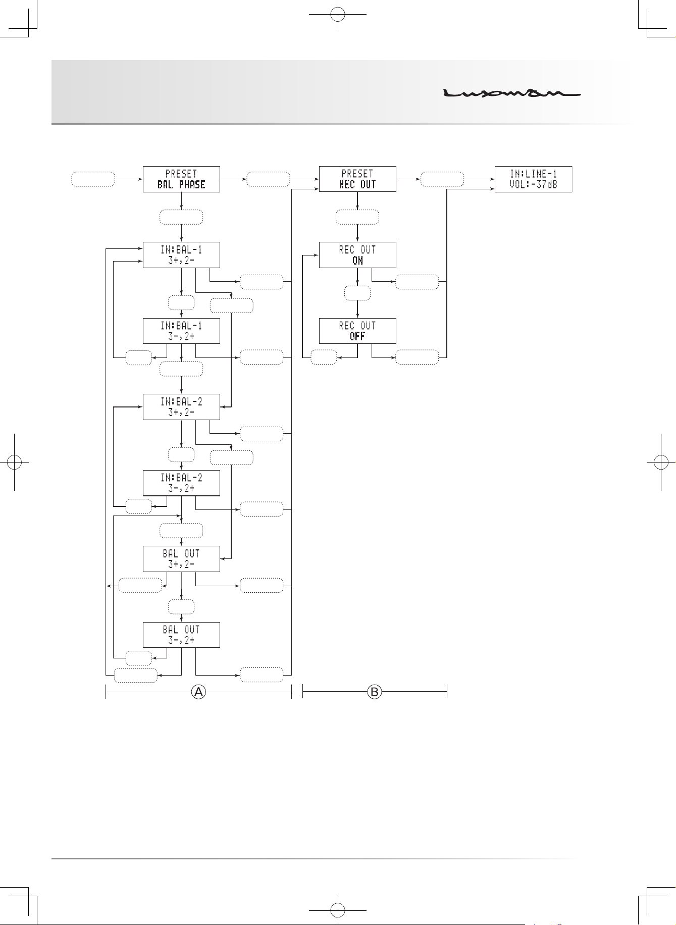
Balanced phase setting/BAL PHASE
presetting
The balanced phase can be set for input and output, re-
spectively.
(1) Press the PRESET switch to turn this unit to the preset
mode, and BAL PHASE blinks. (1st line of A) If the bal-
anced phase is not adjusted, press the PRESET switch
to go to the next REC OUT setting.
(2) Press the ENTER switch, 3+ and 2- of BAL-1 blink to
show that the BAL LINE-1 phase inversion setting of
the balanced input can be performed. (2nd line of A) If
the ENTER switch is pressed one more time, the step
goes to the BAL LINE-2 phase inversion setting of the
balanced input.
(3) Press
▲ or ▼ to invert the BAL LINE-1 phase of the
balanced input and the display turns to 3- and 2+. (3rd
line of (A)) Press
back to 3+ and 2-.
▲ or ▼ again to turn the phase setting
(8) Press the ENTER switch to set the step back to the
step (2) to enable the BAL LINE-1 phase inversion set-
ting of the balanced input again.
If the PRESET switch is pressed, the step goes to the
next REC OUT setting.
If the PRESET switch is pressed in any state of the
steps from (1) through (8), the setting is memorized,
BAL PHASE ends, and the step goes to the next REC
OUT setting.
If no entry is performed for 1 minute in the preset mode,
the current mode ends with the immediately preceding
setting stored, and the regular display resumes.
Record output terminal on and off
setting/REC OUT presetting
Providing the record output terminals with audio signals can
be toggled on and off.
To record sound using a recorder, set this setting to ON.
To enjoy playing back the music high in purity, set this set-
ting to OFF.
(4) Press the ENTER switch to determine the changed set-
ting of BAL LINE-1, 3+ and 2- of BAL-2 blink to show
that the BAL LINE-2 phase inversion setting of the balanced input can be performed. (4th line of A) If the EN-
TER switch is pressed one more time, the step goes to
the BAL OUT phase inversion setting.
(5) Press
(6) Press the ENTER switch to determine the changed
(7) Press
▲ or ▼ invert the BAL LINE-2 phase of the bal-
anced input, and the display turns to 3- and 2+. (5th
line of A) Press
back to 3+ and 2-.
setting, 3+ and 2- of BAL OUT blink to show that the
BAL LINE-1 and BAL LINE-2 phase inversion settings
of the balanced output can be performed. (6th line of
A) Press the ENTER switch to set the step back to
the step (2) to enable the BAL LINE-1 phase inversion
setting of the balanced input again.
▲ or ▼ again to turn the phase setting
▲ or ▼ to invert the BAL LINE-1 and BAL LINE-2
phases of the balanced output and the display turns to
3- and 2+. (7th line of A) Press
the phase setting back to 3+ and 2-.
▲ or ▼ again to turn
(1) Press the PRESET switch twice. The 1st line of B ap-
pears and the preset mode is activated.
“REC OUT” blinks. If the on-off setting is performed,
press the ENTER switch. If the on-off setting is not per-
formed, press the PRESET switch to exit from the pre-
set mode.
(2) When the ENTER switch is pressed, the currently se-
lected ON (or OFF) blinks to show that REC OUT ON or
OFF can be selected. (2nd line of B)
(3) Press
Press the PRESET switch to exit from the preset mode.
Even if the ENTER switch is pressed in this state, the
Pressing the PRESET switch allows the setting to be
If no entry is performed for 1 minute in the preset mode,
▲ or ▼ changes the setting to OFF (or ON). (3rd
line of (B)) Pressing
to ON (or OFF).
ENTER switch does not function.
memorized in any state of the steps from (1) through (3)
and the preset mode to end.
the current mode ends with the immediately preceding
setting stored, and the regular display resumes.
▲ or ▼ again turns the setting back
20
CONTROL AMPLIFIER C-700u
PRESET
PRESETPRESET
ENTER ENTER
▲,▼
▲,▼
▲,▼
ENTER
▲,▼
ENTER
ENTER
ENTER
PRESET
PRESET
PRESET
PRESET
▲,▼
PRESET
▲,▼
PRESET
ENTER
▲,▼
ENTER
PRESET
▲,▼
PRESET
21
How to use Remote Control
1
2
3
5
6
8
7
10
11
13
4
12
Remote controller (RA-22)
9
11. Loudness switch (LOUDNESS)
Psychoacoustically compensates the frequency character-
istics when the volume control is set to -16 dB or less.
This compensation allows listeners to complement human
listening characteristics when the sound volume is in the
low level.
By pressing this switch, the loudness setting toggles be-
tween ON and OFF repeatedly.
The loudness indicator lights up when the loudness switch
is on.
When the line straight switch is set to ON, this switch does
not function.
12. Line straight switch (LINE STRAIGHT)
This switch is used to increase the purity of the sound qual-
ity by bypassing (skipping) the tone control circuit.
By pressing this switch, the line straight setting toggles be-
tween ON and OFF repeatedly.
The line straight indicator lights up when the line straight
switch is set to ON.
When the line straight switch is set to ON, the tone control
and loudness do not function.
13. Zoom switch (ZOOM)
Enlarges the current volume level and displays it.
When this switch is pressed again, the regular display re-
sumes.
22
CONTROL AMPLIFIER C-700u
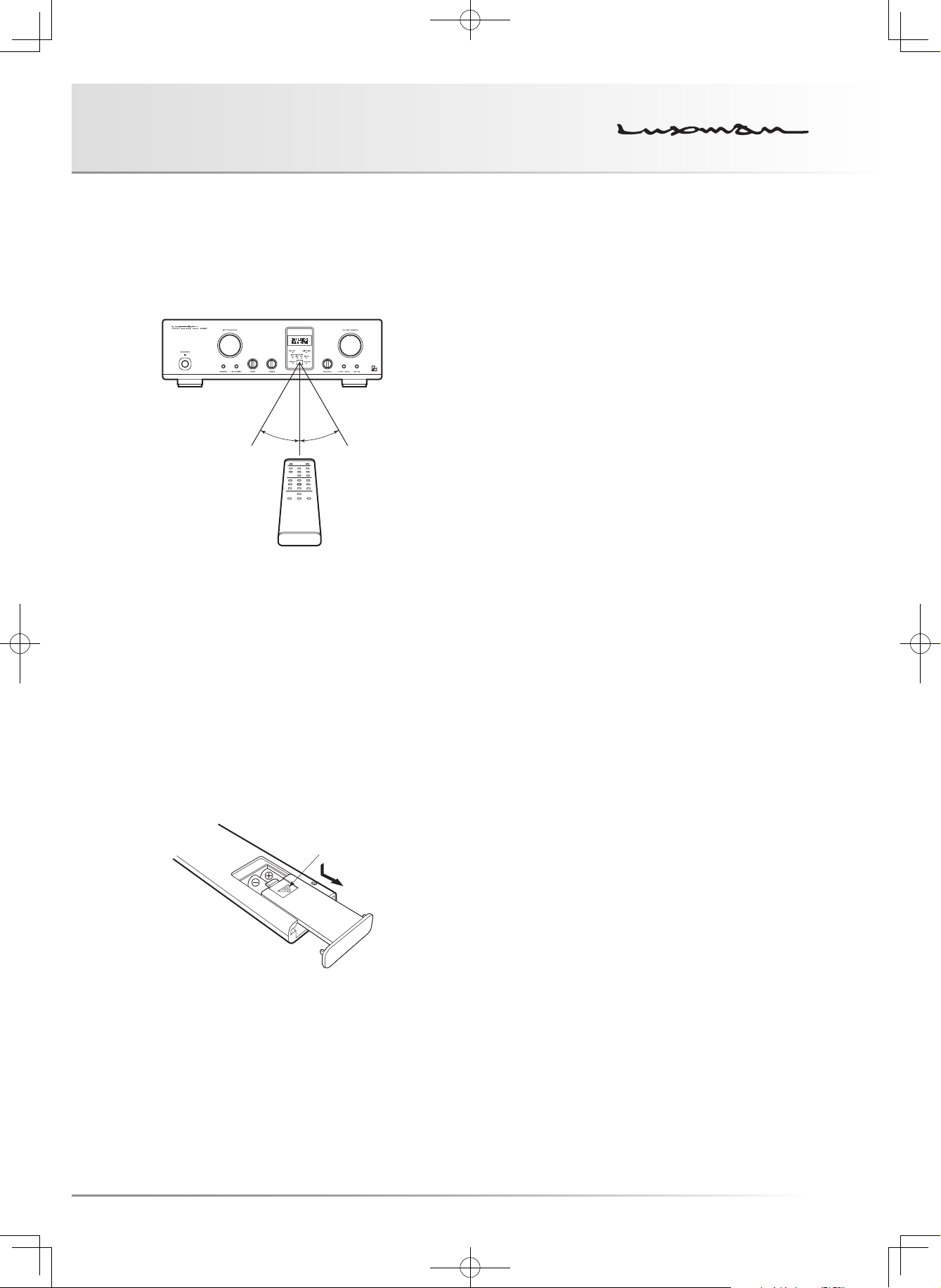
Remote control
Effective distance: approx. 5 m
The remote control shall be aimed at the remote sensor of
this unit within the specified angle range shown in the illus-
tration when used.
30°30°
Dry cell
[How to load dry cells]
1. Remove the battery cover on the rear of the remote control.
Put your finger on the battery cover claw and slide the cover
downward to remove the cover.
2. Put 2 AAA batteries in the battery case as shown in the illus-
tration on the battery case in consideration of the polarity (⊕
and ⊖).
3. In the reverse order of battery cover removal, put the battery
cover back to the opening of the remote control and slide the
cover upward until it clicks.
Claw
* When the batteries start to lose power, the effective dis-
tance becomes shorter or the unit does not function even
though the switch is pressed.
In such a case, both of the batteries shall be replaced with
new ones at the same time.
* If the remote control is not used for a long time, the batter-
ies shall be removed from the case.
23

Block Diagram
L
MONITOR LMONITOR RREC OUT LREC OUT
B
B
B
B
INPUT SELECTOR
R
L
EXT PRE IN
LINE-1 L
LINE-2 L
EXT PRE
LINE
EXT PRE IN
LINE-1 R
LINE-2 R
EXT PRE
LINE
BAL-1 L
12
3
PHASE INVERT
L–
BAL-2 L
12
3
L+
R–
R+
BAL-2 R
BAL-1 R
12
12
3
3
BALANCE
BAL
→
UNBAL
REG.
ODNF-1
REG.
ODNF-2
REG.
POWER SUPPLY
STRAIGHT
LECUA-1 LECUA-2
MONITOR
L
TONE
CONTROL
L
LECUA-1 LECUA-2
R
STRAIGHT
R
INE-1 LLINE-1 RLINE-2 LLINE-2 RLINE-3 LLINE-3 RLINE-4 LLINE-4 RLINE-5 LLINE-5 R
UNBAL
→
XLR IN
TONE
CONTROL
BAL
PHASE INVERT
L+R+L–
12
3
INPUT SELECTOR
R–
12
3
12
12
3
3
R
AL-1 L
AL-1 R
AL-2 L
AL-2 R
24

CONTROL AMPLIFIER C-700u
F
TO OUTPU
T
–B2
AMP
DIFFRENTIAL
+B1
REG.
–3dB
–33dB
–4dB
–44dB
–B3
ODNF
–5dB
–55dB
MUTE
INPUT
SWITCH
SEMICONDUCTOR
0dB
–2dB
SEMICONDUCTOR
SEMICONDUCTOR
SWITCH
SWITCH
0dB
–1dB
–11dB
–22dB
1dB STEP
ATTENUATOR
11dB STEP
ATTENUATOR
EACH CHANNEL
+B3
–6dB
–66dB
–B1
–7dB
–77dB
–8dB
–9dB
–10dB
ATTENUATOR
CONSTRUCTION
CONTROL
ATTENUATOR
LECUA1000 (ATTENUATOR + AMP) /
ROM INPUT
25
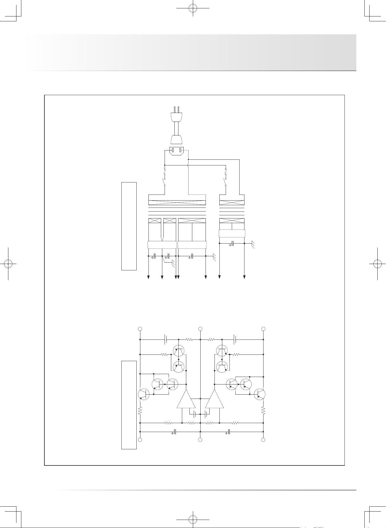
Block Diagram
POWER SUPPLY
POWER SUPPLY
RECTIFIER RECTIFIER
FOR AUDIO
FROM
POWER SUPPLY
RECTIFIER
FOR ACCESSORIES
–
+
FOR MICROCOMPUTER
FROM
–
+
26
REGULATOR FOR AMP
+B
ND GND
–B

CONTROL AMPLIFIER C-700u
Specifications
Input sensitivity LINE : 250 mV / 1 V output, 1 kHz, load 50 kΩ
BAL LINE : 250 mV / 1 V output, 1 kHz, load 100 kΩ
LINE → BAL LINE : 250 mV / 1 V output, 1 kHz, load 100 kΩ
BAL LINE → LINE : 250 mV / 1 V output, 1 kHz, load 50 kΩ
Maximum output LINE : 11 V / distortion 0.1 %, 1 kHz, load 50 kΩ
BAL LINE : 11.5 V / distortion 0.1 %, 1 kHz, load 100 kΩ
LINE → BAL LINE : 11.5 V / distortion 0.1 %, 1 kHz, load 100 kΩ
BAL LINE → LINE : 11 V / distortion 0.1 %, 1 kHz, load 50 kΩ
Input impedance LINE : 46 kΩ / 1 kHz
BAL LINE : 67 kΩ / 1 kHz
Unselected LINE : 33 kΩ / 1 kHz
Unselected BAL LINE : 67 kΩ / 1 kHz
Output impedance LINE : 90 Ω / 1 kHz
BAL LINE : 600 Ω / 1 kHz
Total harmonic distortion LINE : 0.007 % / 1 V output, 20 Hz - 20 kHz, load 50 kΩ
BAL LINE : 0.010 % / 1 V output, 20 Hz - 20 kHz, load 100 kΩ
LINE → BAL LINE : 0.007 % / 1 V output, 20 Hz - 20 kHz, load 100 kΩ
BAL LINE → LINE : 0.009 % / 1 V output, 20 Hz - 20 kHz, load 50 kΩ
Frequency response LINE : +0, −0.1 dB / 1 V output, 20 Hz - 20 kHz, load 50 kΩ
: +0, −3.0 dB / 1 V output, 5 Hz - 120 kHz, load 50 kΩ
BAL LINE : +0, −0.2 dB / 1 V output, 20 Hz - 20 kHz, load 100 kΩ
: +0, −3.0 dB / 1 V output, 5 Hz - 80 kHz, load 100 kΩ
LINE → BAL LINE : +0, −0.2 dB / 1 V output, 20 Hz - 20 kHz, load 100 kΩ
: +0, −3.0 dB / 1 V output, 5 Hz - 110 kHz, load 100 kΩ
BAL LINE → LINE : +0, −0.2 dB / 1 V output, 20 Hz - 20 kHz, load 50 kΩ
: +0, −3.0 dB / 1 V output, 5 Hz - 85 kHz, load 50 kΩ
S/N ratio LINE : 125 dB (IHF-A) / distortion 0.1 %,1kHz, load 50 kΩ
BAL LINE : 122 dB (IHF-A) / distortion 0.1 %,1kHz, load 100 kΩ (ATT. −87dB)
LINE → BAL LINE : 122 dB (IHF-A) / distortion 0.1 %,1kHz, load 100 kΩ
BAL LINE → LINE : 125 dB (IHF-A) / distortion 0.1 %,1kHz, load 50 kΩ (ATT. −87dB)
Tone control Max. amount BASS : ±8 dB at 100 Hz
of change TREBLE : ±8 dB at 10 kHz
Loudness control 100 Hz : +7 dB
10 kHz : +5 dB
Accessories • Power cable • Remote control, RA-22
• 2 pieces of “AAA” batteries • Owner’s manual
• Safety cautions
Power consumption 28 W
2 W (at standby)
Power supply 230 V ~ (50 Hz)
Max. external dimensions 440 (W) × 130 (H) × 430 (D) mm
Weight 14.6 kg (main unit only)
* Specifications and appearance are subject to change without notice.
27

Before Asking for Repair Services
While the unit is used, an unusual phenomenon may be confused as a malfunction for a certain reason. Prior to asking us for repair
services, please check the table below and read the instruction manual for the subsidiary devices. If the cause of the malfunction can-
not be identified, please contact your dealer. When we have once accepted your request for repair services, inspection fees and travel-
ing expenses may be claimed even though the unit is found to be normal.
Problem Cause Solution
No power is supplied even
though the main power switch
is pressed.
The standby indicator does not
light.
The operation indicator does
not light even though the operation switch is pressed.
No sound is generated. · The volume control or attenuator of the
· The power plug is disconnected from the
wall outlet, or it is not completely inserted.
· The power plug is disconnected from the
AC inlet, or it is not inserted completely.
· The main power switch is turned off. · Turn on the main power switch to light the
power amplifier is set to the minimum level.
· The input selector is not set to the source to
played back.
· The connected output terminal does not
match the selected output mode setting.
· Cable connections are incomplete. · Make cable connections securely.
· The mute switch of the remote control is
set to ON.
· Insert the power plug in the wall outlet completely.
· Securely insert the power plug in the AC
inlet.
standby indicator.
· Rotate the volume control or attenuator of
the power amplifier to adjust the sound volume.
· Set the input selector to the source to
played back.
· Adjust the output mode of the connected
output terminal according to the selected
output mode.
· Set the mute switch to OFF.
Sound is generated but the
sound volume is low.
The sound volume is low only at
one side channel.
Humming sound (boon or zzz
noise) is generated.
There is no effect of tone control.
28
· The external pre switch is set to ON. · Set the external pre switch to OFF.
· The balance control is rotated in a one-sided manner.
· The attenuator of the power amplifier is set
to ON.
· The grounding side of the connection cable
has no contact with the terminal.
· Induction noise is picked up from the power
transformer of another device.
· The input/output cables and speaker cables
are too close to the power cable.
· The line straight switch is set to ON. · Set the line straight switch to OFF.
· The balance control shall be set to the center position under normal conditions.
· Set the attenuator to OFF.
· Make cable connections securely.
· Install it distant from other devices. Use a
wall socket of a different line.
· Keep the input/output cables and speaker
cables away from the power cable..

CONTROL AMPLIFIER C-700u
Problem Cause Solution
The loudness function does not
work.
The external pre switch does
not work.
· The line straight switch is set to ON. · Set the line straight switch to OFF.
· To prevent malfunction, holding down for
approximately 1 second shall be required
for switching between ON and OFF in the
specifications.
· Hold down the external pre switch for approx. 1 second.
29

LUXMAN CORPORATION, JAPAN
AG00987E34A
Printed in China
 Loading...