

ULTIMATE
HIGH
FIDELITY
STEREO
COMPONENT
[l[]]OOOO[)G[jO
SERVICE
CL35 /m
CONTROL CENTER
MANUAL
CIRCUIT
'.
DESCRIPTION
non ieverted
in put
1/2
1/2
12AX7
ECC83
1/2
12AX7
ECC83
12AU7
ECC82
200V
2«JV
which
A-2
NFis14dB.
side.
special
has
+39dB
Local
2",H
fig. -1
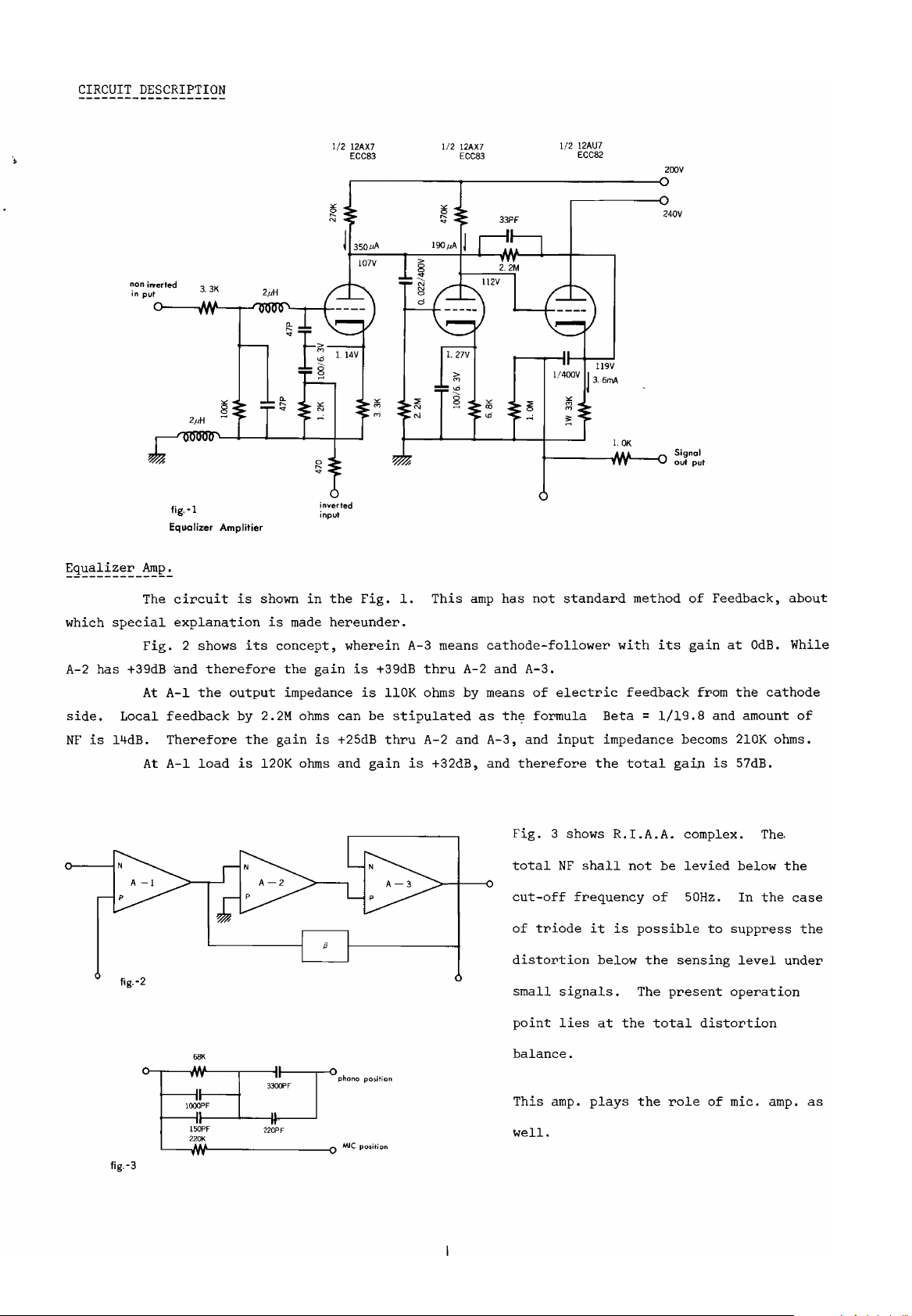
Equalizer Amplitier
The
circuit
explanation
Fig.
2 shows
and
At
A-I
feedback
Therefore
A-I
At
is
therefore
the
output
by 2.2M
load
is
shown
its
the
in
is
made
concept,
the
gain
impedance
ohms
gain
is
120K ohms and
inverted
input
the
Fig.
hereunder.
wherein
is
is
can
+25dB
1.
This
amp
A-3 means
+39dB
be
gain
thru
110K ohms by means
stipulated
thru
is
A-2 and A-3.
as
and
A-2
+32dB, and
t------;jw~~::l
has
not
cathode-follower
th~
A-3, and
Fig.
standard
of
electric
formula
input
therefore
3 shows
l.OK
method
with
feedback
total
Beta=1/19.8
impedance
the
R.I.A.A.
Signal
out
put
of
Feedback,
its
gain
from
and amount
becoms
gaLnis57dB.
complex.
about
at
OdB.
cathode
ohms.
The.
While
of
the
210K
flg.-2
fig.-3
total
NF
shall
cut-off
of
triode
frequency
distortion
~
,.
..
\~PF
II II
l;~F
2201<
."
330lPF
rr
220PF
II
..
position
position
~
phono
MlC
small
point
balance.
This
amp.
well.
signals.
lies
it
below
at
plays
is
the
not
be
of
possible
the
sensing
The
present
total
the
role
levied
50Hz.
to
distortion
of
below
In
suppress
level
operation
mic.
the
amp.
the
case
under
the
as
non
input
inveried
in~ut·
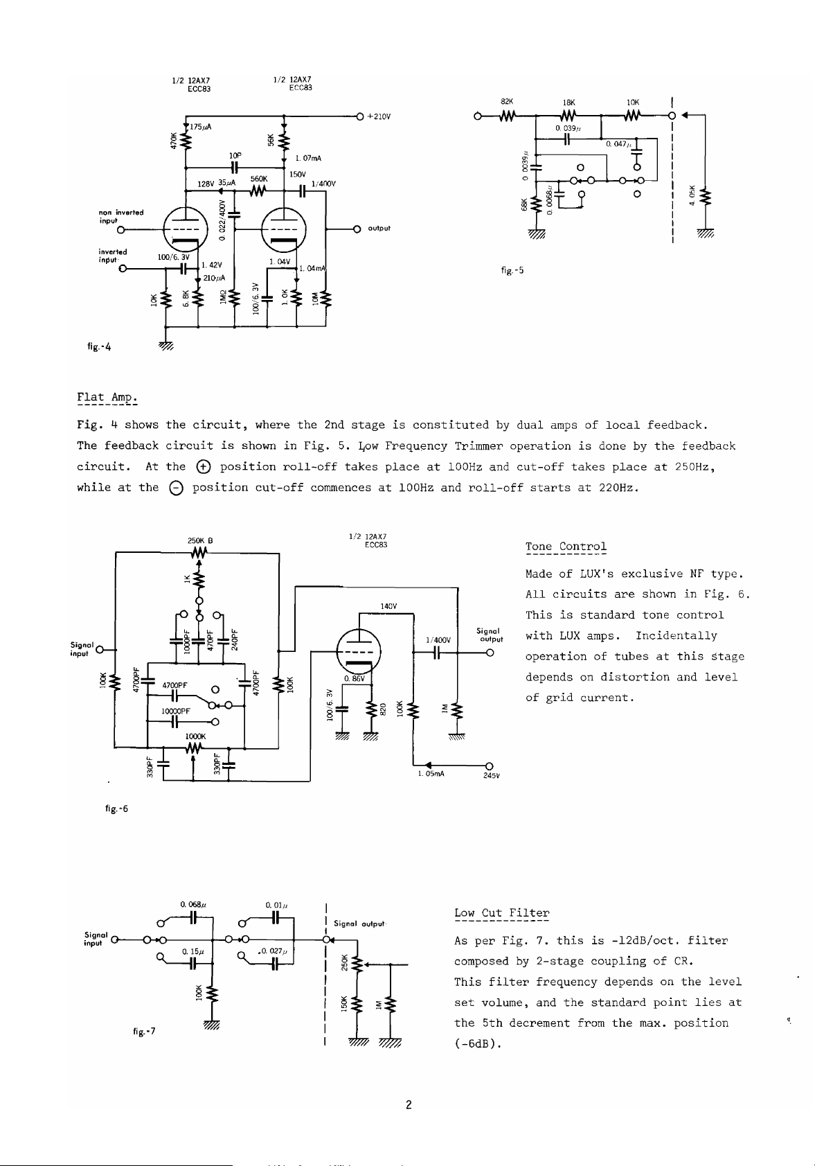
fig.-4
Fig.
The
feedback
circuit.
while
inverted
0-----11-
o--~r-1IH
4 shows
At
at
the
1/2
12AX7
ECC83
.--------_------Cl
the
circuit,
circuit
the
()
G)
position
is
position
where
shown
cut-off
1/2
12AX7
ECC83
in
roll-off
1/400V
the
2nd
Fig.
commences
5.
takes
stage
~ow
+21OV
output
is
Frequency
place
at
constituted
at
100Hz
Trimmer
100Hz
and
by
and
roll-off
82K
fig.-5
dual
operation
cut-off
starts
amps
18K
takes
of
is
at
10K
local
donebythe
220Hz.
place
feedback.
feedback
at
250Hz,
Signol
input
1/2
12AX7
25lJ<.
B
10001<
fig.-6
fig.-]
~271'
ECC83
Signnl ovtp'ut
140V
Signal
1/400V
'"
§
l.
05mA
output
~
~
245V
Low
Cut
As
per
composed by
This
set
volume,
the
5th
(-6dB)
Tone
MadeofLUX's
All
This
with
operation
depends
of
Filter
Fig.
filter
decrement
.
Control
circuits
is
LUX
grid
7.
this
2-stage
frequency
and
the
standard
amps.
of
on
current.
is
coupling
standard
from
exclusive
are
shown
tone
Incidentally
tubes
distortion
-12dB/oct.
depends
the
max.
at
of
point
control
this
and
CR.
on
the
position
NF
in
filter
lies
Fig.
level
type.
stage
level
6.
at
"
2
?45V
"
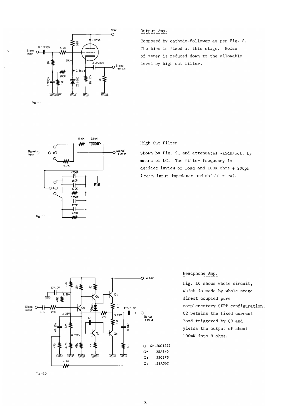
fig.-S
Signa~
o----c)-.M)-----f--------1I------<O
input
5.6K
4.7K
4700P
Signal
'Jutp.Jl
92rnH
S~~~pa~t
~':!!2'!!_~~2.:.
Composed by
The
bias
of
zener
level
~~~~-g,!!_~~~!~::
Shown by
means
decided
(main
by
of
input
cathode-follower
fixed
is
reduced
is
high
cut
Fig.
9,
LC.
The
inview
impedance
of
at
filter.
and
filter
load
this
down
attenuates
and
and
as
stage.
to
the
frequency
lOOK
shield
per
Fig.
Noise
aliowable
-12dB/oct.
is
ohms
wire).
8.
+ 200pF
by
270P
1.2K
470K
fig.-9
~~g~:l
0--II-.Mf'-~-+___I(
p
2.2/22K
t---t--N'I--+-:-::C::c-1--lII---r--G
6.52V
Signol
output
Ql
Q3;2SC1222
Q2
;2SAMO
Q4 ; 25C375
Q5 ;2SA562
Fig.
10
shows whole
which
is
made
direct
coupled
complementary
Q2
retains
load
yields
100rnW
triggered
the
into
by
pure
SEPP
the
fixed
byQ3and
output
8 ohms.
circuit,
whole
stage
configuration.
current
of
about
fig.-lD
3

input
" 1
6.52V
rms
fig.-ll
r---~--O+6.
lN4002
IN4002
0
~
~
52V
The
circuit
Q212
given
supply
(CR
Q211
terminal
Q2l2
to
is
put
on
is
=400uF.Kohms).
is
activated
is
turned
let
the
Thenafter
PB-667
is
shown by
into
the
base
100%
0.4V
to
be
open
off
relay.contact
the
base
operation
through
equals
when
Q213
from
the
current
Fig.
short-circuiting.
instant
make
11.
the
instant
R231
and
6%.
To
is
turned
the
and
of
Q2l3issupplied
Power
supply
the
power
on,
To
6%,
and
C215.
charge
power
is
switched
short-circuited.
section
is
activate
T/CR
relay
by
switched
is
functions
off,
D204.
is
it
some 0.4V
needed
and
commontoheadphone
on.
As
by
6%
to
break
then
to
is
needed.
which
Q2l3
Q213
bias
corresponds
allowing
and
Q2l1
amp
When
the
are
is
and
the
Pre
pilot
gradually
power
to
24
sec.
Out
turned
lamp.
off
"
4

~g~§~--~~~~~~---~§~~~~~~~~!_~~~!~-~!~!
PB-667
Description
Printed
1.
2. Diode
3.
4.
5.
Varister
6.
Transistor
7.
8.
9.
10.
11.
Electrolytic
12.
13.
14.
IS.
Tantalum
16.
Polyester
17.
Ceramic
18.
Resistor
19.
20
21
22
en
23
24
25
26
27
28
29
30
31
32
33
34
35
36
37
38
Relay
39
Circuit
"
"
"
Board
"
"
I!
I!
I!
I!
Film
I!
I!
I
I!
I!
"
"
"
I!
"
"
"
TYPE
PB-667
SD-lB 4
lN4002
M4E
lK188
VD-1221
2SA562Y
2SA640
2SC735Y
2SC1222E
25V
10V
6.3V 470uF
10V
lOY
SOV
SOV
10K
2.2K
lK
270K
1M;2
68K
47K
27K
22K
15K
12K
10K
3.3K
2.7K
1.
2K
680
470
100
47
8.2
1
6V2circuit
4.7uF
47
330uF M
2.2uF
0.047uF
47pF
~S%
11
"
"
"
I!
"
" "
"
"
"
"
I!
"
"
"
"
" "
" "
"
"
uF
(NON
lW
I!
I!
1/2W
1/4W
I!
"
"
I!
"
'1
"
I!
"
"
"
"
"
transfer(AE1322}
POLAR)
PB-668/'669
----------
Resistor
QUANTITY
1
3
2
1
2
3
2
2
6
1
4
2
1
2
3
2
2
1
1
1
1
2
2
2
2
2
2
3
1
2
2
2
2
1
4
2
5
1
1
2
3
4
5
6
7
8
9
10
11
12
13
14
15
16
17
18
19
20
21
22
.
23
24
25
26
27
28
29
30
31
32
33
34
35
36
37
38
39
40
41
42
Metalised
Polyester
Styrol
43
44
Ceramic
45
46
47
Zener Diode
48
Electrolytic
49
Coil
SO
51
Printed
52
"
"
"
I!
"
I!
"
"
I!
"
"
"
"
II
"
"
"
"
"
"
"
"
"
"
I!
"
I!
I!
"
I!
I!
I!
I!
I!
I!
"
"
"
I!
I!
I!
I!
"
Circuit
Film
Film
Board
,Ai

11NPUT IMPEDANCE
SELECTOR
PHONO·2
r------------------r-,
I I I
I
INPUT SELECTOR
A
B
B
A
...,-----.....:;,
BASS FREQUENCY
PHONO·1
MIC.
-J
MIC.
J.ACK
AUX·3
AUX·2
AUX·'
rr:::::
~~~
,
I ,
I
~~
'I
.Thisdiagramisfor
• Power source section
the
LEFT
omitted.
CHANNEL.
R.CH.
OUTPUT
LEVEL
L.CH.
~N'CONNECTOR
R.CH•
SET
~
CATHODE
FOLLOWER

SPECIFICATIONS
Tubes:
Frequency
T.H.O.:
Output
Output
I
nput
(output;1V,
output
Input Impedance:
SIN Ratio:
Equalizer:
Tone Control:
Filter:
Low Frequency
Attenuator:
Accessories:
Dimensions:
Weight:
Response:
Voltage:
Impedance:
Sensitivity:
level max.)
Trimmer:
Bass:
Treble:
12AX7 (6),
15Hz-40,OOOHz
no more than 0.06% (rated
Max. 15V (distortion 0.3%)
550-ohms
phono-1
phono-2
aux-l 140mV (variable)
aux-2 140mV
aux-3 140mV (variable)
microphone
phono~
phone-2 50K ohms
aux-l lOOK ohms
aux-2 150K ohms
aux-3 lOOK ohms
microphone 50K ohms
better than 64dB (phono-l & 2)
better than 77dB (aux-l & 2 & 3)
better than 60dB (microphone)
R.I.A.A. (strandard deviation ± 0.3%)
LU
X type NF system
150Hz, 300Hz, 600Hz
1.5KHz, 3KHz,
Low cut 25Hz, 60Hz
High cut 7KHz, 12KHz
100Hz - 800Hz
-20dB
Tape
Impedance Selector, Socket
transformer, Headphone
476
(7-3/5")Hmm
Net 12Kgs (26.40
Gross
1 lOOK ohms, 50K ohms, 30K ohms
Monitor
(19-1/25")W
14Kgs (30.8
12AU7
l.4m
l.4mV
0.7mV
(1)
V
6KHz
(±
Circuit, Phono Input
x
Ibs)
(-ldB)
with
defeat position
0.8dB, 250Hz)
Ci
275(11")0
Ibs)
output:
for
rcu
it
step-up
x 190
2V)
Specifications and appearance design subjecttopossible
without
notice.
8
change

LUX CORPORATION, JAPAN
HEAD OFFICE81FACTORY
1-8-31 NAGAHASHI, NISHINARI-KU OSAKA
PHONE:632 0031 CABlE:lUXELECT OSAKA
TElEX:J63694
LUX
200
PHONE:
AUDIO
Aerial
(516)
Way.
822-7070
OF AMERICA
Syosset.
New
York
11791.
LTD.
U.S.A.
PrintedinJapan
~.

AlII
...
....
AIII·n
AUI-l
I
Ih
1,,,Ola
·n
·1
,••12A11
Ii
MIC.
MIC.
lEe.
lB.
JACI
liT·I
IIT-l
PIE
OUT
b.JI~l(
II)
Imln
2
J
r---+-IINV~~fV'\r--+~~V\r--.--------~1l>
lul_n(II)
I.
1m 2.210(11)
.........
VV'w---t~--~.t~
1m 11!l(II)
IIlIIXn(II)
"-"''VV''--1II~11l>
8J>
.-
.J'IY
·2.
•
24ft
•
,.
..
IT.·I
lie.
lie.
AlII·I
AIII·n
...
...
AUI·!
JACI
-1
·n
I
I
I
I
I
I
I
I
I
I
I
L_
---
-
----
------
StleHI$
S
11.
1'.
S
21.
S
31.
S
41.
S
51.
SI
S
11.
SII.
S
91, 9b.
S
lOa.
S
11a.
S
121.
S
13a.
S
14
2'.
3'.
D.
D
lb
lb.
lab
11b
12b.
13b.
2e.
3e.
4c.
Ie
ge.
2.
:N.
~
...
12c.
13e.
9'
I
CHAIIln
,..
S.
31.31SeIIcbI
...
....
MtIIII
A
....
lJ.
T.
Tn
Tn
low
12.
13d
HiP
Pow.
I.
Up
Tr.
J_
"fill
h.
0CIt
CIt
IIIP.
-r-------------
(1.
100102.SOlo3.3310)
(.1.
8ft
2.
11-)
(1.
AUIm2.
•.
AUIn5.
(1.
,.
(1.
MOIitar1.2.
(1.
leverse2.loi3.I
4.
".·1
(1
.•
t
(1.1M2.
(1.
DefIat
(1.
158Hz2.300Hz
(1.
1.5IHz,2.31Hz3.&IHz)
O.
60Hz2.Detut
(1.
11Hz
22.SOIfse
5.
".·L)
2.
II)
Fl.
3.
2.
II)
2.
Iefut
PIIOIo
AUII5.
SDIlrse3.MOIIIr
Up)
3.
n 3.'.I
ME)
3.2101)
+l
3.
600Hz)
25Hz)
3.
121Hz)
:
-133.
-1110
--t
I
1201
-1226
~,
%W
I
I
I
I
I
I
I
I
-t-
'I
'Ila.
lb
'I
2a.
2b
VI
3a.
3'
'I
.a.•,
VI
Sa.
5b
,.
6a.
2)
VIla.
VI
6'
l'
la.
Ib
AUImLevel
AUIILevel
I
...
Mlil
lass
TreIIII
Lev.
Had,..
'011.
Sit
Sit
Level
Set
....
11
1101
I
I
I
I
I
i
_.J
CL35111
I

lUX-III
PHONO-
II
PHONO-
lUX-II
lUX-I
::
JI"
~
v.
__
",
'I,.
I
~
tI
~
~
25"""A,
SI.
VI,.Z5IIll(A)
~fC-
« I
'~~V-::"'1oJ:<>11f-++I--"'-II-'-'IN1-ID--+-IJ
~_~+++-
.-0-.
2
I::
W
1
+---t--------.
S"),2I".110
~I
l,mD
__
----Jl--
2
rS2C
~
I
~~
~1
~
S..11151.IID"
5Jr
_iff h
1111
IIID
II
l.~..........
__
Cll_,_11511f-JINV'
...
.rnrr
__
'~"""'-'-"T.J..~-
..
-~
1111
~
!;',.J2Axl
_~-
107VV
\
_/
miD
I11IZ.211
Ill'
~I~I;,;._
~!~
-+--""---J~-+
E,
clIl'isM
L _I'"
--u..
!lt-+_51J'.- I IIl1.ul l'llHOD" .
.
I
~I"
'_
~'~
~
".12Ax1 ,
I1V
~:~·~ ~
__
I
2 t
'~_g
·1,1
A<
~14
..
1ZAIlI
A,
k§- ;
~
+-+--..-...,
'_
:;
+--+""""-+_--I~-+-_-t-
!
C,
1.~lu~1
1 I
r-'~
,."2AxlI1l156DID".12Axl
~I
LI,'r.
1.'.1:"
~
S..
lor
Al
'111;""
I," lliD IHII2lD .
;~~
~lzn
~;tl'l
_"
!!~'_~
~
'm
;
........~........-+.......
SI,
te'
Y
J"~lil
\./
'v
"
;,;._'lfI
."
f1
I~
.;~II.u1
21
II
Al
ICV'·',-,Z::"'--{W.V'---t--,---t
.:;
~
~
~
~
~
_--+
s..
'~
I
III11D
2
1
ct
!!!.:;
.!l
H
........
So,
~
,~J
i I
...,+...;~
?JI
r.:
VI••25OIll(1)
• 3
I
~
C,lllpI
"~'ll
Cll
11
1Pr,;""--;t1.'·-
•••
~;~
21'!-l
CllU••"
,,'SHIt
.t.
IIf
~~:~-
It
I,
I C'" •
'.r.'....Jl-
SIt.
~'-II
!ofr-
?'.It.
I.
Cll
I
'
,..12Axl
.il,,1
~
1i:5)
!~
.......
-t-...o..--+-+--
.D6laf
CHII.IM
1.J!..Jl-
s",
~'!.L
3'1:
C/
1~1-
_ Cll,I
.•
21,,1
oc
s
~
~
~qD.l":'''UIDI\
I
!!
II
n iri
.........
-+..
.........-...........
".fZAxl
~__
~5)
=
J:,
-+---
H,lm5.11ll
.........II"UID
H'
~~I.Df
II~
H.
111"'.~~;;;;-
SlI.Ir-~..,H2'117,mlll
';'~--
~
~
'1L..'H-:'-I1~jmjl'-DIf-~
.......
------;-+-1---'
~
~
PRE
OUT
MONITOR-
I
REC
OUT-
I
MONITOR-
REC
REC
MOIITOR-
REC
M
II
OUT-II
OUT-II
II
OUT-
I
ONITOR-l
111
nlll
r---------------,
+----------------'
!-...t=t==:::=========..J1
r----+--I--+-+--~-----------
..+
__
~-I--+-+_-_i_-------------oJ:--"-+_-...,
I AI
Ae
LIME
BDH'-lINI
1 I I
r-----~--.:..i--.:..--.:..--.:..ti--.:..--.:..--.:..--.:..i-=--=-~t-=--=-1--.:..--.:..1-=--=--=-t..,+I-------~------------_-_-~_-_-_-_-_-_-_..,tt-;;.A1<?::-~
I I I II
I.
III--
lJ
I, I
1'_
%~p
l..------------t----------t----t----'
H-Nlfo--1-J1Mf
If
+ T + T + I +
_I~.:'
~.:'
Ii
II
iii
S 5
.....-J.-...L---JL,--1----J:+---!--
Ii
m .I..
-A
~
J:LJ;\-~
!
I"
,nllll
g"
~
~
~_~.:+
-~-
5 . 5
,,'
Lr:'\s
I
i
i
II.DlWh'UllllW
" :
........
-.J'I'
.......
h,llOlllW
_
~_I~,;+
,:;
."
i I I :
Ii
........
--t--r--1r+H-.:..:
~
~L....+-------~
II
1
........
T;>-I+7AAI
: (
I
-t-+'V-+-+--::-o-I
~
~
5
.-
-h:
~.!!
~
..
1,;IIl'lD
+ :
I,
';;!
o
Ib Id
--
--------
---,
.....
/~
-+c:::J-c
'"
II..IMI
........
--,
~ ~
~
~
1
_~--..-....:-:........J
IM.0I2
.
/~
/~
;
~,:.;
:
L - +1,-
.Ill
:.2
-<
-.,-
~
....
IPlII
I'~
I'Z.IID
~"
'"
!
li
r
5;
I:l!
a i!
=~;;
:!
.!
~~
- - -
-~
~,
S I
~
~
='
I!
~
~T~~!-'
-
~I~
1"111
Ie
I,
---
--)-<--
....
lP1DIIl
.11~
ZSt5!2
).:l:;
::l.0'"
C1l541O"
~!~
~
!
III
r:x~i-
~f-
'Ill
....
1.01
(A)
-
----------------j
.j
~
II
! -
!
; I-.!! !!!ZSAIU\5
.!
I;,
i!!
~
~
~
",
!;
II
-=
!
~
~
~r-
~
_
~ ~
ZSCI22Z
::;5
::i
Hi
II~_
1Z1~!
Cl
..
~~r-:-::::
00222
Ill'
to)
....
IQ
\t,
> -
C'"
:!!EK\!I~
~.,~]:l~
C;>-_-_-_-f
.....
lII"'+--t"IM"l;>_·-_-_-_-_-_-_-_-_-_-_-_-_-_-_-_-_.J--I----t
~
:
! I
~
:
" I
! 5 I
S!
r v .
:
I
~~
1-0
S!
-----;.;"
It+-t--~-t<'''''''
-H--++-t-+---I
1
I
A II
~)-
~
~i~
t IIll
Z11
nJl=
'"
IllS
1.21
i I 1r+-+---::lr""":...J'y
~
..a?"\-=;;fi
~-~
A I
~
:
a ! I
l!c
1'"41"
Im1.Z1
....
~
~
211
G()~
.....,
I
~',
;I
I i
l I
.....
---.../
,1
HElD
PHOIE
Iq,
IIC
JlCK
IIC
lUX-
I
lUX-
II
PH
010-
PHONO-
II
lUX-III
t---....,.+H-----1------!~;;;",.-=--
~
~
~
~
{/
o
I
~A)
11.,lIlIlll I
~~.,OOI~
Slb~
t-----t------'
Sr.
Z
5~(;?
r-t;~~
1,,11.lll
If2
~
~l
I
I
I,
I
:
1
I
1
I
I
I
L _
-
STa,
lb.
S2,.
2b,
S3,.
3b,
S4"
4b.
S5a,5b,
S8
S7,.7b,
Sea.
8b.
Sea,
8b.
SIO',
lOb,
Sll'.llb.
S12',
12b.
S{3',
13b.
S14
2e,
2d,
3e,
3d,
3e,
31,
4e.
4d,
8e,
8d,
ge,
ed,
12e,
12d,
13e,
13d,
-
Plito
S\If
S'"
I.
MDtiIor
I'"
I'M
low
Hill
.ow.
-1--
,""
UpT~..
.
...
Cut
Cil
1
1.1ll )
I.2ta1)
,
l.Up)
I.IIH')
1.25H')
I.1ZKH,)
I.PItotoI.
I.M~)
1.1
+l,
I.II.H,)
-
UUIII,
UlooaI,
5.AIllI.
5.MIIII1Il)
I.MIC)
-
it--
"1,111
AIlIIII
I".
AIlll
ItIIInct
Mlia,...
T~lIo
ImlSt!
H'IlI
I".
.Iatt,
St!
StI
LmI
__
VI
ta,
2t1
'h
..
YI
•
h",.
VI.db
" Yl71,7b
VI
'a.
.I,411
llI
Itl
~--_----_--
I
l-------1-
-_-
__
-----------------J
- -
'"P
(1.IIDIll2.5.1
(1.I,2.Dlf)
(l.Aull!.
2.P_II.
(1.IIDZ.
2.S1IlI1U,
(1.MlIti1or1,
(1.1...,..,
(1.o.t,2JI)
(1.1."
Z.FlaI,
(l.Itfftil.2.'I)
(1.I5.H"
Z.ID.H,.
(1.1.5IHz,
(U.H"
2.1Itl1ttt.
(1.1IH,.
Z.1ItIltat.
-1-
Z.S
....
Z.NonuI,
Z.IIH',
- - - - - - - 1-""'1-"1-+--,
i
~
I
I
I
I
I
I
1
I
1
I
PnUT
 Loading...