

Page 1

GlobalMap Sport
INSTALLATION AND
OPERATION INSTRUCTIONS
®
LOWRANCE ELECTRONICS, INC.
12000 E. SKELLY DR., TULSA, OK 74128
1
TM
Page 2

Copyright © 1996 Lowrance Electronics, Inc.
All rights reserved.
GlobalMap Sport™, IMS SmartMap™ are trademarks of
Lowrance Electronics , Inc.
Lowrance® is a registered trademark of Lowrance Electronics, Inc.
W ARNING!
USE THIS MAPPING UNIT ONL Y AS AN AID TO NA VIGA TION. A CAREFUL NAVIGATOR NEVER RELIES ON ONLY ONE METHOD TO OBTAIN POSITION INFORMATION.
Never use this product while operating a vehicle.
The background map built into this unit is not intended for na vigation and
its accuracy has not been verified. This map is deriv ed from U .S. go vernment sources which rely on ground and aerial surveys and satellite data.
Since there can be inaccuracies in the data used to create the maps and
in the map’s resolution, plus position inaccuracies in the navigation system, use caution when using this product.
CAUTION
When showing navigation data to a position (w aypoint), this unit will show
the shortest, most direct path to the waypoint. It provides na vigation data
to the waypoint regardless of obstructions. Theref ore, the prudent navigator will not only take advantage of all a v ailable navigation tools when tra velling to a waypoint, but will also visually check to make certain a clear,
safe path to the w a ypoint is always available.
The storage temperature for y our unit is from -4 degrees to +167 degrees
Fahrenheit (-20 to +75 degrees Celsius). Extended storage temper atures
higher or lower than specified will cause the liquid crystal display to fail.
Neither this type of failure nor its consequences are covered by the warranty. F or more information, consult the f actory customer service department.
All features and specifications subject to change without notice.
All screens in this manual are simulated.
2
Page 3

INTRODUCTION .......................................................................................................... 5
INSTALLATION.............................................................................................................. 6
BATTERY INSTALLATION ............................................................................................. 6
EXTERNAL POWER..................................................................................................... 7
ANTENNA..................................................................................................................... 7
ANTENNA ANGLE........................................................................................................ 8
MAP CARTRIDGE INSTALLATION............................................................................... 9
REMOVING MAP CARTRIDGE.................................................................................... 10
KEYBOARD .................................................................................................................. 10
OPERA TION ................................................................................................................. 11
TURNING POWER ON................................................................................................. 11
MENUS ......................................................................................................................... 11
FINDING Y OUR POSITION .......................................................................................... 11
POSITION/NA VIGATION DISPLAYS ............................................................................ 14
NAVIGATION SCREEN................................................................................................. 15
MAPPING SCREEN ..................................................................................................... 15
MAP CURSOR.............................................................................................................. 16
MAP MENUS ................................................................................................................ 16
PLOTTER OPTIONS .................................................................................................... 16
PLOT TRAIL .................................................................................................................. 17
PLOT TRAIL FLASHING ............................................................................................... 18
SET VISIBLE PLO T TRAILS ......................................................................................... 18
CLEAR CURRENT PLOT TRAIL .................................................................................. 18
SAVE CURRENT PLOT TRAIL ..................................................................................... 18
SET PLOTTER UPD ATE CRITERIA............................................................................. 19
MAP OPTIONS ............................................................................................................. 19
TEXT LABELS .............................................................................................................. 20
MAP BOUNDARIES...................................................................................................... 20
FIL WITH GRAY ............................................................................................................ 20
COURSE-UP MODE..................................................................................................... 21
DET AIL CAR TRIDGE.................................................................................................... 21
ICONS........................................................................................................................... 22
PLACE ICON A T PRESENT POSITION ....................................................................... 22
PLACE ICON AT CURSOR POSITION ........................................................................ 23
ERASE ICONS ............................................................................................................. 23
WINDOWS.................................................................................................................... 24
SA TELLITE INFORMATION SCREEN.......................................................................... 24
STEERING SCREEN.................................................................................................... 25
DUAL MAPPING........................................................................................................... 26
CLOCK.......................................................................................................................... 26
CLOCK SET.................................................................................................................. 26
CLOCK ALARM ............................................................................................................ 27
TIMERS ........................................................................................................................ 28
REPROGRAM WINDOW GR OUPS ............................................................................. 29
RESET GROUPS ......................................................................................................... 29
BACKLIGHT.................................................................................................................. 29
UNITS OF MEASURE .................................................................................................. 30
POSITION FORMA T ..................................................................................................... 31
COURSE HOLDING ..................................................................................................... 32
DAT UM.......................................................................................................................... 32
PCF (POSITION CORRECTION FA CT O R) .................................................................. 33
SYSTEM INFO.............................................................................................................. 34
GPS COMMANDS ........................................................................................................ 34
GPS SIMULAT OR ......................................................................................................... 34
GPS UPDATE RATE ..................................................................................................... 35
3
Page 4

EXECUTE GPS SELF-TEST ........................................................................................ 35
EXECUTE GPS COLD START ..................................................................................... 35
GPS ALARMS............................................................................................................... 36
MESSAGES.................................................................................................................. 37
NMEA/DGPS ................................................................................................................ 37
CONFIGURE NMEA OUTPUT ..................................................................................... 38
DGPS CONFIGURE ..................................................................................................... 39
SERIAL COMMUNICA TIONS SETUP .......................................................................... 40
NAME............................................................................................................................ 41
RESET OPTIONS......................................................................................................... 41
WAYPOINT NA VIGATION ............................................................................................. 42
SAVING PRESENT POSITION AS A WA YPOINT (QUICK SAVE) ............................... 42
SAVING CURSOR POSITION AS A WA YPOINT......................................................... 42
SA VING PRESENT POSITION AS A WAYPOINT (SELECT WAYPOINT #) ................ 42
SA VING CURSOR POSITION AS A WAYPOINT (SELECT W AYPOINT #) ................. 43
EDIT WAYPOINT LA T/LON ........................................................................................... 44
WAYPOINT NAMES...................................................................................................... 44
WAYPOINT ICONS ....................................................................................................... 45
DELETE A WAYPOINT ................................................................................................. 45
MOVE A WA YPOINT..................................................................................................... 46
DIST ANCE BETWEEN W AYPOINTS ............................................................................ 46
NAVIGA TE TO A WA YPOINT ........................................................................................ 47
NAVIGA TING TO A WA YPOINT USING THE MAP ....................................................... 47
NAVIGA TING TO A WA YPOINT USING THE STEERING SCREEN ............................ 48
WAYPOINT OPTIONS .................................................................................................. 49
ROUTES ....................................................................................................................... 49
SELECT WA YPOINTS - WA YPOINT LIST .................................................................... 50
SELECT WA YPOINTS - FROM MAP ............................................................................ 51
FINISHING THE ROUTE .............................................................................................. 51
FOLLOWING A ROUTE................................................................................................ 52
WAYPOINT DET AIL ...................................................................................................... 52
DELETE A ROUTE ....................................................................................................... 53
NAVIGATE T O CURSOR POSITION ............................................................................ 53
CANCEL NAVIGATION ................................................................................................. 54
BA TTERIES................................................................................................................... 54
MAP 4 STEERING INDICA T OR.................................................................................... 54
DEFINITION OF TERMS/ABBREVIATIONS ................................................................. 55
GPS - HOW IT WORKS ................................................................................................ 55
ACCURA C Y.................................................................................................................. 56
WARRANTY.................................................................................................................. 57
UPS RETURN POLICY ................................................................................................ 58
ACCESSOR Y ORDERING INFORMA TION ................................................................. 59
HOW T O OBTAIN SERVICE - INTERNATIONAL .......................................................... 60
4
Page 5

Congratulations!
You have purchased the finest hand-held GPS reciever Lowrance has
ever made . With its large LCD screen, easy to use menus, and outstanding performance, we think y ou’ll be happy with this product for a long time .
No other hand-held GPS receiver on the market today has the GlobalMap
Sport’s™ combination of 5 channel receiver, inland and C-Map mapping
cartridge capability , and programmable displa ys in a waterproof, handheld
unit.
Please sit down with the unit and this manual and familiari ze yourself with
it before using it in the “real world”. A simulator is built in, which lets you
practice navigation, making waypoints and routes in the comfort of your
home.
TIPS
GPS works from satellites that transmit information to the world at very
high frequencies. One disadvantage to this frequency is that it’s “line-ofsight”. In other words, the signals don’t bounce around like your local
radio or television. If you don’t have a clear view of the sky, or if you’r e
under a metal roof or awning, the unit probably won’t be able to pick up
the signals from the satellites. This is common among all GPS receivers.
You can use it in a car, howeve r, you may need to place the unit on the
dash, or have a friend hold it near the windo w so the antenna can pic k up
the signals. The PA-1 remote antenna kit is available that lets you mount
the antenna awa y from the unit.
Like most GPS receivers, your GlobalMap Sport™ doesn’t have a compass or any other navigation aid built into it. It relys solely on the signals
from the satellites to determine its position. Speed, direction of tra vel, and
distance are all calculated from position information. Therefore, in order
for it to determine the direction you’re tra velling, you m ust be moving, and
the faster - the better. This is not to say the unit won’t work at walking
speeds - it will. But the faster you travel, the easier it is for the unit to
determine your direction. That’s why it can put seemingly random numbers in the TRK (Track) data box when you’re standing still. It doesn’t
know which direction you’re facing until y ou start moving.
Another factor that influences the GPS’ position and navigation capabilities is called selective availablity or SA. This is small errors purposefully
injected into the transmitted signal from the satellites. The government
does this to degrade the system’s accur acy to civilian and foreign users.
Even with SA, GPS is the most accur ate navigation system ever in v ented
on such a large scale.
5
Page 6
INSTALLATION
BATTERY INSTALLATION
The GlobalMap Sport™ requires six AA batteries. We recommend
DuraCell® alkaline batteries, but other brands will w ork. Y ou can use lithium
batteries which will last longer than alkaline batteries (but cost more) or
rechargeable ni-cad batteries (won’t last as long as standard alkalines).
Rechargeable alkaline batteries such as RayOVac® Renewals® will also
work satisf actorily.
Do not use heavy-duty batteries or any battery other than the ones listed
above. Do not mix different types of batteries. (For example, don’t use
both alkaline and ni-cad batteries at the same time.)
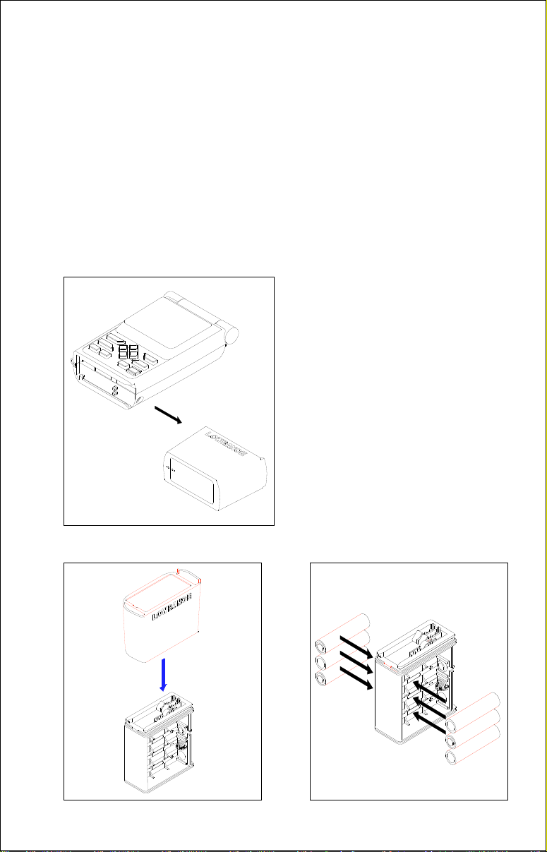
To install the batteries, first turn the
GlobalMap Sport™ so that it is facing you. Now grasp the bottom part
of the case and push it to the right
until it comes completely off the unit.
The bottom part of the case holds
the batteries. Next, push the battery
holder out the bottom of the battery
cover as shown below. Install each
battery with the negative end (-)
against the spring. The positive end
(+) of each battery should be firmly
against the metal plate. When all six
batteries are installed, slide the battery holder into the battery cover .
6
Page 7
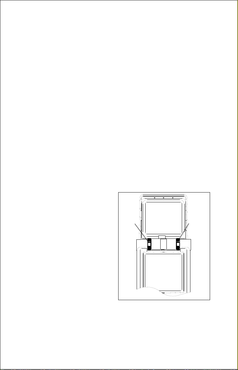
If the battery cover sticks when sliding into the battery cover, apply a thin
film of petroleum jelly to the “O” rings on the battery holder.
IMPORTANT!
There are arrows molded into the bottom of the battery cov er and battery
holder . Mak e certain the arrows are properly aligned! Otherwise, the battery holder won’t slide all the way into the cover and the battery pack
won’t slide onto the unit.
Slide the battery pack onto the unit and the GlobalMap Sport™ is ready
for use.
EXTERNAL POWER
Instead of batteries, the GlobalMap Sport™ can operate on 6 to 35 volts
DC from an external power source. To use exter nal power, an adapter
cable is supplied with your unit that will plug into your vehicle’s cigarette
lighter. To use this cable, simply plug one end into the GlobalMap Sport™
and the other end into the cigarette lighter. A rubber plug is supplied with
your GlobalMap Sport™ to cover the external power jack on the side of
the unit when it’s not in use.
ANTENNA
The GlobalMap Sport™ has a removab le antenna that f olds over the
display when the unit is not in use.
To open it, simply lift on an edge of
the antenna and raise it to the de-
LEFT
SCREW
RIGHT
SCREW
sired height.
Two thumbscrews on the antenna’s
hinge let you adjust the tension on
the antenna. This helps keep the
antenna in the desired position. The
thumbscrews work in opposite directions. To tighten the r ight thumbscrew, rotate it
away
from the display. To tighten the left thumbscrew,
rotate it
toward
the display.
Caution - Always make certain the left thumbwheel is tight when using
the GlobalMap Sport™. The connector for the antenna is inside the left
thumbwheel. If it isn’t tight, a poor connection can occur . This can pre v ent
the unit from operating properly , if at all.
7
Page 8
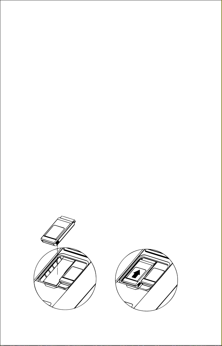
To remove the antenna, simply
loosen the thumbwheels until they
won’t turn. Carefully remo ve the antenna from the unit by pulling it
straight out. If you feel any resistance, make certain the
thumbwheels are at the end of their
trav el. Don’t force any parts!
You can see the antenna’s connector inside the left thumbwheel once
it’ s remov ed from the unit. When reinstalling the antenna, align the left
side of the antenna first, then
slowly
thread the left thumbwheel until it
engages the connector. This will require two full turns of the thumbwheel. After you’ve done this, thread the
right side of the antenna by rotating the right thumbwheel. Remember to
rotate the right thumbwheel in the opposite direction from the left.
Tighten the thumbwheels to get the desired tension on the antenna.
Caution - do not overtighten the thumbwheels .
ANTENNA ANGLE
When using the GlobalMap Sport™, try to make certain the antenna is
parallel with the ground, or nearly so as shown below. Since the signals
from the satellites are “line of sight”, a flat antenna gives you a better
ability to receive the signals from all of the available satellites.
Also, trees, buildings, and carports
can block the signals from the satellites. When using this unit in heavy
brush or timber, remember that it
may lose track on one or all of the
satellites until you mo ve into a clearing.
We have successfully used the
GlobalMap Sport™ in cars and
trucks since the satellite’s signal
passes through glass. Howe ver , antenna placement inside the vehicls
can make a difference in receiving
signals.
8
Page 9
MAP CARTRIDGE INSTALLA TION
The GlobalMap Sport™ uses both Lowrance IMS SmartMap™ and CMap cartridges, both of which are packaged in a cartridge housing specifically designed for Lowrance products.
The IMS cartridges contain digitized data of ov er 120,000 bodies of water .
Nearly all inland waterways-public and pri vate lak es, rivers, and streams ,
plus coastal United States waters up to 25 miles out are included. There
are also state and U.S . interstate highw ays and routes . These inland mapping cartr idges cover the entire continental United States in 64 highly
detailed cartridges.
The C-Map cartridges cover most of the world with detailed views of coastal
waters . Ov er 500 cartridges are av ailable .
The GlobalMap Sport™ can hold up to two map cartridges, in any combination: Two Lowrance IMS SmartMaps or two C-Maps, one of each, or
only one.
To install a cartridge into the GlobalMap Spor t™,
unit is turned off.
Never install or remove a cartridge with the unit
first make certain the
turned on! You can damage your unit if you install or remo ve a cartridge
with the unit turned on. Next, pry the cover off the back of the unit. Place
the cartridge into either slot with it’s label facing y ou as sho wn below . Now
slide the cartridge towards the top of the GlobalMap Sport™ until it stops.
Replace the cover and the cartridge is ready for use.
LEI IMS
TEXAS
EAST
LEI IMS
TEXAS
WEST
LEI IMS
TEXAS
EAST
LEI IMS
TEXAS
WEST
9
Page 10
REMOVING A CARTRIDGE
If you have difficulty removing a cartr idge, use the back cover as a removal tool. Simply press one side of the cover against the ridge on the
cartridge and gently push towards the bottom of the unit. Don’t use a
corner of the cover - it could damage it.
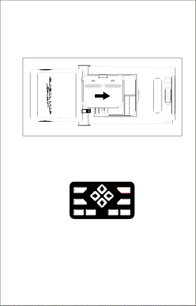
KEYBOARD
The key board has twelve keys. The arrow keys are tied to most of the
features, letting you easily move the mapping cursor, navigate through
the menus, mak e selections from menus , and other tasks.
MODE
MENU
Z-OUT Z-IN ENT PWR
WPT
EXIT
The WPT key lets you create , sav e , and recall wa ypoints and routes. The
MODE key switches the unit between the four major displays: windows,
position, navigation, and mapping. To select different features , or to modify
functions, press the MENU key. The Z-OUT and Z-IN keys z oom-out and
zoom-in your view on the mapping screen. The ENT and EXIT keys let
you enter or erase selections . The PWR key turns the GlobalMap Sport™
on and off.
Note: To tur n the unit off, you must hold the PWR key down for a few
seconds.
10
Page 11
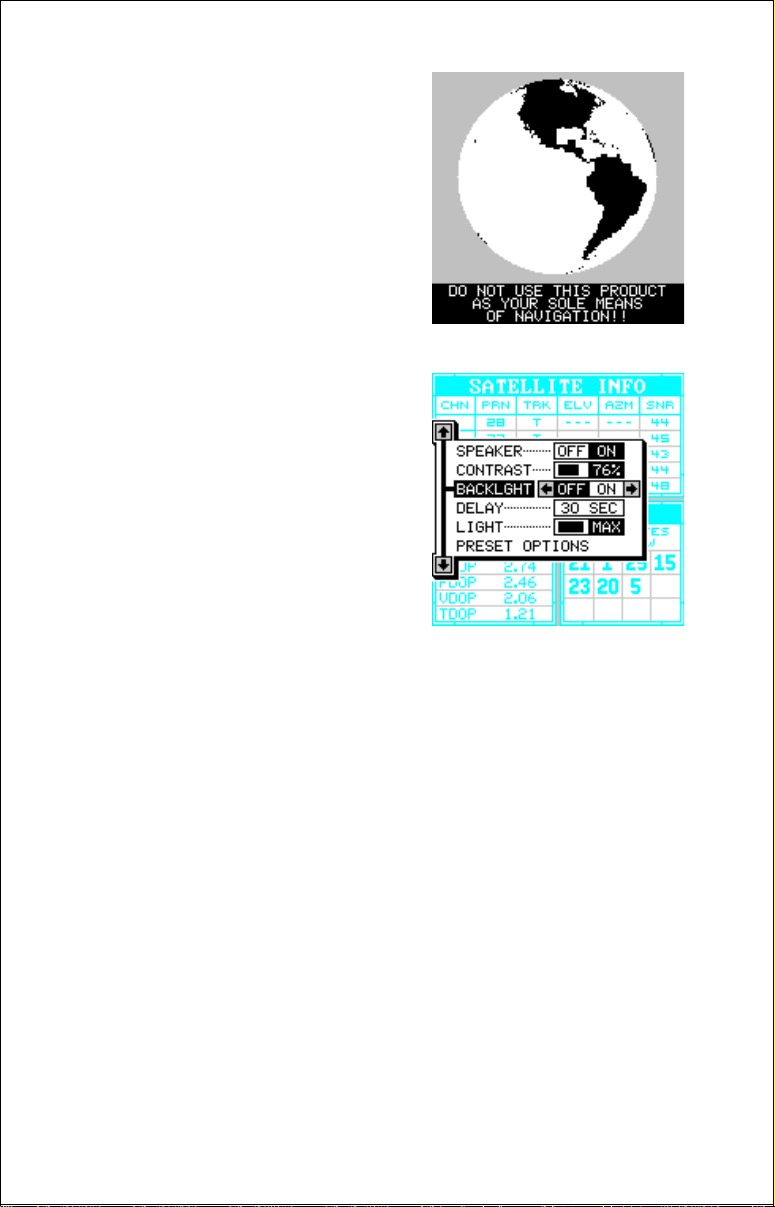
OPERATION
Turning Power On
To turn the GlobalMap Sport™ on, simply
press the PWR key . A screen similar to the
one at right appears. Read the message
on the screen, then press the EXIT key to
erase it. The GlobalMap Sport™ is now
ready for use.
MENUS
Most of the GlobalMap Sport™’s adjustments and features are f ound on “menus”.
Pressing the MENU key lets you view the
menus. Different menus items are added
to the basic list, depending on which mode
(mapping, navigation, or windo ws) the unit
is in. This gives you the features that are
specific to the mode you are in, but also
has items that are used on all modes.
To erase the menu, simply press the EXIT
key.
Finding Y our Position
Cold Start
When the GlobalMap Sport™ is turned on for the very first time, it doesn’t
know where it is, nor what the local time or date is. If you tell it your position, time, and date, the unit will take much less time to lock-on to the
satellites and give you a fix or position.
However, if you don’t want to push buttons at this time, that’s fine. The
GlobalMap Sport™ will lock onto the satellites and give you a position
without any input from you. This is called a “cold-start”. It simply means
that the unit is searching without help for the satellites that are in orbit. A
cold-start can take up to 15 minutes to acquire enough satellite data to
determine your position, although it typically takes less time than that.
Once the GlobalMap Sport™ locks on to the satellites and finds your
position, it stores the satellite data in its memory. The next time you use
the unit, it should take much less time to lock on.
11
Page 12
To use your GlobalMap Sport™, first take it outside, awa y from trees and
buildings. You need a clear view of the sky.
Open the antenna and adjust it so that it is
parallel with the ground. Press the PWR
key. Read the message on the screen,
then press the EXIT ke y to erase the message. A screen similar to the one at r ight
appears.
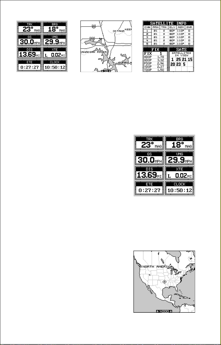
This is the Satellite Information screen. It
shows the fix quality, the satellites that are
currently in view from your position, and
the status of each of the five receiver channels. For more information on this screen,
see the satellite information section on page 20.
You can watch the GlobalMap Sport™ find the satellites on this screen, or
you can s witch to any other screen (press the MODE key to s witch screens)
while it’s searching.
If you switch to another screen, you’ll see numbers flashing on the displa y.
Anytime you see flashing n umbers, it means the GlobalMap Sport™ does
not have a position! Do not rely on any data that is flashing! When the
numbers stop flashing, the unit has locked on to the satellites and the
position is good.
That’s all y ou ha ve to do to find your position. The time displa y ma y not be
correct when the cold start method is used. See the initialization section
for details on changing the time .
Finding Y our Position
Initialization
A cold-start as described above can tak e
up to 15 minutes to find your position. A
faster method is to initialize the GlobalMap
Sport™ manually . To do this, first press the
PWR key. Next, read the message on the
screen and press the EXIT key to erase it.
Now press the MENU key. A screen similar to the one at right appears.
12
Page 13
Press the up or down arrow ke ys until the black
box surrounds the “GPS COMMANDS” menu
as shown at right. Now press the right arrow
key. The screen shown below appears.
Using the down arrow key , mo ve the b lack box
to the “Initialize GPS Receiver” menu, then
press the right arrow key. The screen shown
below appears.
This is the GPS setup screen. The position,
altitude, time, and date the GlobalMap Sport™
is currently using to find the satellites is shown
at the bottom of this screen. Changing these
values to y our local position and time will speed
the satellite lock much more.
To change the position, press the right arrow
key while the “EDIT LAT/LON” box is highlighted. The screen sho wn below appears.
If your latitude is south, press the up or down
arrow key to change it. If it is north, press the
right arrow key to mo ve the change box to the
first number in the latitude. Now press the up
arrow ke y to increase the number or the down
arrow key to decrease it. Once the first number in the latitude is set, press the right arrow
key once to move to the next number in the
latitude.
13
Page 14

Keep pressing the arrow keys until the latitude and longitude are set to
your local position. (Note: This position does not ha ve to be very accurate .
If you can get it within one degree of your actual position, that will be fine.)
When it’s set, press the ENT key. The GlobalMap Sport™ accepts your
entry and returns to the GPS setup menu.
Now change the local time and date if they’re incorrect on this screen.
(Don’t worry about altitude.) When everything is acceptable, press the
EXIT key to return to a mode screen. The GlobalMap Sport™ will instantly use the data you entered to find the satellites in the sky. (The unit
knows which satellites will be av ailable at the position, date , and time you
entered. Therefore, it will only look for those satellites , making the search
time much shorter than a cold start which looks for all of the satellites until
it finds three.)
Once the GlobalMap Sport™ finds and locks on to three satellites, it stops
flashing the numbers on the display. (Note: Altitude will still flash until the
unit locks on to the fourth satellite. It takes four satellites to determine
altitude.) It also sounds a tone, letting you know that it has completed the
search and is giving position data.
IMPORTANT!
If the data shown in digital numbers on any screen is flashing, it means
that data is inv alid. DO NOT RELY ON ANY NUMBERS THAT ARE FLASHING! Usually , this happens when the GlobalMap Sport™ has lost its lock
on the satellites. The data that is flashing was the last known when the
unit lost its navigational capability.
DO NO T NAVIGATE WITH THIS UNIT UNTIL THE DATA STO PS
FLASHING!
POSITION/NA VIGA TION DISPLAYS
The GlobalMap Sport™ has navigation, mapping, and windows group
modes. These screens were designed to show data that is used most
often. Many of the navigation, mapping, and
windows screens can be customized to show
data other than the ones chosen by the factory. See the Reprogram Groups section for
more details.
The three default displays are shown on the
next page. To change displays, simply press
the MODE key. A screen similar to the one at
right appears. Now press the up or down ar-
14
Page 15
NAVIGATION
MAPPING
(Map 1)
WINDOWS
(Group A)
row ke ys to change modes. (The windows display is shown as "Groups".
For example, Group A is the first windows group on the MODE menu.)
When the desired display appears, press the EXIT k ey to clear the men u.
Note: F or a list of ab bre viations used on the displa ys, see the bac k of this
manual.
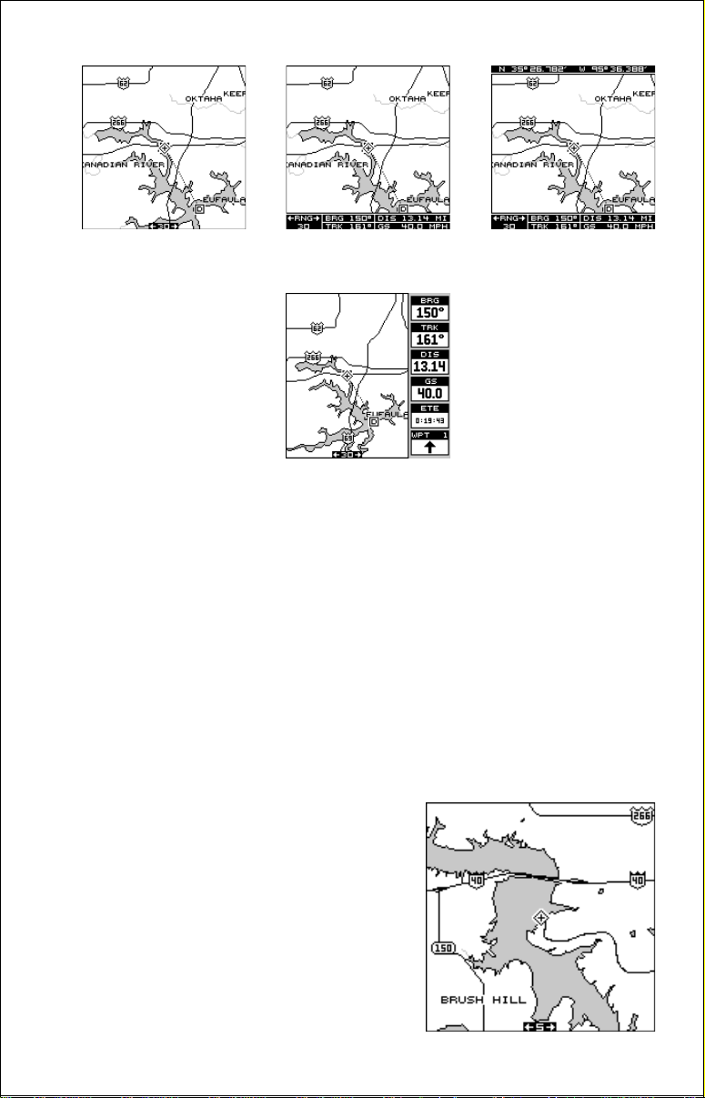
Navigation Screen
The navigation screen shows na vigation inf ormation in digital displays. To view this screen,
press the MODE key, then press the up arrow
key until the blac k box surrounds the “N a vigation” label. Now press the right arrow key. A
screen similar to the one at right appears. Press
the EXIT key to erase the mode menu.
This screen is composed of eight digital display bo xes , showing your trac k
(TRK) - direction of travel, ground speed (GS), and local time. The other
boxes show navigation data when a w aypoint is recalled. Although this is
not a windows screen, all of the digital boxes can be changed. See the
"Reprogram Groups" section f or more information.
Mapping
The GlobalMap Sport™ has a map of the world
built inside. This map has the majority of its
detail in southern Canada, the continental
United States and Hawaiian islands, the Caribbean down to and including the Virgin Islands,
all the way down to the northern coast of Honduras. It’s displayed when the GlobalMap
Sport™ is first turned on, with or without a map
cartridge.
15
Page 16
MAP 1 MAP 2 MAP 3
MAP 4
There are four diff erent mapping screens av ailabl e. Map screen n umber 1
shows by default. Your current position displays at the center of the screen
by a cross surrounded by a flashing diamond.
To view the other mapping screens, press the MODE key. Press the up or
down arrow key to move the black box to the "MAP 1" label. Now press
the right arrow or left arrow ke y to select a different mapping screen. Maps
2, 3, and 4 (as shown abov e) have na vigation data displa y ed using digital
numbers. Press the EXIT key to erase the mode menu.
The digital displays on map 4 can be rearranged or changed to other
displays. See the “Reprogram Groups” section f or more information.
As you move, the map slides past your
present position, which always remains at
the center of the screen. A line extends
from your position, showing the path y ou’ve
taken.
Use the Z-OUT and Z-IN keys to enlarge
or reduce the mapping area. If you have
an IMS SmartMap™, it’s detail will usually
begin showing when you zoom in to the
10 mile range.
16
Page 17
If you z oom-in below the 5 mile range into an area not covered b y a detail
cartridge, the map data disappears, turning the screen into a plotter. If
desired, you can turn the map off, turning the mapping screen into a plotter only on any range. To do this, press the MENU key, then press the up
or down arrow k eys until the b lack bo x is on the “Mapping” label. Press the
left arrow key to turn the map off.
Map Cursor
Pressing an arrow ke y while a map is on shows
two dotted lines that intersect at your present
position. These dotted lines are called a “cursor” and have a variety of uses.
You can move the cursor around the display
by pressing the arrow k eys in the direction yo u
want it to mov e. This lets you view diff erent areas of a map, away from your present position. When it’s turned on, the zoom-in and
zoom-out keys work from the cursor’s position - not the present position,
so you can zoom in on any detail, anywhere while navigating.
The latitude/longitude of the cursor shows in the box at the top of the
screen whenever the cursor is activated.
To center the cursor on the map, press both the Z-IN and Z-OUT keys at
the same time. Remove the cursor by simply pressing the EXIT key. T h e
GlobalMap Sport™ moves the present position diamond to the center of
the screen and erases the cursor.
The map cursor is also used to place and erase icons and waypoints.
MAP MENUS
To view the map menus, first press the MENU key, then press the up or
down arrow keys until the desired menu appears as sho wn below. When
it does, press the right arrow key to view the
items on the selected menu.
PLOTTER OPTIONS
Plot Trail
The line extending from your present position
is called a plot trail. The GlobalMap Sport™
lets you customize the plot trail with the f ollo wing menu items. All of the items on the Plotter
Options menu affect the plot trail.
17
Page 18
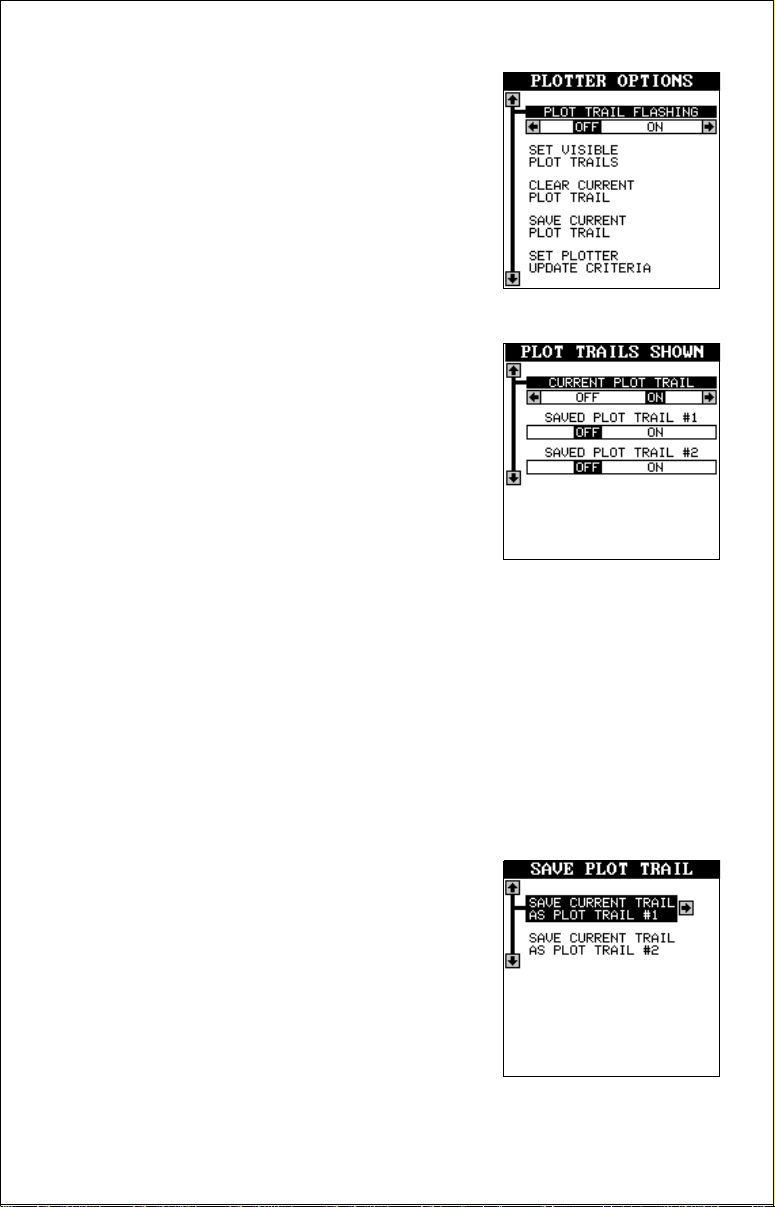
Plot Trail Flashing
Since there can be many lines on the mapping display, it’s helpful at times to make the
plot trail flash. This makes it easier to see. To
do this, move the black bar to the “Plot Trail
Flashing” menu, then press the right arro w key.
Press the EXIT key to return to the map. Repeat the above steps to turn the flashing off.
Set Visible Plot T rails
The plot trail can be turned off, if desired. To
turn it off, press the up or down arrow ke y until
the “Set Visib le Plot Tr ails” menu is surrounded
by the black box. Now press the right arrow
key. The screen at right appears.
Use the up or down arrow keys to select the
desired plot trail, then press the left or right
arrow k e y. Press the EXIT key to return to the
Plotter Options menu.
Clear Current Plot T rail
To erase the plot trail extending from your present position, move the
blac k box to the “Clear Current Plot Trail” menu, then press the right arrow
key. A message box appears, asking you if you really want to erase the
plot trail. F ollow the directions on this message box. The GlobalMap Sport™
returns to the mapping screen after the message box clears.
Save Current Plot Trail
You can save up to two plot trails in the GlobalMap Sport™’s memory. It
saves these trails even if power is removed from the unit.
To save your current plot trail, mo ve the blac k
box to the “Save Current Plot Trail” menu using the arrow keys. Now press the right arrow
key. A screen similar to the one at right appears.
You can save the plot trail as #1 or #2. Move
the black box to the desired plot trail number,
then press the right arrow ke y . A message bo x
appears asking you if you really want to save
the trail. Follow the instructions in this box. The GlobalMap Sport™ re-
18
Page 19
turns to the mapping screen after the message box clears. Your plot trail is
now stored in memory.
To view your sav ed plot trail, see the “Set Visible Plot Trails” section.
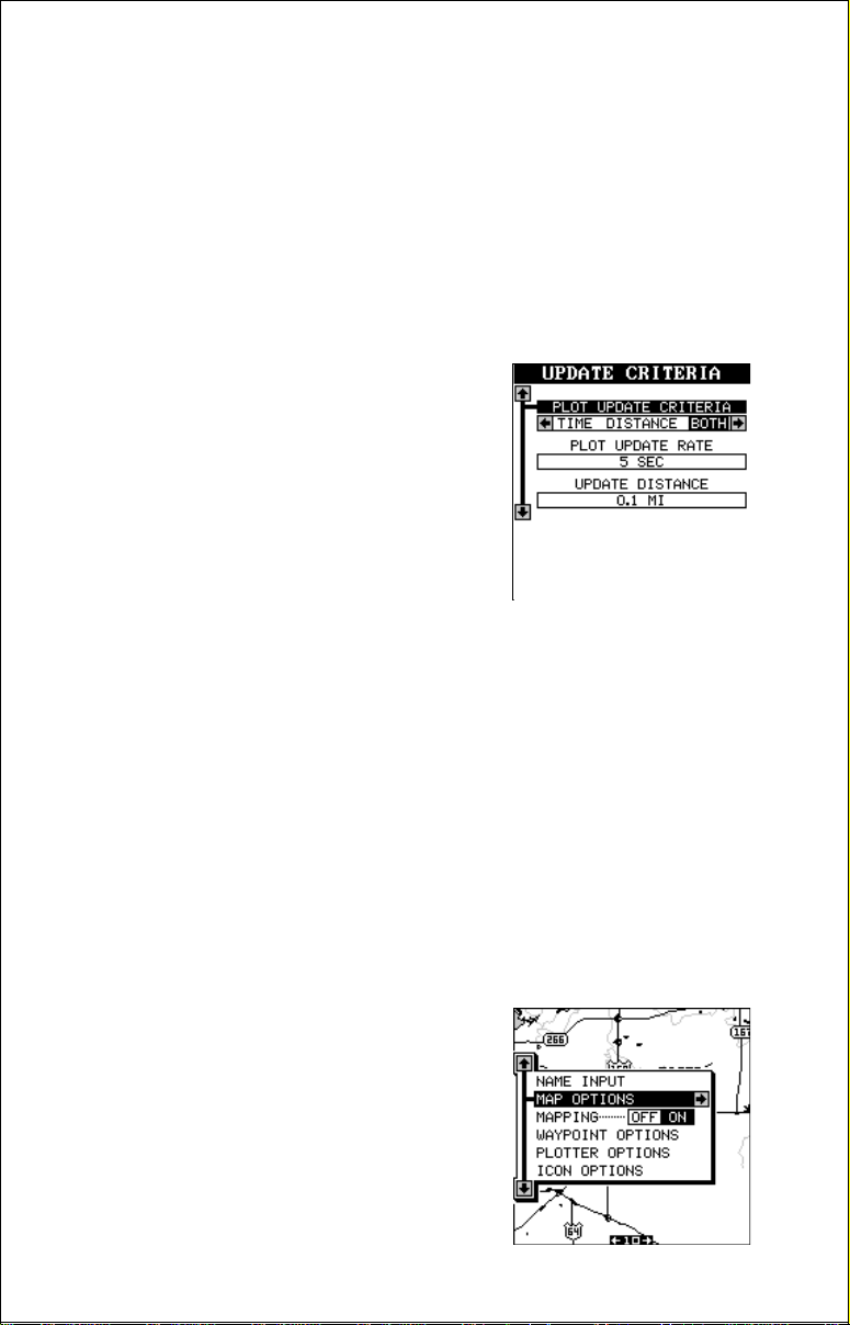
Set Plotter Update Criteria
The plotter places a dot on your trail as you move. It determines when to
place a dot depending on two things: time and distance. By default, it
places a dot every five seconds or every .1 of a mile, whichever comes
first.
To change the update, move the b lack bo x (using the arrow keys) to the “Set Plotter Update
Criteria” menu item, then press the right arro w
key. A screen similar to the one at right appears.
T o limit the update to time only, or distance only,
press the left arrow key until the black box is
on the desired setting.
Change the update rate by mo ving the blac k box to the “Plot Update Rate”
menu, then press the left or right arrow keys until the desired time appears.
The distance update is changed in the same manner. Move the black box
to the “Update Distance” men u, then press the left or right arrow keys until
the desired distance appears.
When you hav e e v erything on this menu adjusted to the desired settings,
press the EXIT key to enable them.
MAP OPTIONS
This menu gives you a variety of options to
customize your mapping screen. To use these
options, first press the MENU key while a map
is displayed. Next, press the up or down arrow
keys the black box surrounds the “Map Options” label. Press the r ight arrow key to view
this menu.
19
Page 20

Text Labels
Use this menu to turn the names on the map
off or on. The default is “on”. Press the left arrow key to turn them off.
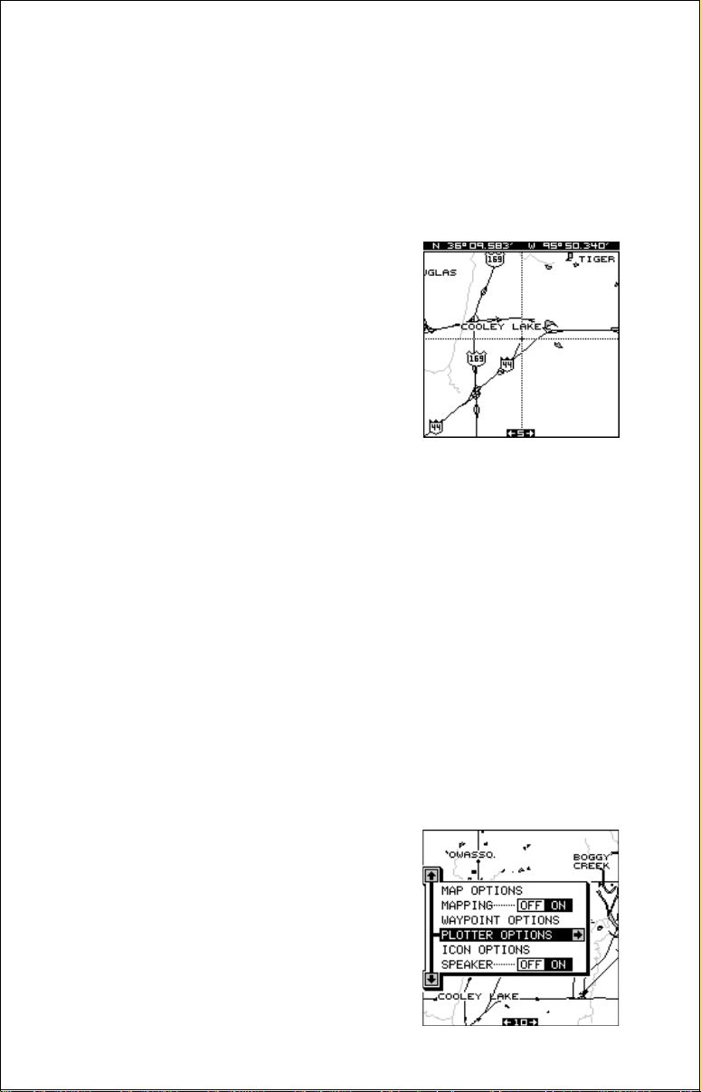
Map Boundaries
If you have a map cartridge plugged into the
back of the GlobalMap Sport™, this feature will
show the boundaries of the cartridge on the
map. This lets you know the exact area cov ered by your cartridge. This example shows
the boundaries of the Oklahoma - East Inland
Mapping System cartridge.
Fill With Gray
When the GlobalMap Sport™ is first turned on, all water is filled with gray
to distinguish it from land, which is clear. To make the land fill with gray
and water remain clear , press the do wn arrow k ey until the “Fill With Gray”
menu is surrounded by the blac k bo x, then press the left arro w ke y. Press
the EXIT key to return to the mapping screen.
FILL WITH GRAY - LANDFILL WITH GRAY - WATER
You'll generally want to fill water with gray when y ou're using the GlobalMap
Sport™ on land and fill land with gray when you're using it on the water.
20
Page 21

Track Up Mode
Normally , the GlobalMap Sport™ shows the map with north always at the
top of the screen. This is the way most maps and charts are printed on
paper. This is fine if you’re always travelling due north. What you see to
your left corresponds to the left side of the map, to y our right is shown on
the right side of the map, and so on.
However, if you travel any other direction, the map doesn’t line up with
your view of the world.
To correct this problem, the GlobalMap Sport™ has a track-up mode that
rotates the map as you turn. Thus, what you see on the left side of the
screen should be to your left, and so on.
COURSE-UPNORTH-UP
In the above example, we're travelling southwest on Interstate 44. In the
north-up view, the present position indicator appears to move to wards the
lower left corner of the display. In the track-up view, the present position
moves tow ards the top of the display. A "N" shows to help you see which
direction is north when the track-up mode is on.
(Note: the track-up mode does not work when the unit is zoomed-in on a
C-Map cartridge.)
To select the track-up mode, press the up or do wn arrow ke ys to mov e the
black bo x to the “Track Up Mode”, then press the right arrow k ey to turn it
on. Press the EXIT key to return to the mapping screen.
Detail Cartridge
The GlobalMap Sport™ can use either Lowrance Inland Mapping System cartridges or Lowrance C-Map cartridges. You can have one of each
in the unit at the same time, howe ver you can only use one or the other.
21
Page 22

To switch between Lowrance and C-Map cartridges, press the up or down
arrow keys until the “Detail Cartr idge” menu is surrounded by the black
box, then press the left or right arrow ke ys to select the desired cartridge.
Press the EXIT key when you’re finished.
ICONS
The GlobalMap Sport™ has fifteen symbols or “icons” available. These
icons can be placed anywhere on the mapping screens. These can be
used to mark fishing spots, boat ramps, rest stops, airports, or whatever.
You can place an icon at your present position, or at the cursor location.
Before you can view icons on the map, you
must first turn the icons on. T o do this, first press
the MENU key, then use the up or down arrow
keys to move the black box to the “ICON OPTIONS” box. Now press the right arrow key.
The screen shown at right appears. The black
box is on the “Icon Symbols” menu. Press the
right arrow key. This turns the icons on. Press
the EXIT key to erase this menu and return to
the mapping screen.
Place Icon - Present Position
To place an icon at your present position, simply press the ENT key. The screen shown below appears. Use the arrow keys to move the
black box to the desired icon. Now press the
ENT key. The mapping screen appears with
the icon you selected placed at your position
when you first pressed the ENT key, not your
present position.
MAP - BEFORE PLACING
ICON
MAP - AFTER PLACING
ICON
22
Page 23

Place Icon - Cursor Location
To place an icon at cursor's location, first use the arrow keys to move the
cursor to the position that you want to place the icon. Next, press the ENT
key. Now select the desired icon using the arro w k eys. When it's selected,
press the ENT key. The mapping screen re-appears with the icon at the
cursor's location. Press the EXIT key to erase the cursor.
MOVE CURSOR TO
LOCATION
PRESS ENT, SELECT
ICON, PRESS ENT
PRESS EXIT TO ERASE
CURSOR
Erase Icons
To erase an icon from the screen, first press the MENU key, then select
the “Icon Options” menu as shown at the top of the previous page.
There are three methods used to erase icons from the screen. You can
delete all of the icons, regardless of their position on the displa y , delete all
of the icons of a certain type, or selectively erase individual icons.
To erase all of the icons, move the black box to the “Delete All Icons”
menu, then press the right arrow key. A message appears, asking you if
you want to delete all icons. Press the left arrow key to erase them. The
unit returns to the mapping screen with all icons deleted.
To remove only icons of a certain type, move the black box on the Icon
Options menu to the “Delete Icons By Type” label. Press the right arrow
key. The icon selection menu appears. Use the arrow keys to move the
black box to the icon style that you wish to erase. Press the ENT key
when you’re ready to erase the icons. A message appears, asking you if
you want to delete the icons of that type. Press the left arrow key to erase
them. The unit returns to the mapping screen with all icons of the type y ou
selected erased.
To remove only certain icons, move the black box on the Icon Options
menu to the “Delete Icons From Map” label. Press the right arrow key. The
unit returns to the mapping screen with the cursor centered on your present
position. Use the arrow keys to move the cursor to the icon on the map
23
Page 24

that you wish to erase. Press the ENT key when you’ re ready to erase the
icon. A message appears, asking y ou if you want to delete that icon. Press
the left arrow ke y to erase it. If you wish to delete another icon, move the
cursor over it and press the ENT key. When you’re finished, press the
EXIT key to erase the cursor.
WINDOWS
The windows feature gives you over 45 different displays that you can
arrange in 15 different groups. This lets you customize the unit to your
own situations.
To use the windows feature, press the MODE
key, then press the up or down arrow k eys until
the blac k box surrounds the “GROUP A” label
as shown below . Windo ws has 15 diff erent preprogrammed groups: A through O. Group “A”
is visible in the background when you switch
to the windows groups. To view each group,
simply press the right or left arrow key while
the mode menu is showing. Each group show s
in the background as y ou press the arrow ke ys.
When you see the group you want to use, simply press the EXIT key to
erase the mode menu.
Special Windows
Although most of the windows used in the GlobalMap Sport™ are selfexplanatory, there are several windows that have special features or can
be used in unique ways. The following section describes these windows.
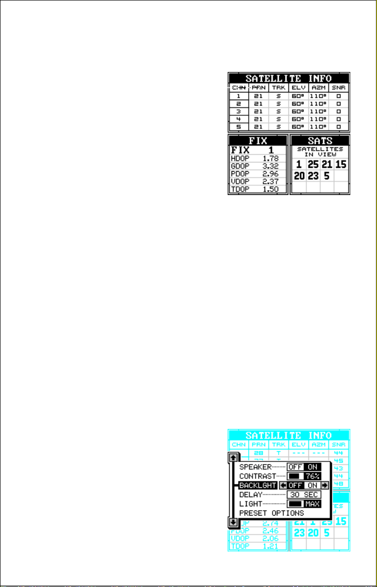
Satellite Information Screen (Group A)
This screen shows technical inf ormation about
the status of the GPS receiver. The receiver
has five channels. Data for each channel is
shown at the top of the display. The channels
are numbered one through five on the left side
of the screen. Every satellite in the constellation has a number assigned to it, called the
PRN. The TRK column shows a "T" if the channel is tracking the satellite , or a "S" if it is searching for it. ELV is the elevation of the satellite
above the hor izon; AZM is the azimuth, or direction from your location.
SNR is the signal-to-noise ratio. The higher the SNR, the better.
If you look at row one in the satellite info screen above, channel 1 is
24
Page 25

tracking satellite number 28. The satellite's elev ation is 25 degrees abov e
the horizon and it's location is 44 degrees . It's SNR is 44, which is good.
The FIX numbers in the lower left corner of the screen show the quality of
fix. If the FIX is 9, then it's the best you can get. A FIX of 1 is the w orst. The
DOPS display beneath the fix quality show you the "Dilution of Precision"
for the horizontal (HDOP), geometric (GDOP), position (PDOP), time
(TDOP), and vertical (VDOP). The GDOP is a combination of HDOP, VDOP,
and TDOP. The smaller the DOP's value, the better. The receiver selects
satellites based on the GDOP value, therefore, it always tries to use satellites that have good DOP values. These depend on the azimuth and
elev ation of the satellite, and any ground based obstructions.
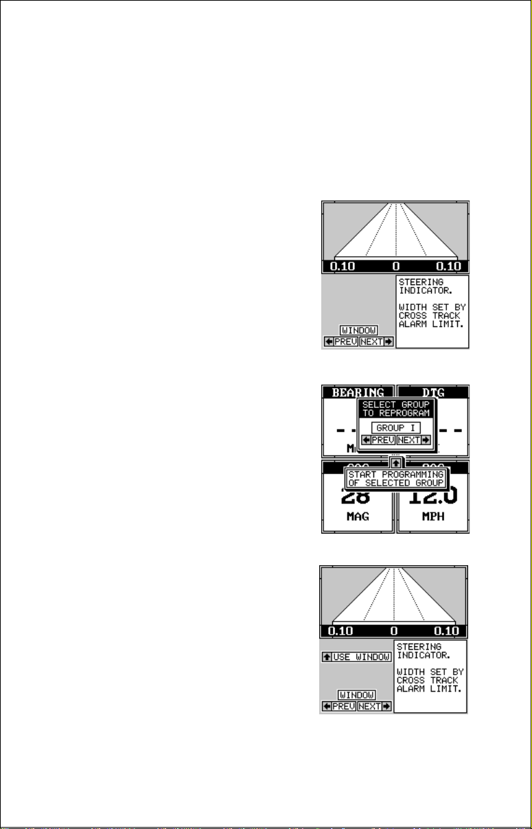
Steering Screen (Group F and O)
The steering screen shows a pictorial view of your course and the distance to the side of the desired track to a waypoint. You must recall a
waypoint to use the steering screen.
Your present position is shown by a pointer near the center of the steering
screen as shown in group "O", abov e . It shows the direction you're heading in relation to the waypoint. If you keep the pointer aimed at the top of
the display and centered in the middle, you'll reach the waypoint in the
shortest straight line.
The solid line extending from the pointer is the path y ou'v e taken. To travel
directly to a waypoint, try to keep the pointer on the center line. As you
approach the wa ypoint, a circle desends from the top of the steering screen.
This represents the waypoint.
Small numbers on the left side of the steering screen show the distance
from your present position to the recalled waypoint. If the numbers are
surrounded by a black b ox, then that is the distance
past
the waypoint.
The large numbers at the bottom of the screen show the distance you're
25
Page 26

off course to the right or left. This is called "Cross Tr ack Error". For example, if the pointer is halfwa y between the center line and the left outside
line, and the range is 0.10 miles, then you are off course to the left of the
desired path by 0.05 miles. In other words, your cross track error is left
0.05 miles. You can change the range by changing the cross track error
(XTE) alarm. See the GPS alarms section for more information.
Dual Mapping
The windows feature gives you the capability
to have more than one map on the display at
one time. For example, group "M" shown at
right has two half-screen maps, side-by-side.
Both of these maps are completely independent of each other. In other words, you can
zoom in or out, set options, and other functions on one map, without affecting the other.
When you press the menu, zoom in or out, or
ent ke ys, a message appears asking you which
display y ou want to aff ect. On the screen shown
at right, the menu key was pressed. The unit
wants to know which map you w ant to change.
Press the left arrow key for the left map, the
right arrow key for the right map. The main
menu then appears.
CLOCK
Whenever a clock is showing on a display,
new items appear in the list when you press
the MENU key. These items let you set the
clock’ s time, set alarms, and change the unit
of measure. The clock and timers can be
used on windows, mapping, or the navigation mode.
Clock Set
If the time shown on the clock display is not your local time, change it
using the “Cloc k Set” function. To do this, press the MENU key, then press
the up or down arrow keys until the b lack box is on the “Clock Set” label.
Press the right arrow key. A screen similar to the one at the top of the ne xt
page appears.
26
Page 27

Using the right and left arrow keys, move
the blac k bo x to the first number in the time
that you want to change. Now press the up
or down arrow keys until the desired number shows. Continue until the time sho wn in
the display is correct, then press the ENT
key . The unit returns to the navigation, mapping, or windows display with the new time
showing.
Clock Hours
Normally , the time sho ws in the twelve hour f ormat (a.m./p .m.). To change
it to 24-hour format, press the MENU key, then select the “CLK HRS”
label. Now press the right arrow key to change it to 24, then press the
EXIT key.
Clock Alarm
You can set an alarm (that works just like
an alarm clock), by using the “Clock Alarm”
menu. To set this alar m, press the MENU
key, then move the b lack bo x to the “Clk Alm
Set” label. Press the right arrow key. A
screen similar to the one below appears.
Using the right and left arrow keys, move
the blac k bo x to the first number in the time
that you want to set. Now press the up or
down arrow keys until the desired number
shows. Continue until the time shown in the
display is correct, then press the ENT key. The unit returns to the navigation, mapping, or windows display.
To turn the alar m on, press the MENU key, then select the “CLK ALM”
menu. Press the right arrow key. The alarm is now activated.
When the alarm goes off, an audible tone sounds along with a flashing
message on the screen. Press the EXIT key to turn the alarm off.
Note: The GlobalMap Sport™ must be on in order for the alarms to work.
In other words, if you set the alarm to go off at 7:00 a.m., then the
GlobalMap Sport™ will have to be on at 7:00 a.m., also.
27
Page 28

TIMERS
The GlobalMap Sport™ has two timers built
in. One is a count-down timer and the other is
a count-up timer. The count-down timer counts
down from the time you put in to zero. The
count-up timer starts at zero and counts up to
the time you entered.
To set either timer, first switch to a screen that
is showing the timer that you want to use . Ne xt,
press the MENU key, then move the black bo x
to the desired timer set menu. In this example,
we’ re setting the count-down timer . Now press
the right arrow key. A screen similar to the one
below appears.
Using the right and left arrow keys, move the
black box to the first number in the time that
you want to set. (The time is in hours, minutes ,
and seconds) Now press the up or down arrow ke ys until the desired number shows. Continue until the time shown in the display is correct, then press the ENT key. The unit returns
to the navigation, mapping, or windows display.
To start the timer, press the MENU key, then
move the black box to the “Dn Timer STOP/
GO” label. Press the r ight arrow key to start
the timer. The timer continues counting until
you stop it. If you turn the up timer’s alarm on
(press the right arrow key when the b lac k box
is on the (Up ALM...Off/On label), it will sound
a tone when it reaches the time you entered in
the up timer set menu. Press the EXIT key to
silence the alarm.
28
Page 29
You can reset either alarm to the time you originally set by pressing the
MENU key, then moving the black box to either the “Up Timer Reset” or
“DN Timer Reset” label, then press the right arrow key.
REPROGRAM WINDO WS GROUPS
All of the 15 windows groups can be customized. The changes you make
to the groups will remain in memory, e v en if all power is removed from the
unit. You can, however, return the groups to the factory settings from the
“Preset Groups” menu.
Before you reprogram a group, you may wish
to view all of the possible windows that make
up the windows groups. To do this, press the
MENU key while a windows g roup is showing.
Now mov e the black bo x to the “View Windows”
label and press the right arrow key. The first
window appears along with it’s description.
Continue pressing the right arrow key to see
more windows. When you’ re finished, press the
EXIT key.
To customize a group, first s witch to a windows
group. It doesn’t ha ve to be the group y ou want
to customize. Ne xt, press the MENU ke y, then
press the up or down arrow key until the “Reprogram Groups” menu is surrounded by the
black box. Press the right arrow k ey. A screen
similar to the one shown at right appears.
You’ll see the group selection menu at the top
of the screen. Using the left or right arrow keys,
choose the group you want to change. When
the desired group letter is showing in the box
(and in the background), press the up arrow
key to change it. A screen similar to the one at
right appears.
The first window appears on this screen. A description of the window
appears in a box on this screen, also. If you wish to use it, simply press
the up arrow k ey. The unit flashes a message on the screen, telling you it’ s
29
Page 30

adding the new window to the group . When it’ s
finished, it returns to the window selection
menu. You can now press the right or left arrow keys to select the ne xt window in the group .
When you’re finished selecting windows
fore
filling the group with windows, press the
be-
EXIT key. If you fill the g roup with windows, the
unit will automatically leave the reprogram
groups menu after the last window is selected.
Note:The digital boxes on the navigation and map #4 screens can also
be re-programmed. Follow the same steps show above to program the
navigation and map screens. (The menu label is called “Reprogram Bo xes”
for the na vigation and map screens.)
RESET GROUPS
To return all groups to their factory defaults, press the MENU key, then
press the up or down arrow keys until the black box is on the “PRESET
GROUPS” menu. Now press the right arrow key. All groups are now reset
to their factory settings.
BACKLIGHT
The GlobalMap Sport’s™ display and keyboard have lights that can be
turned on for night use. Although there is a menu item “Backlight”, the
easiest way to turn the lights on is to simply press the PWR key. To turn
them off, press the PWR key again.
If the unit is operating from the battery pack, it automatically turns the
lights off after 30 seconds. This helps conserve battery power . The time is
adjustable from 5 seconds to 240 seconds. Press the PWR ke y to turn the
lights on after the unit turns them off.
To change the backlight’s delay time, press the
MENU key, then press the up or down arrow
keys until the “Delay” menu is surrounded by
the blac k box. Now press the left or right arrow
ke y until the desired time appears on the menu.
Press the EXIT key when you’re finished.
The backlights brightness is also adjustable.
To do this, press the MENU key, then press
the up or down arrow keys until the “Light” menu is surrounded by the
black bo x. No w press the left or right arrow ke y until you ha v e the lights at
the desired level. Press the EXIT key when you’re finished.
30
Page 31

UNITS OF MEASURE
The GlobalMap Sport™ can show its data in many different formats. For
example, distance can be displayed in statute miles (MI), nautical miles
(NM), or kilometers (KM).
The following can be changed on the Units of Measure menu:
Distance .................. miles, nautical miles, kilometers
Speed...................... miles per hour, knots , kilometers per hour
Bearing.................... magnetic, true
Altitude .................... feet, meters
Clock....................... 12-hour (a.m.-p.m.), 24 hour
P osition Format .......degrees, minutes , and tenths of a minute
degrees, min utes, seconds
UTM
To change a setting on this menu , move the
black box to the desired selection, then press
the left or right arrow key. You can change one
or all of the settings on this page. When y ou’ re
finished, press the EXIT key.
Note: See the following on the position format
and UTM’s.
Position Format
To change the position format, move the black box to the “Position Format” label on the Units of Measure menu, then press the right arrow key.
A screen similar to the one below appears.
The GlobalMap Sport™ can show the position in degrees, minutes, and hundredths of a
minute (36 28.700') or degrees, minutes, and
seconds (36 28' 40.9". It can also show position in UTM’s or Univ ersal T ransverse Mercator
projection.
UTM’s are marked on USGS topographic
chart s. This system divides the Earth into 60
zones, each approximately 6 degrees wide in
longitude. Their unit of measure is in meters. For example, 15 N means
that the position shown to the right of the “N” is in g rid 15, and it’ s north of
the equator.
31
Page 32

Press the up or down arrow keys to move the black box to the desired
position format. Press the EXIT key to both select the format and erase
the position format menu.
TRACK HOLDING
When using a GPS receiver at low speeds, it can have trouble determining your course ov er ground, or direction you’ re
travelling. This is due in large part to SA, or
selective availability. SA is small inaccuracies
purposefully put into the GPS satellite’s signal
by the gov ernment. This cause wide variations
in the track display and other navigation displays when using the unit at slo w speeds.
If you’ re using the GlobalMap Sport™ without
DGPS at speeds below 10 miles per hour, a
track holding feature begins slowing the update of your course over ground. At 3 mph, it locks the trac k dispaly to the
last know heading. With DGPS, it begins at 5 mph and locks at 1 mph.
(Note: This only affects the map when it’s in the track-up mode. It always
affects the navigational displays.)
To turn the track holding feature off, press the MENU key, then move the
black box to the “GPS Corrections” label and press the right arrow key.
The screen shown at right appears. Press the left arrow key to turn track
holding off. Press the EXIT key to erase this menu.
DATUM
Maps and charts are based on a survey of the area that’s covered by the
map or chart. These surveys are called “Datums”. Maps that are created
using different datums will show the same latitude/longitude in slightly
different locations .
All datums are named. The GPS system is based on the WGS-84 datum,
which covers the entire world. Other datums may also cover the entire
world, or just a small portion. By default, the GlobalMap Sport™ shows
your position on the map using the WGS-84 datum. However , it can show
your position using one of 99 different datums.
To change the datum, first press the MENU key, then move the b lack box
to the “GPS Correction” label. Press the right arrow key. Using the up or
down arrow keys, move the black box to the “Select Datum” label. Now
32
Page 33

press the right arrow key again. A screen similar to the one at right appears.
The black bo x is resting on the WGS-84 label.
To change it, simply press the up or down arrow keys until the black box is on the desired
datum, then press the ENT key. This selects
the datum and erases the select datum menu.
The GlobalMap Sport™ is now using the datum you selected.
PCF (Position Correction Factor)
Another method used to make your displa y match a chart or map is called
“PCF” or Position Correction Factor. This unit gives you the capability to
move or offset the position shown on the display to match one on the
chart. The unit will add this offset to all position and navigation displays at
all times.
Remember, the position error on any r adio navigation system is very dynamic and the PCF offset should never be used in an attempt to cancel
the error .
In general terms, PCF should only be used if your map indicates what the
possible error is. PCF should always be reset to zero when you’re
finished with the chart.
For example, suppose you are stopped at a location that is accurately
marked on a chart. Your unit shows a longitude position that is .244 minutes east of the one on the chart and .047 minutes north latitude. Using
the PCF feature, you can make the GlobalMap Sport™ match the chart
you’ re using. If you mov e, the unit will continuously add the change to all
position, navigation, and mapping displays. This makes it more closely
match the datum used by the chart. F or this reason, you should be careful
when entering the PCF offset. It’s saved in memory and doesn’t change
when the unit is turned off. Ho wev er , resetting
the unit does erase the PCF offset.
To set the PCF offset, first press the MENU
key , then press the up or do wn arrow k eys until
the black box is on the “GPS Corrections” label. Press the right arrow key. Now move the
black bo x to the “Set Position Correction Factor” label and press the right arrow key. The
screen shown at right appears.
33
Page 34

Now enter the correction for your location. Remember, this is the difference between the location shown on the present position displa y and the
position shown on the chart. In this e xample, we entered 0 degrees, 0.047
minutes north latitude and 0 degrees, 0.244 minutes east longitude. That
is the difference between the present position shown by the GlobalMap
Sport™ and the one on our chart.
After you’ve entered the latitude/longitude correction, press the ENT key
to accept it. The GlobalMap Spor t™ erases the PCF entr y screen and
returns to the navigation or mapping screens with the correction factor
applied.
SYSTEM INFO
The system information screen shows the release date and the version n umber of the code
stored inside the GlobalMap Sport™. To view
this screen, press the MENU key, then press
the up or down arrow keys until the “System
Info” menu is surrounded b y the blac k box. Now
press the right arrow key. A screen similar to
the one below appears. Press the EXIT key
when you’ re finished reading this screen.
GPS COMMANDS
The GPS Commands menu has five sub-menus that affect the GPS receiver. From these menus you can turn the simulator on or off, set the
update rate, initialize the GPS receiver, do a self-test on the receiver, and
do a cold-start. (Note: The “Initial GPS Module” is covered in the “Getting
Started” section in the front of this manual.
To view these menu items, press the MENU
key, then press the up or down arrow keys until
the “GPS Commands” menu appears. Press
the right arrow ke y . A screen similar to the one
at right appears.
GPS Simulator
A simulator is built into the GlobalMap Sport™ that runs a pre-set course
off the Florida coast near Miami. When the present position reaches the
end of the course, the plot trail is erased and the simulator starts over . You
can use nearly all of the unit’s features - e ven save and recall waypoints.
34
Page 35

To turn the simulator on, press the up or down arrow keys until the “GPS
Simulator” menu is surrounded by the blac k box. Now press the right arrow key. Press the EXIT key to erase this men u.
Note: Your plot trail will be erased when you turn the simulator on or off.
GPS Update Rate
Changing the update rate conserves battery p ower and lengthens the
battery life. The update rate is the length of time it takes the receiver to
send data to the display. In other words , normally the receiver sends position data out once every second. You can reduce that time to once every
five seconds. However, slowing the update rate also makes it harder to
use this product at slow speeds, such as hiking or sailing. The faster the
update rate, the better the unit can respond to changes in direction or
speed.
If you wish to change the update rate, simply move the black box to the
“GPS Update Rate (SEC)” menu, then press the left or right arro w ke y to
move the black box over the desired rate: 1, 2, 3, 4, or 5 seconds. Press
the EXIT key to activate your selection.
Execute GPS Self Test
If you suspect a problem with the GPS receiv er,
or just wish to test it, move the black box on
the GPS Commands menu to the “Execute
GPS Self Test” label, then press the right arrow key. A screen similar to the one at right
appears after several seconds. Messages at
the bottom of the display will tell you if the unit
passed the self-test, or failed. If the unit fails
the self-test, contact the Lowrance customer
service department.
Execute GPS Cold Start
When the GlobalMap Sport™ is turned on for the first time “out of the
box”, it automatically sends a “cold-start” message to the GPS receiver.
You can also send a cold start message to the receiver at any time.
If the unit can’t lock on to the satellites using the data you’v e g iv en it, or if
it has trouble finding the satellites , perhaps it is using the wrong data. This
can happen if you’v e entered the wrong data by accident when initializing
the receiver. For example, if you entered east longitude instead of west.
Or if you’ve moved a long distance with the unit turned off.
35
Page 36

To send a cold start message to the receiver, move the black box on the
GPS Commands menu to the “Execute GPS Cold Start” men u, then press
the right arrow key. A message appears, asking you if you really want to
do a cold start. Follow the instructions on this message page.
The unit will begin searching for the satellites. It can take as long as 15
minutes for it to lock on to the necessary satellites, but it usually takes
much less time. Remember, when it does, your local time and possibly
date can be wrong. Use the method shown in the initialization section at
the front of this manual to change them, if needed. Once this is done, an
internal clock will keep the correct time, even when the unit is turned off.
The GPS system updates this clock when the unit is locked on to the
satellites.
GPS ALARMS
The GlobalMap Sport™ has three different alarms. An arrival alarm sounds
a warning tone when you cross a preset distance from a waypoint. For
example, if you have the arrival alarm set to .1 mile, then the alarm will
sound when you come within .1 mile of the recalled waypoint. The cross
track error alarm (XTE) sounds a warning when your track drifts too far to
the right or left of the line to the waypoint. For example, if the alarm is set
to .1 mile, then the alarm will sound if you drift .1 of a mile or more to the
right or left of the line to the wa ypoint. The anchor alarm sounds a warning
when you drift outside of a preset radius. Again, using the .1 mile as an
example, if you’re anchored and the boat moves more than .1 of a mile,
the alarm will sound.
Important Alarm Notes:
Anchor Alarm - Since civilian users don’t receive the accuracy given to
military users, the anchor alarm may sound even when you’re sitting still.
This typically happens when using small (less than .05 mile) anchor alarm
ranges. If you have a DGPS beacon receiv er connected to the GlobalMap
Sport™, smaller ranges may be useable.
Arrival Alarm - If you set the arriv al alarm’s distance to zero (0), and you
run a route (see the routes section), the GlobalMap Sport™ may not show
navigation data to the next w aypoint, once y ou arriv e at the first one. If you
use the routes feature, never set the arrival alarm to zero .
To use any of these alarms, first press the MENU key, then select the
“GPS ALARMS” menu. A screen similar to the one shown at the top of the
next page appears. Press the up or down arro w k ey to move the b lack box
to the desired alarm, then press the right arrow key to turn it on.
36
Page 37

To adjust the alarm’s distance, move the blac k
box to the “DST” menu item, then press the
left or right arrow keys to increase or decrease
the alarm’s distance.
When you’re finished adjusting the alarms,
press the EXIT key to erase this menu.
MESSAGES
At the bottom of the GPS Alarms menu is position (POS) and DGPS message selections.
The position message (shown below) appears
for a few seconds whenever the GlobalMap
Sport™ locks onto the satellites and shows a
position. It also appears when the unit loses
the lock onto the satellites and cannot navigate.
The DGPS message appears whenever the
unit begins or stops using DGPS data to help determine your position.
To turn on either message, select the GPS Alarms menu from the main
menu, then move the black box to the desired message and press the
right arrow key to turn it on. Press the EXIT key to erase this screen.
NMEA / DGPS
The GlobalMap Sport™ transmits data through the data port in the back
of the unit using NMEA 0183 format, version 1.5 or 2.0. This data is used
by other electronic devices such as autopilots for position and steering
information.
DGPS on the other hand, is a data input. DGPS is an acronym for Differential Global P ositioning System. Currently, it relys on a system of groundbased transmitters that send correction signals to small DGPS receivers .
These receivers connect to the GlobalMap Sport™ through the data port.
DGPS gives you more accurate positions than is otherwise possible .
See the sample wiring diagrams on the next page f or general wiring procedures. You’ll need a NDC-1 adapter cable for your GlobalMap Sport’s™
data port. Read y our other product’ s owner’s manual f or more wiring inf ormation.
37
Page 38

GLOBALMAP SPORT™ TRANSMITTING NMEA DATA
TO ANOTHER DEVICE
NDC-1 T O GLOBALMAP SPORT™
GLOBALMAP SPORT™
WIRES
WHITE WIRE
RED WIRE
TO +12V
SHIELD WIRE
GROUND WIRES
OTHER DEVICE’S
WIRES
OTHER
DEVICE’S
RECEIVE
DA T A WIRE
OTHER
DEVICE
12-VO LT
BA TTERY
(IF NEEDED)
(Note: Connecting pow er to the GlobalMap
Sport™ through the NDC cable as shown in
the diagrams is optional. However, the shield
wire must still be connected to ground.)
Once the cables are wired, turn the GlobalMap
Sport™ on, press the menu key, and select
the NMEA / DGPS menu. A screen similar to
the one at right appears.
NMEA
To tur n the NMEA output on, move the black box to the “NMEA 0183
OUTPUT” menu, then press the right arrow key. If your other equipment
works, then no setup will need to be performed. If your other equipment
doesn’t recognize the NMEA data being sent by the GlobalMap Sport™
and the wiring is correct, then you may need to change the NMEA or the
serial communication settings.
38
Page 39

GLOBALMAP SPORT™ RECEIVING D ATA
FROM A DGPS RECEIVER
NDC-1 TO GLOBALMAP SPORT™
GLOBALMAP SPORT™
WIRES
DGPS
RECEIVER’S
TRANSMIT
DA TA WIRE
GREEN WIRE
WHITE WIRE
RED WIRE
TO +12V
SHIELD WIRE
GROUND WIRES
DGPS
RECEIVER’S
RECEIVE DAT A
WIRE
(IF NEEDED)
DGPS
RECEIVER
12-VO LT
BA TTERY
(IF NEEDED)
Configure NMEA Output
Press the down arrow k e y until the blac k b ox is on the “Configure NMEA
Output” menu, then press the right arrow k e y.
A screen similar to the one below appears.
NMEA 0183 Version
There are two versions of the NMEA data, 1.5
and 2.0. If y our other equipment requires 2.0,
press the right arrow key to select it.
GLL Sentences - RMC/RMB Sentences APB Sentences
Some equipment requires different sentence.
The GlobalMap Sport’s™ default setting for
these sentences is on. In other words, it automatically sends these sentences when NMEA is turned on. To turn any of these off, move the blac k
box to the desired menu and press the left arrow ke y. Press the EXIT k ey
when everything on this screen is the way you want it.
39
Page 40

DGPS
The GlobalMap Sport™ will recognize Starlink and Magnavox DGPS receivers. If you have either one of these receivers, simply move the black
box on the NMEA / DGPS menu to the “Starlink DGPS” or “Magnavox
DGPS” menus and press the right arrow key to turn it on. (Note: If you
have a Magna vox DGPS receiv er connected, the GlobalMap Sport™ can’t
send NMEA data.) With the e xception of serial communications, typically
no other setup needs to be made with these receivers.
If you have any other Magnavox or Starlink
compatible DGPS receiver connected to the
GlobalMap Sport™, you may need to change
the settings. To do this, first select the NMEA /
DGPS menu from the main menu, then move
the black bo x to the “Configure DGPS Beacon
Receiver” label and press the right arrow key.
A screen similar to the one at right appears.
These menus select the beacon receiv er’ s frequency and bit rate (in bits per second). If you are using a Starlink receiver, turning the auto mode on causes the GlobalMap Sport™ to autodetect the frequency and bit rate.
To change one of these settings, simply move the black bo x to the menu
item you wish to change, then press the right or left arrow key until the
desired number appears. Press the EXIT key when you’re finished.
SERIAL COMMUNICATIONS SETUP
To set the data port, press the MENU key, then press the up or down
arrow key until the black bo x is on the “Serial Com Setup” menu. Press the
right arrow key. The screen shown below a ppears.
Check your DGPS receiver’s manual for the
proper data settings. Move the b lack box to the
menu item you need to change. Press the left
or right arrow keys to change them. The serial
port d efaults are 4800 baud, no parity, and 8
data bits. Press the EXIT key to erase this
menu.
40
Page 41

NAME
You can personalize your GlobalMap
Sport™ by enter ing your name or social
security number or any i.d. you desire.
To enter a name, first press the MENU key,
then move the black box to the “Name Input” menu. Press the right arrow key. The
screen shown at right appears.
IMPORTANT!
The name or number you save is written into the GlobalMap Sport’s™
permanent memory. You won’t be able to change it once you enter it,
unless you return the unit to the factory. Make certain the name or I.D. is
exactly the way you want it before pressing the ENT key!
This is the first name entry screen. Press the up or down arrow k eys until
the first letter appears that you want to use. When it does, then press the
right arrow key to move to the next letter. Continue this process until the
I.D . is complete . You can press the WPT key to completely er ase all of the
characters you entered and start over, if you need to. Pressing the EXIT
key erases this screen without accepting any input. When the first name
is correct, press the ENT key.
Now enter your last name, using the same method as shown abov e. When
it’ s the w ay y ou want it, press the ENT ke y. You I.D. is sa ved in permanent
memory .
To see your I.D., see the System Information screen. Your identification
will be permanently placed on this screen.
RESET OPTIONS
To return the GlobalMap Sport™ to its original factory settings, press the
MENU key, then press the up or down arrow keys until the “Preset Options” menu is surrounded by the black box. Now press the right arrow
key. A message appears, asking if you want to restore the original options. Press the left arrow key if you do, the right arrow key to quit.
If you restore the unit to the factory settings, all options such as battery
lev el and delay, contrast, alarms, and other system choices are returned
to their default values . Howe v er , no waypoints , routes, or icons are erased.
(Wa ypoints and icons are turned off, however. )
41
Page 42

W AYPOINT NA VIGATION
One of the GlobalMap Sport’s™ f eatures is the ability to sa ve locations in
memory. These locations are called “waypoints”. They ’re useful for marking shipwrecks, hot fishing or hunting spots, hiking trails, and other locations. Stor ing waypoints in the GlobalMap Sport™’s memory makes it
easy to return to any point in the world by simply pressing a few buttons .
The GlobalMap Sport™ can store up to 250 waypoints. You can store
your present position, the cursor’ s location, or enter latitude/longitude positions as waypoint locations.
Saving Y our Present Position as a Waypoint (Quick Save Method)
To save your present position, simply press the
WPT key twice. The GlobalMap Sport™ puts
your position into the first available waypoint
number. A message appears on the display
telling you the waypoint number it just used.
This also places you in the waypoint menu as
shown below. Anytime this menu is showing,
simply press the WPT k ey and the unit will store
your present position in the waypoint list. Wait
a few seconds and the menu will clear automatically, or press the EXIT key to erase the
wa ypoint menu.
Saving The Cursor Position as a Waypoint
When the cursor is showing on the map and you press the WPT key
twice, the GlobalMap Sport™ puts the
cursor’ s
position into the first available wa ypoint number. A message appears on the displa y telling you the
wa ypoint number it just used. This also places you in the waypoint menu
as shown below. Wait a few seconds and the menu will clear automatically or press the EXIT key to erase the waypoint menu.
Saving Y our Present Position as a Waypoint
(Select Number Method)
The method shown above doesn’t let you
choose the waypoint number. You can pick the
wa ypoint number, then save your present position. T o do this , first press the WPT k e y once.
A screen similar to the one at right appears.
42
Page 43

Now press the down arrow key once. This is
the waypoint number selection menu. Press
the left or right arrow keys until the waypoint
number appears that you wish to store your
present position.
Now press the down arrow key until the blac k
box is on the “NEXT PAGE” label. Press the
right arrow key. The screen shown at right appears. This is the second w aypoint menu page .
Press the down arrow key until the black box
is on the “Sa ve P osition As” label. When you’re
at the location you wish to sav e, press the right
arrow key. This saves your present position
under the waypoint number you selected on
the first page.
Saving Cur sor Position as a Waypoint
(Select Number Method)
To save the cursor position under a specific waypoint number, first position the cursor at the desired position. Then f ollow the above instructions
for saving your present position as a waypoint using the select number
method. Remember, the method of saving your present position and the
cursor’s position is identical.
43
Page 44

Edit Lat/Lon
The GlobalMap Sport™ lets you enter any latitude/longitude using the keyboard and save it
under any wa ypoint number , from 1 to 250. You
can also change any waypoint’s position using this method. To do this, first select the
waypoint number. When you press the WPT
key, the GlobalMap Sport™ places you at the
last-used wa ypoint number. If y ou want to sav e
the location under a different waypoint number, press the down arrow key until the black
box is on the “WPT #” label. Now press the left or right arrow k e ys until the
desired wa ypoint number appears. In this example , we moved it to waypoint
number three.
When the desired waypoint number is showing, press the down arrow key to move the
black box to the “EDIT LAT/LON” label, then
press the right arrow key. The screen shown
at right appears. To enter the latitude, simply
move the b lac k bo x using the right and left arrow keys , then press the up or down arrow ke ys
until the desired number appears. If you make
a mistake, simply move the black bo x back to
the number you need to change, and change
it. If you want to change the entire latitude number, press the WPT ke y to
erase it and start over . To exit completely out of this screen without sa ving
the position, press the EXIT key.
When the latitude is the way y ou want it, press the r ight arrow ke y to mo ve
the blac k b ox to the longitude. Now enter the longitude.
When you ’re ready to sav e this position and return to the wa ypoint screen,
press the ENT key. The location you entered shows at the bottom of the
screen under the waypoint number you selected.
W AYPOINT NAMES
The GlobalMap Sport™ lets you assign a name to each waypoint. The
name can have up to twelve characters. To name a waypoint, first select
the waypoint n umber that y ou wish to name. (Note: A waypoint must have
a position stored before you can name it.) No w mov e the blac k bo x to the
“EDIT NAME” label and press the right arrow k ey. A screen similar to the
one at the top of the next page appears.
44
Page 45

Press the up or down arrow keys to select the
first letter in the name. Press the right arrow
key to move the black box to the next position
in the name. Repeat this sequence until y ou’ve
entered all of the letters in the waypoint name.
Press the ENT key to accept this name, the
WPT key to erase all characters in the name,
or the EXIT key to leave this screen without
saving any changes.
Tip: Y ou can select wa ypoints b y name instead of by number. Simply press
the right arrow key while the black box is on the “Name” portion of the
waypoint menu, then press the up or down arrow keys until the desired
waypoint name appears .
WAYPOINT ICONS
When you save a waypoint, the GlobalMap
Sport™ automatically assigns an icon to it. If
you wish to change it to a different icon, first
press the down arrow k ey until the blac k box is
on the “EDIT ICON” label. Now press the right
arrow ke y. The screen shown at right appears .
Press the arrow ke ys to mov e the blac k bo x to
the desired icon, then press the ENT key to
assign it to your waypoint. The unit returns to
the waypoint screen.
Delete a Waypoint
To remove all information from a w aypoint, first select the wa ypoint number on the waypoint menu’s first page that you
wish to delete. Ne xt, press the down arrow ke y
until the black bo x is on the “N e xt Page” label.
Press the right arrow ke y . No w press the down
arrow key until the black box is on the “Delete
A W a ypoint” label. Press the right arrow key. A
message appears, asking y ou if you really want
to delete the selected waypoint. If you choose
yes, all information in the selected waypoint
will be deleted. The unit returns to the second
waypoint menu page. You can make other
waypoint selections or press the EXIT to er ase this menu.
45
Page 46

Move a Waypoint
Y ou can mo ve all inf ormation from one wa ypoint
number to another . In this e xample, we’ll move
all of the information in waypoint number one
to waypoint number 10. To do this, go to the
second waypoint menu page. Now press the
down arrow key until the black box surrounds
the “M ove A Waypoint” label. Press the right
arrow k ey. The screen shown at right appears .
The black box is resting on the “Select From”
label. Now press the down arrow ke y to move the black box to either the
name or waypoint number labels. You can select a waypoint to be mo ved
by name or number . In this e xample, it’s already on waypoint number one .
Once you ha ve the desired waypoint sho wing
on the screen that you’re going to be moving
the information FROM, then you need to
choose the waypoint number that y ou’ re going
to move that infor mation TO. Move the black
box bac k to the “Select” label at the top of the
screen, then press the right arrow key to select “TO”. Now choose the waypoint number
that you wish to move the information to.
When you hav e ev erything on this screen displayed correctly, press the WPT key. In this
example, the name, icon, and position were
moved from waypoint number 1 to waypoint
number 10. Press the EXIT key to erase this
screen when you’ re finished.
Distance Between Waypoints
The GlobalMap Sport™ can easily give you the distance between two
wa ypoints. To do this , first press the WPT key, then mo ve the blac k box t o
the “Next Page” label and press the right arrow key. Now move the b lack
box to the “Dist Between WPTS” label and press the right arrow key. A
screen similar to the one at the top of the next page appears.
46
Page 47

The bla ck bo x is resting on the “Select WPT A”
label. Now press the down arrow k ey to move
the black box to either the name or waypoint
number labels. You can select a waypoint by
name or number. In this e xample, we used the
number method and we’re going to measure
the distance between w aypoint n umbers three
and four.
Once you have the first waypoint showing on
the screen, then you need to choose the other
waypoint that you’re going to measure. Move
the black box back to the “Select” label at the
top of the screen, then press the right arrow
key to select “B”. Now choose the wa ypoint that
you wish measure. The distance and bearing
from the first waypoint “A” to the second
waypoint “B ” shows at the bottom of the screen.
You can select more waypoints to measure at
this time or press the EXIT key to erase this
screen.
Navigate T o a Wa ypoint
Once you have waypoints stored in the
GlobalMap Sport’s™ memory, you’ll want to
recall and navigate to them. To do this, press
the WPT key, then move the black box to the
“NAME” or “WPT#” label. Now press the right
or left arrow k eys to select the desired wa ypoint.
In this example, we’re navigating to waypoint
number 40. Once you’ve selected the wa ypoint,
move the blac k bo x to the “NAV” label and press
the right arrow ke y. This starts the GlobalMap
Sport™’s navigation system. It will show navigation data to the selected waypoint on all na vigation and mapping screens.
Navigating to a Waypoint using the Map
The unique “birds-e ye” vi ew used by the mapping screen gives you an easy wa y to na vigate
to a waypoint. On the map screen shown below, the diamond with a cross in it is your
present position. The box with the “S” in it wa s
your starting location when you recalled the
47
Page 48

wa ypoint. The dotted line is called a track line and is the shortest path to
the waypoint. The “D” is the destination, the recalled waypoint’ s location. If
you follow the track line, you’ll reach the waypoint, co vering the shortest
distance in the least time.
(CA UTION!)
The GlobalMap Sport™ does NOT take land features into account when
it projects the track line on the screen. Theref ore, you must use care when
navigating on the tra ck line and avoid collisions with any object that may
be in your path to the waypoint.
Navigating to a waypoint using the steering screen
One of the windows is a steering screen that shows y our position relative
to the desired track line. It’ s used in the bottom half of group “O” as sho wn
below. Your present position and direction is represented by the arrow in
the center of the window . As long as the arrow
is pointing towards the top center of the window, you’ll be on course for the recalled
wa ypoint. Numbers on the left side of the window show the remaining distance to the
waypoint.
Numbers at the bottom of the window show
the cross track error range. This is the distance
to the right or left of the desired track line. In
the example shown below, the arrow is on the
right dotted vertical line, and the cross track
error is .05 mile or you’re .05 mile to the right
of the optimum track line. You’ll need to steer
to the left to get back on the correct line.
The cross track range is adjustab le by changing the cross track alarm. For example, if the
cross track alarm is .10 miles, then the r ange
shown on the steering screen is .10 mile to
the left and right of the track line. If y ou exceed
.10 mile, the alarm will sound.
See the alarms section for information on changing the alarm settings.
48
Page 49

WAYPOINT OPTIONS
You can customize the way a waypoint shows
on the GlobalMap Sport’s™ mapping screens .
To do this, first press the MENU key, then press
the up or down arrow keys until the b lack box
is on the Waypoint Options label, then press
the right arrow ke y. The screen shown at right
appears.
You can turn all of the waypoints on or off
(Waypoints), an icon (Waypoint Symbols), it’s
name (Waypoint Names), or it’s number (Waypoint Numbers). Press the
up or down arrow keys to move the black box to the desired menu, then
press the right arrow key to turn it on. Press the EXIT key to erase this
menu.
ROUTES
You can connect several waypoints together to form a route. When you
recall the route, the GlobalMap Sport™ will show you navigation inf ormation to the first waypoint in the route, then when you reach that waypoint,
it switches to the ne xt wa ypoint, and so on until y ou reach the last wa ypoint
in the route.
To create a route, first press the WPT ke y , then
move the bla ck box to the “Next Page” label
and press the right arrow key. Now move the
black box to the “Route Planning” label and
press the right arrow key. The screen shown
at right appears.
This unit can store up to twenty different routes .
Route number one shows at the top of this
page. If you wish to create a route using a different n umber, simply press
the left or right arrow keys until the desired route number appears. In this
example, howe v er, we’ll use route number one.
Beneath the route number is the route name menu. If you wish to name
the route, move the black box to the “NAME” field, then press the right
arrow ke y. Use the arrow k e ys to name the route , then press the ENT k ey
when you’re finished.
49
Page 50

Now mov e the black box to the top of the stac k
of gray boxes at the bottom of this screen as
shown at right. This is the list of w aypoints used
in your route. To select the first wa ypoint in the
route, press the right arrow key. A new menu
appears as shown below.
You can place a waypoint using the waypoint
list or from locations on the map, or both. For
the first waypoint, we’ll use the “Insert From
WPTS” method. With the black box on this
menu, press the right arrow ke y . A screen similar to the one below appears.
Select Waypoints - Waypoint list
Select the first waypoint either by using the
waypoint name or w a ypoint number menus. As
you mov e through the list of saved w aypoints,
their date and time saved, icon, position, distance and bearing from your present position
show at the bottom of the screen. When the
desired waypoint appears that you want to use
as the first waypoint on the route, move the
black box to the “Add WPT To Route” label,
then press the right arrow ke y . The unit returns
to the route planning screen with this waypoint
at the top of the stack.
50
Page 51

Select Waypoints - Fr om Map
To add a position from the map to the route’s
list of waypoints, first move the black box to
the position on the list of waypoints that you
want to add the position. In this example, we
simply moved the b lac k bo x to the second position on the map. Next, press the right arrow
key. Now mo ve the blac k box to the “Insert From
Map” label and press the right arrow key. The
unit returns to the mapping screen with the
cursor on. (See below .)
Move the cursor (using the arrow keys) until
it’s on the exact location that you want to add
to the route list. When it’ s there, press the ENT
key.
As you move the cursor, a line moves with it.
This line shows you the path from the last
waypoint on the list. You can continue to save
waypoints on the map by moving the cursor
and pressing the ENT key to sa ve the location.
When you’re done, a line connects all the
waypoints on the route, graphically showing
you a diagram of your route. When you’re finished saving locations, press the EXIT k ey . The
unit returns to the route planning menu.
The locations you saved for your route from
the map have not only been added to the route
list, but ha ve also been added to the wa ypoint
list.
Finishing the Route
When you’ve selected all of the waypoints for
the route, simply press the EXIT ke y . Y our route
is saved in memory.
51
Page 52

Following a Route
To recall a route, press the WPT ke y , then mov e
the black box to the “Next Page” label at the
bottom of the screen and press the right arrow
ke y . No w mov e the blac k box to the “Run Route”
label and press the right arrow ke y . The screen
shown below appears.
The black box is on the “Route # 01” label. If
this isn’t the route you want to use, press the
right or left arrow k eys to switch to another one .
Before starting the route, you’ll need to decide
if you want to start at the beginning and tr avel
forward or start at the last waypoint in the route
and travel backwards (reverse) to the first
wa ypoint. The default is for ward.
You can also start at any waypoint in the route
by moving the black box to the “Start at NO 01” label, then pressing the
left or right arrow keys to change the starting waypoint number. As you
change the number, the “START” label moves down the list of waypoints
in the lower half of the screen.
When you have everything on this screen set as desired, press the ENT
key to start the GlobalMap Sport™ navigating to the first waypoint on the
route.
As you travel to the first waypoint, the unit show s navigation data to the
waypoint. When the arrival alarm sounds, the GlobalMap Spor t™ automatically switches to the next waypoint on the list, showing navigation
data to that waypoint, and so on until the last waypoint on the route list
has been reached.
Wa ypoint Detail
To view the position, bearing, distance, and
other information about a wa ypoint saved in a
route, first select the route , then mov e the black
box to the desired wa ypoint. Now press the right
arrow k ey. The screen shown at right appears .
52
Page 53

Move the black box to the “Detail” label and
press the right arrow key. The screen shown
at right appears. When you’ re finished vie wing
this information, press the EXIT key to erase
it.
Delete a Route
To erase a route from the GlobalMap Sport’s™
memory, first press the WPT key, then go to
the Route Planning menu on the second
waypoint page. Switch to the route number y ou
wish to erase, then move the black bo x to the
“Delete Route” label. Press the right arro w key
to delete it.
NAVIGATE TO CURSOR POSITION
You can navigate to a position without saving it as a w a ypoint by using the
cursor on any map screen. To do this, first
switch to a map screen. In these examples,
we’re using map n umber 1. Next, press an arrow key to activate the cursor. Now move the
cursor to the desired location on the map that
you want to na vigate to . Now press the MENU
key, then move the black box to the “Go To
Cursor” label. Press the right arro w ke y . A message appears on the screen. When it disappears, you’ll see that the GlobalMap Sport™
is navigating to the cursor position. Press the
EXIT key to erase the cursor.
53
Page 54

CANCEL NAVIGATION
The GlobalMap Sport™ continues to navigate
to a recalled waypoint, the last waypoint in a
route, or the cursor position until you stop it.
To stop the navigation function, press the
MENU key, then press the up or down arrow
keys until the b lac k bo x is on the “Cancel Navigation” label. Press the right arrow ke y . The unit
stops showing navigation inf ormation.
BATTERIES
When using the GlobalMap Sport™ with batterie s, remember that the
backlights automatically turn off after 30 seconds. (Remember, you can
change the time interval.) Pressing the PWR
key turns the lights on again.
If the batteries become weak, the message
shown at right appears on the display. When
the battery voltage drops below a certain lev el,
the unit automatically turns itself off. A message shows on the screen about a minute before it shuts down.
When switching from external power to the
batteries, a tone sounds which aler ts you to
the fact that you’re now on battery power.
Store your unit with the battery pack attached. Do not remove the batteries. This will increase the internal memory’s battery life.
MAP 4 STEERING INDICATOR
The box at the bottom of Map 4 is a steering
indicator. It’s used when navigating to a
waypoint or cursor position. The arrow in this
box shows the direction you should steer to
get back on course. If the arrow points str aight
up, then you are on course to the waypoint or
cursor location. If it points left, then y ou should
head to the left to get back on course.
54
Page 55

DEFINITION OF TERMS/ABBREVIATIONS
Due to space considerations, the digital displays use abbreviations for
some names. They are as follows:
ALT ............... Altitude - Your height above sea level.
BRG ............. Bearing - The direction from your present position to a
waypoint.
CLOCK......... Your local time.
TRK .............. Track - The direction you’re travelling.
DIS ............... Distance - Distance remaining between y our present po-
sition and a waypoint.
DNT/UPT...... Countdown timer (DNT) and Count up timer (UPT)
ETE .............. Estimated Time En route
ICON ............ A symbol you can place on the map, representing a land-
mark.
POSITION .... Your present position.
GS ................ Ground Speed - Your actual speed.
TTG .............. Time To Go - Time remaining at your present speed until
you reach a waypoint.
VMG ............. Velocity Made Good - Actual speed tow ards a waypoint.
XTE .............. Cross Track Error - Distance to the side of the desired
course line.
GPS - HOW IT WORKS
The Global P ositioning System (GPS) is the latest in high-tech navigation
systems. Conceived by the United States military, the GPS system is an
answer to their need of a highly accurate , 24-hour , 365 day a year global
positioning system.
Basically, the system works by using a constellation of satellites orbiting
Earth 11,000 miles in space. As of this writing, there are 25 satellites in
orbit. Before satellites reach the end of their life, new ones are launched.
This keeps at least four satellites in view virtually anywhere on Earth 24hours a day. The GPS receiver requires at least three satellites to give a
“2D” fix. (A 2D fix is your position in latitude/longitude. A 3D fix is your
latitude/longitude plus altitude.) When the receiv er locks onto at least f our
satellites, it displays a 3D fix.
As the receiver locks on to each satellite, it calculates the distance from
the satellite by measuring the length of time it takes the radio signal to
reach it. Each satellite has an extremely accurate clock that tells the receiver when the radio transmission started. The receiver compares that
55
Page 56

time against its own clock, thus it knows how long it took the signal to
reach it. Since the receiver knows the time and the speed of the signal,
the distance to the satellite can be easily calculated. Once it has the distance to three satellites, the receiver calculates and displays your position.
ACCURACY
You may hav e heard tales of extraordinary accuracy from GPS receivers.
The DOD (Department of Defense) requires an accuracy of 15 meters or
less from the satellite system. However, only the military gets this precision. Civilian GPS receivers accuracy is considerably less than the
military’s. There are two methods used to degrade the system’ s accuracy
to civilian users. The data transmitted from the satellites is encrypted using two different codes: P-code and C/A code. The military receivers use
the P-code, while civilians use the C/A code. The P-code is the more
accurate one. Theoretically, C/A code can give accurate position fixes of
up to 15 meters.
Howev er , (as of this writing) the military isn’t satisfied with C/A’ s potential
accuracy in the hands of the world. So , it uses Selectiv e A vailability (S/A)
to degrade the accuracy further. S/A is small, random errors intentionally
added to the system so your accuracy will typically be within 100 meters
of your true position. Of course, accuracy also depends on the angle of
the satellite above the horizon, signal-to-noise ratio , the number of satellites tracked at one time (the more the better), and other factors.
Due in part to the effects of S/A, you will see your position on the mapping
display mov e ev en if you’re sitting still.
For more accurate positioning, DGPS (Differential GPS) is installed in
some parts of the country. DGPS transmitters broadcast a correction signal that not only eliminates the S/A effects, but gives extremely accur ate
positions. This system requires a DGPS beacon receiver that decodes
the signal from the DGPS transmitter and sends it to a DGPS capable
unit such as the GlobalMap Sport™.
56
Page 57

LOWRANCE ELECTRONICS
FULL ONE-YEAR WARRANTY
“We", “our”, or “us” refers to LOWRANCE ELECTRONICS, INC., the manufacturer of this
product. “You” or “your” refers to the first person who purchases this product as a consumer
item for personal, family, or household use.
We warrant this product against defects or malfunctions in materials and workmanship,
and against failure to conform to this product’s written specifications, all for one year (1)
from the date of original purchase by you. WE MAKE NO O THER EXPRESS WARRANTY
OR REPRESENTATION OF ANY KIND WHATSOEVER CONCERNING THIS PRODUCT.
Your remedies under this warranty will be available so long as you can show in a reasonable manner that any defect or malfunction in materials or workmanship, or any non-conformity with the product’s written specifications, occurred within one year from the date of
your original purchase, which must be substantiated by a dated sales receipt or sales slip.
Any such defect, malfunction, or non-conformity which occurs within one year from your
original purchase date will either be repaired without charge or be replaced with a new
product identical or reasonably equivalent to this product, at our option, within a reasonable time after our receipt of the product. If such defect, malfunction, or non-conformity
remains after a reasonable number of attempts to repair by us, you may elect to obtain
without charge a replacement of the product or a refund for the product. THIS REPAIR,
REPLACEMENT, OR REFUND (AS JUST DESCRIBED) IS THE EXCLUSIVE REMEDY
AVAILABLE TO YOU AGAINST US FOR ANY DEFECT, MALFUNCTION, OR NON-CONFORMITY CONCERNING THE PRODUCT OR FOR ANY LOSS OR DAMAGE RESULTING FROM ANY OTHER CAUSE WHATSOEVER. WE WILL NOT UNDER ANY CIRCUMSTANCES BE LIABLE TO ANYONE FOR ANY SPECIAL, CONSEQUENTIAL, INCIDENTAL, OR OTHER INDIRECT DAMAGE OF ANY KIND.
Some states do not allow the exclusion or limitation of incidental or consequential damages, so the above limitations or exclusions may not apply to you.
This warranty does NOT apply in the following circumstances: (1) when the product has
been serviced or repaired by anyone other than us, (2) when the product has been connected, installed, combined, altered, adjusted, or handled in a manner other than according to the instructions furnished with the product, (3) when any serial number has been
effaced, altered, or removed, or (4) when any defect, problem, loss, or damage has resulted from any accident, misuse, negligence, or carelessness, or from any failure to provide reasonable and necessary maintenance in accordance with the instr uctions of the
owner’s manual for the product.
We reserve the right to make changes or improvements in our products from time to time
without incurring the obligation to install such improvements or changes on equipment or
items previously manufactured.
This warranty giv es you specific legal rights and you may also have other rights which may
vary from state to state.
REMINDER: You must retain the sales slip or sales receipt proving the date of your original purchase in case warranty service is ever required.
LOWRANCE ELECTRONICS
12000 E. SKELLY DRIVE TULSA, OK 74128
(800) 324-1356
57
Page 58

Lowrance's UPS Return Service - U.S.A. Only
Lowrance Electronics and United P arcel Service (UPS) are proud to offer
all of our customers free shipping for all units sent to us for repair or
service. If you have to send this unit to the factory, and you are in the
continental United States, use the enclosed UPS shipping label for easy,
free shipping to our factory customer service department. There are six
easy steps:
1. Call Lowrance at the toll-free number on the front of this flyer for a
Return Authorization (RA) number and instructions about what accessories to return. Do not return a product to the factory without a
Return Authorization (RA) Number!
2. Pa ck y our unit and any accessories in the original shipping container,
if possible. Be sure to include pr oof of pur chase f or warranty veri-
fication!
3. Write a brief note detailing the problem you're having with the unit.
Please include your name, address, and daytime telephone number.
4. Please include payment f or non-warranty repairs. Chec k, money order ,
Visa, or MasterCard may be used.
5. Fill in your name , address, zip code, date, and RA number in the b lanks
provided on the UPS form included with your unit.
6. Attach the label to the shipping box, tear off the tab for your receipt
and give the package to any UPS driver or take the package to any
UPS Customer Center. You will not be charged for this shipment.
That's it! Y our unit will be shipped to Lowrance's customer service department at no charge to you. Our normal in-plant turnaround on repairs is 3
working days. Units under warranty will be returned to you at no charge.
NOTE!
Lowrance will pay UPS surface shipping charges both to and from the
factory f or this unit in the event it needs repair. Your unit is insured against
loss or shipping damage when you use the enclosed UPS label.
This UPS shipping offer is good only in the continental United States (e xcludes Alaska and Haw aii).
58
Page 59

KEEP THIS LABEL!
Y OU WILL NEED IT IF YOU EVER NEED T O RETURN Y OUR UNIT TO
THE FACTORY FOR REPAIR.
Accessory Ordering Information
To order accessories such as power cables or transducers, please contact:
1) Your local marine dealer. Most quality dealers that handle marine electronic equipment should be able to assist you with these items. Consult
your local telephone directory for listings .
2) LEI Extras, Inc. P.O. Box 129 Catoosa, OK 74015-0129
or call
800-324-0045
(USA orders only.)
Lowrance Electronics may find it necessary to change or end our shipping policies, regulations, and special offers at any time. We reserve the
right to do so without notice.
59
Page 60

How to Obtain Service
(Canadian Customers Only)
We back your investment in quality products with quick, expert service and gen uine
Lowrance replacement parts. If you need service or repairs, contact the Lowrance
Factory Customer Service Department at the toll-free number listed below. A technician may be able to solve the problem and save you the inconv enience of returning your
unit. You will be asked for your unit's serial number.
800-324-1356
Canada Only. Monday through Friday 8:00 A.M. - 8:00 P.M. Central Time.
When sending a product for repair, please do the following:
1. Alwa ys use the original shipping container and filler material the product w as packed
in when shipping your product.
2 Always insure the parcel against damage or loss during shipment. Lowrance does
not assume responsiblity for goods lost or damaged in transit.
3. For proper testing, repair , and service , send a brief note with the product describing
the problem. Be sure to include your name, return shipping address, and a daytime
telephone number.
How to Obtain Service
(International Customers Only - Except Canada)
If you need service or repairs, contact the dealer in the country you purchased your
unit.
WARRANTY REPAIR WILL BE HONORED ONLY IN THE
COUNTRY UNIT WAS PURCHASED.
Please follow the shipping instructions shown below on this page if you have to mail
your unit to the dealer. For proper testing, repair, and service, send a brief note with the
product describing the problem. Be sure to include your name, return shipping address, and a daytime telephone number.
Accessory Ordering Information - All Countries
To order accessor ies such as power cables or transducers, please contact:
1. Your local marine dealer. Most quality dealers that handle marine electronic equipment should be able to assist you with these items. Consult your local telephone
directory for listings.
2. Canadian customers only can write:
Lowrance/Eagle Canada, 919 Matheson Blvd., E. Mississauga, Ontar io L4W2R7
or fax 416-629-3118
60
Page 61

Your unit's serial number
How to Obtain Service - U.S.A. Only
We back your investment in quality products with quick, expert service
and genuine Lowrance® replacement parts. If you're in the United States
and you have questions, please contact the Factor y Customer Ser vice
Department using our toll-free number listed below. You must send the
unit to the factory for warranty service or repair. Please call the factory
before sending the unit. You will be asked for your unit's ser ial number
(shown above) . Use the following toll-free number:
800-324-1356
U.S.A.only. Monday through Friday 8:00 A.M. - 8:00 P.M. Central time, except holidays.
Your unit is covered by a full one-y ear warr anty . (See the back of this fly er
for complete warranty details.) If your unit fails and the failure is not covered by the original warranty, L owrance has a flat-rate repair policy that
covers y our unit and accessories pac ked with the unit at the f actory . There
is a 180-day warr anty on all non-warranty repairs from the factory, which
is similar to the original warranty, but is for 180 days rather than one year.
For further details, please call us at the above number .
On factory repairs, we guarantee y our unit will be repaired in three working days from the time it is received. This does not include shipping time .
If for some reason we cannot meet this commitment, we will e xtend your
warranty for another full year, free of charge, from the date of repair.
Lowrance also gives you free UPS shipping from anywhere in the continental United States both to and from the factory f or all warr anty repairs .
You can also use the enclosed UPS shipping label for non-warranty shipments. See the inside of this flyer for more information.Remember, nonwarranty repairs are subject to Lowrance's published flat-rate charges
and 180-day warranty. A 3 working day turnaround time at the factory
repair center is guaranteed. (Does not include shipping time.)
LITHO IN U.S.A. 988-0129-34
61
 Loading...