

Lowrance GLOBALMAP 4900M, GLOBALMAP 5500C User Manual
www.lowrance.com
Pub. 988-0151-271
®
GlobalMap 4900M
®
& GlobalMap 5500C
Mapping GPS Receiver
Operation Instructions

Copyright © 2005 Lowrance Electronics, Inc.
All rights reserved.
No part of this manual may be copied, reproduced, republished,
transmitted or distributed for any purpose, without prior written
consent of Lowrance Electronics. Any unauthorized commercial
distribution of this manual is strictly prohibited.
Lowrance
®
and GlobalMap 5500C and GlobalMap
4900M are
registered trademarks of Lowrance Electronics, Inc. MapCreate,
FreedomMaps, IMS and NauticPaths are trademarks of LEI.
Fishing Hot Spots
Navionics
is a registered trademark of Navionics, Inc.
is a registered trademark of Fishing Hot Spots Inc.
eXitSource Database, copyright 2001-2003 Zenrin Co.
Ltd. Exit Authority and eXitSource are trademarks of
Zenrin Co. Ltd.
Lowrance Electronics may find it necessary to change or end our
policies, regulations and special offers at any time. We reserve the right
to do so without notice. All features and specifications subject to change
without notice. All screens in this manual are simulated.
For free owner's manuals and the most current information on
this product, its operation and accessories,
visit our web site:
www.lowrance.com
Lowrance Electronics Inc.
12000 E. Skelly Dr.
Tulsa, OK USA 74128-2486
Printed in USA.

Table of Contents
Section 1: Read Me First!.......................................................................................1
Capabilities and Specifications: GlobalMap
GlobalMap
4900M............................................................................................2
5500C &
How Lowrance GPS Works..................................................................................4
Introduction to GPS and WAAS...........................................................................6
How to use this manual: typographical conventions............................................8
Section 2: Installation & Accessories..................................................................11
Preparations ........................................................................................................11
GPS Antenna/Receiver Module..........................................................................11
Connecting Directly to the Unit......................................................................12
Connecting to a NMEA 2000 Network..........................................................12
Power Connections.............................................................................................13
Powering a NMEA-2000 Buss .......................................................................14
Powering Your Unit........................................................................................15
External Speaker.............................................................................................16
NMEA 2000 Cable Connections........................................................................17
Connecting to a NMEA 2000 Network..........................................................17
NMEA 0183 Cable Connections........................................................................18
NMEA 0183 Wiring Diagrams.......................................................................18
Mounting the Unit: Bracket, In-Dash or Portable ..............................................20
MMC or SDC Memory Card Installation...........................................................23
Other Accessories...............................................................................................24
Face Cover..........................................................................................................24
Section 3: Basic GPS Operations.........................................................................25
Keyboard.............................................................................................................25
Power/lights on and off.......................................................................................26
Main Menu..........................................................................................................26
Pages...................................................................................................................28
Satellite Status Page........................................................................................28
Navigation Page..............................................................................................29
Map Page ........................................................................................................32
GPS Quick Reference.......................................................................................37
Find Your Current Position ................................................................................38
Moving Around the Map: Zoom & Cursor Arrow Keys....................................38
Selecting Any Map Item with the Cursor...........................................................39
Searching ............................................................................................................39
Set a Waypoint....................................................................................................41
Navigate To a Waypoint.....................................................................................43
Set Man Overboard (MOB) Waypoint...............................................................44
Creating and Saving a Trail................................................................................47
Displaying a Saved Trail ....................................................................................49
Navigating Trails ................................................................................................49
Visual Trailing................................................................................................50
i

Transfer Custom Maps and GPS Data Files.......................................................53
Custom Maps..................................................................................................53
GPS Data files.................................................................................................53
Cancel Navigation ..............................................................................................55
Section 4: Advanced GPS Operations.................................................................57
Find Distance to Another Location ....................................................................57
Icons....................................................................................................................58
Create Icon on Map ........................................................................................58
Create Icon at Current Position ......................................................................58
Delete an Icon.................................................................................................58
Navigate to an Icon.........................................................................................59
Routes .................................................................................................................59
Create and Save a Route.................................................................................60
Delete a Route.................................................................................................62
Edit a Route ....................................................................................................62
Navigate a Route.............................................................................................63
Navigate a Route in Reverse...........................................................................64
Trails...................................................................................................................65
Delete a Trail ..................................................................................................65
Edit a Trail Name............................................................................................65
Edit a Trail Color............................................................................................65
Edit a Trail Pattern..........................................................................................65
Utilities................................................................................................................66
Alarm Clock....................................................................................................66
Sun/Moon Rise & Set Calculator ...................................................................66
Trip Calculator................................................................................................66
Trip Down Timer............................................................................................66
Trip Up Timer.................................................................................................66
Waypoints...........................................................................................................66
Delete a Waypoint ..........................................................................................66
Edit a Waypoint..............................................................................................67
Selecting a Waypoint......................................................................................67
Set a Waypoint by Average Position..............................................................67
Set a Waypoint by Projecting a Position........................................................68
Section 5: System & GPS Setup Options............................................................69
Alarms.................................................................................................................69
Auto Satellite Search ..........................................................................................70
Check MMC Files and Storage Space................................................................71
Communications Port Configuration..................................................................71
Configure NMEA ...............................................................................................72
Coordinate System Selection..............................................................................72
Map Fix...........................................................................................................74
Customize Page Displays ...................................................................................75
GPS Simulator ....................................................................................................76
Initialize GPS......................................................................................................78
ii

Map Auto Zoom..................................................................................................78
Map Data.............................................................................................................78
Earth Map Detail.............................................................................................79
Pop-up Map Info.............................................................................................79
Draw Map Boundaries....................................................................................79
Fill Water with White.....................................................................................79
Trackline Extension........................................................................................79
Presentation Mode..........................................................................................80
Safety Contour................................................................................................80
Map Overlays (Range Rings; Lat/Long Grid)................................................80
Map Datum Selection .........................................................................................81
Map Detail Category Selection...........................................................................81
Map Orientation..................................................................................................82
Navionics
Charts...............................................................................................83
Port Information..............................................................................................84
Tidal Current Information...............................................................................85
Tide Information.............................................................................................87
Overlay Data.......................................................................................................88
Overylay Data Style........................................................................................91
Pop-up Help........................................................................................................95
Reset Options......................................................................................................95
Screen Contrast and Brightness..........................................................................96
Set Language.......................................................................................................97
Set Local Time....................................................................................................97
Show WAAS Alarm ...........................................................................................98
Software Version Information............................................................................99
Sounds and Alarm Sound Styles ........................................................................99
Track Smoothing ..............................................................................................100
Trail Options.....................................................................................................100
Delete All Trails ...........................................................................................100
Update Trail Option......................................................................................101
Delete Trail...................................................................................................102
New Trail......................................................................................................102
Trail Visible/Invisible and Other Trail Options ...........................................102
Transparency (GlobalMap 5500C only)...........................................................102
Units of Measure...............................................................................................103
Section 6: Searching ..........................................................................................105
Find Addresses..................................................................................................105
Find Any Item Selected by Map Cursor...........................................................108
Find Interstate Highway Exits..........................................................................108
Find Map Places or Points of Interest (POI).....................................................111
Find Streets or Intersections .............................................................................112
Find Waypoints.................................................................................................116
Section 7: Supplemental Material.....................................................................119
iii

A CAREFUL NAVIGATOR NEVER RELIES ON ONLY ONE METHOD
TO OBTAIN POSITION INFORMATION.
WARNING!
When showing navigation data to a position (waypoint), a GPS unit will show
the shortest, most direct path to the waypoint. It provides navigation data to the
waypoint regardless of obstructions. Therefore, the prudent navigator will not
only take advantage of all available navigation tools when traveling to a waypoint, but will also visually check to make sure a clear, safe path to the waypoint
is always available.
When a GPS unit is used in a vehicle, the vehicle operator is solely responsible for operating the vehicle in a safe manner. Vehicle operators
must maintain full surveillance of all pertinent driving, boating or flying conditions at all times. An accident or collision resulting in damage
to property, personal injury or death could occur if the operator of a
GPS-equipped vehicle fails to pay full attention to travel conditions and
vehicle operation while the vehicle is in motion.
CAUTION
WARNING!
iv

Section 1: Read Me First!
How this manual can get you out on the road, fast!
Welcome to the exciting world of GPS satellite navigation! We know
you're anxious to begin finding your way with this space-age technology, but we have a favor to ask. Before you grab the GlobalMap
begin installing it, please give us a moment or two to explain how our
manual can help you get the best performance from your highresolution, high-performance GPS+WAAS chart recorder.
First, we want to thank you for buying a Lowrance GPS unit. Whether
you're a first time user or a professional navigator, you'll discover that
your GlobalMap is easy to use, yet capable of handling demanding
navigation tasks. When you team your unit with our custom mapping
software MapCreate 6, you have an incredible combination. No other
consumer GPS mapping system on the market offers so much information and so many features in one package.
Our goal for this book is to get you on the road fast, with a minimum of
fuss. Like you, we'd rather spend more time navigating and less time
reading the manual!
So, we designed our book so that you don't have to read the whole thing
from front to back for the information you want. At the start (or end) of
each segment, we'll tell you what content is coming up next. If it's a
concept you're already familiar with, we'll show you how and where to
skip ahead for the next important topic. We've also made it easy to look
up any tips you may need from time to time. Here's how:
and
The manual is organized into 7 sections. This first section is an introduction to Lowrance GPS. It tells you the basics you need to know before you can make the unit look around and tell you where you are.
Section 2 will help you install your unit and the GPS antenna module.
We'll show you how to get the MultiMedia Card (MMC) correctly installed inside the unit. We'll also tell you about some of the available
accessories.
Section 3 covers Basic GPS Operation. It will show you how easy it is to
run the GlobalMap, right out of the box. This section features a onepage GPS Quick Reference. (If you've already jumped ahead and
figured out how to install the unit yourself, and you just can't
wait any longer, turn to the Quick Reference on page 37 and
head for the road with your GPS unit!)
1

Section 3 contains short, easy-to-scan GPS lessons that follow one another in chronological order. They're all you'll need to know to find your
way on the water or in the wilderness quickly.
After you've learned the basics (or if you already have some GPS experience), you may want to try out some of the GlobalMap's many advanced navigation features. That brings us to Section 4, Advanced GPS
Operations. This section contains the rest of the unit's GPS command
functions, organized in alphabetical order.
When you come to a GPS menu command on the GlobalMap's screen, you
can look it up in the manual by skimming over the table of contents, just
flipping through Section 3 or scanning through the command portion of
Section 4.
This unit is ready to use right out of the box, but you can fine tune and customize its operation with dozens of options. We describe how to use general
system options along with GPS options in Section 5, System Setup and
GPS Setup Options. Section 5 is organized in alphabetical order.
In Section 6, we go into more detail on one of the GlobalMap's most remarkable capabilities — Searching. We'll introduce a search example in
the Basic GPS Operation section, but there are so many map items you
can search for, we had to give this function its own section in the manual! For example, did you know this unit can look up business phone
numbers, functioning as a virtual Yellow Pages? We’ll show you how in
Section 6.
Finally, in Section 7, we offer Supplemental Material, including a list of
the GPS datums used, warranties and customer service information.
Now, if you're into the fine details, glance over the next segment on
specifications to see just how much GPS power your GlobalMap contains.
It's important to us (and our power users), but, if you don't care how
many watts of power the unit has, or how many waypoints it can store,
skip ahead to important information on how our GPS works, on page 4.
Capabilities and Specifications: GlobalMap 5500C &
GlobalMap 4900M
General
Display:............................
Resolution:...................... 240V x 320H resolution; 76,800 total pixels
6" (15.2 cm) diagonal 256-color, 1/4 VGA liquid
crystal TFT display Programmable color palette (5500C); 7.0" (17.8 cm) diagonal highbrightness LCD; programmable to viewing
preference (4900M).
(5500C); 640 pixel x 480 pixel resolution;
2

307,200 total pixels; 10-level gray scale
(4900M).
Backlighting:................... Advanced cold cathode screen backlit screen
with multiple lighting levels; keypad
(5500C); Fluorescent cold cathode backlit
screen with multiple lighting levels; backlit
keypad (4900M).
Input power:................... 10 to 15 volts DC.
Case size:......................... 7.3" H x 9.6" W x 3.7" D (18.5 x 24.4 x 9.4
cm); sealed and waterproof; suitable for
saltwater use.
MMC slots: ...................... Two in waterproof compartment (SD card
compatible).
Back-up memory: .......... Built-in memory stores GPS data for dec-
ades. User settings are stored when unit is
turned off.
Languages:...................... 10; menu languages selectable by user.
GPS
Receiver/antenna: ......... External; LGC-12w 12 parallel channel
GPS/WAAS.
Recording:........................ MMC & SD memory cards for recording GPS
trip details and displaying charts or custom
maps.
Background map:.......... Built-in custom, detailed Lowrance map.
Contains: enhanced detail of continental U.S.
and Hawaii. Includes more than 60,000 nav
aids and 10,000 wrecks/obstructions in
coastal and Great Lakes waters. Metro areas, selected major streets/highways and interstate exit services details included.
Custom mapping: .......... MapCreate
6 software optional; optional
plug and play LEI FreedomMaps offer the
same high-detail without the computer work
of MapCreate. Other plug and play mapping
options include IMS Fishing Hot Spots
LEI NauticPaths charts and Navionics
,
charts.
Mapping memory: ......... Up to 1GB on one MMC (or SD) card.
Position updates: .......... Every second.
Position points: ............. 1,000 waypoints; 1,000 event marker icons.
3

Audible alarms: ............. Arrival/off-course/anchor.
Graphic symbols for
waypoints or event
marker icons: ................. 42.
Routes:............................. 100; up to 100 waypoints per route.
Plot Trails: ...................... 10 savable; up to 9,999 points per trail.
Zoom range:.................... 37 ranges; 0.05 to 4,000 miles.
NOTE:
The above memory capacities refer only to the GlobalMap's on-board
memory. The amount of GPS data you can record and save for recall
later is only limited by the number of MMC cards you have.
NOTICE!
The storage and operation temperature range for your GlobalMap is
from -4 degrees to +167 degrees Fahrenheit (-20 degrees to +75 degrees
Celsius). Extended storage or operation in temperatures higher or lower
than specified will damage the liquid crystal display in your unit. This
type of damage is not covered by the warranty. For more information,
contact the factory's Customer Service Department; phone numbers are
listed on the last page.
How Lowrance GPS Works
You'll navigate faster and easier if you understand how the GlobalMap
scans the sky to tell you where you are on the earth — and, where
you're going. (But if you already have a working understanding of GPS
receivers and the GPS navigation system, skip on ahead to Section 2,
Installation & Accessories on page 11. If you're new to GPS, read on, and
you can later impress your friends with your new-found knowledge.)
First, think of your unit as a small but powerful computer. (But don't
worry — we made it easy to use, so you don't need to be a computer expert to find your way!) The GlobalMap includes a keypad and a screen
with menus so you can tell it what to do. The screen also lets the unit
show your location on a moving map, as well as point the way to your
destination.
This gimbal-mounted GlobalMap uses an external antenna/receiver
module, which makes the whole system work something like your car
radio. But instead of your favorite dance tunes, this receiver tunes in to
a couple of dozen GPS satellites circling the earth. (It will also listen in
4

to the WAAS satellites in orbit, but more about that in the upcoming
segment introducing you to GPS and WAAS.)
Your unit listens to signals from as many satellites as it can "see" above
the horizon, eliminates the weakest signals, then computes its location
in relation to those satellites. Once the GlobalMap figures its latitude
and longitude, it plots that position on the moving map shown on the
screen. The whole process takes place several times a second!
The performance doesn't stop there. Stored in the permanent memory
of each unit is a basic background map of the entire world. We lock it in
here at the factory — you can't change or erase this map.
The background map is suitable for many navigation chores, but for
maximum accuracy and much more detail, you need our optional mapmaking software, MapCreate 6. Some unit features — such as
searching for businesses and addresses — won't work without a custom
MapCreate map. There is so much detail in our background map (and
even more in MapCreate) that we'll describe their contents and differences in Section 3, Basic GPS Operations, on page 25.
Another portion of the GlobalMap's onboard memory is devoted to record-
ing GPS navigation information, which includes waypoints, event marker
icons, trails and routes. This lets you look back the way you came. Think
of this data storage like the hard drive memory in a computer or a tape in
a cassette tape recorder. You can save several different GPS data files,
erase 'em and record new ones, over and over again. Like any computer
file, these GPS Data Files (file format *.usr) can be shared between
Lowrance GPS or sonar/GPS units or even personal computers.
This GlobalMap has one more thing in common with a personal computer. Just as computers have a floppy disk drive for storing and exchanging files, the unit has a slot for an MMC (MultiMedia Card) or SDC
(Secure Digital card) flash memory card. These solid-state memory devices are about the size of a postage stamp, but can hold data ranging
from 8 MB to 1 GB in size. (Compare that to a floppy disk's 1.44 MB capacity!) This unit uses all that MMC space for two key GPS purposes.
First, you can backup your onboard GPS Data Files by copying them to
the MMC. Since the MMC is removable (like a floppy disk or a cassette
tape), you can store these GPS Data Files on a personal computer
equipped with an MMC card reader. (Or store them on a pocketful of
MMCs, if you don't have a computer.) Our MapCreate mapping software
can save, edit or create its own GPS Data Files, which can be copied to the
MMC and then loaded from the MMC into the unit's memory. (NOTE: No
5

matter where they come from, GPS Data Files must be loaded from the
MMC into memory before the GlobalMap can use them.)
The other key GPS use for MMCs is storage of special high-detail, custom maps, which you can produce on your computer with our MapCreate software. These MapCreate custom maps contain much greater detail than the basic background map. These Custom Map Files (file
format *.lcm) can also be shared between Lowrance GPS or sonar/GPS
units and personal computers.
This unit automatically reads Custom Map Files directly from the
MMC or SDC. To use a custom map, all you need to do is slide an MMC
containing a map into the GlobalMap.
Introduction to GPS and WAAS
Well, now you know the basics of how the unit does its work. You might
be ready to jump ahead to Section 2, Installation & Accessories, on page
11, so you can mount your GlobalMap and plug in the power. Or you
might want to see how our text formatting makes the manual tutorials
easy to skim. If that's the case, move on to "How to Use This Manual"
on page 8. But, if you want to understand the current state of satellite
navigation, look over this segment describing how GPS and its new
companion WAAS work together to get you where you're going.
The Global Positioning System (GPS) was launched July 17, 1995 by
the United States Department of Defense. It was designed as a 24hour-a-day, 365-days-a-year, all weather global navigation system for
the armed forces of the U.S. and its allies. Civilian use was also available at first, but it was less accurate because the military scrambled
the signal somewhat, using a process called Selective Availability (SA).
GPS proved so useful for civilian navigation the federal government
discontinued SA on May 2, 2000, after the military developed other
methods to deny GPS service to enemy forces. Reliable accuracy for civilian users jumped from 100 meters (330 feet) under SA to the present
level of 10 to 20 meters (about 30 to 60 feet.)
6
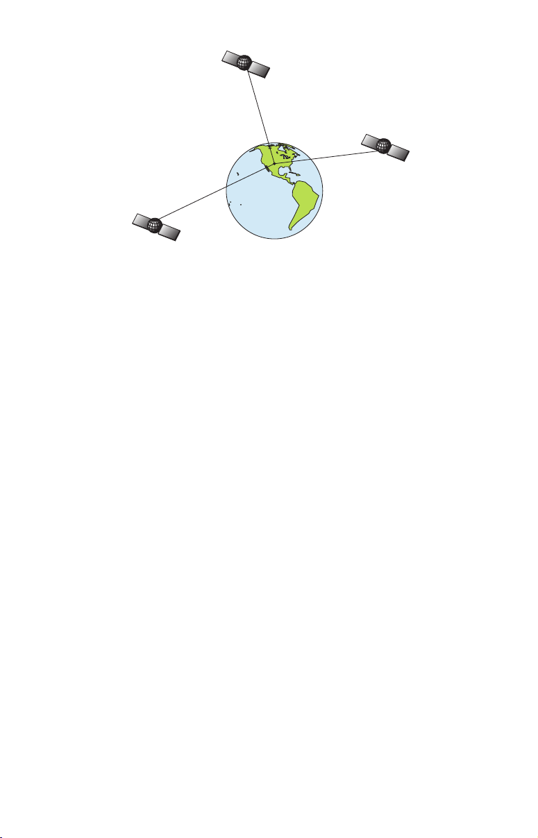
A minimum of three satellites are required to determine a 2D fix.
Twenty-four satellites orbit 10,900 nautical miles above the Earth,
passing overhead twice daily. A series of ground stations (with precisely
surveyed locations) controls the satellites and monitors their exact locations in the sky. Each satellite broadcasts a low-power signal that identifies the satellite and its position above the earth. Three of these satellites are spares, unused until needed. The rest virtually guarantee
that at least four satellites are in view nearly anywhere on Earth at all
times.
The system requires signal reception from three satellites in order to
determine a position. This is called a 2D fix. It takes four satellites to
determine both position and elevation (your height above sea level —
also called altitude). This is called a 3D fix.
Remember, the unit must have a clear view of the satellites in order to
receive their signals. Unlike radio or television signals, GPS works at
very high frequencies. These signals can be easily blocked by trees,
buildings, an automobile roof, even your body.
Like most GPS receivers, this unit doesn’t have a compass or any other
navigation aid built inside. It relies solely on the signals from the satellites to calculate a position. Speed, direction of travel, and distance
are all calculated from position information. Therefore, in order for the
GlobalMap to determine direction of travel, you must be moving and
the faster, the better. This is not to say that it won’t work at walking or
trolling speeds — it will. There will simply be more "wandering" of the
data shown on the display.
GPS is plenty accurate for route navigation, but the U.S. Federal Aviation Administration has special needs for aircraft traffic control that go
beyond basic GPS. The FAA has a plan under way to boost GPS per-
7

formance even further with its Wide Area Augmentation System, or
WAAS. This GPS add-on will include a time control element that will
help airliners fly closer together while avoiding collisions. In addition to
carefully spacing airplanes along travel corridors, WAAS will eventually make instrument landings and takeoffs more accurate as it replaces existing aviation navigation systems.
Non-aviators can use WAAS signals to make their GPS navigation even
more accurate. Your unit receives both GPS and WAAS signals. However, WAAS has some limits you should know about.
First, the U.S. government has not completed construction of the WAAS
system, so it is not yet fully operational. The ground stations are in
place, but only a few of the needed WAAS satellites have been launched.
WAAS can boost the accuracy of land GPS navigation, but the system is
designed for aircraft. The satellites are in a fixed orbit around the
Equator, so they appear very low in the sky to someone on the ground
in North America. Aircraft and vessels on open water can get consistently good WAAS reception, but terrain, foliage or even large man-made
structures frequently block the WAAS signal from ground receivers.
You'll find that using your GPS receiver is both easy and amazingly
accurate. It’s easily the most accurate method of electronic navigation
available to the general public today. Remember, however, that this
receiver is only a tool. Always have another method of navigation available, such as a map or chart and a compass.
Also remember that this unit will always show navigation information
in the shortest line from your present position to a waypoint, regardless
of terrain! It only calculates position, it can’t know what’s between you
and your destination, for example. It’s up to you to safely navigate
around obstacles, no matter how you’re using this product.
How to use this manual: typographical conventions
Many instructions are listed as numbered steps. The keypad and arrow
"keystrokes" appear as boldface type. So, if you're in a real hurry (or
just need a reminder), you can skim the instructions and pick out what
menu command to use by finding the boldface command text. The following paragraphs explain how to interpret the text formatting for
those commands and other instructions:
Arrow Keys
The arrow keys control the movement of dotted cross-hair lines on your
mapping screen called the cursor. The arrow keys help you move
8

around the menus so you can execute different commands. They are
represented by symbols like these, which denote the down arrow key,
the up arrow, the left arrow and the right arrow:
↓ ↑ ← →.
Keyboard
The other keys perform a variety of functions. When the text refers to a
key to press, the key is shown in bold, sans serif type. For example, the
"Enter/Icons" key is shown as
MENU.
ENT and the "Menu" key is shown as
Menu Commands
A menu command or a menu option will appear in small capital letters,
in a bold sans serif type like this:
ROUTE PLANNING. These indicate that
you are to select this command or option from a menu or take an action
of some kind with the menu item. Text that you may need to enter or
file names you need to select are show in italic type, such as trail name.
Instructions = Menu Sequences
Most functions you perform with this unit are described as a sequence
of key strokes and selecting menu commands. We've written them in a
condensed manner for quick and easy reading.
For example, instructions for navigating a trail would look like this:
1. From the Map Page, press
2. Press
↓ to Trail 1|ENT|→|↓ to NAVIGATE|ENT.
MENU|MENU|↓ to MY TRAILS|ENT.
3. You are asked to wait while it converts the trail into a route.
4. The wait message disappears and the GlobalMap begins
showing navigation information along the trail. Now, begin
moving and follow your GlobalMap.
Translated into complete English, step 1 above would mean: "Start on
the Map Page. Press the Menu key twice. Next, repeatedly press (or
press and hold) the down arrow key to scroll down the menu and select
(highlight) the My Trails menu command. Finally, press the Enter key."
Step 2 would mean: "Press the down arrow key repeatedly to scroll to
the trail named Trail 1, and press Enter. Next, press the right arrow
key and then the down arrow key to highlight the Navigate command,
then press Enter."
NOTE
There is a slight difference in menu structure between the GlobalMap 5500C and GlobalMap 4900M. The differences are minimal,
but some of the screenshots in this manual may not perfectly match
9

some of your unit's menus. Most notably, the GlobalMap 5500C has
the transparency feature and the GlobalMap 4900M does not.
10

Section 2:
Installation & Accessories
Preparations
You can install the GPS system in some other order if you prefer, but
we recommend this installation sequence:
Caution:
You should read over this entire installation section before drilling any holes in your vehicle or vessel!
1. Determine the approximate location for the GPS unit, so you can
plan how and where to route the cables for the antenna and power.
This will help you make sure you have enough cable length for the desired configuration.
2. Determine the approximate location for the GPS antenna module
and its cable route.
3. Determine the location of your battery or other power connection,
along with the power cable route.
4. Install the GPS antenna and route the antenna cable to the GPS
unit.
5. Install the power cable and route it to the GPS unit.
6. Mount the GPS unit.
GPS Antenna/Receiver Module
The unit packages include the LGC-2000 GPS module. This device contains the unit's external antenna and receiver for GPS and WAAS signals. The antenna/receiver module comes with a 25-foot Y-adapter extension cable. This module can be mounted on a flat surface or pole, or
an optional magnet is available for temporary mounting on any ferrous
surface.
LGC-2000 Module, bottom view (left) and top view (right).
11
You need to select an antenna installation location that has a clear, unobstructed view of the sky. After the module is installed, connect it to the
unit. The LGC-2000 can communicate with your GPS unit either directly
(using the supplied extension cable) or through a NMEA 2000
network.
NOTE
See the module’s instruction sheet, publication part number 9880147-981, for complete installation instructions.
In an automobile, you may achieve good results by simply placing the
external antenna on the top of the dash, at the base of the windshield. A
piece of the rubber non-skid shelf liner material available in recreational
vehicle supply stores will help hold the antenna in place. This may not
work well if you have a cab-over design pickup truck camper or motor
home. If dashboard reception is poor, simply relocate the antenna module elsewhere on the vehicle for a clearer view of the sky.
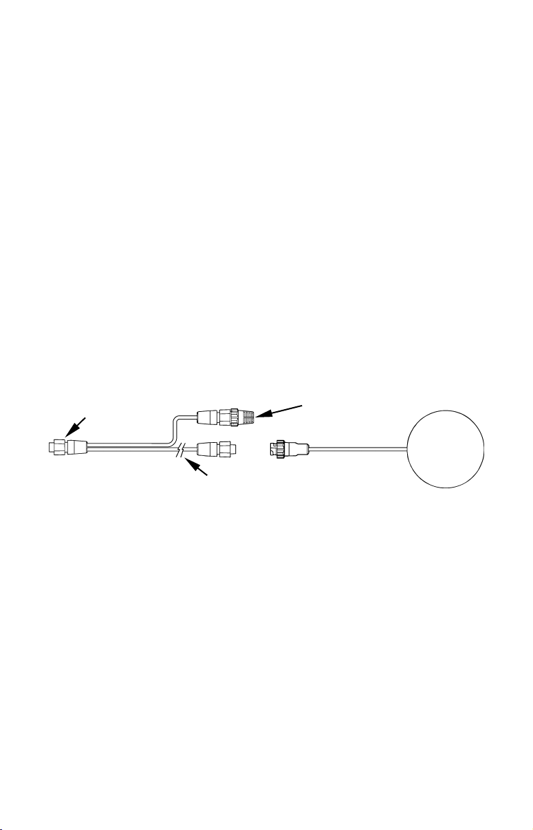
Connecting Directly to the Unit
After the module is installed, attach it to the end of the Y-adapter extension cable as shown in the following diagram. To connect it to the
unit, insert the extension cable's splitter plug into the Network socket
on the back of the unit and your system is ready to use.
60-ohm
terminator
LGC-2000
To unit
Splitter plug
25' Y-adapter
extension cable
LGC-2000 direct connection to GPS unit.
NOTE:
The extension cable’s shorter branch will have a 60-ohm terminator attached to it. Do not remove this terminator. When you're not connecting to a NMEA 2000 buss, you must leave the terminator connected to this socket for your antenna/receiver to function correctly.
Connecting to a NMEA 2000 Network
The LGC-2000 can be connected to a NMEA 2000 buss, providing GPS
information to any Lowrance GPS units attached to the buss. Contact LEI
Extras (look inside back cover for accessory ordering information) for a
NMEA 2000 buss adapter cable if you would like to do this.
There are two ways to connect the antenna to a NMEA 2000 network
port. One method (shown in the following image) is to use the extension
cable's Y-adapter to connect both the antenna and the unit to the same
network port. To do this, simply remove the 60-ohm terminator shown in
12
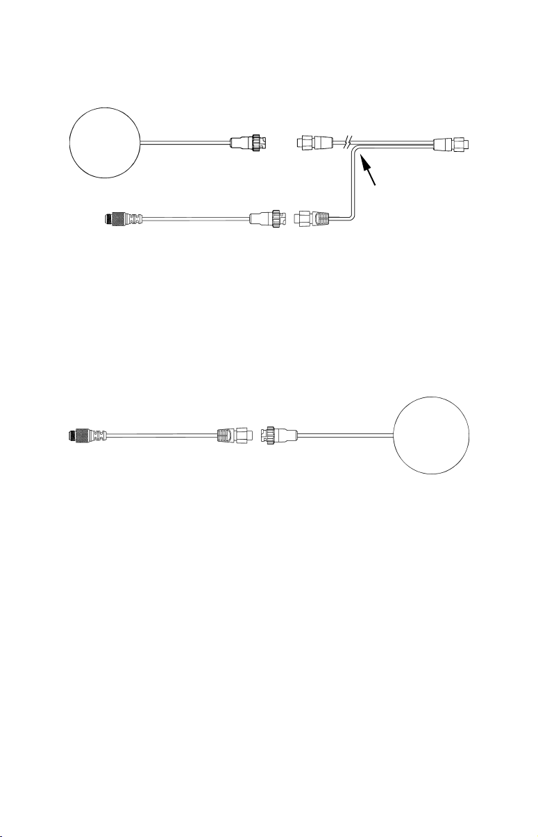
the previous image and attach the NMEA 2000 buss adapter cable to the
shorter branch of the extension cable's Y-adapter. Connect the NMEA
2000 buss adapter cable's other end to an available network port.
LGC-2000
25' Y-adapter
extension cable
To NMEA 2000
network port
LGC-2000 and GPS unit connection to NMEA 2000 buss.
To unit
You can also attach the antenna to a remote port on the network, and
pass position information along the network. To do this, simply attach the
LGC-2000's connector to one end of the buss adapter cable and attach the
other to an available port on the NMEA 2000 buss, as shown in the following image. (You will have to use a similar adapter cable to connect the
GPS unit to the NMEA buss as described later in this section.)
To NMEA 2000
network port
LGC-2000
LGC-2000 remote connection to NMEA 2000 buss.
NOTE:
An existing operational NMEA 2000 buss will already have terminators in place and will already be powered. If you're connecting to such a
network, you won't need the terminators or extension cable provided.
Do not add terminators or power to a functional NMEA 2000 buss!
When the LGC-2000 is connected to the unit (directly or indirectly), it
will begin providing GPS signal information.
Power Connections
Your unit comes with a power/data cable that splits into three ends,
each with several exposed wires (shown in the following figure). The
end with 4 wires (blue, yellow, orange and shield) is a Data cable that
connects to a NMEA 0183 interface. The end with three wires (red,
black and shield) is a power cable that connects to a NMEA-2000 buss.
The thicker three-wire cable (red, black and white) is the Power Supply
for your unit (and optional external speaker connection for some units).
13
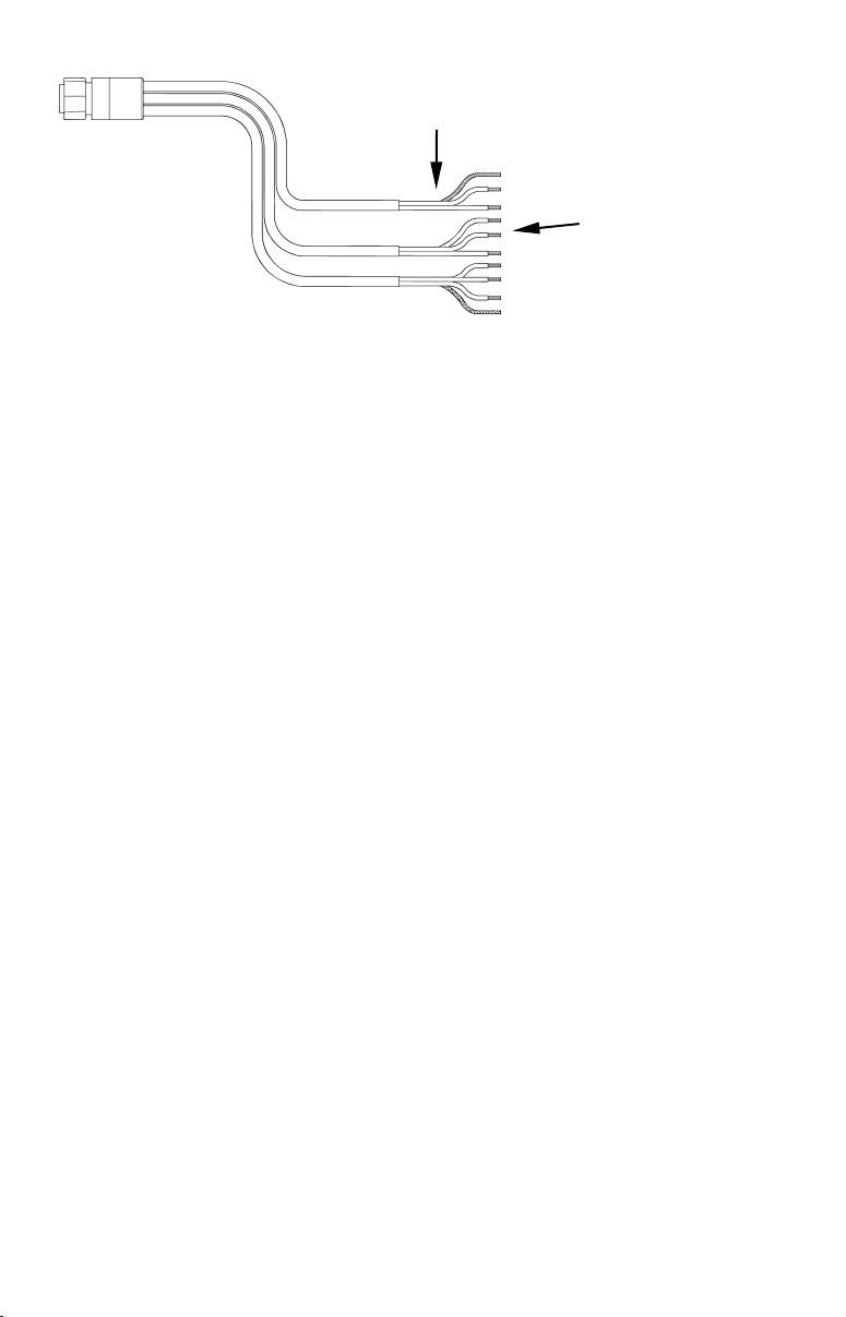
Power Supply wires:
red, black and white
To unit
NMEA-2000 Power wires:
red, black and shield
Data Cable wires: blue,
yellow, orange and shield
The Power/Data cable for this unit.
Depending on your configuration, you may not use all of these wires.
The following segments include instructions for installing all the wires
that you will use with this unit.
CAUTION:
All of the wires in the power/data cable have bare ends for easier
installation. The bare ends on any unused wires could cause an
electrical short if left exposed. To prevent this, you should cover the
individual wire ends — either by capping them with wire nuts or
wrapping them with electrical tape. (You should cut off the bare
wire before taping off the ends.)
Powering a NMEA-2000 Buss
(NMEA-2000 Power cable)
A NMEA-2000 buss must be connected to a power source to operate. If
you have a pre-existing NMEA-2000 installation, it may already be
connected to another power source. If your NMEA-2000 buss is already
powered, you can ignore the NMEA-2000 Power cable. Never attach
two power sources to a single NMEA-2000 buss.
If you do need to power your NMEA-2000 buss, attach the NMEA-2000
Power cable to your boat's battery just as indicated in the following
segment for connecting your unit's Power Supply cable. The NMEA2000 Power cable's red wire should be attached (with provided 3-amp
fuse) to the boat battery's positive terminal, and the NMEA-2000 Power
cable's black and shield wires should both be attached to the battery's
negative terminal.
NOTE:
If the NMEA-2000 buss draws power directly from the boat's battery,
the LGC-2000 will remain on (drawing power) all the time. The LGC2000's current draw is very small and shouldn't decrease the boat's
storage battery life, but if this small draw is a concern, you can install a switch between the NMEA-2000 buss and the battery.
14

Powering Your Unit
(Power Supply cable – red and black wires)
The unit works from a 12-volt battery system. For the best results, attach the power cable directly to the battery. You can attach the power
cable to an accessory or power buss, however you may have problems
with electrical interference. Therefore, it's safer to go ahead and attach
the power cable directly to the battery.
CAUTION:
When using the unit in a saltwater environment, we strongly recommend that you shut off the power supply to the power cable when
the unit is not in use. When the unit is turned off but still connected
to a power supply, electrolysis can occur in the power cable plug.
This may result in corrosion of the plug body along with the electrical contacts in the cable and the unit's power socket.
In saltwater environments we recommend you connect the power
cable to the auxiliary power switch included in most boat designs.
If that results in electrical interference, or if such a switch is not
available, we recommend connecting direct to the battery and installing an inline switch. This will let you shut off power to the
power cable when the unit is not in use. When you are not using
the unit, you should always shut off power to the power cable, especially when the power cable is disconnected from the unit.
If possible, keep the power cable away from other boat wiring, especially
the engine's wires. This will provide the best isolation from electrical
noise. If the cable is not long enough, splice #18 gauge wire onto it. The
power cable has two wires, red and black. Red is the positive lead, black
is negative or ground. (There is also a white wire to power an optional
external speaker for some units.) Make sure to attach the in-line fuse
holder to the red lead as close to the power source as possible.
For example, if you have to extend the power cable to the battery or
power buss, attach one end of the fuse holder directly to the battery or
power buss. This will protect both the unit and the power cable in the
event of a short. It uses a 3-amp fuse.
15
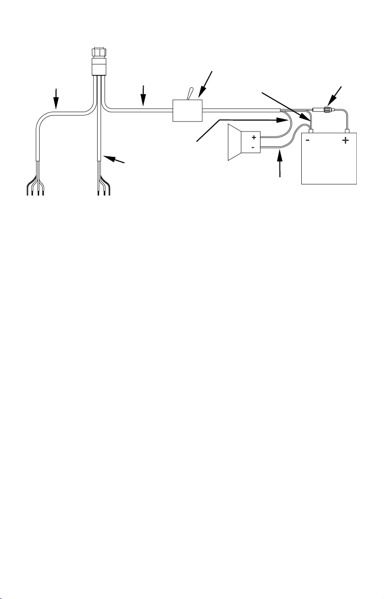
To unit
battery.
NMEA 0183
Data cable
(four wires)
To power a
NMEA-2000
buss, also
connect
NMEA-2000
Power cable
to the boat's
Power and optional speaker connections for the GlobalMap 5500C and
Unit power
supply cable
White speaker wire
NMEA 2000
Power cable
4900M GPS units.
Optional power off
switch for saltwater
installations
Black wire
Speaker
Black speaker wire
Red wire with
3 amp fuse
12 volt
battery
NOTE:
If you're powering a NMEA 2000 buss, you will attach both the
NMEA 2000 Power cable and the unit's Power Supply cable to the
boat's battery. You must also attach both the power cables to the
battery when you are only connecting the GPS module to the unit
with the Y-adapter cable. To attach the NMEA 2000 Power cable,
connect the red wire to battery's + and black and shield wires to
battery's –.
WARNING:
This product must be independently fused with the enclosed 3-amp fuse (or equivalent), even if you connect to
a fused accessory or power buss.
If a malfunction happens inside the unit, extensive damage can occur if the enclosed fuse is not used. As with all
electrical devices, this unit could be damaged to a point
that it is unrepairable and could even cause harm to the
user when not properly fused.
CAUTION:
Do not use this product without a 3-amp fuse wired into the power
cable! Failure to use a 3-amp fuse will void your warranty.
This unit has reverse polarity protection. No damage will occur if the
power wires are reversed. However, the unit will not work until the
wires are attached correctly.
External Speaker
Your unit can play sounds to an external speaker. This feature can be
convenient any time you are away from the unit — especially in a
16

larger boat — but still want to hear its alarms. You might install a
small speaker at the stern of your boat so you won't miss a dangerous
Shallow Alarm while fishing, or put one in your galley so you can hear
the GPS Arrival Alarm.
You can purchase an external speaker and the wire to connect it at
your nearest audio or marine electronics store. You will need to buy
marine-grade 18 gauge stranded wire. Buy enough of one color (we suggest white) to run from the unit's Power/Data cable to the speaker. Buy
enough of another color (we suggest black) to run from the speaker to
the battery or fuse box.
The unit is designed to work with most speakers, but make sure you
buy one that meets these minimum requirements:
• Minimum 8-ohm resistance
• Minimum 5-watt power
In your vessel or vehicle, mount the speaker wherever you want to hear
your unit's sounds. (Follow the speaker's installation instructions).
Next, connect the speaker to your unit as shown in the preceding figure.
The speaker should have either two terminals or two exposed wires: a
positive (+) and a negative (–) ground. Your unit's external audio output is the white wire in the unit power supply cable. Connect this wire
to the speaker's positive (+) wire or terminal with white 18 gauge wire.
Connect the speaker's negative (–) ground wire or terminal to the negative (–) terminal on your battery or fuse box with black 18 gauge wire.
The unit should automatically begin to play any active sounds through
the attached speaker.
NMEA 2000 Cable Connections
NMEA 2000 is a new buss network specifically designed for boats. This is
a very young industry standard and, at the time of printing, a few boats
being built now have a NMEA 2000 buss installed. Over the next few
years, however, NMEA 2000 will become much more common. To help
you get the most out of this technology, your Lowrance unit is designed
to work with a NMEA 2000 network as soon as it becomes available.
Connecting to a NMEA 2000 Network
Your unit can be connected to a NMEA 2000 buss, receiving sensor information from any Lowrance units attached to the buss. Contact LEI Extras
(look inside back cover for accessory ordering information) for a NMEA
2000 buss adapter cable if you would like to do this. You can connect both
the unit and antenna module through the antenna's extension cable (as
described earlier), or you can connect the unit directly to a network port.
17
To do so, attach the adapter cable's manual locking collar connector to the
Yellow (Transmit)
Network port on the back of the GPS unit and attach the other end to an
available port on the NMEA 2000 buss, as shown in the following figure.
To NMEA 2000
network port
Lowrance unit direct connection to NMEA 2000 buss.
To unit's
Network
socket
As soon as the unit is connected to the network, it will begin receiving
shared information. Please note the buss must be powered to operate. (See
instructions in this section for more on powering NMEA 2000 buss.)
NMEA 0183 Cable Connections
NMEA 0183 is a standard communications format for marine electronic
equipment. For example, an autopilot can connect to the NMEA interface on the GlobalMap 5500C/4900M and receive positioning information. The GlobalMap can exchange information with any device that
transmits or receives NMEA 0183 data.
See the following diagram for general wiring connections. Read your
other product’s owner’s manual for more wiring information.
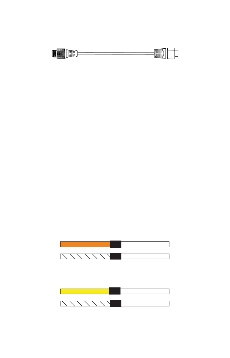
NMEA 0183 Wiring Diagrams
(Data cable)
To exchange NMEA 0183 data, this unit has one NMEA 0183 version
2.0 communication port. Com port one (Com-1) can be used to receive
NMEA format GPS data. The com port can also transmit NMEA format
GPS data to another device.
The four wires for the com port are combined with the Power Supply cable
and NMEA 2000 Power cable to form the power/data cable (shown earlier).
Com-1 uses the yellow wire to transmit, the orange wire to receive and the
shield wire for signal ground. Your unit does not use the blue wire.
Com-1
To unit
Orange (Receive)
Shield (Ground)
NMEA Transmit
Ground
To Other
GPS Receiver
Com-1
To unit
Com-1 wiring to receive NMEA position information
from some other GPS receiver.
NMEA Receive
Shield (Ground)
Com-1 wiring to transmit NMEA position information
to another NMEA-compatible device.
Ground
18
To Other
Device
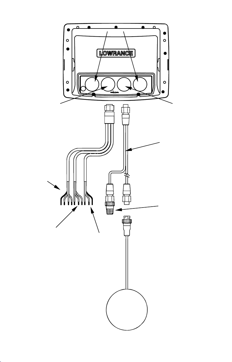
Power/Data
Blank
NMEA 0183
Data cable
(four wires)
NMEA
2000
Power
cable
Network
25' Y-adapter
extension cable
60-ohm
terminator
Power
Supply
wires
LGC 2000
GPS Module
19
Mounting the Unit: Bracket, In-Dash or Portable
You can install the GlobalMap on the top of a dash with the supplied
gimbal bracket. It can also be installed in the dash or mounted on a
portable power supply.
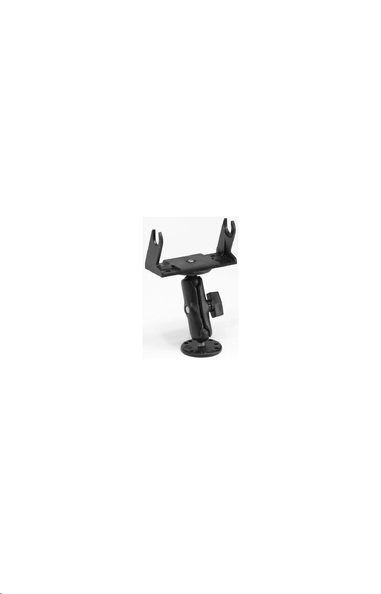
If you use the supplied bracket, you may be interested in the optional
R-A-M
bracket mounting system. This converts the unit's gimbal
bracket to a swivel mount, which can be used on the dash or overhead
mounting positions. Installation instructions are supplied with the
R-A-M mounting kits. R-A-M offers permanent mounts and temporary
mounts suitable for many vehicle types. See your Eagle dealer or visit
the LEI web site (
www.lei-extras.com) for the latest options; accessory
ordering information is on the inside back cover of this manual. For
a complete look at the many mounting options, visit the RAM web site
at
www.ram-mount.com.
Optional R-A-M mounting system.
Bracket Installation
Mount the GlobalMap in any convenient location, provided there is clearance behind the unit when it's tilted for the best viewing angle. You should
also make sure there is enough room behind the GlobalMap to attach the
power and GPS antenna/receiver module cables. (A drawing on the next
page shows the dimensions of a gimbal-mounted GlobalMap.)
Holes in the bracket's base allow wood screw or through-bolt mounting.
You may need to place a piece of plywood on the back side of thin fiberglass panels to reinforce the panel and secure the mounting hardware.
20
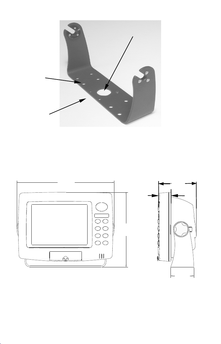
hole
Cable hole
Screw
mounting
Front
Install the gimbal bracket. Place the bracket so the arms slope toward
the front of your unit.
Once a location is determined, use the bracket as a template and mark
the mounting holes and the hole for the cables. Drill a 1-inch (25.4 mm)
hole in the dash for the power, transducer and antenna cables. Screw
the bracket to the mounting surface.
244
[9.58]
37.1
[1.37]
185
[7.34]
Millimeter
[Inch]
Front view (left) and side view (right) showing dimensions of the GPS
unit when mounted on gimbal bracket.
To pass all connectors through the 1" hole, first pass the transducer
connector up through the hole from under the dash, followed by the an-
21
94
[3.61]
56.9
[2.24]
tenna connector and any accessory cables. Next, pass the power cable's
bare-wire end down though the hole from the top.
If you wish, you can fill in the hole around the cables with a good marine caulking compound. No matter what type of installation you prefer, be sure to leave enough slack in the cables to allow tilting or swiveling the unit.
Attach the unit to the gimbal bracket using the supplied gimbal knobs
and washers. Attach the cables and the unit is ready to use.
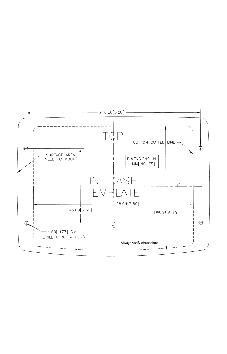
In-Dash Installation
You can mount the unit in the dash with an optional FM-3 In-Dash
Adapter Kit. The kit includes mounting hardware and a template for
cutting the hole.
In-dash mounting template for this unit, showing dimensions.
NOTE: The figure above is not printed to scale.
Portable Installation
Like many Lowrance products, the GlobalMap is capable of portable
operation by using an optional portable power pack. The power pack
and the magnet-equipped antenna module expand the uses for your
GPS unit. The portable power pack makes it easy to transfer your unit
from a boat to a car, recreational vehicle, airplane or other vehicle
without drilling and mounting a second bracket. You can use your unit
22
in your own car or boat, then take it along when riding in a friend's vehicle that's not equipped with GPS.
The portable power pack includes a sealed, rechargeable battery.
MMC or SDC Memory Card Installation
Your unit uses MultiMedia Cards to store information, such as custom
maps, waypoints, trails and other GPS data. The unit can also use Secure Digital Cards (SD card or SDC) to store data. The unit can use up
to two cards; an MMC and an SDC can be used at the same time.
NOTE:
Throughout this manual, we will use the term MMC, but just remember your unit can use an MMC or SDC to store data.
Both of these solid-state flash memory devices are about the size of a
postage stamp. A SD card is slightly thicker than a MMC. MMCs are
available in storage capacities of 8 MB, 16 MB, 32 MB, 64 MB and
higher. SD cards are available in capacities of 8 MB, 16 MB, 32 MB, 64
MB, 128 MB, 256 MB and 1 GB.
Additional MMC cards are available from LEI Extras; see ordering information inside the back cover of this manual. MMCs and SD cards
are also available at many camera and consumer electronics stores.
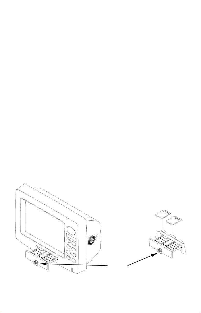
The MMC drawer is located on the front of the case. To install an
MMC, twist the drawer retainer counter-clockwise and pull. The
drawer will come out of the unit. Place the MMC in the drawer face
down (see following figures.)
Insert cards face down
Drawer
retainer
Memory card drawer on the GlobalMap 5500C and 4900M.
23
Slide the drawer back into the unit and twist the retainer clockwise.
The MMC is now ready for use.
Other Accessories
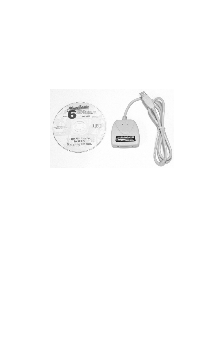
Other accessories include MMC cards, MMC card readers and MapCreate™ 6 custom mapping software for your computer. MMC card readers
are available in USB versions.
If these accessories are not available from your dealer, see the accessory ordering information on the inside back cover of this manual.
MapCreate™ 6 CD-ROM, left; MMC card reader for USB ports, right.
Now that you have your GlobalMap installed, move on to Section 3, Basic GPS Operations. There, we'll present a series of step-by-step tutori-
als to teach you the basics of GPS navigation.
Face Cover
Your unit comes with a white protective cover that snaps on and off the
front of the unit. This cover is intended for use when your unit and the
vehicle it's mounted in are idle.
WARNING:
When the unit is mounted in an unprotected area, such
as an open boat cockpit, the protective face cover must
be removed when the vehicle is moving at high speed.
This includes towing a boat on a trailer at highway
speeds. Otherwise, wind blast can pop off the cover.
24
 Loading...