

Page 1

INSTALLATION & INSTRUCTION
MANUAL
SP3000
FLOW COMPUTER
DOC#: MN-3000.DOC
Page 2

2
- WARNING -
This instrument contains electronic components that are susceptible to damage by static electricity.
Please observe the following handling procedures during the removal, installation, or handling of the
internal circuit boards or devices.
HANDLING PROCEDURES
1. Power to unit must be removed.
2. Personnel must be grounded, via wrist strap or other safe, suitable means, before any printed
circuit board or other internal device is installed, removed, or adjusted.
3. Printed circuit boards must be transported in a conductive bag or other conductive container.
Boards must not be removed from protective enclosure until the immediate time of installation.
Removed boards must be placed immediately in protective container for transport, storage, or
return to factory.
COMMENTS
This instrument is not unique in its content of EDS (electrostatic discharge) sensitive components. Most
modern electrical designs contain components that utilize metal oxide technology (NMOS, CMOS, etc.).
Experience has proven that even small amounts of static electricity can damage or destroy these devices.
Damaged components, even though they appear to function properly, exhibit early failure.
*** SPONSLER, INC. STRONLY RECOMMENDS THOROUGH UNDERSTANDING AND REVIEW OF
THIS MANUAL PRIOR TO INSTALLATION.
Page 3

3
TABLE OF CONTENTS
INTRODUCTION 4
1.1 GENERAL DESCRIPTION 4
1.2 FEATURES 4
1.3 APPLICATION 5
1.4 GENERAL SPECIFICATIONS 6
1.5 INPUT S PEC I F ICATIONS 6
1.51 ANALOG INPUTS 6
1.52 RTD TEMPERATURE INPUTS 7
1.53 DIGITAL FLOW INPUT 7
1.6 OUTPUT SPECIFICATIONS 8
1.61 ANALOG OUTPUT 8
1.62 DIGITAL FLOW PULSE OUTPUT 8
1.63 RELAY OUTPUTS 9
1.64 AUXILIARY POWER OUTPUT 9
1.7 RS-232 COMMUNICATIONS PORT 9
1.8 DATA DISPLAY AND KE YPAD 10
INSTALLATION 10
2.1 MOUNTING THE INSTRUMENT 10
2.2 CONNECTING INPUTS AND OUTPUTS 11
PROGRAMMING CONSIDERATIONS 18
3.1 FRONT PANEL KEYPAD OPERATION 19
3.2 SETTING COMPUTATIONS 20
3.3 SELECTING THE ENGINEERING UNITS 22
3.4 SETTING THE HARDWARE 22
3.5 SETTING THE VARIABLES 24
3.51 SETTING THE PRESSURE VARIABLES 24
3.52 SETTING THE TEMPERATURE VARIABLES 25
3.53 SETTI NG T H E FLOW VARIABLES 26
3.54 FLOWCHART: DIGITAL PULSE -LINEAR 26
3.55 FLOWCHART: DIGITAL PULSE - SIXTEEN POINT 27
3.551 DIGITAL PULSE – SIXTEEN POINT PROGRAMMING 28
3.6 ANALOG LINEAR INPUT SETTINGS
3.7 ANALOG ORIFICE/PITOT INPUT SETTINGS 33
3.8 SETTING THE FLOW OUTPUT VARIABLES 34
CLEARING THE TOTALIZER: RESETTING THE TOTALIZER TO 0.000 34
CHECKING THE ALARM: VIEW THE MOST RECENT ALARM CONDITION 36
REAL TIME CLOCK 39
RUNNING MODE 40
8.1 SHOW DATA 41
8.2 PRINT LIST (RS-232 OPTION) 42
8.3 PRINT SYSTEM SETUP (RS-232 OPTION) 42
8.4 EXAMINE HARDWARE 43
8.5 EXAMINE COMPUTATIONS 43
8.6 EXAMINE VARIABLES 43
8.7 CHECK ALARM 44
8.8 LOCK/UNLOCK 45
PRINCIPLES OF OPERATION 46
9.1 GENERAL 46
9.2 TEMPERATURE CALCULATIONS 46
9.3 PRESSURE CALCULATIONS 46
9.4 FLOW CALCULATIONS 46
Appendix i 48
Appendix ii 51
Appendix iii 51
Appendix iv 52
Appendix v Troubleshooting Guide 52
RS-232 OPERATING INSTRUCTIONS 53
3.552 PROGRAMMING EXAMPLE 29 31
3.61 ANALOG 16 POINT INPUT SETTINGS 32
8.1.1 DISPLAY DATA SE TUP 41
Page 4

4
MODEL SP3000 MASS FLOW COMPUTER
INTRODUCTION
1.1 GENERAL DESCRIPTION
The Model SP3000 is a microprocessor based instrument designed to measure and compensate
flow in an industrial environment. Three inputs - temperature, pressure, and flow – are provided
for calculating the flow at standard conditions. Special signal conditioning circuitry is included to
allow direct connection of 2, 3, or 4 wire platinum Resistance Temperature Detectors (RTDs),
voltage inputs or current loops. A high speed digital input is provided for interfacing with the
meter mounted SP714 Pulse Amplifier. A 32 terminal strip on the rear panel provides easy
connection to the instrument.
The Model SP3000 is powered by 50 or 60 Hz, 110 or 220 VAC, switch selectable, or can be
ordered for 24 VDC power.
The Model SP3000 is designed to provide continuous, on-line, compensation for true flowrate
from volumetric flow transducers. All volumetric, mass, or heat flow calculations are taken with
permission from the Flow Measurement Engineering Handbook written by R.W. Miller. Steam
(100% quality, saturated, or superheated to 850
Steam tables.
Operator interface is through a 16 key keypad and a 2 line by 20 character liquid crystal display.
(The Model SP3000 may also be set up entirely through the optional RS-232 port). Range
selection, input filtering characteristics, scaling factors, etc. are selected through the front panel
keypad or RS-232 interface. There is no need to disassemble the unit or set any dip switches.
Scaled digital and 4-20mA analog current outputs, that represent compensated flow, are standard
for use in remote monitoring of flow. Two form C relays provide isolated flow or
temperature/pressure alarm outputs.
There is a single precision voltage reference in the unit used for all analog measurements. A
single multi-turn potentiometer is provided for factory calibration. No field adjustments are
necessary.
1.2 FEATURES
The Model SP3000 is designed to provide accurate and low cost compensated flow
measurement for industrial applications. The instrument can be set up to display volumetric,
mass, or heat flow, as well as totalized flow, with an overall accuracy of 0.25%.
Fully programmable from the front keypad, the microprocessor-based Model SP3000 Flow
Computer provides the operator with prompts to set up the operating parameters of the
instrument.
The Flow Computer offers the following features:
* Front Panel 16 key programming keypad
* 2 line 20 character liquid crystal display
* Compensates gas & steam flowrates for
temperature and pressure
* Compensates liquid flowrates for temperature
* Direct input of 100 ohms RTD
* Can display flow and heat flowrates and totals
* Scaleable 5V output pulse
* Analog output of 4-20mA proportional to
compensated flowrate
* 12 bit input resolution for A/D conversion
o
F) computations are based on the 1967 ASME
* Non-volatile RAM memory
* Self diagnostics of instrument
* Supervisory lockout of keypad
* Provides 24 VDC excitation at 100mA
* English and metric engineering units selectable via
front keypad
* Flowrate and temperature/pressure alarms via two
SPDT relays
* Real time clock and calendar (not battery backed)
* Optional 16 point linearization of input signal
* Optional RS-232 communications
Page 5
5
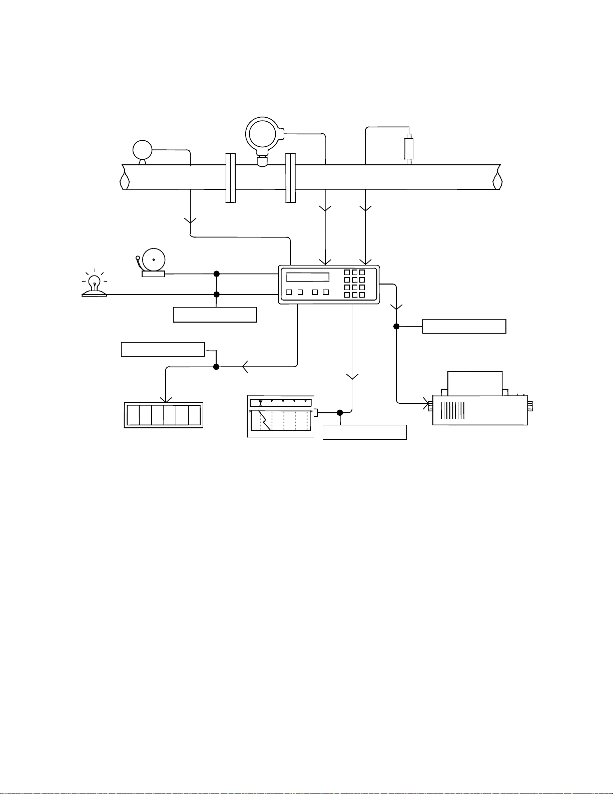
1.3 APPLICATION
P
Pulse Output
RS232 Output
4-20mA Output
TRANSDUCER
AMPLIFIER
100 OHMS RTD
FLOWMETER
COMPUTER
TOTALIZER
PRINTER
PRESSURE
SP714 PULSE
SP3000
MASS FLOW
BELL
LIGHT
Alarm Outputs
1 2 3 4 5 6
REMOTE
* Pressure Transducer sends 4-20mA signal to Model SP3000
* 100 ohms RTD direct hook-up to Model SP3000
* Meter Mounted SP714 Pulse Amplifier sends digital signal to Model SP3000
* Model SP3000 calculates flow and sends out signals
* 5V pulse out to remote totalizer in supervisory area
* 4-20mA out to stripchart recorder tracks trends
* RS-232 out to printer for data logging
* Alarm relays activate bell and/or light as needed
*
Page 6

6
1.4 GENERAL SPECIFICATIONS
1.5 F
12
11
A/D
92 K
Operating Temperature: 32
Storage Temperature: -10
o
to 122o F (0o to 50o C)
o
to 160o F (-32o to 71o C)
Humidity: 0 to 90% Non-Condensing
Front Bezel: NEMA 4X
Case: ABS Plastic
Dimensions: See page 2-1, fig 2-1
Voltage: 115 or 230 VAC +/- 15% (Switch Selectable)
50/60 Hz, 24 VDC +/- 20%
Power Consumption: 10 Watts max.
1.5 INPUT SPECIFICATIONS
The following applies to all inputs in all modes. Inputs are referenced to the signal ground. All ground terminals are
connected internally. The exception is the RTD input which is differential but is referenced to ground.
Transient Protection: 100V 5nsec
Note: In the event of the specified fault conditions, unit may temporarily malfunction, but no permanent
damage will occur.
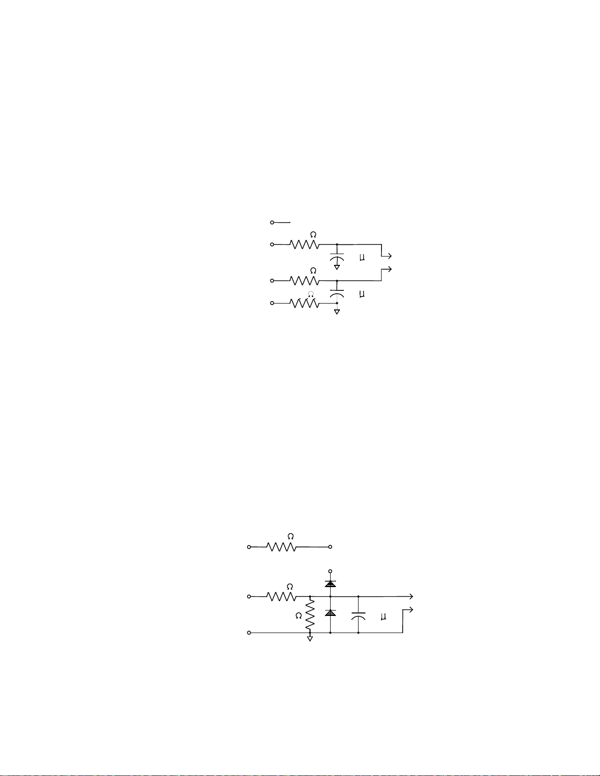
1.51 ANALOG INPUTS
Temperature, Pressure, and Flow (1 each)
* Current Input
Input Impedance: 100 ohms
Range: 0-20mA, 4-20mA
Maximum sustained input voltage: 5VDC (Fault Condition)
100
22.9 K
A/D
1.5 F
13
14
Typical Current Input Schematic:
* Voltage Input
Input Impedance: 100K ohms
Range: 0-5V, 0-10V
Typical Voltage Input Schematic:
Page 7
7
1.52 RTD TEMPERATURE INPUTS
2.2 VDC @ 2mA
1.5 F
1.5 F
20K
20K
100K
1.5 F
5 VDC
@ 0.9 mA
5.6 K
39 K
100 K
+5 VDC
+5 VDC
16
1718COUNTER
Compatible RTD type: 100 ohms Platinum
(a=0.00385; DIN 43-760 Calibration)
Configuration: 2, 3, or 4 wire
Excitation Current: 2mA typical
Max Fault Current: 15mA
Max Voltage on Sense Inputs: 50 VDC
Rejection of 50-60Hz signal: 40 dB (minimum)
(Automatically based on line frequency)
Raw Accuracy: 0.2% FS RTI
Temperature Range: -323.5
(-197.5
Typical RTD Schematic:
o
to +1378.7o F
1
2
3
4
o
to +748.1o C)
~
A/D
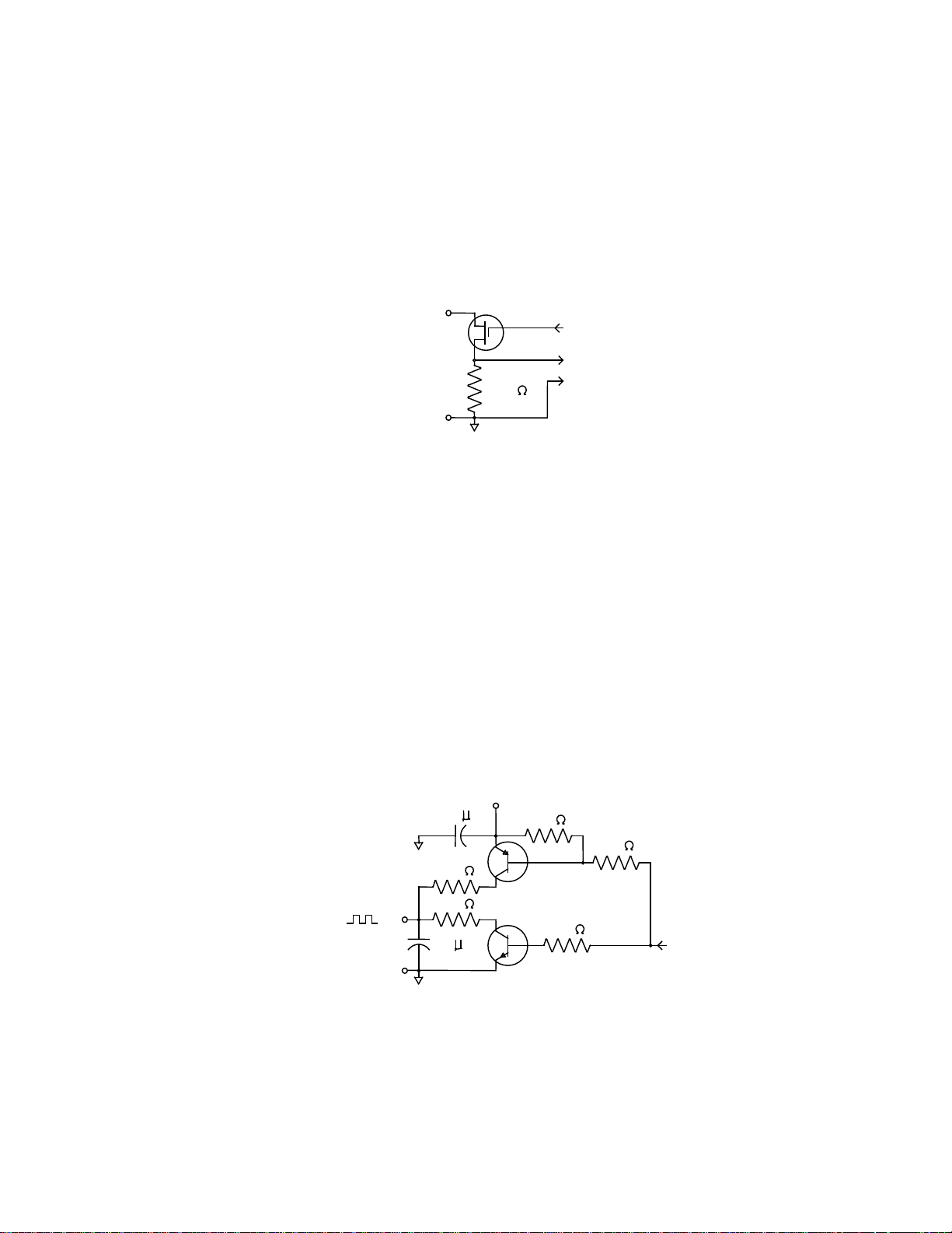
1.53 DIGITAL FLOW INPUT
Range: 3-30 VD C Pu ls e
Type: Dry contact, opto-isolated or
voltage source
Max Input Frequency: 40kHz
Min. Pulse Width: 10µsec (with 40kHz filter)
Thresholds: OFF is less than 2.0V/ ON is
greater than 2.5V
Input Impedance: Less than 30K ohms to ground
Excitation Voltage: 5VDC through 5.6K ohms resistor
Min. Frequency to maintain rate display: 1 Hz
Note: Totalizer counts all pulses down to 0 Hz
Typical Digital Pulse Input & Schematic:
Page 8
8
1.6 OUTPUT SPECIFICATIONS
~
.001 F
1.5 F
TTL 5 VDC
@ 21mA
+ 5 VDC
CPU
3.3 K
3.3 K
3.3 K
220
220
21
20
1.61 ANALOG OUTPUT
Number: 1
Range: 4-20mA DC, sink only
Compliance Voltage Range: 3.0-24 VDC
Load Type: Non-Inductive
Accuracy: +/- 100 µA
Update Rate: 1 Hz
Analog Output Schematic:
1.62 DIGITAL FLOW PULSE OUTPUT
This output is intended to drive a counter with a minimum input impedance of 1000 ohms. It is also
compatible with TTL, LSTTL, and 5V CMOS logic inputs. It is slew rate limited to help prevent RFI.
Number: 1
Output High Voltage No Load: 4.5 Volts min.
4.0mA source: 4.5 Volts min.
Output Low Voltage No Load: 0.2 Volts max.
4.0mA sink: 1.0 Volts max.
Output Waveform: Symmetric square wave above 1Hz
100msec pulse below 1Hz
Max Output Slew Rate: 27 Volts/µsec
Sustained Fault Voltage for
no permanent damage: 7 Volts
Transient Protection: 1500V 50µsec
Pulse Output Schematic:
19
CPU
A/D
100
18
Page 9

9
1.63 RELAY OUTPUTS
Ground (7)
One relay is provided as a flow alarm and a second is provided for the other alarm conditions.
Each has the following specifications:
Type: Dry contact, Form C
Contac t Rat ing: 10A at 115/230 VAC/28 VDC
Typical Relay Output Schematics:
22
23
24
1.64 AUXILIARY POWER OUTPUT
Voltage: 24 VDC regulated and filtered
Isolation: 230 VAC max
Current: 0 to 100 mA
Protection: Short Circuit Proof
1.7 RS-232 COMMUNICATIONS PORT
(Refer to RS-232 Addendu m supplied with RS-232 option)
Connector: 25 Pin Sub-D
Input Impedance: 3000 ohms to 7000 ohms
Compliance Voltage:
Output: -25 to –5 (Mark); 5 to 25 (Space); Volts
Input: -25 to –3 (Mark); 3 to 25 (Space); Volts
Protection: Short Circuit Proof
Protocol: 8 bits, 1 stop bit
Parity: None (Not Monitored)
Available Baud Rates: 300, 1200, 9600
RS-232 Connector Pin Out:
Printer Busy (11)
Transmit (3)
Recieve (2)
12345678910111213
25
Pins 6, 8, and 20 are jumpered together
Pins 4 and 5 are ju m pered together
24 23
22 212019
18 17
16 15
14
Page 10
10
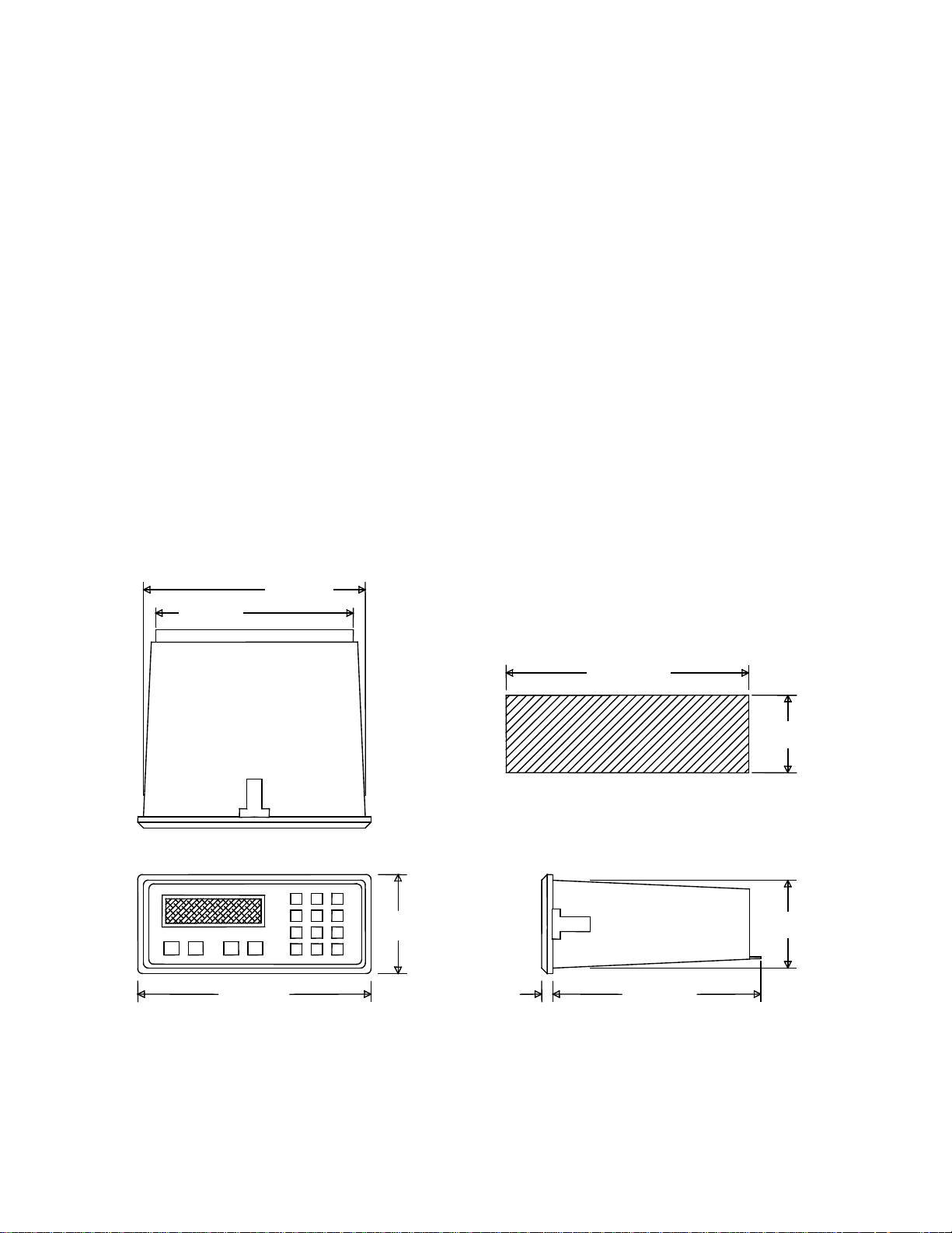
1.8 DATA DISPLAY AND KEYPAD
7.055 (179.2)
2.495 +/- .010
7.365 +/- .010
.525
6.000 (152.4)
2.480
3.305
(207.5)
8.170
Internal 2 line by 20 character dot matrix LCD display. Sealed, 16 key panel featuring numeric keys 0-9,
plus the following keys:
A Advance through menus
B Back up through menus
C Cancel current menu selection
D Decimal point key
ENT General purpose enter or recall data key
CLR Data clear key
INSTALLATION
2.1 MOUNTING THE INSTRUMENT
The Model SP3000 can be mounted in a user panel greater than 0.047” (1.2mm) and less than 0.187”
(4.7mm) thick. Figure 2-1 shows the cutout dimensions, bezel size, and depth needed for the instrument.
Be sure to provide additional space for cabling and connections behind the instrument (approximately 1.0”).
Additionally, all wiring to the back of the instrument should have sufficient service loops to allow for the
easy removal of the instrument from the panel.
Slip the gasket provided over the rear of the instrument case and slide it forward until it engages the inner
surface of the front bezel, slide the instrument into the panel opening. Install the screws provided in the
mounting brackets and insert in the slots located on all four sides of the instrument. Tighten the screws to
firmly secure the bezel and gask et up against the pa nel .
CAUTION: Do not over tighten mounting screw brackets
7.349 (186.7)
(187.0 +/- .25)
(63.4 +/- .25)
PANEL CUTOUT DIMENSIONS
321
654
987
DCBA
C0E
(83.9)
(13.5)
(62.9)
Figure 2-1
Dimensional Layout
Page 11

11
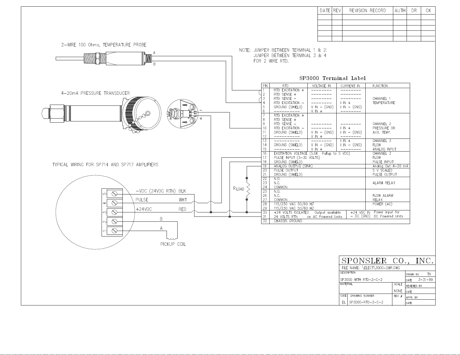
2.2 CONNECTING INPUTS AND OUTPUTS
PIN
RTD
VOLTAGE IN
CURRENT IN
FUNCTION
1
6
RTD EXCITATION +
----------------------------
-------------------------
V IN +
----------------------
----------------------
GROUND (SHIELD)
20
21
PULSE OUTPUT
GROUND (SHIELD)
5 V SCALED
PULSE OUTPUT
24
COMMON
25
N.O.
28
29
115/230 VAC 50/60 HZ
115/230 VAC 50/60 HZ
POWER (AC)
30
31
+24 VOLTS ISOLATED Output available
24 VOLTS RTN on AC Powered Units
+24 VDC IN Power input for
-- DC (GND) DC Powered Units
32
CHASSIS GROUND
Make sure all power is disconnected before making any electrical connections. All connections are
completed at the rear terminal strips as indicated in the external wiring diagram. If cables are in areas with
heavy electrical fields, shielding will be required for noise immunity. One end of the shielding should be
connected to earth ground. Figures 2-2 though 2-9 show the input, output and power wiring locations for
the 32 point terminal block on the back of the instrument.
2
RTD SENSE +
3
RTD SENSE –
4
RTD EXCITATION –
5
GROUND (SHIELD)
7
RTD EXCITATION +
8
RTD SENSE +
9
RTD SENSE –
10
RTD EXCITATION –
11
GROUND (SHIELD)
12
----------------------------
13
----------------------------
14
GROUND (SHIELD)
15
----------------------------
16
EXCITATION VOLTAGE (5.6K Ω PULLUP TO 5 VDC)
17
PULSE INPUT (3-30 VOLTS)
18
19 ANALOG OUTPUT (SINK) ANALOG OUT 4-20mA
-------------------------
-------------------------
------------------------V IN – (GND)
-------------------------
------------------------V IN – (GND)
V IN +
------------------------V IN – (GND)
V IN +
----------------------
---------------------I IN +
I IN – (GND)
---------------------I IN +
I IN – (GND)
---------------------I IN +
I IN – (GND)
----------------------
CHANNEL 1
TEMPERATURE
CHANNEL 2
PRESSURE OR
AUX TEMP
CHANNEL 3
FLOW
ANALOG INPUT
CHANNEL 3
FLOW
ANALOG INPUT
22
N.O.
23
N.C.
26
N.C.
27
COMMON
Figure 2-2
Terminal Designation Label
ALARM RELAY
FLOW ALARM
RELAY
Page 12
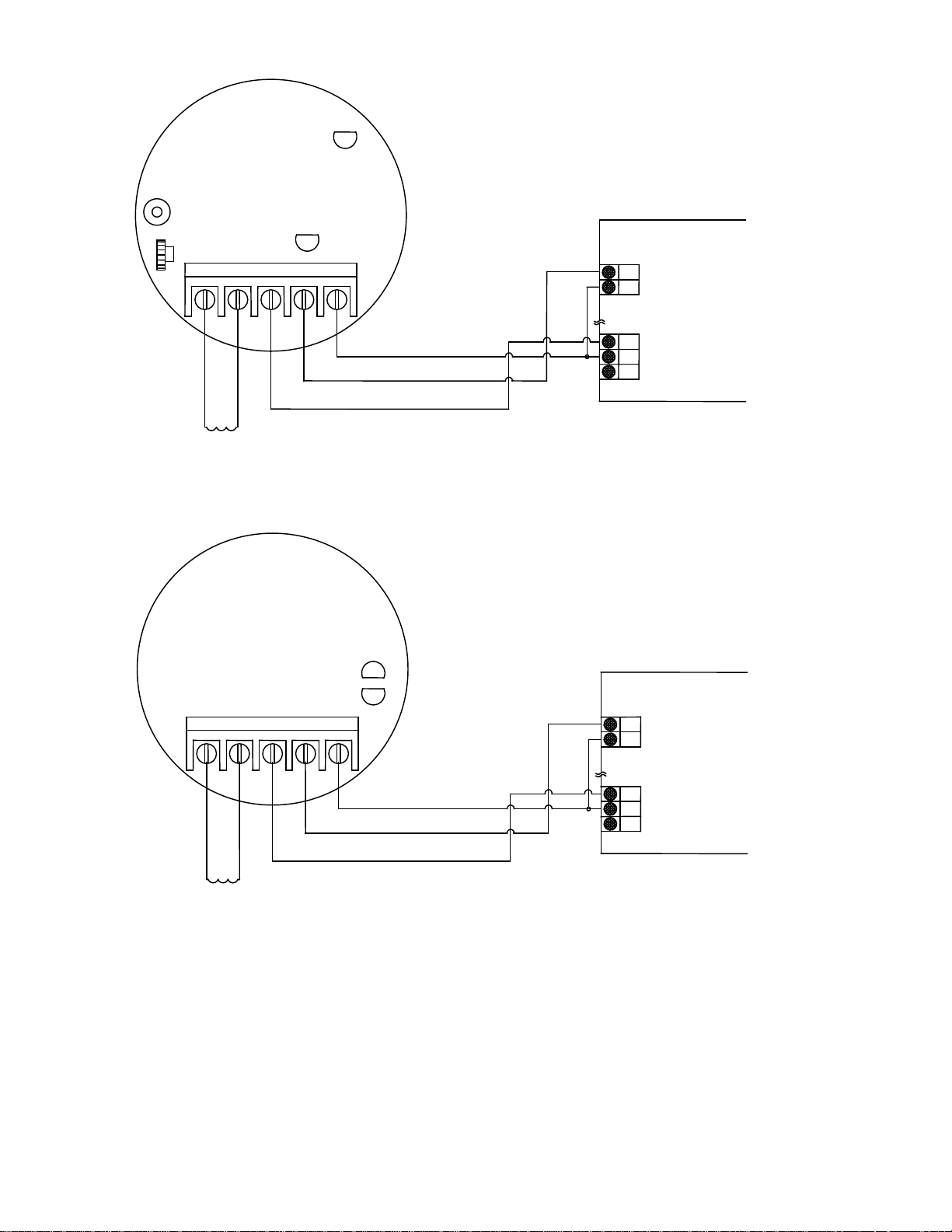
12
12345
17
183031
32
171830
31
32
12345
SP714 REV B
POWER
D1
TEST
SENS
S1
R1
J1
OUTPUT SIGNAL
D2
- DC (GND)
SIGNAL OUT +
+24 VDC
PICKUP COIL
A SIG IN +
B SIG IN -
FLOW COMPUTER
PULSE INPUT
GROUND (SHIELD)
+ 24 V
24 V RETURN
CHASSIS GROUND
PULSE INPUT CONNECTION
FLOW COMPUTER
PULSE INPUT
GROUND (SHIELD)
+ 24 V
24 V RETURN
CHASSIS GROUND
PULSE INPUT CONNECTION
J1
- DC (GND)
SIGNAL OUT +
+24 VDC
PICKUP COIL
A SIG IN +
B SIG IN -
(JU1 INSTALLED)
D1
SP717 REV A
(JU1 INSTALLED)
OUTPUT SIGNAL
D2
Figure 2-3
SP714 & SP717 Pulse Amplifiers Wiring Diagram
Page 13
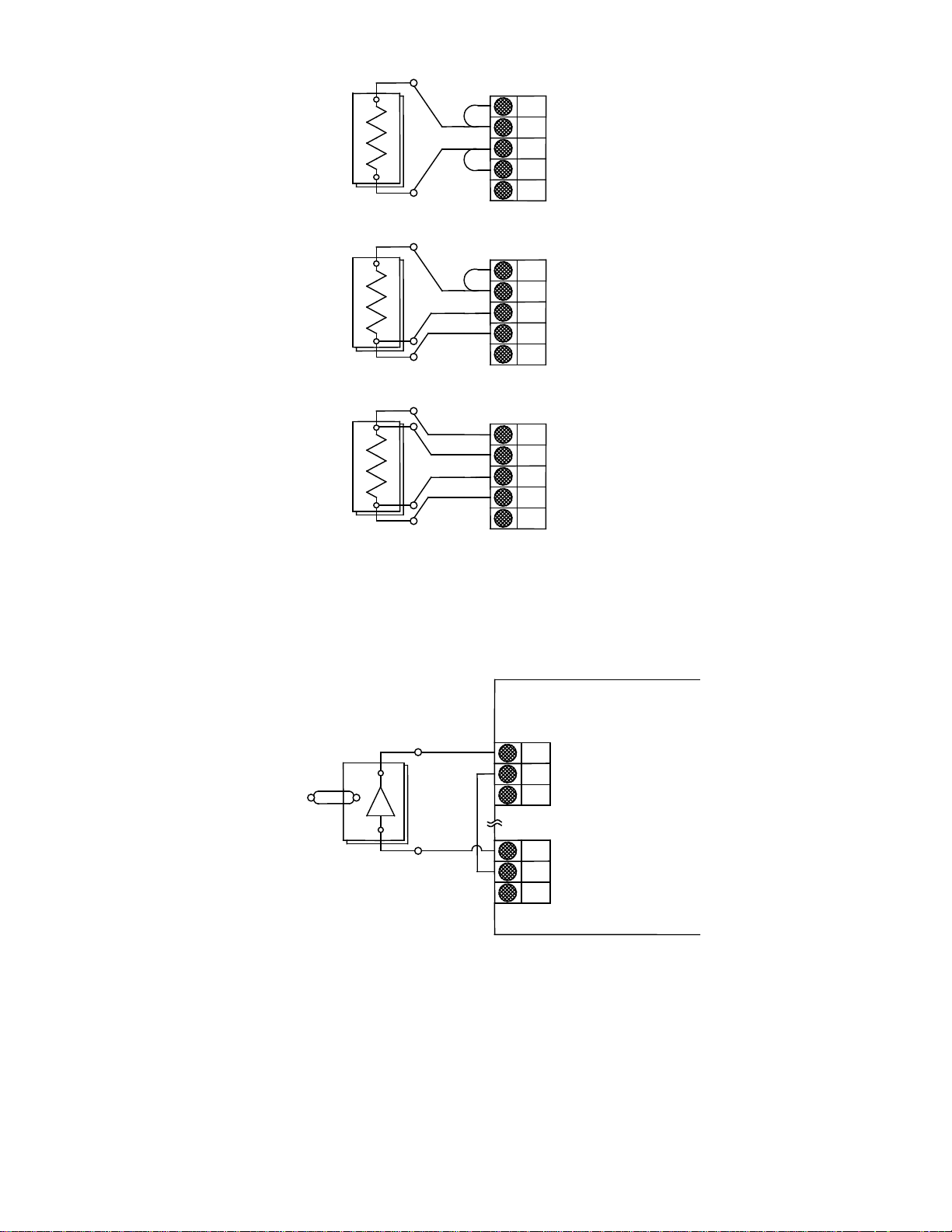
13
2 WIRE CONNECTION
RTD EXCITATION +
GROUND (SHIELD)
4 WIRE CONNECTION
RTD WIRING DIAGRAMS
I IN +
CHASSIS GROUND
456
303132
3 WIRE CONNECTION
1
2 3 4 5 1 2 3 4 5
RTD SENSE +
RTD SENSE -
RTD EXCITATION GROUND (SHIELD)
1 2 3 4 5
RTD SENSE +
RTD SENSE -
RTD EXCITATION GROUND (SHIELD)
RTD EXCITATION +
RTD SENSE +
RTD SENSE -
RTD EXCITATION -
4-20mA T/C
TRANSMITTER
TEMPERATURE TRANSMITTER
4-20mA CONNECTION
FLOW COMPUTER
GROUND (SHIELD)
V IN +
+ 24 V
24 V RETURN
Figure 2-4
Temperature Transmitter Input Wiring Diagrams
Page 14
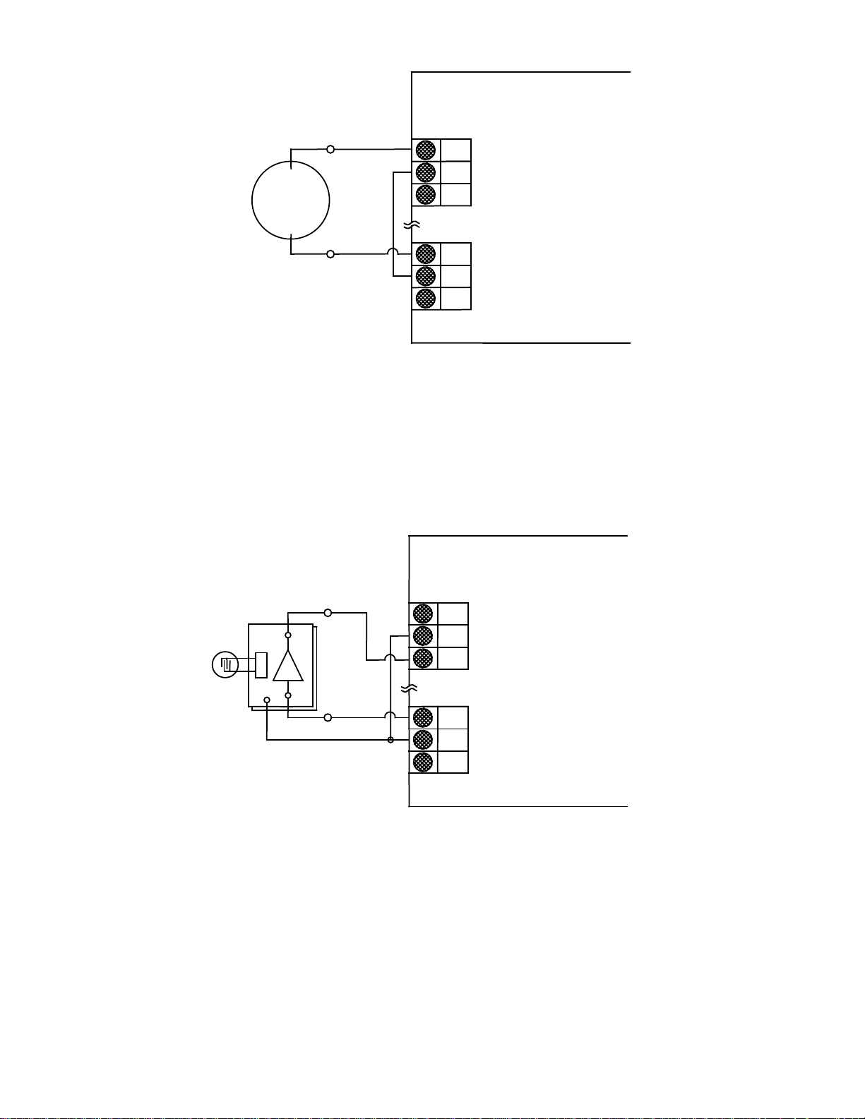
14
+
10
-
-
I IN +
GROUND (SHIELD)
V IN +
+ 24 V
24 V RETURN
CHASSIS GROUND
FLOW COMPUTER
4-20Ma PRESSURE
TRANSMITTER
11
12
30
31
32
4-20mA CONNECTION
10
I IN +
GROUND (SHIELD)
V IN +
+ 24 V
24 V RETURN
CHASSIS GROUND
FLOW COMPUTER
5 VOLT PRESSURE
TRANSMITTER
11
12
30
31
32
0-5 VOLT CONNECTION
Figure 2-5
Pressure Transmitter
Analog Input Wiring Diagrams
Page 15
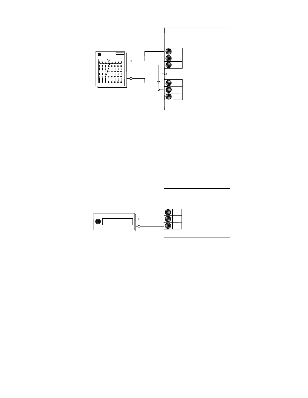
15
FLOW COMPUTER
192021
30
31
32
STRIP CHART
192021
COUNTER
12345678
RECORDER
-
+
ANALOG OUTPUT CONNECTION
SINK (4-20mA)
PULSE OUT
GROUND (SHIELD)
+ 24 V
24 V RETURN
CHASSIS GROUND
Figure 2-6
Analog Output Wiring Diagram
FLOW COMPUTER
REMOTE ELECTRONIC
+
-
PULSE OUTPUT CONNECTION
SINK (4-20mA)
PULSE OUT
CHASSIS GROUND
Figure 2-7
Pulse Output Wiring Diagram
Page 16
16
Figure 2-8: Wiring Diagram-2-wire Probe
Page 17
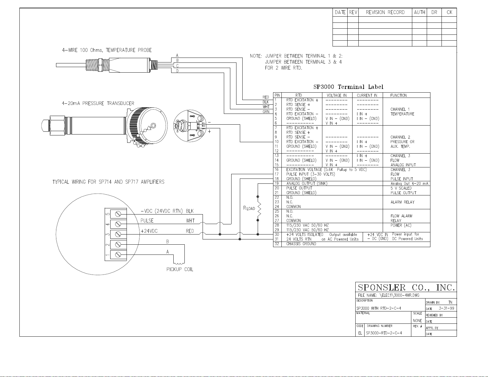
17 Figure 2-8: Wiring Diagram-2-wire Probe
Page 18

18
PROGRAMMING CONSIDERATIONS
Run? Allows crossover from Setup to Run
Go To Standby? Allows crossover from Run to
made
Programming the SP3000 Flow Computer for the desired operation is very simple. All programming
selections and data entry are accomplished via the 16 keys located and labeled on the front panel. The
software in the unit contains two Top Level Menus: “Setup” Menu and “Running” Menu. The “Setup” Menu
allows the selection of operating parameters and entry of data variables. The “Computation” selection sets
the formulas used to process the raw input data into meaningful information. The “Engineering Units”
selection establishes the measuring system that is used for entry and display of the data. The “Hardware”
selection sets the type of input data and activates the proper input terminals on the rear of the unit. The
unit will automatically determine the setup parameter requirements based on the “Computation” and
“Hardware” selections. Prompts are displayed for entry of the required data as the operator progresses
through the setup menu. To aid in the setup, a calibration worksheet is provided. Fill out the worksheet
before beginning setup. Review this section for setup procedures and follow the worksheet for data to be
entered.
The “Running” menu allows the setup of the data display and examination of the programmed operating
parameters. The parameters may not be changed in the “Running” menu.
Either menu allows checking the alarm, clearing the totalizer, or accessing the lock.
Structural Division of the two Top Level Menus:
SETUP MODE RUNNING MODE
Sponsler V6.13 MS197
Run?
Set Computations?
Engineering Units?
Set Hardware?
Set Variables?
Clear Totalizer?
Check Alarm?
Lock/Unlock?
Real Time Clock?
Serial Interface?
Running...
Show Data?
Go To Standby?
Setup Data Display?
Setup Print List?
Print System Setup?
Clear Totalizer?
Examine Hardware?
Examine Comps?
Examine Variables?
Check Alarm?
Lock/Unlock?
When in this mode, the operating
parameters of the instrument may be set
up or changed
In either mode, check alarm, clear totalizer, or the lock may be accessed.
NOTE: Locking the unit in either mode prevents crossover to the other mode.
Setup
When in this mode, the operating parameters
may be examined, but no changes may be
Page 19

19
3.1 FRONT PANEL KEYPAD OPERATION
SPONSLER CO., INC.
123
473
6
9
8
0
SP3000
A
B C D
0
9
DEC. PT.
CANCEL
BACKUP
ENT
CLR
Programming is accomplished via the 16 keys labeled and located on the front panel.
Sponsler V6.13 MS197
Run?
ADVANCE
BACKUP CANCEL DEC PT
A B C D
ENT CLR
The function of each key is described below:
ADVANCE
Advances to the next item in the menu or sub-menu. If the last item in the menu is displayed,
pressing this button will have no effect on the display. The display will not wrap around to the top
of the menu.
Backs up to the previous item on the menu or sub-menu. If the first item in the menu is displayed,
pressing this button will have no effect on the display. The display will not wrap around to the
bottom of the menu.
Cancels current operation and goes back to the top of the menu or sub-menu. From any point in
the menu structure, pressing “Cancel” twice will always return to Run? Or Show Data? Option.
Inserts a decimal point in the numerical value being entered.
THRU
Keys used to enter numbers. Numerical values appear from left to right as keys are pressed.
When entering numerical values, pressing this key will erase the last digit typed. If a previously
entered value is displayed, pressing this key will erase the entire value.
Enters a selection or displayed value. If a parameter prompt is displayed, pressing this key will
display the value presently in memory. If there is no default or previously stored value, an error
message will be displayed.
NOTE: The unit must be in the “Setup” mode to program or change operating parameters. On power up,
the unit will return to the mode in which it was operating when power was removed. If the unit was
operating in the “Running” mode, the unit will display operating data on the power up. To enter the “Setup”
mode:
Page 20

20
DISPLAY SHOWS
the Top Level Menu
A
A
ENT
A
B
C
C
PRESS
Operating Data Scroll
Running...
Show Data?
Running...
Go to Standby?
Sponsler V6.13 MS197
Run? (This display indicates that the unit is in the
“Setup” mode. If the unit was in the “Setup” mode
when the power was removed, the unit will return
to this display on power up)
The function keys allow entry to the menus and sub-menus for selecting operating options or entering
numerical parameters.
Press
Press
Press
Press
Press
Press
Press
ENT
ENT
ENT
ENT
To advance a menu or sub-menu
To backup a menu or sub-menu
To access a menu or sub-menu
To select a displayed option. When an option has
been selected, the unit will autom atical l y advanc e to
the next menu item
To view the previously entered value at any data entry
point.
To erase the last digit typed or to erase a previously
entered value
To cancel current operation and return to the top of the
menu or sub-menu. From any point in the menu
structure, pressing twice will return to the top of
3.2 SETTING COMPUTATIONS
The computation selects the formulas that are used to process the raw input data into meaningful
information. Section 9 details the formulas used in each computation.
Flow Computation Selection and Applications
Ideal Gas – Volume: uses volume, temperature and pressure to yield a compensated
Volumetric flow rate displayed in SCFM (Nm3/h) and total in SCF
(Nm3)
Ideal Gas – Mass: uses volume, temperature to yield a compensated a Mass flow
rate displayed in lbm/h (kg/h) and total lbm (kg)
Steam Tables – Mass: uses volume and temperature and/or pressure to yield a
compensated Mass flow rate displayed in lbm/h (kg/h) and total in
lbm (kg). The unit may be set up to follow saturated steam curve;
see SPECIAL NOTE on page 3-9. (Steam tables are saturated 1
PSIA to 3200 PSIA with super heated values up to 900
o
F. Higher
temperatures cause an alarm condition).
Page 21

21
Liquids – Mass: uses volume and temperature to yield a compensated Mass flow
A
ENT
A
B
ENT
rate displayed in lbm/min (kg/h) and total in lbm (kg).
Liquids – Volume: uses volume and temperature to yield a compensated Mass flow
rate displayed in GPM (1/s) and total in gallons (liters).
Heat – Gas: uses volume, pressure and temperature to yield a compensated
Mass flow rate displayed in lbm/h (kg/h) and total in lbm (kg) as
well as Heat flow rate displayed in Btu/h (kW, kcal/h, MJ/h) and
total in kBtu (kWh, Mcal, MJ).
Heat – Steam: uses volume and pressure and/or temperature to yield a
compensated Mass flow rate displayed in lbm/h (kg/h) and total in
lbm (kg) as well as Heat flow rate displayed in Btu/h (kW, kcal/h,
MJ/h) and total on kBtu (kWh, Mcal, MJ). (Unit may be set up to
follow saturated steam curve, see SPECIAL NOTE, pg. 3-9)
Heat – Liquid: uses volume and temperature to yield a compensated Mass flow
rate displayed in lbm/min (kg/h) and total in lbm (kg) as well as
Heat flow rate displayed in Btu/h (kW, kcal/h, MJ/h) and total in
kBtu (kWh, Mcal, MJ).
Del Heat – Liquids: uses volume and two temperatures to yield a compensated Mass
flow rate displayed in lbm/min (kg/h) and total in lbm (kg) as well
as Heat flow rate displayed in Btu/h (kW, kcal/h, MJ/h) and total in
kBtu (kWh, Mcal, MJ).
To access the Computation Menu:
Display Shows:
Press:
Sponsler V6.13 MS197
Run?
Sponsler V6.13 MS197
Set Computations?
Flow Computations: to advance the menu
Ideal Gas – Volume?
to backup menu
to select the displayed
computation
The nine options available in the Computations Menu are:
Ideal Gas – Volume?
Ideal Gas – Mass?
Steam Tables – Mass?
Liquids – Mass?
Liquids – Volume?
Heat – Gas?
Heat – Steam?
Heat – Liquid?
Del Heat – Liquids?
Page 22

22
3.3 SELECTING THE ENGINEERING UNITS
ENT
ENT
A
B
ENT
Engineering units establish the measuring system that is used for entry and display of the operating
parameters.
Four options are available to select the desired units for the application:
English (Imperial): Temperature
kPa (Metric): Temperature
2
Kg/cm
(Metric) Temperature oC; Pressure kg/cm2
bar (metric) Temperature
NOTE: The output data display units and the required variable units are determined by the
Computation and Engineering Units selected. A complete listing of input and output data units is given
in Appendix i.
To enter the Engineering Units Menu:
Display Shows:
Sponsler V6.13 MS197
Engineering Units?
Engineering Units? To advance menu
English?
To backup menu
To select displayed option
Engineering Units Menu:
Engineering Units:
English?
Engineering Units:
kPa (Metric)?
Engineering Units:
2
kg/cm
(Metric)?
Engineering Units:
bar (Metric)?
3.4 SETTING THE HARDWARE
The hardware selection determines the input terminals from which the unit will accept raw data. Internal
analog switches activate the proper terminals for the input type selected. Review the specification sheet for
each input device being used with the system to determine the required selection.
To access the Hardware Menu:
Display Shows:
Press:
Sponsler V6.13 MS197
Set Hardware?
o
F; Pressure PSI
o
C; Pressure kPa
o
C; Pressure bar
Press:
Page 23

23
Input Configuration:
A
ENT
A
A
ENT
ENT
ENT
Pressure? To advance Input Configuration
Menu
To access Pressure Input Type
Menu
Flowchart Representation of Hardware Menu:
Sponsler V6.13 MS197
Set Hardware?
ENT
Input Configuration? Input Configuration? Input Configuration?
Pressure? Temperature? Flow?
Input Type: Input Type: Input Type:
5 Volts? 5 Volts? 5 Volts?
10 Volts? 10 Volts? 10 Volts?
0-20mA? 0-20mA? 0-20mA?
4-20mA? 4-20mA? 4-20mA?
RTD (100 ohms) Digital Pulse
or*
Sub-Menu
Input Configuration:
Temperature two? Flowmeter Type:
Linear?
ENT
Orifice/Pitot?
Sixteen Point?
Input type:
5 Volts?
10 Volts?
0-20mA?
4-20mA?
RTD (100 ohms)?
* Channel 2 may be a pressure or temperature input depending on which computation is selected. The
pressure sub-menu is replaced by the temperature two sub-menu if the Del-Heat-Liquids Computation is
selected.
NOTE:
The pressure input is always the gage pressure of the line. Differential pressure is selected under the flow input type.
Input type “5 Volts?” is a 0 to 5 volt signal. 1 to 5 volt signals cannot be handled properly due to software constraints.
Input type “10 Volts?” is a 0-10 volt signal.
The flowmeter type sub-menu directly follows the flow input type.
Flowmeter types:
LINEAR is selected whenever the signal from the flowmeter is linear over the operating range.
ORIFICE/PITOT is the selection when the signal from the flowmeter represents a square law differential pressure. This
type is not available when Digital Pulse is selected as the input type.
SIXTEEN POINT is for compensating any other type on non-linear input sig nal s.
* * BE SURE THAT INPUT DEVICES ARE WIRED TO THE PROPER TERMINALS. IF HARDWARE SELECTION
DOES NOT MATCH WIRING, THE RESULT WILL B E ERRONEOUS READINGS.
Page 24

24
3.5 SETTING THE VARIABLES
At input = Minimum --
Enter the gage pressure value represent ed b y the
At input = Maximum --
Enter the gage pressure value represent ed b y the
10)
Atmospheric Pressure --
This value is added to the input gage pressure to
CLR
ENT
A
B
ENT
D
The variables determine how the input signals are interpreted by the software to display and output the
compensated flow. The parameters required for proper calculation are determined by the Computation,
Engineering Units, and Hardware Selections. The unit will automatically prompt for the required
parameters.
Use the numeric keypad to input the required variables. The key sets the decimal point when entering
a numerical value. The key acts as a backspace (erases the last digit typed) when entering a
numerical value. The key enters the data into memory.
To access the Variable Menu:
Display Shows:
Sponsler V6.13 MS197
Set Variables?
Select Setup Item: to advance Variable Menu
Pressure input
to backup menu
to access Pressure input
sub-menu
3.51 SETTING THE PRESSURE VARIABLES
The Pressure Variables determine how the input signals from channel 2 are interpreted. The
Pressure sub-menu is the same for all Computation and Hardware selections. The Engineering
units selected determine the pressure input units. The pressure input is always the gage pressure
of the line.
NOTE:
The Pressure sub-menu is replaced by a second temperature sub-menu if the Computation is DelHeat-Liquids.
The Pressure input is not required for Liquids-Mass or Volume computations. The functionality of
the input terminals and the sub-menu remain active and may be used if desired.
The Pressure Input Sub-menu & Definitions of Required Data:
Select Setup Item:
Pressure input?
ENT
Press:
ENT
Lo press?
Hi press?
Barometric?
lowest analog input (i.e. 4mA=10 PSIG. Enter 10)
highest analog input (i.e. 20mA=500 PSIG. Enter
calculate the absolute pressure value (i.e. 14.696
PSIA. Enter 14.696)
Page 25

25
Press alarm set point --
Lo alarm?
Enter Low Pressure value at which the unit activat es
Press alarm set point --
Enter High Pressure value at which the unit activates
PSIG)
NOTES
At input = Minimum --
Enter the temperature value repres en ted b y the
1
At input = Maximum --
Enter the temperature value repres en ted b y the
2
Base Reference --
Enter the temperature value at which the sp ecif ic
Temp alarm set point --
Enter Low Temperature value at which the unit
Temp alarm set point --
Enter High Temperature value at which the unit
0 0 0
ENT
an alarm relay (i.e. 5PSIG. Enter 5. Alarm relay is
activated when pressure input indicates 5 PSIG)
Hi alarm?
an alarm relay (i.e. 500 PSIG. Enter 500. Alarm
relay is activated when pressure input indicates 500
SPECIAL NOTE: To set the flow computer to follow the saturated steam curve with
1. Pressure and No temperature inputs: set Lo temp = 0.00 and Hi temp = 0.00. The
flow computer will use the pressure input to look up the corresponding temperature
on the saturated steam table for calculations and display.
2. Temperature and No pressure input: set Lo press = 0.00 and Hi press = 0.00.
The flow computer will use the temperature input to look up the corresponding
pressure on the saturated steam table for calculations and display.
3.52 SETTING THE TEMPERATURE VARIABLES
The temperature variables determine how the input signals from channel 1 * are interpreted. The
temperature sub-menu is determined by the Computation and Hardware selections.
NOTE:
* The Pressure sub-menu is replaced by Temperature 2 sub-menu if the Computation is Del-HeatLiquids. Follow the same setup procedure as outlined in this section.
Entering Negative Values:
A leading minus sign may be entered by pressing the key as the first keystroke when entering
a numerical temperature value.
Subsequent strokes of the key will enter zero into the number as usual. The key acts
conventionally in all other variab le su b-menus.
The Temperature Input Sub-menu & Definitions of Required Data:
Select Setup item:
Temperature input?
1
Lo temp?
Hi temp?
Temperature?
Lo alarm?
Hi alarm?
lowest analog output (i.e. 4mA=32o F. Enter 32)
highest analog input (i.e. 20mA=240oF. Enter 240)
gravity is measured (i.e. 60oF. Enter 60)
activates an alarm relay (i.e. 20o F. Enter 20. Alarm
relay is activated when temperature input indicates a
temperature of 20
o
F)
activates an alarm relay (i.e. 850o F. Enter 850.
Alarm relay is activated when pressure input
indicates a temperature of 850
o
F)
Page 26

26
NOTES
Pulses per unit vol.
Enter the K-Factor (Pulses per unit volume) from the
2
Specific gravity
Enter the specific gravity constant calculated at
3
Thermal Expansion
Enter the thermal coefficient of expansion for the
4
Mean
Enter the constant value for the ability of the liquid to
Cutoff: 0 to 40 KHz
Enter the highest pulse rate (frequency) at which the
width required
Flow alarm set point
Enter the low compensated flowrat e value at which
Flow alarm set point
Enter the high compensated flowrate va lu e at whic h
Notes:
1. These prompts do not appear if Hardware is RTD (100 ohms). The resistance input is
referenced to a look-up table to determine the temperature.
2. This prompt appears if a liquid computation is selected (Liquid-Mass, Liquid-Volume, Heat-
Liquid, Del Heat-Liquids).
3.53 SETTING THE FLOW VARIABLES
The Flow variables determine how the input signals from channel 3 are interpreted. The flow input
sub-menu will only prompt for the required variables as determined by the Computation and
Hardware selections. Flowcharts showing complete sub-menu prompts are given for each of the
Hardware selections. Use the flowchart corresponding to the Hardware selected and observe
notes as to which variables are required for the Computation selected.
HARDWARE SELECTIONS
Input Type Use Flow Chart
Page
Digital Pulse-Linear 3.54 3-10
Digital Pulse-Sixteen Point 3.55 3-11
Analog-Linear 3.6 3-15
Analog-Sixteen Point 3.61 3-16
3.54 FLOWCHART: DIGITAL PULSE-LINEAR
Select Setup item:
Flow input?
ENT
K-Factor?
1 Gas compressibility
Z Factor?
Gravity?
C(X10E-6)?
Spec Heat?
Input filter?
Lo alarm?
Hi alarm?
flowmeter calibration data sheet
Enter the Compressibility factor of the gas being
measured
Standard or the Base Reference Temperature for the
product being measured
liquid being measured
retain heat.
unit will accept pulses. Higher pulse rates are
ignored. NOTE: Also determines the minimum pulse
the flow alarm relay will activate
the flow alarm relay will activate
Page 27

27
NOTES:
NOTES
2
Specific gravity
Enter the specific gravity constant calculated at
3
Thermal Expansion
Enter the Thermal Coefficient of Expansion for the
Cutoff: 0 to 40 KHz
Enter the highest pulse rate (frequency) at which the
Flow alarm set point
Enter the high compensated flowrate va lu e at whic h
ENT
ENT
A
1. Used in Ideal Gas equation only.
2. Not used in Idea Gas-Volume or Steam equations.
3. Used in Liquids equations only.
4. Used in Heat-Gas, Del-Heat-Liquids and Heat-Mass equations only.
3.55 FLOWCHART: DIGITAL PULSE- SIXTEEN POINT
Select input item:
Flow input?
Linearize
16 Point?
Enter Point
Freq. 01?
** Refer to section 3.551 & 3.552 for
complete 16 point menu and
programming example
1 Gas Compressibility
Z Factor?
Gravity?
C(X10E-6)?
4 Mean
Spec Heat?
Input filter?
Flow alarm set point
Lo alarm?
Hi alarm?
NOTES:
1. Used in Ideal Gas equations only.
2. Not used in Ideal Gas-Volume or Steam equations.
3. Used in Liquids equations only.
4. Used in Heat-Gas, Del Heat-Liquids, and H eat-Mass equations only.
Enter the compressibility factor of the gas being
measured
Standard or the Base reference temperature for the
product being measured
liquid being measured
Enter the constant value for the ability of the liquid to
retain heat
unit will accept pulses. Higher pulse rates are
ignored. NOTE: Also determines the minimum pulse
width required
Enter the low compensated flowrate value at which
the flow alarm relay will activate
the flow alarm relay will activate
Page 28

28
3.551 DIGITAL PULSE – SIXTEEN POINT PROGRAMMING
C
The 16 Point Linearization is used when the flowmeter gives a non-linear signal. The unit
uses up to 16 different frequency and K-Factor entries to form a curve for linearizing the
input signal.
SPONSLER, INC. STRONGLY RECOMMENDS THOROUGH REVIEW AND
UNDERSTANDING OF THIS SECTION PRIOR TO PROGRAMMING THE 16 POINT
MENU.
NOTES:
1 A minimum of three points must be set up.
2. If two consecutive input values or K-Factors are set to zero, extrapolation is taken from
the last two non-zero points to determine a K-Factor used for calculations.
3. If the input frequency is above the highest or below the lowest frequency programmed,
the unit will use the last two points to extrapolate the K-Factor and calculate the
resulting actual flow. Care must be taken that the K-Factor doesn’t extrapolate to zero.
If this happens, the unit will give erroneous readings. To avoid this occurrence,
program point 01 frequency at zero and point 01 K-Factor at the same K-Factor for the
lowest input frequency as listed in the flowmeter calibration sheet.
4. Frequencies must be entered in ascending order.
not
5. The 16 point option will
in the Flow Variables menu.
6. Press the button when the desired number of points are entered. This will exit the
16 Point Setup routine and return to “Set Variables?” heading. If all 16 points are
programmed, the unit will automatically advance to the next required Setup item.
override the cutoff Input Filter frequency entered elsewhere
Page 29

29
3.552 PROGRAMMING EXAMPLE: `Flowchart: Digital Pulse – Sixteen Point
Select Setup item:
Linearize
Enter point
Press 0
Freq 09? 834.0000
Press 2274834
Freq 01? 0.0000
Press 1383067
Enter point
Press 948
Enter point
Press 32
Freq 10? 958.0000
Press 2303039
Freq 02? 32.0000
Press 1383067
Enter point
Press 1058
Enter point
Press 148
Freq 11? 1058.0000
Press 2323958
Freq 03? 148.0000
Press 2160356
Enter point
Press 1290
Enter point
Press 259
Freq 12? 1290.0000
Press 2384127
Freq. 04? 259.0000
Press 2161185
Enter point
Press 1514
Enter point
Press 377
Freq 13? 1514.0000
Press 2417309
Freq 05? 377.0000
Press 2203285
Enter point
Press 1741
Enter point
Press 492
Freq 14? 1741.0000
Press 2440122
Freq 06? 492.000
Press 2224646
Enter point
Press 1966
Enter point
Press 601
Freq 15? 1966.0000
Press 2458372
Freq 07? 601.000
Press 2235430
Enter point
Press 2195
Enter point
Press 723
Freq 16? 2196.0000
Press 2479318
Freq 08? 732.0000
Press 2256791
Gas Compressibility
ENT
ENT
ENT
ENT
ENT
ENT
ENT
ENT
ENT
ENT
ENT
ENT
ENT
ENT
ENT
ENT
ENT
Flow input?
**NOTE: This is an example of 16 point programming using calibration data for turbine Serial No. 107221. (See
next page) Actual Calibration data must be entered for the specific turbine flowmeter used with the unit.
16 point?
ENT
Freq 01?
K-Factor 01?
Freq. 02?
K-Factor 02?
Freq 03?
K-Factor 03?
Freq 04?
K-Factor 04?
Freq 05?
Press
Press
Press
Press
Press
Press
Press
Press
Press
ENT
ENT
ENT
Enter point
Freq 09?
K-Factor 09?
Freq 10?
K-Factor 10?
Freq 11?
K-Factor 11?
Freq 12?
K-Factor 12?
Freq 13?
K-Factor 13?
Press 834
Press
ENT
Press
Press
Press
ENT
ENT
Press
Press
ENT
Press
Press
Press
Press
K-Factor 05?
Freq 06?
K-Factor 06?
Freq. 07?
K-Factor 07?
Freq 08?
K-Factor 08?
NOTE: To view the previously entered value at any data entry point, press ENT. The stored value will display. If the display value doesn’t need
to be changed, press ENT. The value will be retained and the unit will automatically advance to the next data entry point. If the value needs to
be changed, press CLR. Press the number keys to display the desired value to be entered, then press ENT. The value will be stored and the
unit will automatically advance to the next data entry point.
Press
Press
Press
Press
Press
Press
Press
ENT
ENT
ENT
ENT
Freq 14?
K-Factor 14?
Freq 15?
K-Factor 15?
Freq 16?
K-Factor 16?
Z Factor
Press
Press
Press
Press
Press
Press
ENT
ENT
ENT
ENT
ENT
Page 30

30
PT
16
0
MEAN TOTAL CYCLES (PER WEIGHT USED):
10
11
12
13
141516
1383067.5
1383067.5
2160356.1
2161185.6
2203285.3
2224646.2
2235430.4
2256791.3
2274834.0
2303038.7
2323984.8
2343271.9
2384127.2
2397400.0
2417309.2
2433070.7
2440121.9
2448624.8
2458372.0
2471437.4
2479318.1
32
148
259
377
492
601
723
834
948
1058
1176
1290
1398
1514
1637
1741
1861
1966
2087
2195
6669
10417
10421
10624
10727
10779
10882
10969
11105
11206
11299
11496
11560
11656
11732
11766
11807
11854
11917
11955
208.145
70.417
40.221
28.192
21.816
17.918
15.058
13.147
11.720
10.589
9.605
8.909
8.267
7.698
7.166
6.760
6.345
6.030
5.710
5.447
0.0014
0.0041
0.0072
0.0103
0.0133
0.0161
0.0192
0.0220
0.0247
0.0273
0.0301
0.0325
0.0350
0.0376
0.0404
0.0428
0.0456
0.0480
0.0507
0.0531
0.004822
65
0.9986
0.036022
0.30000
20
19
18
17
16
15
14
13
12
11
10
9
8
7
6
5
4
3
2
1
USA
WESTMINSTER S.C. 29693
2363 SANDIFER BLVD.
SPONSLER CO., INC.
1ea.
CRYO
17-4
304
107211
COIL NO.
:RF22M
BEARINGS:
ROTOR MATERIAL:
HOUSING MATERIAL:
SERIAL NO.:
MODEL NO.: MF40-CB-PH-1/4A-4RFX
HR
2
AIR
1
9334
CPFT3
"K"
FREQ. CPS
APPROX.
CYCLES
TOTAL
SECONDS
TIME
ACFM
RATE
ACFM
TRUE VOL.
DEG.FAR.
TEMP.
SP.GR.
(TRUE)
SP.GR.1.000
VOL.GALLONS
LBS.
WEIGHT
PT.
DATE: 13-Jan-92
CALIBR AT ED BY:
TEST STAND NO.:
FLUID:
CALIBRATION #:
WORK ORDER #:
SENSING ELEMENT CONSTANT (MEAN CYCLES/ACF):
09
08
07
06
05
04
03
02
01
*
NOTE: 16 Point Linearization frequency points must be in ascending order. Disregard the PT column on the left;
Calibration Data points are in descending order.
Establish the points that require linearization based on the flowrate range required and the non-linearity of the
specific meter.
* Point 01 frequency should be “0”, with K-Factor of lowest frequency listed.
Page 31

31
3.6 ANALOG LINEAR INPUT SETTINGS
NOTES
Select Setup item:
1
Gas compressibility
Enter the compressibility factor of the gas being
2
Specific gravity
Enter the specific gravity constant calculated at
At input = minimum
Enter the flow value at which the analog input is
At input = maximum
Enter the flow value at which the analog input is
Low flow
Enter the lowest flow value below which any
3
Thermal Expansion
Enter the Thermal Coefficient of Expansion for the
4
Mean
Enter the constant value for the ability of the liquid to
Flow alarm set point
Enter the low compensated flowrat e value at which
Flow alarm set point
Enter the high compensated flowrate value at which
Graphical representation of the Analog Linear sub-menu
Flow input?
ENT
Z Factor?
Gravity?
Lo flow?
Hi flow?
Cutoff?
C(X10E-6)?
Spec Heat?
measured
standard or the Base Reference Temperature for the
product being measured
lowest (i.e. no flow = 4.00mA. Enter 0)
highest (i.e. 300 m3/hr = 20.00mA. Enter 300)
calculations are unnecessary. For example, a small
leakage when valve is closed to be ignored
liquid being measured
retain heat
Lo alarm?
Hi alarm?
NOTES:
1. Used in Ideal Gas equations only.
2. Not used in Ideal Gas-Volume or Steam equations.
3. Used in Liquids equations only.
4. Used in Heat-Gas, Del Heat-Liquids, and H eat-Liquids equations only.
the flow alarm relay will activate
the flow alarm relay will activate
Page 32

32
3.61 ANALOG 16 POINT INPUT SETTINGS
NOTES
ENT
ENT
Select Setup item:
Flow input?
Linearize
16 Point?
1 Gas compressibility
Z Factor?
2 Specific gravity
Gravity?
At input = minimum
Lo flow?
At input = maximum
Hi flow?
Low flow
Cutoff?
3 Thermal Expansion
C(X10E-6)?
ENT
Enter Point
Actual 01?
Actual 01? 0.000
K-Factor 01?
Enter the compressibility factor of the gas being
measured
Enter the specific gravity constant calculated at
standard or the Base Reference Temperature for the
product being measured
Enter the flow value at which the analog input is
lowest (i.e. no flow = 4.00mA. Enter 0)
Enter the flow value at which the analog input is
highest (i.e. 300 m
3
/hr = 20.00mA. Enter 300)
Enter the lowest flow value below which any
calculations are unnecessary. For example, a small
leakage when valve is closed to be ignored
Enter the Thermal Coefficient of Expansion for the
liquid being measured
4 Mean
Spec Heat?
Flow alarm set point
Lo alarm?
Flow alarm set point
Hi alarm?
Enter the constant value for the ability of the liquid to
retain heat
Enter the low compensated flowrat e value at which
the flow alarm relay will activate
Enter the high compensated flowrate va lu e at whic h
the flow alarm relay will activate
NOTES:
1. Used in Ideal Gas equations only.
2. Not used in Ideal Gas-Volume or Steam equations.
3. Used in Liquids equations only.
4. Used in Heat-Gas, Del Heat-Liquids, and H eat-Liquids equations only.
Page 33

33
3.7 ANALOG ORIFICE/PITOT INPUT SETTINGS
NOTES
ENT
Graphical representation of the Analog Orifice/Pitot sub-menu
Select Setup item:
Flow input?
1 Gas compressibility
Z Factor?
2 Specific gravity
Gravity?
Meter compensation
Factor (K1)?
At input = minimum
Delta P lo?
At input = maximum
Delta P hi?
Low Flow
Cutoff?
3 Thermal Expansion
C(X10E-6)?
4 Mean
Spec Heat?
Flow alarm set point
Lo alarm?
Flow alarm set point
Hi alarm?
NOTES:
1. Used in Ideal Gas equations only.
2. Not used in Steam equations only.
3. Used in Liquids equations only.
4. Used in Heat-Gas, Del Heat-Liquids, and H eat-Liquids equations only.
Page 34

34
3.8 SETTING THE FLOW OUTPUT VARIABLES
Select Setup item:
Flow at 4mA out
Enter the compensated Flow Rate value to be represented by 4mA
Digital pulse out
Enter a multiplying factor for the 5V digital pulse output. This
increment of the flow totalizer (maximum Output rate is 50 kHz).
A A A A A
The Flow Output Variables determine how the output signals reflect the compensated flow. The Flow
Output sub-menu is the same for all Computation or Hardware Selections.
NOTE: It is not necessary to set up the Flow Output if it is not required.
Flow Output?
ENT
Min flow?
Flow at 20mA out
Max flow?
Scaling?
output
Enter the compensated Flow Rate value to be represented by
20mA output
factor multiplies the incremental counts of the flow totalizer and
outputs a pulse as required.
EXAMPLE:
Scaling factor of 0.1 outputs one pulse for every 10 increments of
the flow totalizer. Scaling factor of 10 outputs ten pulses for each
CLEARING THE TOTALIZER: RESETTING THE TOTALIZER TO 0.000
The totalizer can be cleared (reset to zero) in either of the two top-level menus: “Setup” or “Running”.
NOTE: The totalizer accumulates only while the unit is in the “Running” side of the menu.
To clear Totalizer in “Setup” menu:
Sponsler V6.13 MS197
Run?
Sponsler V6.13 MS197
Set Computations?
Sponsler V6.13 MS197
Engineering Units?
Sponsler V6.13 MS197
Set Hardware?
Sponsler V6.13 MS197
Set Variables?
Page 35

35
Sponsler V6.13 MS197
A
A A A
ENT
A
A
A
Clear Totalizer?
Totalizer Cleared This message is momentarily displayed to verify that the totalizer
Sponsler V6.13 MS197
Check Alarm?
* To Clear Totalizer in “Running” Menu:
Press
Running...
Show Data?
Running...
Go To Standby?
Running...
Setup Display?
Running...
Setup Print List?
Running...
Print System Setup?
Running...
Clear Totalizer?
Totalizer Cleared This message is momentarily displayed to verify that the totalizer
Running...
Show Data?
ENT
is cleared. The menu then advances to the next item
is cleared. The unit then returns to the top of the menu.
Page 36

36
CHECKING THE ALARM: VIEW THE MOST RECENT ALARM CONDITION
ENT
B
A
A
A
ENT B ENT
A
A
A
ENT
If the alarm should go off, the point which went into alarm most recently may be checked and quieted from
either of the Top-Level menus.
To Check the Alarm in “Setup” Menu:
Sponsler V6.13 MS197
Run?
Sponsler V6.13 MS197
Set Computations?
Sponsler V6.13 MS197
Engineering Units?
Sponsler V6.13 MS197
Set Hardware?
Sponsler V6.13 MS197
Set Variables?
Sponsler V6.13 MS197
Clear Totalizer?
Sponsler V6.13 MS197
Check Alarm?
The most recent alarm condition will be
Alarm Condition displayed on the top line. Pressing will
Press ENT to Quiet de-energize the corresponding alarm relay. If
The condition that caused the alarm still exists
When the unit is returned to “Running” mode,
The alarm relay will again energize.
Alarm Condition Momentarily displayed to indicate the alarm
Alarm Cleared has been cleared.
The unit automatically advances to the next
menu.
Sponsler V6.13 MS197 To check that no other alarm condition exists,
Lock/Unlock? press to backup to the check alarm option.
Sponsler V6.13 MS197
Check Alarm?
No Alarm Condition Momentarily displayed to indicate that no alarm conditions exist.
The unit will automatically advance to the next menu.
Sponsler V6.13 MS197
Lock/Unlock?
Page 37

37
LOCK/UNLOCK
Advance or Backup the menu until the display indicates:
Sponsler V6.13 MS197
or
Running...
Machine is unlocked
Enter a 5 digit code number (NOTE: Code may
Machine is unlocked
As soon as the fifth digit is entered, 5 “*”s will be
Machine is unlocked
Now confirm:
Enter the 5 digit code again
Machine is unlocked
As soon as the fifth digit is entered, 5 “8”s will be
Sponsler V6.13 MS197
Running...
After the lock has been initiated in the “Setup” mode, only “:Check alarm?” or “Lock/Unlock”
****Locked!!****
ENT
ENT
Lock is used to prevent unwanted changes to programming. No changes through the front panel or RS232 port can be made while the unit is locked. The lock may be initialized in either the “Setup” or “Running”
mode. Once the unit is locked, the operating mode can’t be changed. If unit is locked in “Setup” mode,
“Running” mode can’t be accessed. If the unit is locked in “Running” mode, “Setup” mode can’t be
accessed.
NOTE: Any 5 digit security code (except 00000) may be used to lock the unit. The same 5 digit code must
be entered to unlock the unit. Place the 5 digit security code used to lock the unit in a safe location for
future reference.
To Lock:
Lock/Unlock
Enter code:
Enter code: *****
Now confirm: *****
Real time clock? or
may be accessed. Any attempt to enter one of the programming menus or the “Running” mode
will display:
Push to continue
Press
Lock/Unlock?
NOT be 00000). As each digit is pressed an “*”
will appear on the display to verify that the digit
has been entered.
displayed momentarily. The unit will then
advance to “Now confirm:”
displayed momentarily. The unit will lock and
then advance to the next menu item.
Show Data?
In the “Running” mode the lock prevents access to “Go to Standby?” and “Clear Totalizer?”. All
other functions of the “Running” menu remain accessible.
Page 38

38
To Unlock:
Machine is locked
Enter the 5 digit code number. No confirming
Machine is locked
The unit will unlock and then advance to the next
Note:
This error message may display after the entry of the 5 digit code
ENT
Advance or Backup the menu until the display indicates:
Sponsler V6.13 MS197
Lock/Unlock
Enter code:
Enter code: *****
Sponsler V6.13 MS197
Real time clock? or
Bad lock code
Push to continue
in the lock/unlock procedure. Pressing enter will exit the
Lock/Unlock menu option and advance to the next menu item.
or
Press
Running...
Lock/Unlock?
ENT
step is required to unlock the unit.
menu item as soon as the correct code is
entered.
Running...
Show Data?
Page 39

39
REAL TIME CLOCK
Sponsler V6.13 MS197
Select item:
Enter time:
Enter the correct hour and minutes based on 24 hour c lock.
Select item:
Enter date:
Enter the correct date in the format: Month (1-12). Date (1-
Sponsler V6.13 MS197
The unit will automatically advance to the next menu item.
NOTE:
Bad Time value
Error messages indicating that the numerical value
or
Bad Date value
Syntax error
Error message indicating that the numerical values
ENT D ENT
ENT
ENT
D
D
ENT
The SP3000 has a real time clock and calendar that can be set from the front keypad while the unit is in
the “Setup” mode. The clock cannot be set while in the “Running” mode. The time and date are saved
upon power down: however, there is no battery backup to update the time and date during loss of power.
NOTE: The time must be in 24 hour format.
Advance “Setup” menu until display indicates:
Real time clock?
Set time?
Enter hours (00-23) and minutes (00-59) based on 24 hour clock.
Example: 2:32 p.m. must be entered as 14:32 (Decimal point must be entered between
hour and minutes).
Hr. Min?
Example: 14 32 (2:32 p.m.)
Press
ENT
Set date?
Mo. Da. Yr. ?
31). Year (00-99) Example: 4 23 92 (April 23,
1992)
Press
Serial Interface?
ENT
Push to continue
entered is invalid.
Push to continue
ENT
Push to continue
are not entered in the correct format.
Page 40

40
RUNNING MODE
Running...
Press to activate the live display of flow data
Running...
Press to access the “Setup” mode for setting variables
Running...
Press to program the order of the live display
Running...
Used with RS-232 option to select the items printed out the
Running...
Used with RS-232 option to print out all parameter values out
Running...
Press to reset the Totalizer to 0.000
Running...
Press to view the Hardware configurations for the
Running...
Press to view the Flow Computation selected
Running...
Press to view the input variables configurations
Running...
Press to view the most recent alarm condition
Running...
Press to access and change the lock function
ENT
ENT
ENT
ENT
ENT
The “Running” mode is the normal operating mode for the SP3000. Flow measurement is performed only
in the “Running” mode.
Top Level Running Menu:
Show Data?
Go to Standby?
Setup data display?
ENT
Setup print list?
Print System setup?
Clear Totalizer?
Examine Hardware?
Examine Comps?
Examine Variables?
Check Alarm?
Lock/Unlock?
serial port
the serial port
ENT
Temperature, Pressure, and Flow Inputs
ENT
ENT
Page 41

41
8.1 SHOW DATA
A
A
ENT
B
ENT
A
C
This menu item will start the data list scrolling on the LCD display. The order of display for up to 16 items
can be designated in the “Setup data display?” menu. Each item can be displayed more than once in the
scan list. Each item will be displayed for approximately two seconds. If an item requires longer display
time, it may be selected for consecutive display points.
The parameters available for display selection (from a total of 19) are dependent upon the Computation
and Hardware setup. The system automatically determines the data available for display based on the
programmed parameters.
DISPLAY DATA DESCRIPTIONS:
1. Time and Date Current time and date
2. Flow Rate Filtered & Compensated with engineer ing un its
3. Mass Flow Filtered & Compensated with engineering units
4. Heat Flow Filtered & Compensated with engineering units
5. Totalizer Compensated accumulated flow with engineering units
6. Totalizer (Mass) Compensated accumulated flow
7. Heat Totalizer Compensated accumulated heat flow
8. Temperature Filtered & Scaled temperature in degrees
9. Pressure Filtered & Scaled pressure in units of measurement
10. Uncompensated Flow Filtered but not compensated with engineering units
11. Raw Flow (Channel 3) Analog value of flow input
12. Raw Pressure (Channel 2) Raw analog value of pressure input
13. Raw Temperature (Channel 1) Raw analog value of temperature input
14. Raw RTD Input 1 Raw analog value of RTD input in mA
15. RTD Ohms (Channel 1) Resistance of RTD
16. Analog Output Output value in mA
17. Specific Volume Current specific volume from Steam Tables
18. Specific Heat Current specific heat from Steam Tables
19. Flow Frequency Raw input pulse frequency
8.1.1 DISPLAY DATA SETUP
Running...
Show Data?
Running...
Go to Standby?
Running...
Setup data display?
Select item #1
Time & Date? Press to advance the list of data available for display
Press to backup the list of data available for display
Press to select the data for display. The item # will increment as each selection is
Continue to advance or backup the list and select desired data for display
NOTE: Up to 16 display items may be selected. Pressing the button exits the routine and returns to “Show Data?”
made
when the desired number of display items is entered. If 16 items are entered, the unit exits the routine and
returns to “Show Data?” upon entering item 16.
(DISREGARD IF RS-232 OPTION IS NOT INSTALLED IN UNIT )
Page 42

42
8.2 PRINT LIST (RS-232 OPTION)
ENT
A
ENT
ENT
C A A
A
During normal operation, the instrument may be set up to print out, through the RS-232 port, the important
operating data such as flow rate, temperature, or pressure. The same data that is available for display can
be scanned and printed out the serial port of the instrument.
The operator can designate up to 16 items of this list that will be printed, and in which order they will be
printed. NOTE: Each item can be selected more than once in the print list even though there is no
advantage to doing this.
Use the same procedure and the same list to set up the list of items to print as used for setting up the
display list. (Refer to previous section 8-11)
(Select the item by pressing the key while the item is displayed.
For Example:
DISPLAY:
PRESS:
Select item #1
Flow Rate
Select item #2
Totalizer
Select item #3
Temperature
Select item #3
Pressure
Continue the process until a list of all the parameters to print while the instrument is running has been
established. Use the key to break out of the menu after the list is created. Make sure that the Print
Interval and the serial port have been activated in the Standby Menu for enabling this feature.
8.3 PRINT SYSTEM SETUP (RS-232 OPTION)
This feature is for use in documentation. When this menu item is selected, an entire print out of all the user
defined parameters is sent out the RS-232 port.
DISPLAY:
Running...
Show Data?
Running...
Go to Standby?
Continue Pressing until:
Running...
Print system setup?
A system dump of the parameters through the RS-232 serial communications port is performed.
ENT
PRESS:
ENT
Page 43

43
8.4 EXAMINE HARDWARE
A
A
ENT
A C A A A
A
ENT
A B C
This feature is used to examine how the hardware configuration of the unit has been set up.
DISPLAY:
Running...
Show data?
Continue Pressing until
Running...
Examine Hardware?
Once selected, use key to scroll through the hardware setup.
Use the key to return to “Show Data?”
8.5 EXAMINE COMPUTATIONS
This feature is used to examine which computation has been selected.
DISPLAY:
Running...
Show Data?
Continue Pressing until
Running...
Examine Comps?
Once selected, use key to return to “Show Data?”
8.6 EXAMINE VARIABLES
This feature is used to examine the various parameters and constants that have been entered.
DISPLAY:
Running...
Show Data?
Continue Pressing until
Running...
Examine Variables?
Once selected, use and keys to scroll through the parameters setup.
Use the or key to return to “Show Data?”
ENT
ENT
PRESS:
PRESS:
PRESS:
Page 44

44
8.7 CHECK ALARM
A
A A A
A A A
A
ENT
ENT
A
A
ENT
Press
Running...
Show Data?
Running...
Go to Standby?
Running...
Setup data display?
Running...
Setup print list?
Running...
Print system setup?
Running...
Clear Totalizer?
Running...
Examine Hardware?
Running...
Examine Comps?
Running...
Examine Variables?
Running...
Check Alarm?
Alarm Condition The most recent alarm condition will be
Press to quiet displayed on the top line. Press to de Energize the corresponding alarm relay. If
the condition that caused the alarm still exists,
the alarm will again energize.
Alarm Condition Momentarily displayed to indicate that the
Alarm Cleared alarm has been cleared.
Running... The unit will automatically advance to the top
Show Data? of the “Running” menu. This procedure must
be repeated until “No Alarm Condition” is
displayed.
Page 45

45
8.8 LOCK/UNLOCK
Running...
Press
Machine is unlocked
Enter a 5 digit code number (NOTE: Code may
Running...
After the unit is locked, any attempt to “Go to Standby?” (crossover to the “Setup” menu) or to
****Locked!!****
Advance or Backup the menu until the display indicates:
Running...
Press
Machine is locked
Enter the 5 digit code number. No confirming
ENT
ENT
ENT
Lock is used in the “Running” mode to prevent unwanted changes in the programming. Lock prevents
crossover to the “Setup” mode and the totalizer can not be reset to zero. All other functions in “Running”
mode remain operable.
NOTE: Any 5 digit security code (except 00000) may be used to lock the unit. The same 5 digit code must be entered to unlock the
unit. Place the 5 digit security code used to lock the unit in a safe location for future reference.
To Lock:
Advance or Backup the menu until the display indicates:
Lock/Unlock?
Enter code:
NOT be 00000). As each digit is pressed an “*”
will appear on the display to verify that the digit
has been entered.
Machine is unlocked
Enter code: *****
As soon as the fifth digit is entered, 5 “*”s will be
displayed momentarily. The unit will then
advance to “Now confirm:”
Machine is unlocked
Now confirm:
Machine is unlocked
Now confirm: *****
Enter the 5 digit code again
As soon as the fifth digit is entered, 5 “8”s will be
displayed momentarily. The unit will lock and
then advance to the next menu item.
Show Data?
“Clear Totalizer” will result in the following display:
Push to continue
All other functions of the “Running” mode remain accessible.
To Unlock:
ENT
Lock/Unlock?
Enter code:
Machine is locked
Enter code: *****
step is required to unlock the unit.
The unit will unlock and then advance to the next
menu item as soon as the correct code is
entered.
Running...
Show Data?
Note:
Bad lock code
Push to continue
This error message may display after the entry of the 5 digit code
in the lock/unlock procedure. Pressing enter will exit the
Lock/Unlock menu option and advance to the next menu item.
Page 46

46
PRINCIPLES OF OPERATION
9.1 GENERAL
This chapter explains in detail how the instrument calculates the mass flow based on specific data input.
Each parameter is updated at a 2Hz rate. Therefore, all references to the machine’s “interval” in the
following descriptions indicates a period of 0.4 seconds.
9.2 TEMPERATURE CALCULATIONS
If an RTD is used as a temperature transducer, the computer runs a constant current through both the RTD
and the internal semi-precision resistor in series with it. (See section 1.52) The computer measures the
voltage drop across each individually and calculates a ratio; thus, determining the actual resistance of the
RTD. A look-up table is used to linearize and convert the ohmic reading to temperature in degrees. This
value is checked against keyed in alarm limits and the alarm relay is activated if necessary.
Any other type of temperature transducer must present a voltage or current to Channel 1 of the computer.
This value is checked against a keyed in temperature parameters to calculate the actual temperature.
9.3 PRESSURE CALCULATIONS
Any pressure transducer must present a voltage or current to Channel 2 of the computer. The raw
pressure value is digitized from Channel 2 and then scaled according to the two keyed in pressure
parameters to calculate the actual pressure. The value is checked against keyed in alarm limits and the
alarm relay is activated if necessary.
9.4 FLOW CALCULATIONS
The value provided by the digital input pulse accumulator is divided by the K-Factor to find the
instantaneous flow over the interval. The result is then filtered according to the keyed in flow filter
parameter to get uncompensated flow.
The following definitions and calculations are used to determine Volumetric, Mass and Heat Flow.
Definition of Terms:
BR: Base Reference Temperature entered by user.
c: Thermal coefficient of expansion for the media (X 10
DENSITY: Density as calculated from parameters and inputs.
DP: Differential pressure in inches of water calculated from flow input.
FLOW: Uncompensated flow calculated from input.
HZ: Input frequency in cycles per seconds.
K: The meter calibration factor in pulses per cubic foot or gallon.
K1: Factor used in Orifice/Pitot calculations.
kPa: The absolute pressure (Gage pressure + Barometric pressure).
MASS: Mass flow rate calculated using temperature, pressure and flow. Del Heat equation uses
temp 1 for Mass calculations.
PSIA: The absolute pressure (Gage pressure + Barometric pressure).
PSIG: Upstream gage pressure calculated from input.
SG: Specific Gravity as entered by user with respect to Standard conditions or the Base
Reference temperature.
SH: Specific Heat as entered by user or from Steam Tables.
SV: Specific Volume from Steam Tables.
TEMP: Temperature as calculated from input.
UCFLOW: Uncompensated flow as determined by calculations.
VOL: Volumetric flow as determined by calculations.
Z: Gas compressibility factor as entered by user.
%: Percentage as a decimal point of full scale of the raw input.
-6
).
Page 47

47
FLOW INPUT CALCULATIONS:
Digital:
(Hz/K) x (60 sec/1 min) = UCFLOW
Analog-Linear:
Lo-Flow + (Hi Flow – Lo Flow) x (%) = UCFLOW
Analog-Orifice/Pitot:
Delta P lo + (Delta P hi – Delta P lo) x (%) = DP
DENSITY CALCULATIONS:
Density-Liquid:
SG x 62.3663 = DENSITY (Metric: SG x 62.42797 =
DENISTY)
Density-Steam:
1/SV = DENSITY
Density-Gas English:
(2.698825 x SG x PSIA)/(Z x TEMP + 459.67) = DENSITY
Density-Gas Metric:
(3.483407 x SG x kPa)/(Z x TEMP + 273.15) = DENSITY
Orifice/Pitot Calculation English:
K1 x √DP/(DENSITY x 0.3705316202) = UCFLOW (in
ACFM)
Orifice/Pitot Calculation Metric
K1 x √DP/(DENSITY x 0.287075) = UCFLOW (in m
3
/h)
VOLUMETRIC FLOW CALCULATIONS:
Gas English:
(PSIA/14.696) x (519.67/TEMP + 459.67) x (1/Z) x
UCFLOW) = VOL
Gas Metric:
(PSIA/14.696) x (273.15/TEMP + 273.15) x (1/Z) x
UCFLOW) = VOL
Liquid:
UCFLOW x [1-C x (TEMP – BR)] = VOL
MASS FLOW CALCULATIONS:
Gas/Steam:
UCFLOW x DENSITY = MASS
Liquids English:
[1-C x (TEMP – BR)]
2
x DENSITY x UCFLOW = MASS
Liquids Metric:
[1-C x (TEMP – BR)]
2
x DENSITY x UCFLOW = MASS
HEAT FLOW CALCULATIONS:
Gas/Liquid:
MASS x SH x (TEMP + 459.67) = Heat
Steam:
SH x MASS = HEAT
Del Heat Liquid:
MASS x SH x (TEMP
– TEMP2) = HEAT
1
Page 48

48
Appendix i
INPUT FLOW PARAMETERS
PARAMETERS:
DEFAULT:
ENGLISH:
METRIC:
METRIC:
METRIC:
NOTES:
English
(kPa)
(kg/cm2)
(bars)
K Factor
null
Pulses/unit volume
Digital Only
Z Factor
null
Gas Compressibility
Gas
Specific Gravity
null
Dimensionless
Mass/Heat
K1 Factor
null
As needed
Orifice/Pitot
Low Flow
null
Cu ft/min
m3/h
m3/h
m3/h
Linear Gas
Hi Flow
null
Cu ft/min
m3/h
m3/h
m3/h
Linear Gas
Lo Cutoff
0.0
Cu ft/min
m3/h
m3/h
m3/h
All Gas
Low Flow
null
GPM
Liter/s
Liter/s
Liter/s
Linear Liquid
Hi Flow
null
GPM
Liter/s
Liter/s
Liter/s
Linear Liquid
Lo Cutoff
0.0
GPM
Liter/s
Liter/s
Liter/s
All Liquid
Delta P lo
null
In of Water
mmW.C.
mmW.C.
mmW.C.
Orifice/Pitot
Delta P Hi
null
In of Water
mmW.C.
mmW.C.
mmW.C.
Orifice/Pitot
Input Filter
40000.0
Hertz
Hertz
Hertz
Hertz
Digital Only
C Factor (x 10-6)
null
Dimensionless
Liquid Mass
Mean Specific Heat
null
Btu/lbm-mol-oR
Wh/kg-mol-oK
Wh/kg-mol-oK
Wh/kg-mol-oK
Heat
Low Alarm
0.0
Cu ft/min
m3/h
m3/h
m3/h
All
Hi Alarm
99999
Cu ft/min
m3/h
m3/h
m3/h
All
TEMPERATURE PARAMETERS
PARAMETER:
DEFAULT:
ENGLISH:
METRIC:
METRIC:
METRIC:
NOTES:
(kPa)
(kg/cm2)
(bars)
Low Temp
null
Degrees F
Degrees C
Degrees C
Degrees C
All but RTD
High Temp
null
Degrees F
Degrees C
Degrees C
Degrees C
All but RTD
Temp.
60.0
Degrees F
Degrees C
Degrees C
Degrees C
Liquid Mass
Low Alarm
0.0
Degrees F
Degrees C
Degrees C
Degrees C
All
High Alarm
850.0
Degrees F
Degrees C
Degrees C
Degrees C
All
OPERATIN G PARAMETERS
Base Reference
Page 49

49
PRESSURE PARAMETERS
PARAMETER:
DEFAULT:
ENGLISH:
METRIC:
METRIC:
METRIC:
NOTES:
(kPa)
(kg/cm2)
(bars)
Low Pressure
0.0
PSIG
kPa
kg/cm2
bar
All
High Pressure
0.0
PSIG
kPa
kg/cm2
bar
All
Barom. Pressure
14.696
PSIA
kPa
kg/cm2
bar
All
Low Alarm
0.0
PSIG
kPa
kg/cm2
bar
All
High Alarm
25000
PSIG
kPa
kg/cm2
bar
All
OUTPUT FLOW PARAMETERS
PARAMETER:
DEFAULT:
ENGLISH:
METRIC:
METRIC:
METRIC:
NOTES:
(kPa)
(kg/cm2)
(bars)
Minimum Flow
null
units of flow/time at 4mA
All
Maximum Flow
null
units of flow/time at 20mA
All
Scaling
null
Pulses x compensated units of flow
All
SERIAL COMMUNICATIONS PARAMETERS
PARAMETER:
DEFAULT:
ENGLISH:
METRIC:
METRIC:
METRIC:
NOTES:
(kPa)
(kg/cm2)
(bars)
Unit ID
1.0
Dimensionless
All
Baud Rate
9600
Bits/sec
Bits/sec
Bits/sec
Bits/sec
All
Print Interval
0.000
minutes
minutes
minutes
minutes
All
On/Off Line
off
Logic
Logic
Logic
Logic
All
Exception
off
Logic
Logic
Logic
Logic
All
Reporting
Page 50

50
OUTPUT PARAMETERS
PARAMETERS
NOTES:
ENGLISH
METRIC:
METRIC:
METRIC:
(kPa)
(kg/cm2)
(bars)
Time and Date
All
Hr:Min;sec
Day, Month Date, Year
Flow rate
Gas
SCFM
m3/h
m3/h
m3/h
Flow Rate
Liquid
GPM
liters/sec
liters/sec
liters/sec
Mass Flow
All
lbm/h
Heat Flow
All
Btu/h
Totalizer
Liquid (Vol)
Gals
Totalizer
Gas (Vol)
Cu ft
Totalizer
Mass
lbm Heat Totalizer
Heat
kBtu
Temperature
All
Deg F
Temperature 2
All
Deg F
Delta Temperature
All
Deg F
Pressure
All
PSIG
Uncompensated Flow
All
ACFM
Raw Flow (Chan 3)
Analog Flow Input
Volts, mA
Volts, mA
Volts, mA
Volts, mA
Raw Temp (Chan 1)
All but RTD
Volts, mA
Volts, mA
Volts, mA
Volts, mA
Raw RTD input
RTD only
mA
mA
mA
mA
RTD ohms
RTD only
Ohms
Ohms
Ohms
Ohms
Raw Press (Chan 2)
All
Volts, mA
Volts, mA
Volts, mA
Volts, mA
Raw Temp (Chan 2)
All but RTD
Volts, mA
Volts, mA
Volts, mA
Volts, mA
Raw RTD Input 2
RTD only
mA
mA
mA
mA
RTD ohms (Chan 2)
RTD only
Ohms
Ohms
Ohms
Ohms
Analog Output
All
mA
mA
mA
mA
Flow Frequency
All
Hz
Hz
Hz
Hz
Specific Volume
Steam
Cu ft/lbm
m3/m
m3/m
m3/m
Specific Heat
Heat Steam
BtuoF/lbm
kcaloC/kg
kcaloC/kg
kcaloC/kg
Page 51

51
CONVERSION TABLE
Convert from:
ENGLISH
X
(CONVERSION FACTOR)
=
ft3/min
X
1.69902
=
m3/h
GPM
X
0.063085
=
liters/sec
lbm/h
X
0.45359
=
kg/h
Btu/h
X
0.01757
=
kW
Btu/h
X
15.12
=
kcal/h
Btu/h
X
0.0633034
=
MJ/h
ft3 X 0.028317
=
m3
gals X 3.785109
=
liters
lbm X 0.45359
=
kg
Btu X 0.0002928
=
kWh
Btu X 0.252
=
kcal
Btu X 0.001055056
=
MJ
Deg F
X
(0.555555) + (-17.7776)
=
Deg C
PSIG
X
6.894757
=
kPa
PSIG
X
0.070306
=
kg/cm2
PSIG
X
0.06894757
=
bar
GPM
X
0.01337
=
ACFM
ACFM
X
7.4805
=
GPM
Appendix ii
METRIC
Appendix iii
PROGRAMMING ERROR MESSAGES
These messages occur when attempting to go to the running mode or entering a value that is not allowed.
NOTE: All Error messages are followed by the phrase: “Push ENT to continue” Pressing ENT does not correct the error nor
access the point of error. The menu must be accessed and correct data entered.
MESSAGES
TEMP HI-LO LIM ERR: Temperature input parameters have not been entered or a low limit is higher than a high limit.
PRESS HI-LO LIM ERR: Pressure input parameters have not been entered or a low limit is higher than a high limit.
FLOW HI-LO LIM ERR: Flow input parameters have not been entered or a low limit is higher than a high limit.
NEED MORE FLOW INFO:All of the flow input parameters have not been entered.
Z FACTOR ERROR: Z factor has been set to zero; change to any number greater than zero.
SCALE FACTOR ERROR: K factor has been set to zero; change to any number greater than zero.
NO VALUE STORED YET:The unit has a null value in it from initialization. Enter a value.
BAD LOCK CODE: Attempt has been made to enter 00000 as the lockout code; use any number other than 00000 to
lock out computer. In the lock confirming step, the 5 digit code entered is not the same as the 5
digits initially entered.
SYNTAX ERROR: Time or date was not entered in proper format. Refer to section 7.
BAD TIME VALUE: Invalid time entered. Refer to section 7.
BAD DATE VALUE: Invalid date entered. Refer to section 7.
BAD ID VALUE: RS-232 option only. Invalid unit ID entered. Refer to RS-232 instructions.
Page 52

52
Appendix iv
A
ENT
ALARM MESSAGES
NOTE: All alarm messages are followed by the phrase “Press ENT to quiet”. This will clear the alarm only. If the alarm
condition is still present, the alarm relay will pull in again.
MESSAGES
PRESS TOO LOW: Gage pressure has gone below the Lo alarm value set in the variables.
PRESS TOO HI: Gage pressure has gone above the Hi alarm value set in the variables.
TEMP TOO LOW: Temperature has gone below the Lo alarm value set in the variables.
TEMP TOO HI: Temperature has gone above the Hi alarm value set in the variables.
INSUFFICIENT FLOW: Compensated flow has gone below the Lo alarm value set in the variables.
EXCESSIVE FLOW: Compensated flow has gone above the Hi alarm value set in the variables.
ANALOG OUT ERROR: 4-20mA output is broken or Compensated flow has exceeded the 20mA value set in the variables.
4-20Ma LOOP BROKEN: One of the 4-20mA input loops is broken.
OFF STEAM TABLES: Temperature or pressure inputs have gone below or exceeded the range of the Flow Computer’s
internal steam tables.
WET STEAM CONDITION:Typically a delayed alarm. Alarm occurs if condition persists for longer than two minutes.
Temperature or pressure inputs have gone below the saturated steam range of the Flow Computer’s
internal steam tables.
Appendix v Troubleshooting Guide
OPERATOR FORGETS SECURITY LOCKOUT CODE
If the authorized programmer of the instrument forgets the security code and is locked out, follow this procedure:
A. Scroll through the menu to the Lock/Unlock menu. Press the key.
B. At the prompt, enter the code 00000 using the keypad.
C. The instrument will display a message “CALL IN CODE” and a 5-digit number.
D. Call the manufacturer and ask for the proper Customer Service Personnel.
E. Customer Service will ask for a 5 digit CALL IN CODE and will give back a 50digit RETURN CODE that was
generated by a computer.
F. Enter this 5 digit RETURN CODE using the keypad.
G. Five chances to enter the RETURN CODE are allowed, after which this procedure will have to be repeated.
H. Once the new 5 digit code has been successfully entered, it will unlock the Flow Computer.
I. It is the programmer’s responsibility to reset the instrument with a new 5 digit lockout code.
J. If, at a later date, you are locked out of the instrument again, you will have to call and repeat this procedure. A
new CALL IN CODE will be generated by the instrument.
PULSE INPUTS ARE NOT COUNTING ON THE INSTRUMENT
A. Check the voltage of the pulses. They must be between 3-30V, and not less than 3V or negative.
B. Check pulse width. The pulse width of the signal must be consistent with the filter that you have selected. If this is
not the case, change the filter value.
INSTRUMENT NEEDS TO BE TOTALLY RE-INITIALIZED TO CLEAR OUT THE MEMORY
Power up the instrument and press the and the keys at the same time. This will totally re-initialize the
instrument. All parameters will be reset to their default values. The unit will require you to input the parameters that
have null values and select the various options available.
CLR
Page 53

53
RS-232 OPERATING INSTRUCTIONS
General
52
Getting Started
53
Command Categories
55
Set Commands
55
Set Communications
55
Set Units
55
Specific Parameters Set Com man ds
56
Set Time
58
Set Date
58
Set ID
58
Set Baud
59
Set Exception
59
Set List
59
Examine Command
60
Specific Examine Command
60
Run Command
61
Stop Command
61
Clear Command
61
Lock/Unlock Commands
62
Sysdump Command
62
X Command
62
Exception Reporting
62
TABLE OF CONTENTS
Page 54

54
RS-232 OPERATING INSTRUCTIONS
GROUND (7)
PRINTER BUSY (11)
TRANSMIT (3)
RECEIVE (2)
PINS 6, 8, AND 20 ARE JUMPERED TOGETHER
PINS 4 AND 5 ARE JUMPERED TOGETHER
12345678910111213141516171819202122232425
Fig 1
Connect JP1 to
activate opti on
Connect JP2 to indicate that the
printhead is busy when
Pin #11 is high
JP2
JP1
Fig 2
Fig 3
JP2
JP1
GENERAL
This chapter summarizes operation of the SP3000 MASS FLOW COMPUTER with a remote terminal. It is
recommended that you read the preceding chapters of the Operating Instructions. You should be familiar with the
format and methods used in setting up the basic instrument before using the RS-232 communications option.
Setting up the RS-232 Link
The RS-232 connector is a standard 25 pin connector, and it is located at the rear of the instrument. Figure 1
shows a wiring diagram for the Sub-D 25 Pin connector. Standard inputs must present a load of 3000 to 7000
Ohms. A voltage level of +3V to +25V (reference to signal ground) is read as a “Space” or “0” and indicates an
active state (does not assert a control line). Outputs must send a voltage of +15V to +25V (reference to signal
ground) for a “Space” and a volt age of -5V to -25V for a “Mark” when loaded with a 3000 Ohm load to signal
ground. Outputs must be capable of being shorted to other signal lines without burning out. It is normally
recommended that cable length be limited to 50 feet.
Activating the Printer Busy Line on the SP3000
Two jumpers are needed to activate the printhead busy option on the RS-232 card. These jumpers are located on
the RS-232 card to the left of the 25 pin connector (looking from the back).
If Jumper 1 (JP1) is connected, the handshake option is activated. The handshake line is Pin #11 on the
RS-232 25 pin connector. Refer to Fig. 2 below.
Jumper 2 (JP2) determines whether Pin #11 is high or low when the printhead is busy. If (JP2) is installed,
then Pin #11 goes high when the printhead is busy. Refer to Fig. 3 below.
Be sure to follow case disassembly and other handling procedures outlined in this manual.
Page 55

55
Line Oriented Data Input
A
ENT
ENT
ENT
ENT
RS-232 communication provides access to all operating parameters of the Flow Computer. The instrument
constantly monitors the RS-232 port for activity, entering the data received into an internal 80 character memory
buffer. Entry is terminated when a carriage return is entered (Return or Enter key) or when the buffer size is
exceeded. At that time, the information is parsed by the internal parser and a dispatch to the appropriate service
routine is made.
Parser
Because so much information must be typed to communicate with the instrument, a sophisticated parser has been
included to facilitate this data entry. It is very forgiving of typing mistakes. When a command is typed, the parser
finds the closest match between what is typed and the keypads stored in its memory. This memory of “parsing to
uniqueness” requires only enough information in the keyword to be able to distinguish it from the other words.
When a phrase is required to indicate a specific variable, the order of the words contained in the phrase will not
matter. Also, unnecessary words will not cause an error in phrases which may contain related but unnecessary
words.
If a phrase cannot be understood or is ambiguous, the instrument will ignore the command and an error message
will be displayed. If possible, the instrument will indicate problem areas to assist in accurate data entry on the next
try.
Line Editing:
Rudimentary line editing is acc om plishe d by using the backspace key, which will erase the prev io us charac ter, and
the Control-U and Control-C keys, will erase the entire line.
Protocol:
The instrument operates at 300, 1200, or 9600 baud, with 8 bits, 1 stop bit, and no parity. The remote terminal or
computer should be configured appropriately.
Getting started:
The baud rate and the unit identification number must be set up via the front keypad on the SP3000.
In the Setup Mode:
Press until
Sponsler V6.13 MS197
Serial Interface?
Serial Interface
Unit ID?
1-99 Enter the required unit identification number (1-99)
Unit ID? Press
NOTE: An invalid ID number entry will force an
error message: Bad ID Value
Push to continue
Serial Interface
Baud Rate?
Page 56

56
Serial Interface?
The unit returns to this menu item as it is the last item. Press
to return to Run? option.
ENT
ENT
ENT
ENT
A B A
A
ENT
ENT
ENT
C
Select Baud Rate:
9600?
Serial Interface:
Print Interval?
(In Minutes)
Print Intvl?
Serial Interface
On/Off Line?
On/Off Line
Off?
On/Off Line
On?
Serial Interface:
Exception Reporting?
Exception Reporting
Off?
Exception reporting
On?
Sponsler V6.13 MS197
Press or to advance or back up the sub-menu: 9600?
1200? 300? When desired baud rate is displayed, Press
Enter the time in minutes required between printouts
NOTE: The minimum print interval is 0.25 minutes. Any value
less than 0.25 will inhibit the serial output of the list that is
established in the “Running” menu
Press
Select option to activate the serial port.
Press
Select option to print out alarm conditions
Press
Once these parameters have been set, two-way RS-232 communications may be used.
Throughout the text there are references to other sections of the Manual for additional information and clarification.
Page 57

57
COMMAND CATEGORIES:
Command Keywords:
SET Sets variables & param eters
EXAMINE Examines variables & parameters
RUN Start the instrument
STOP Stop the instrument
CLEAR Alarm or Totalizer
LOCK Locks instrument
UNLOCK Unlocks instrument
SYSDUMP Show everything
“X” Command Shows specific piece of information
SET COMMANDS:
SET COMMANDS allow functions to be set remotely.
SET COMPUTATIONS - Sets the computations that will be used for Volume, Mass, or Heat Flow
SET UNITS - Sets engineering units of the instrument to Englis h or Metric.
SET HARDWARE - Sets specific hardware parameters of the instrument.
SET TIME - Sets the internal real time clock.
SET DATE - Sets the internal date of the instrument.
SET LIST - Sets up the list of calculated values that will be printed through the serial port while
running.
SET EXCEPTION - Turns exception reporting ON or OFF.
SET COMPUTATIONS
Reference: See Section 3.2
Format: SET COMPUTATIONS [text] (CR)
Function: Computation units set depending on text string:
REQUIRED TEXT
VOLUME (Ideal Gas-Volume)
MASS (Ideal Gas-Mass)
STEAM (Steam Tables- Mass)
LIQMASS (Liquids- Mass)
LIQVOL (Liquids- Volume)
HEATGAS (Heat- Gas)
HEATSTEAM (Heat- Steam)
HEATLIQUID (Heat- Liquid)
DEL HEAT (Del Heat- Liquids)
Example: SET COMPUTATIONS HEATSTEAM (CR)
SET UNITS
Reference: See Section 3.4
Format: SET HARDWARE [text] (CR)
Function: The SET HARDWARE command parallels the Hardware Setup menu. The user may
configure the input hardware using this command.
Page 58

58
The command consists of the word SET HARDWARE, followed by the word FLOW, TEMPERATURE, or
PRESSURE, and then by the input characteristics desired. Key input characteristics are 5V, 10V, 4-20mA, 020mA, RTD, and DIGITAL.
Note that RTD may be used only on temperature input, and DIGITAL may be used only on the flow input.
When configuring the flow channel, the (optional) final word is used to indicate the type of meter being used, and
may be either LINEAR or ORIFICE/PITOT, as required. If this qualifier is omitted, the type is not changed.
EXAMPLES:
SET HARDWARE Pressure 10V (CR)
SET HARDWARE Temperature 4mA (CR)
SET HARDWARE Flow Digital (CR)
SET HARDWARE Flow 4-20 Orifice (CR)
SPECIFIC PARAMETERS SET COMMANDS
Function: The SET command can also be used to set miscellaneous parameters in the instrument. With a
SET command, a numerical argument must follow.
USING THE SET COMMAND:
To set one of the instrument’s preset variables, the instrument will parse the phrase following the word SET to find
the specific preset variable to access.
Certain keywords are required to uniquely identify a variable:
FLOW FACTOR OUTPUT
TEMPERATURE ALARM HIGH
PRESSURE LIMIT LOW
SCALE INPUT FILTER
The phrase must be followed by a decimal number of an appropriate value.
Examples of legitimate SET phrases are as follows:
SET K factor to 1.0123 (CR)
SET flow low input scale to 0 (CR)
SET flow hi input scale to 100 (CR)
SET flow low alarm to 0 (CR)
SET flow hi alarm to 1000.0 (CR)
SET low temperature scale input to –10 (CR)
SET hi scale input of temperature to 100 (CR)
SET output digital scaling at 10 (CR)
NOTE: (CR) indicates the ENTER or RETURN key of the terminal.
After each successfully parsed phrase, the instrument will immediately show the variable that has been changed
and the new value to which it has been set.
If a phrase cannot be understood or is ambiguous , the unit will give an err or m es sage.
For example:
SET flow temperature to 12 (CR)
Page 59

59
The instrument will not understand this command and will give a “Syntax Error” message. The problem with this
command is that it does not specify to setup alarm or scale.
A more subtle type of problem with a command is as follows:
SET flow alarm to 100 (CR)
This phrase will also generate a “Syntax Error” because it is unclear whether the LOW flow alarm or the HIGH flow
alarm is to be accessed.
Reference: See Section 3.5
REQUIRED WORDS: OPTIONAL WORDS:
SET temperature low scale input
SET temperature high scale input
SET reference temperature
SET temperature low alarm
SET temperature high alarm
SET pressure low scale input
SET pressure high scale input
SET barometric pressure
SET pressure low alarm
SET pressure high alarm
SET k factor
SET k1 factor
SET z factor
SET gravity specific
SET c thermal expansion
SET heat specific
SET point
This command is followed by three numbers. The point number, the uncompensated flow (pulse or analog) and
then the K factor.
SET flow low scale input
SET flow high scale input
SET delta P high input
SET delta P low input
SET flow cutoff low
SET flow filter input
SET flow low alarm
SET flow high alarm
SET low output flow scale
SET high output flow scale
SET scale output flow digital factor pulse
SET id (See special section on SET ID; pg. 7)
SET baud (See special section on SET BAUD; pg. 7)
SET print interval
Page 60

60
In addition to the optional words listed above, the words “to”, “of”, and “limit” are allowed in any phrase (in the
context of the SET command) and are always ignored.
SET TIME:
Reference: See Section 7
Format: : SET TIME [hh:mm] (CR)
Function: Sets the Real time clock in the instrument to time (hh:mm) where
hh indicates hours (00-23)
mm indicates minutes (00-59)
NOTE: 24 hour format must be used.
Example: SET TIME 12:42 (CR)
SET DATE:
Reference: See Section 7
Format: : SET DATE [mm/dd/yy] (CR)
Function: Sets the Real time clock on the instrument to date mm/dd/yy where
mm indicates month (1-12)
dd indicates day (1-31)
yy indicat es year (0-99)
Year numbers 88 through 99 indicate 1988 through 1999, 00 through 87 indicate 2000
through 2087
If desired, the year may be explicitly entered as 1992, for example.
Upon entry, the date is evaluated and rejected if illogical (Feb 29, 1989 would be rejected, for example)
Example: SET DATE 04.28.92 (CR)
SET ID:
Format:: SET ID [nn] (CR)
where nn is a number from 1-99
Function: Sets the device ID of the instrument to the number nn specified. If different from the
current ID, the instrument is immediately deselected. You must type Dnn to bring it back
online.
The unit is selected using a selection code beginning with the letter D followed immediately by a one or two digit
code in the range of 0-99. Further extraneous information entered on the line is ignored. The first serial command
sent to it should be Dnn to bring it online. Initially, and when the instrument is reinitialized, it defaults to Device #1.
The next return character sent to the control will enable it as indicated by the MFCnn prompt, where nn indicates
the device ID. When the instrument is powered up, it is deselected and must be enabled to communicate.
NOTE: Although there are up to 99 different ID numbers, this does not mean that 99 can be driven off one line.
The maximum number of units on a single RS-232 line is 20.
Example: SET ID 01 (CR)
Page 61

61
SET BAUD
Format:: SET BAUD [nnnn] (CR)
Function: Sets the baud rate to the value specified in nnnn. nnnn may be 300, 1200, or 9600. The
baud rate is immediately set to the value specified.
NOTE: 300 baud may cause undesirable delays in communication.
Example: SET BAUD 1200 (CR)
SET EXCEPTION:
Format:: SET EXCEPTION [ON, OFF] (CR)
Function: Turns Exception Reporting ON or OFF.
Exception Reporting is a function that allows the operator to view different parameters that have recently gone into
alarm condition (See section on Exception Reporting in this chapter).
Example: SET EXCEPTION on (CR)
SET LIST:
Reference: See Section 8.2
Format:: SET LIST n n n n (CR)
Where n is the number of an item on the display list
Function: The SET LIST command is used to set up a display list which can be periodically printed at
a remote terminal or printer. The user would first type EXAMINE LIST to obtain a list of
available display items, and would then use the SET LIST command to enter them into a
printable list of items.
Example: MFC01 Examine List (CR)
[SELECT items from this list:]
[1] Time & Date
[2] Flow rate
[3] Totalizer
[4] Temperature
[5] Pressure
[6] Uncompensated Flow
[7] Raw Flow (Chan 3)
[8] Raw Temp. (Chan 1)
[9] Raw Press. (Chan 2)
[10] Analog Output
MFC01
NOTE: List will vary depending on Hardware and Computation Selected.
Then, the user selects time, flow rate, totalizer, and pressure by typing:
MFC01 SET LIST 1 2 3 5 (CR)
Then when the instrument is running and the PRINT INTERVAL is greater than 0.24999 minutes the instrument will
show:
11:55:52 Monday April 28, 1992
Flow Rate 10,000 SCFM
Totalizer 1245.000 cu-ft
Pressure 12.000 PSIG
Page 62

62
EXAMINE COMMAND:
Reference: See Section 8.4 through 8.6
Function: The EXAMINE commands are used to examine setup information about the instrument.
EXAMINE COMPUTATIONS
EXAMINEs if computations that will be used have been set for Volume, Mass, or Heat for Gas, Liquid, or Steam.
EXAMINE UNITS
EXAMINEs which engineeri ng unit has been selected (English or Metric)
EXAMINE HARDWARE
EXAMINEs specific hardware settings of the instrument, and tells if instrument is locked or unlocked.
SPECIFIC EXAMINE COMMANDS
In addition to the EXAMINE Commands listed previously, there are SPECIFIC EXAMINE COMMANDS that allow
specific parameters to be EXAMINEd remotely.
REQUIRED WORDS: OPTIONAL WORDS:
EXAMINE temperature low scale input
EXAMINE temperature high scale input
EXAMINE reference temperature
EXAMINE temperature low alarm
EXAMINE temperature high alarm
EXAMINE pressure low scale input
EXAMINE pressure high scale input
EXAMINE barometric pressure
EXAMINE pressure low alarm
EXAMINE pressure high alarm
EXAMINE k factor
EXAMINE k1 factor
EXAMINE z factor
EXAMINE gravity specific
EXAMINE c thermal expansion
EXAMINE heat specific
EXAMINE point
EXAMINE flow low scale input
EXAMINE flow high scale input
EXAMINE delta P high input
EXAMINE delta P lo w input
EXAMINE flow cutoff
EXAMINE flow filter
EXAMINE flow low alarm
EXAMINE flow high alarm
Page 63

63
EXAMINE low output
EXAMINE high output
EXAMINE scale output
EXAMINE ALARM
EXAMINEs current alarm condition
EXAMINE TIME
EXAMINEs real time clock’s time
EXAMINE DATE
EXAMINEs real time clock’s date
EXAMINE SERIAL
EXAMINEs the setting of the instrument for ID number, Baud Rate, and Print Interval
EXAMINE EXCEPTION
EXAMINEs if Exception Reporting if turned ON or OFF
EXAMINE RESULTS
EXAMINEs all items on the display list
EXAMINE LIST
EXAMINEs the list of parameters that will be printed during operations.
RUN COMMAND
Reference: See Section 3.0
Function: Starts the instrument running, just like “RUN” on the main menu. Display reads: Show
Data? Optionally “GO” may be used in the same capacity.
Example: RUN (CR)
STOP COMMAND
Function: Stops the instrument. from. Display reads: Run? Optionally, “Standby” may be used in
the same capacity.
Example: Sto p (CR)
CLEAR COMMAND
Reference: See Section 4 and 5
Function: Clear Alarm or Clear Totalizer
This command consists of two words, the first being CLEAR and the second being either ALARM or TOTALIZER.
Example: CLEAR Alarm (CR)
CLEAR Totalizer (CR)
Page 64

LOCK/UNLOCK COMMANDS
Reference: See Section 6
Function: Locks or unlocks the instrument
Format: LOCK [nnnnn] (CR)
The instrument is locked by supplying a 5 digit lock code.
Example: LOCK 12345 (CR)
Format: UNLOCK [nnnnn] (CR)
The instrument is unlocked by supplying the same 5 digit lock code to the instrument.
Example: UNLOCK 12345 (CR)
SYSDUMP COMMAND
Function: The sysdump command is one of the most useful commands. With it, you may obtain a
complete snapshot of the current configuration of the instrument including the values
stored for all active variables.
Example: SYSDUMP (CR)
X COMMAND
Function: To allow a remote computer to access a specific piece of information, the X command has
been provided.
Format:: X [n]
Where n designates the index of the displayed item as shown by the EXAMINE LIST
command (See page for more details).
Example: Suppose n=9 corresponded to the displayed ANALOG OUTPUT value. The command X 9
might result in the response:
X 9 (CR)
Terminal Responds: 4.00 mA
EXCEPTION REPORTING
Exception Reporting is used to send out a report whenever an alarm condition is present. As soon as an alarm
condition occurs, the unit sends out the following information over the RS-2 32 lin es :
The Unit ID number
The Time and Date
The Alarm Condition(s)
The unit will then send this information out, along with the print list selected, every print interval (of the print interval
is greater than 0.24999 minutes).
Each time an alarm condition is corrected, another exception report will be generated stating that the alarm
condition is no longer present.
NOTE: Even thought the alarm condition may have been corrected and the report sent out, the alarm relay will
NOT shut off until cleared through the front keypad or the RS-232 link.
©2009
Pub. No. MN-3000
(09/09)
 Loading...