

Linksys SPA921 - Cisco - IP Phone, SPA922 - IP Phone With Switch, SPA9000, SPA901, SPA941 Installation And Configuration Manual
...Page 1
Cisco Small Business Pro
SPA9000 Voice System Version 6.1
Web-UI (Legacy) Based Product Configuration
INSTALLATION AND
CONFIGURATION
GUIDE
Page 2

CCDE, CCSI, CCENT, Cisco Eos, Cisco HealthPresence, the Cisco logo, Cisco Lumin, Cisco Nexus, Cisco Nurse Connect, Cisco Stackpower, Cisco StadiumVision,
Cisco TelePresence, Cisco WebEx, DCE, and Welcome to the Human Network are trademarks; Changing the Way We Work, Live, Play, and Learn and Cisco Store are service marks;
and Access Registrar, Aironet, AsyncOS, Bringing the Meeting To You, Catalyst, CCDA, CCDP, CCIE, CCIP, CCNA, CCNP, CCSP, CCVP, Cisco, the Cisco Certified Internetwork
Expert logo, Cisco I OS, Ci sco Press, Cisco Systems, Cisco Systems Capital, the Cisco Systems logo, Cisco Unity, Collaboration Without Limitation, EtherFast, EtherSwitch, Event
Center, Fast Step, Follow Me Browsi ng, FormShare, GigaDrive, HomeLink, Internet Quotient, IOS, iPhon e, iQuick Study, IronPort, the IronPort logo, LightStream, Linksys,
MediaTone, MeetingPlace, MeetingPlace Chime Sound, MGX, Networkers, Networking Academy, Network Registrar, PCNow, PIX, PowerPanels, ProConnect, ScriptShare,
SenderBase, SMARTnet, Spectrum Expert, StackWise, The Fastest Way to Increase Your Internet Quotient, TransPath, WebEx, and the WebEx logo are registered trademarks of
Cisco Systems, Inc. and/or its affiliates in the United States and certain other countries.
All other trademarks mentioned in this document or website are the property of their respective owners. The use of the word partner does not imply a partn er ship r el at ion ship betw een
Cisco and any other company. (0903R)
© 2009 Cisco Systems, Inc. All rights reserved. OL-17900-02
Page 3

About This Document vi
Contents
Purpose vi
Audience vii
Firmware vii
Organization viii
Document Conventions ix
Chapter 1: Getting Started 13
Introduction to the SPA9000 Voice System 13
SPA9000 IP PBX 14
SPA400 SIP-PSTN Gateway and Voicemail Server 15
IP Phones and Accessories 15
Deployment Scenarios 15
PSTN Access and Local Voice Mail 16
ITSP Service Only 17
ITSP Service, PSTN Access and Local Voice Mail 18
ITSP Service, PSTN and ISDN Access and Local Voice Mail 19
Introducing Components of the SPA9000 Voice System 20
Getting to Know Your SPA9000 20
Getting to Know Your SPA400 22
Getting to Know Your IP Phones and Accessories 24
Getting to Know Your WRV200 Router 26
Getting to Know the SLM224P Switch 28
Chapter 2: Installation and Configuration Process Overview 31
A. Preparation 31
B. Connecting the Equipment 31
SPA9000 Voice System Installation and Configuration Guide for Web UI i
Page 4

C. Configuring Voice Services 31
D. Configuring Advanced Features 32
E. Localizing the System 32
Chapter 3: Preparation 33
Site Survey 33
System Design Considerations 34
Bandwidth Requirements and Call Capacity 34
Wide Area Network (WAN) Quality of Service 35
Network Setup Review 36
Infrastructure, Cabling and PSTN/ISDN Lines 36
Contents
NAT Mapping 37
Quality of Service 38
Local Area Network Design 38
Services and Equipment 39
Basic Services and Equipment 39
Cisco Equipment and Services 39
Downloading Firmware 40
Chapter 4: Connecting the Equipment 41
Connecting and Configuring the Switch 41
Connecting the Switch to the Router 42
Configuring the Switch 43
Installing the SPA9000 46
SPA9000 Voice System Installation and Configuration Guide for Web UI ii
Connecting the SPA9000 47
Upgrading the Firmware for the SPA9000 48
Setting Up the WAN Connection for the SPA9000 51
Page 5

Installing the IP Phones 53
Connecting an IP Phone to the Switch 54
Performing a Factory Reset 55
Connecting Optional Devices 55
Upgrading the Firmware for the IP Phones 56
Installing the SPA400 58
Connecting the SPA400 to the Switch 59
Configuring the SPA400 Network Connection 61
Upgrading the Firmware for the SPA400 63
Chapter 5: Configuring Phone Service and Voice Mail 65
Configuring the SPA9000 66
Contents
Configuring General Settings for SPA9000 66
Configuring Internet Phone Service (ITSP) on the SPA9000 68
Configuring SPA9000 Connectivity with the SPA400 for PSTN and
Voice Mail Service 70
Configuring SPA9000 Connectivity for PSTN Access Only 74
Configuring the SPA400 76
Configuring the SPA400 Network Connection 76
Configuring the SPA400 to Communicate with the SPA9000 78
Configuring the Voice Mail Server and Voice Mail Users 82
Setting Up Each Station 85
Enabling Remote Voice Mail Access (Optional) 88
Configuring Third-Party ISDN Gateways (Optional) 90
Outbound Call Routing 90
Configuring Steering Digits 91
Configuring Inbound Call Routing 95
SPA9000 Voice System Installation and Configuration Guide for Web UI iii
Typical Outbound Call Routing Examples 93
Routing Calls to the Auto Attendant (Default) 95
Page 6

Routing Calls to a Receptionist, Extension, or Hunt Group 96
Using Direct Inward Dialing to Phone Extensions 98
Chapter 6: Configuring Special Features 101
Using the Internal Music Source for Music On Hold 101
Configuring the SPA932 Sidecar to Work with the SPA9000 103
Managing Inbound Calls with Hunt Groups 109
Syntax for Hunt Rules 110
Examples for Hunt Rules 111
Creating a Hunt Rule 113
Managing Inbound Calls with Shared Line Appearances 115
Contents
About Shared Line Appearances 115
Chapter 7: Localization 119
Localizing the SPA9000 Auto Attendant Prompts 119
Local Time Configuration 122
Configuring the SPA9000 and SPA9xx Call Progress Tones 122
Localizing the SPA400 Voice Mail Prompts 128
Localizing the SPA400 Call Disconnect Tones 129
Localizing the SPA400 Caller ID Method 131
Appendix A: Installation Workbook 133
Appendix B: Troubleshooting 148
Appendix C: Where to Go From Here 157
Product Resources 157
SPA9000 Voice System Installation and Configuration Guide for Web UI iv
Page 7

Contents
Related Documentation 158
SPA9000 Voice System Installation and Configuration Guide for Web UI v
Page 8

About This Document
The SPA9000 Voice System Installation and Configuration Guide for Web UI is
intended to help VARs and Service Providers to manage and configure the
SPA9000 Voice System. This preface provides helpful information about this guide
and other resources that are available to you. Before you begin to use this guide,
refer to the following topics:
• “Purpose,” on page vi
• “Audience,” on page vii
• “Firmware,” on page vii
• “Organization,” on page viii
Preface
Purpose
• “Document Conventions,” on page ix
• “Finding Information in PDF Files,” on page x
This document provides information that an administrator needs to configure the
SPA9000 Voice System, which typically consists of a SPA9000 IP PBX, one or
more SPA900 Series IP phones, and the optional SPA400 PSTN gateway and
voice mail server. This guide focuses primarily on the tasks that an administrator
performs to configure a SPA9000 with the SPA9000 administration web server.
NOTE This guide does not cover initial installation and configuration, SPA900 Series
phone configuration, the Setup Wizard, or provisioning. See “Related
Documentation,” on page158.
SPA9000 Voice System Installation and Configuration Guide for Web UI vi
Page 9
Audience
Preface
This document is written for the following audience:
• Service providers who offer services using the SPA9000 Voice System
• VARs and resellers who need configuration references for the SPA9000 Voice
System
• System administrators or anyone who installs and manages the SPA9000
Voice System
NOTE This guide does not provide the configuration information required by specific
service providers. Please consult with the service provider for specific service
parameters.
Firmware
This guide describes the features that are available in the following firmware
releases.
Product Firmware Version
SPA9000 6.1.5
SPA400 1.1.2.2
SPA901 5.1.5
SPA921/SPA941 5.1.8
SPA922/942 6.1.3
SPA962 6.1.3
WIP310 5.0.8
SPA9000 Voice System Installation and Configuration Guide for Web UI vii
Page 10

Organization
Preface
The information in this guide is organized into the following chapters and
appendices:
Chapter Description
Chapter 1, “Getting Started” This chapter introduces you to the SPA9000
Voice System by describing the components
and presenting several deployment scenarios.
Chapter 2, “Installation and
Configuration Process
Overview”
Chapter 3, “Preparation” This chapter is essential reading before you
Chapter 4, “Connecting the
Equipment”
Chapter 5, “Configuring
Phone Service and Voice
Mail”
Chapter 6, “Configuring
Special Features”
This chapter provides an overview of the
installation and configuration process.
begin installing the equipment or configuring the
system. To ensure that the installation process
goes smoothly, verify that you have the required
services, equipment, and information.
This chapter explains how to connect your
equipment and upgrade the firmware. At the end
of each section, you verify that the installation is
progressing correctly.
This chapter guides you through the basic tasks
that are required to get your voice system
running. After you complete these procedures,
users will be able to place and receive calls from
the ITSP and from the PSTN. Callers will be able
to leave voice mail, and users will be able to
retrieve it.
This chapter helps you to get started setting up
various features that may be useful to your
customer.
Chapter 7, “Localization” This chapter explains how to localize your
SPA9000 Voice System Installation and Configuration Guide for Web UI viii
SPA9000 Voice System with the language files,
tones, and ring patterns for your region.
Page 11

Chapter Description
Preface
Appendix A, “Installation
Workbook”
Appendix B,
“Troubleshooting”
Appendix C, “Where to Go
From Here”
Document Conventions
The following table describes the typographic conventions that are used in this
document.
This workbook is intended to help you to record
information about the customer’s network
environment as well as the order and service
information, before installing the SPA9000 Voice
System. By using this workbook, you can
minimize the installation time and ensure that all
setup requirements are met.
This appendix provides solutions to problems
that may occur during the installation and
operation of the SPA9000 Voice System.
This appendix provides links to other resources
tha may be helpful to you.
Typographic
Element
Boldface
Italic
Monospaced
Font
Meaning
May indicate either of the following:
• A user interface element that you need to click, select, or
otherwise act on
• A literal value to be entered in a field.
May indicate either of the following:
• A variable that should be replaced with a literal value.
• The name of a page, section, or field in the user interface
Indicates code samples or system output.
SPA9000 Voice System Installation and Configuration Guide for Web UI ix
Page 12
Finding Information in PDF Files
The SPA9000 Voice System documents are published as PDF files. The PDF Find/
Search tool within Adobe® Reader® lets you find information quickly and easily
online. You can perform the following tasks:
• Search an individual PDF file.
• Search multiple PDF files at once (for example, all PDFs in a specific folder or
disk drive).
• Perform advanced searches.
Finding Text in a PDF
Follow this procedure to find text in a PDF file.
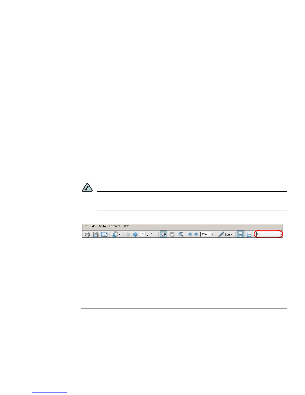
STEP 1 Enter your search terms in the Find text box on the toolbar.
Preface
NOTE By default, the Find tool is available at the right end of the Acrobat toolbar. If
the Find tool does not appear, choose Edit > Find.
STEP 2 Optionally, click the arrow next to the Find text box to refine your search by
choosing special options such as Whole Words Only.
STEP 3 Press Enter.
STEP 4 Acrobat displays the first instance of the search term.
STEP 5 Press Enter again to continue to more instances of the term.
SPA9000 Voice System Installation and Configuration Guide for Web UI x
Page 13
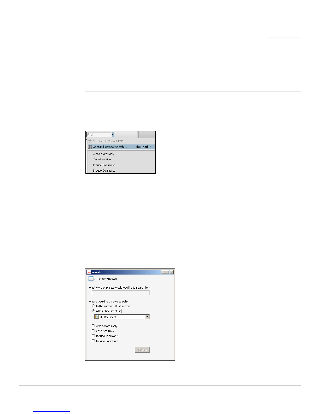
Finding Text in Multiple PDF Files
The
Search
on your PC or local network. The PDF files do not need to be open.
STEP 1 Start Acrobat Professional or Adobe Reader.
window lets you search for terms in multiple PDF files that are stored
Preface
STEP 2 Choose Edit > Search, or click the arrow next to the
Open Full Acrobat Search.
STEP 3 In the
a. Enter the text that you want to find.
b. Choose All PDF Documents in.
c. If you want to specify additional search criteria, click Use Advanced Search
d. Click Search.
Search
From the drop-down box, choose Browse for Location. Then choose the
location on your computer or local network, and click OK.
Options, and choose the options you want.
window, complete the following steps:
Find
box and then choose
SPA9000 Voice System Installation and Configuration Guide for Web UI xi
Page 14

Preface
STEP 4 When the Results appear, click + to open a folder, and then click any link to open
the file where the search terms appear.
For more information about the Find and Search functions, see the Adobe Acrobat
online help.
SPA9000 Voice System Installation and Configuration Guide for Web UI xii
Page 15

Getting Started
This chapter introduces you to the SPA9000 Voice System by describing the
components and presenting several deployment scenarios.
NOTE This chapter is essential reading before you begin installing the equipment or
configuring the system.
1
• “Introduction to the SPA9000 Voice System,” on page13
• “Deployment Scenarios,” on page15
• “Introducing Components of the SPA9000 Voice System,” on page 20
Introduction to the SPA9000 Voice System
The SPA9000 Voice System is an affordable and feature-rich IP telephone system
that is designed especially for the Small and Home Office. The SPA9000 Voice
System uses standard TCP/IP protocols and can provide global connectivity
through any Internet Telephony Service Provider (ITSP) that supports the Session
Initiation Protocol (SIP).
At minimum, the SPA9000 Voice System includes a SPA9000 IP PBX and one or
more SPA900 series IP phones. These devices are connected through a switch to
a local area network. With an Internet connection, the SPA9000 Voice System can
subscribe to ITSP services to take advantage of low calling rates. With the
SPA400, the SPA9000 Voice System can connect to the Public Switched
Telephone Network (PSTN) to support analog phone lines. See Figure 1 “SPA9000
Voice System with the SPA9000 and SPA400” on page14 to learn more about a
typical deployment.
SPA9000 Voice System Installation and Configuration Guide for Web UI 13
Page 16
Getting Started
Introduction to the SPA9000 Voice System
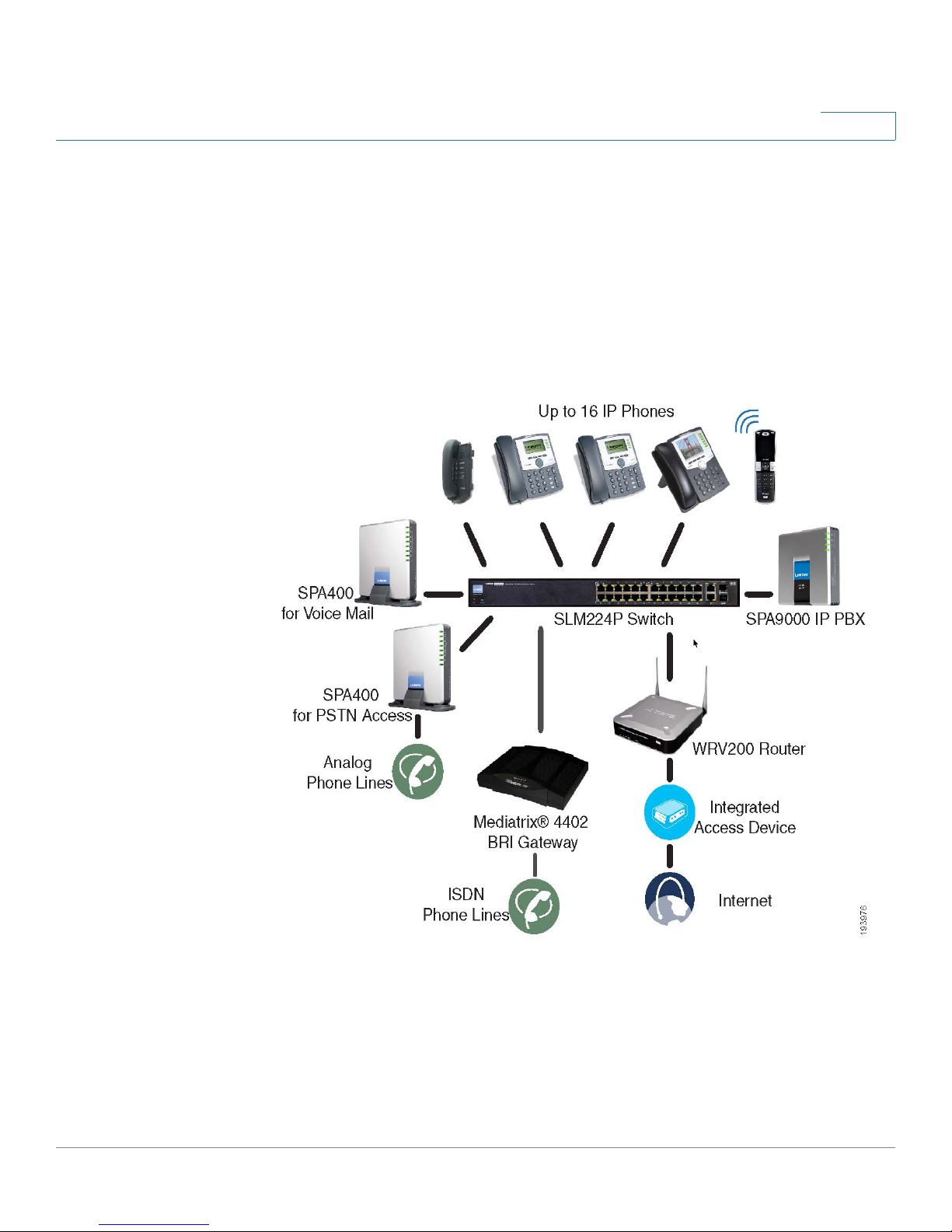
Figure1 SPA9000 Voice System with the SPA9000 and SPA400
1
SPA9000 IP PBX
The SPA9000 is an IP PBX that supports up to 16 phones. It also has a built-in
Analog Telephone Adapter (ATA) with two FXS ports for analog telephones, fax
devices, or an external music source for the music on-hold service. Devices
connected to the FXS ports are not included in the device count.
The SPA9000 has four line interfaces, which can be configured in any combination
for ITSP service, ISDN access, SPA400 PSTN access, or SPA400 voice mail
service. A different ITSP account can be configured on each line interface. If a
service provider supplies a group of sequential direct inward dial (DID) phone
numbers (such as 408-555-0100 through 555-0145) the SPA9000 can support all
of the assigned numbers on a single line interface.
SPA9000 Voice System Installation and Configuration Guide for Web UI 14
Page 17

Getting Started
Deployment Scenarios
1
The SPA9000 includes an Auto Attendant service that plays pre-recorded voice
messages to offer the caller a menu of choices and to direct the call. When the
Auto-Attendant is enabled, it parses and operates on user key presses according
to the rules that are specified in the Auto Attendant script.
SPA400 SIP-PSTN Gateway and Voicemail Server
The SPA400 provides a SIP-PSTN gateway for voice connectivity between the
PSTN and the local client stations that are connected to the SPA9000. It also
includes an integrated voice mail application that supports up to 32 voice mail
accounts with customized greetings, providing the ability to receive and playback
voice mail messages.
Each SPA400 occupies one of the four line interfaces on the SPA9000. The
SPA400 has four ports for that can be connected to PSTN or ISDN lines.
IP Phones and Accessories
The SPA9000 Voice System supports any of the Cisco SPA900 Series SIP IP
Phones, as well as the Cisco WIP310 Wireless IP Phone.
NOTE This guide explains how to configure the SPA9000 and the SPA400 to support the
calling features on the phones. For more information about the phones, see the
SPA9x2 Phone Administration Guide, the SPA9x2 Phone User Guide, and the
Cisco Wireless-G IP Phone User Guide.
Deployment Scenarios
The SPA9000 Voice System can meet the calling needs of many small businesses.
Various deployment scenarios are possible. This section includes the following
examples:
• “PSTN Access and Local Voice Mail,” on page16
• “ITSP Service Only,” on page17
• “ITSP Service, PSTN Access and Local Voice Mail,” on page18
• “ITSP Service, PSTN and ISDN Access and Local Voice Mail,” on page19
SPA9000 Voice System Installation and Configuration Guide for Web UI 15
Page 18
Getting Started
Deployment Scenarios
1
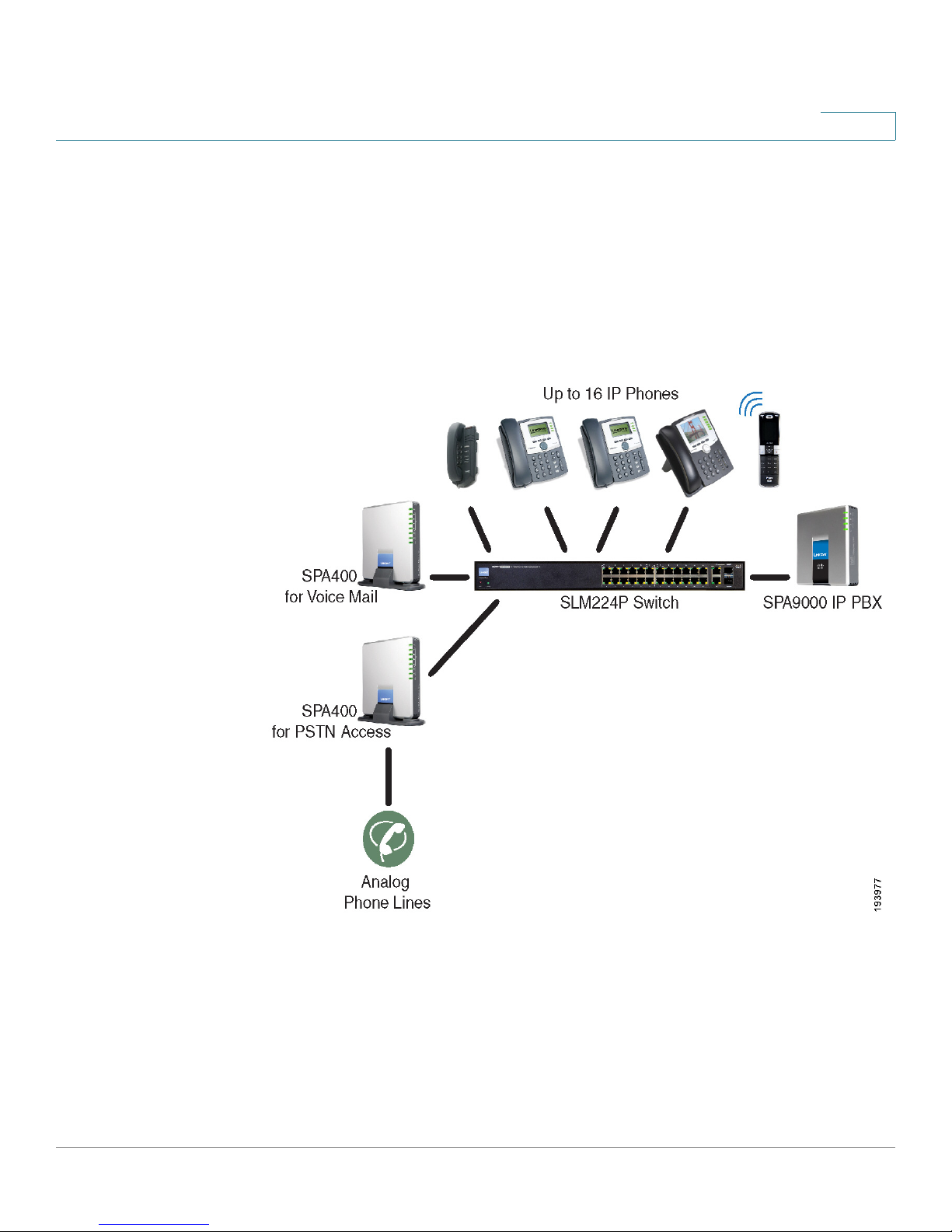
PSTN Access and Local Voice Mail
In this scenario, the customer requires a robust phone system but is not using VoIP
services. The SPA9000 Voice System is deployed with a SPA9000 IP PBX, one
SPA400 for PSTN access with four FXO ports, and another SPA400 for local voice
mail service. Up to 16 IP phones can be installed. Optionally, analog phones or fax
machines (not illustrated) can be connected to the two phone ports on the
SPA9000.
SPA9000 Voice System Installation and Configuration Guide for Web UI 16
Page 19
Getting Started
Deployment Scenarios
1
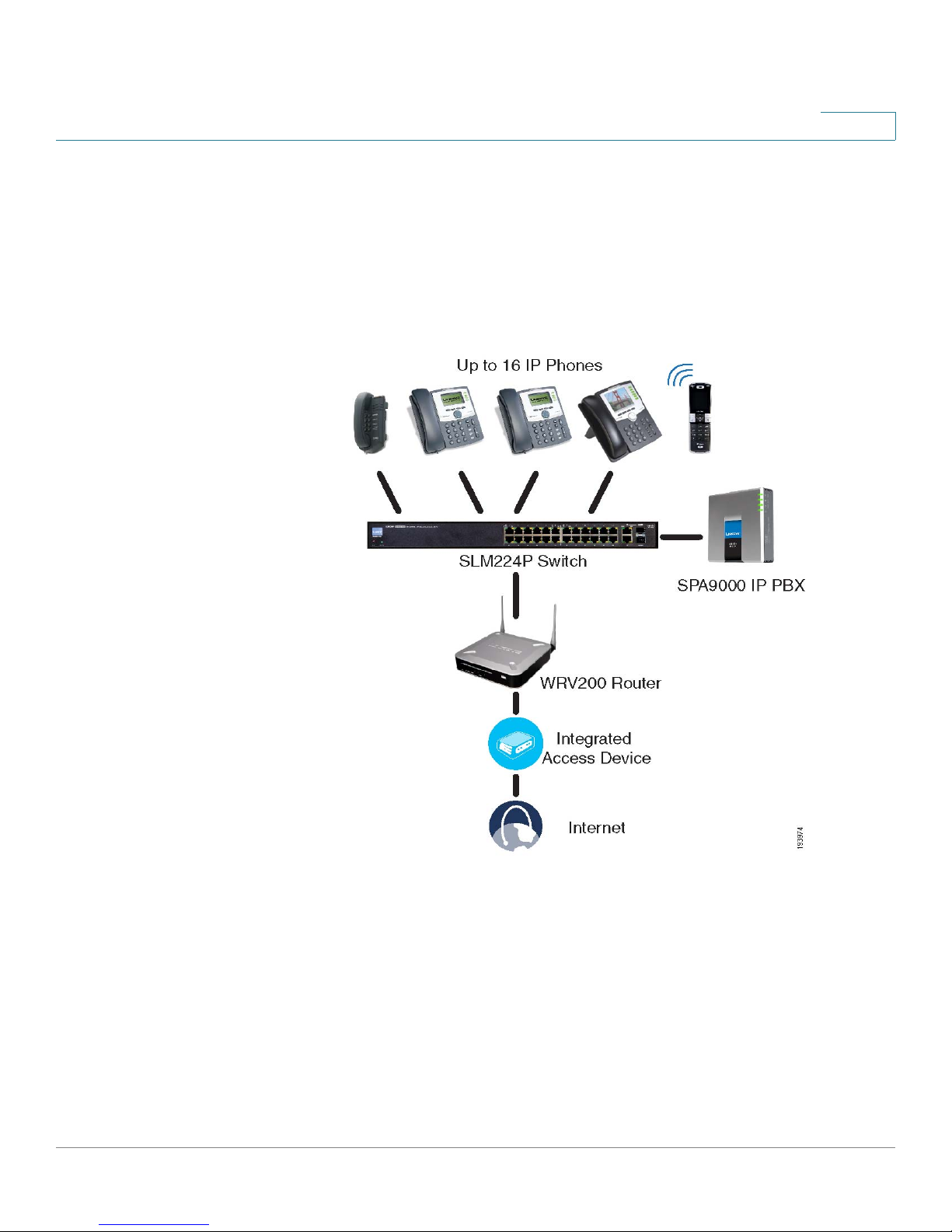
ITSP Service Only
In this scenario, a customer has no legacy telephone numbers and either needs no
voice mail at all or has voice mail hosted by the ITSP. The SPA9000 Voice System
is deployed with the SPA9000 IP PB and VoIP service. Up to 16 IP phones can be
installed. Optionally, analog phones or fax machines (not illustrated) can be
connected to the two phone ports on the SPA9000.
SPA9000 Voice System Installation and Configuration Guide for Web UI 17
Page 20
Getting Started
Deployment Scenarios
1
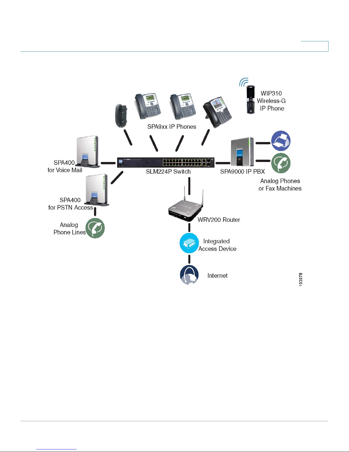
ITSP Service, PSTN Access and Local Voice Mail
In this scenario, the customer wants to use ITSP service for reduced long distance
fees but needs to support legacy local telephone numbers (for example, to receive
calls to a legacy telephone number or to place outbound calls in the local area).
This customer also prefers local voice mail service. The SPA9000 Voice System is
deployed with the SPA9000 IP PBX, VoIP service, one SPA400 unit for voice mail
service, and another SPA400 unit for PSTN access with four FXO ports. Up to 16 IP
phones can be installed. Optionally, analog phones or fax machines (not illustrated)
can be connected to the two phone ports on the SPA9000.
SPA9000 Voice System Installation and Configuration Guide for Web UI 18
Page 21
Getting Started
Deployment Scenarios
1
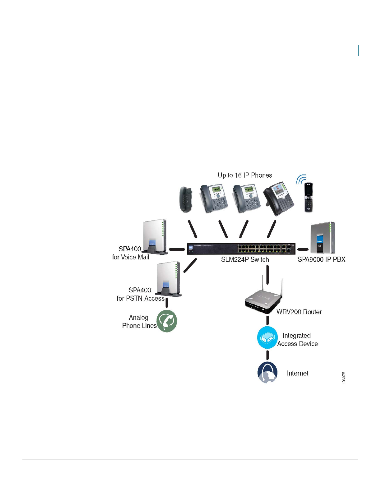
ITSP Service, PSTN and ISDN Access and Local Voice Mail
In this scenario, the customer takes full advantage of the SPA9000 Voice System
solution. This customer has the SPA9000 IP PBX, VoIP service, one SPA400 unit for
voice mail service, and another SPA400 for PSTN access with four FXO ports. In
addition, this installation includes an ISDN Gateway for ISDN BRI access with four
BRI ports. Up to 16 IP phones can be installed. Optionally, analog phones or fax
machines (not illustrated) can be connected to the two phone ports on the
SPA9000.
SPA9000 Voice System Installation and Configuration Guide for Web UI 19
Page 22
Getting Started
Introducing Components of the SPA9000 Voice System
Introducing Components of the SPA9000 Voice System
This section describes the features of the components of the SPA9000 Voice
System, including the SPA9000, the SPA400, and the various models of SPA9xx
phones.
• “Getting to Know Your SPA9000,” on page 20
• “Getting to Know Your SPA400,” on page 22
• “Getting to Know Your IP Phones and Accessories,” on page 24
• “Getting to Know Your WRV200 Router,” on page 26
• “Getting to Know the SLM224P Switch,” on page 28
1
Getting to Know Your SPA9000
The SPA9000 is an IP PBX system with high-end features comparable to
traditional large business voice services. This section describes the LEDs on the
front panel and the ports on the back panel of the device.
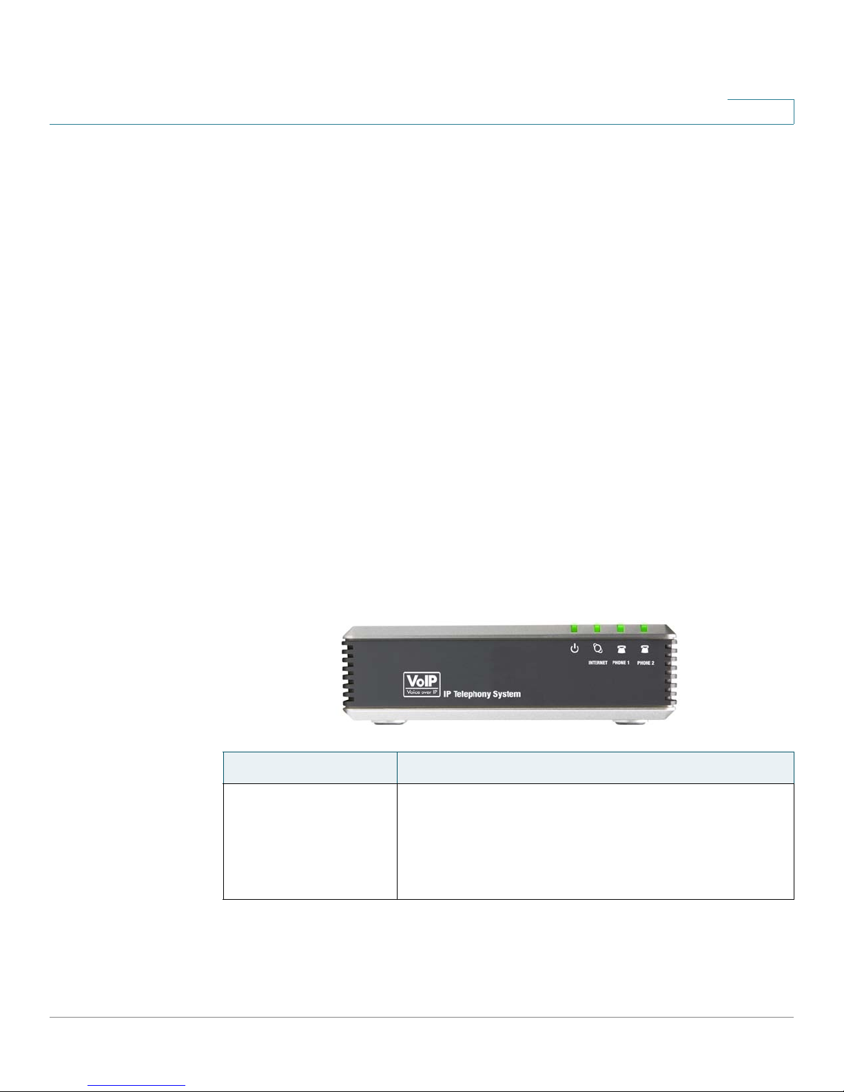
SPA9000 Front Panel
LED Description/Notes
POWER
• Green: The device is receiving power and is connected
to the Internet.
• Flashing Green: The device is receiving power but is not
connected to the Internet.
SPA9000 Voice System Installation and Configuration Guide for Web UI 20
• Unlit: The device is not receiving power.
Page 23
Getting Started
Introducing Components of the SPA9000 Voice System
LED Description/Notes
1
INTERNET
PHONE 1, PHONE 2
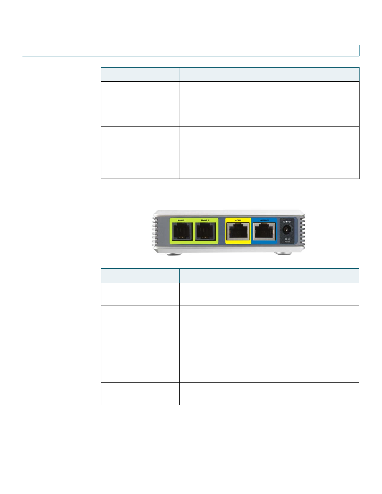
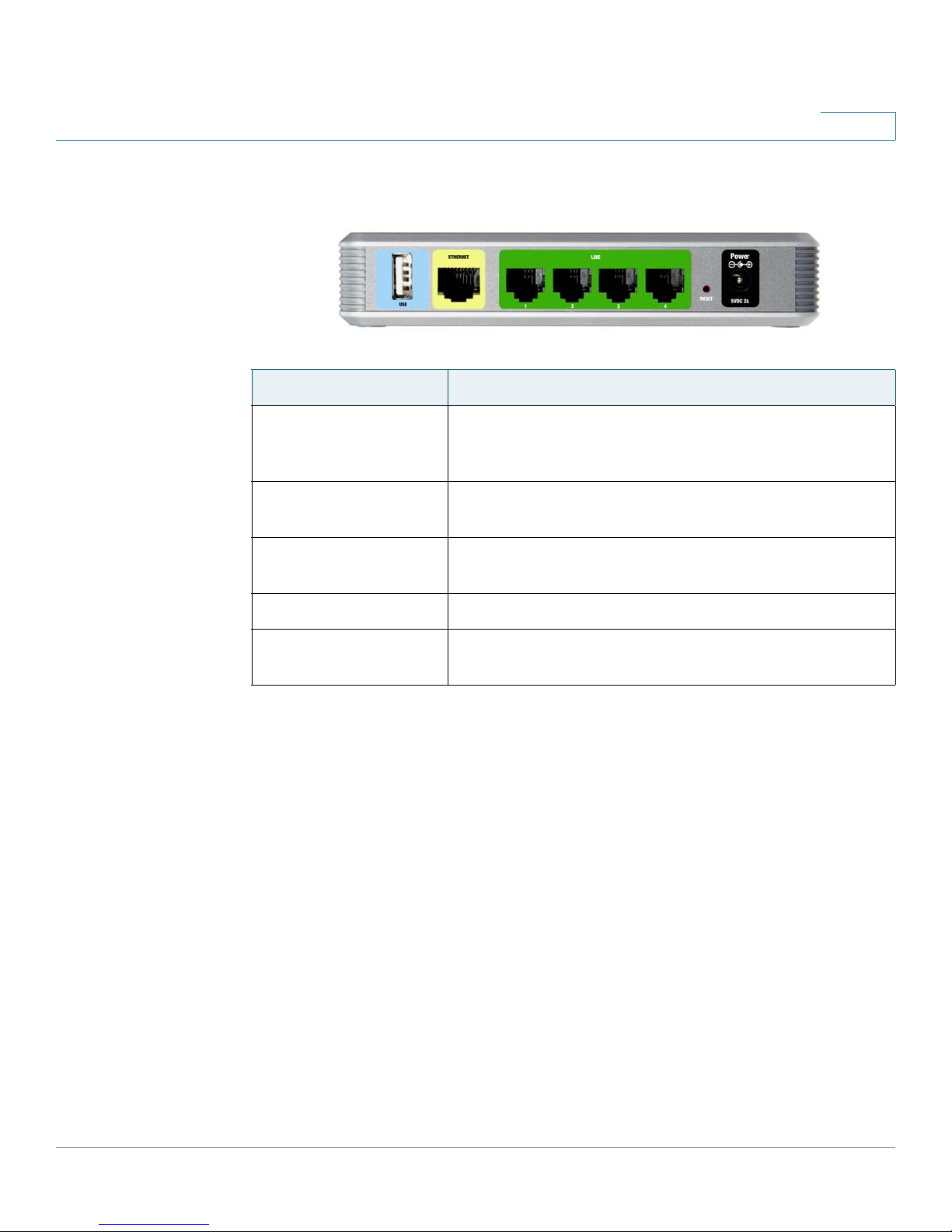
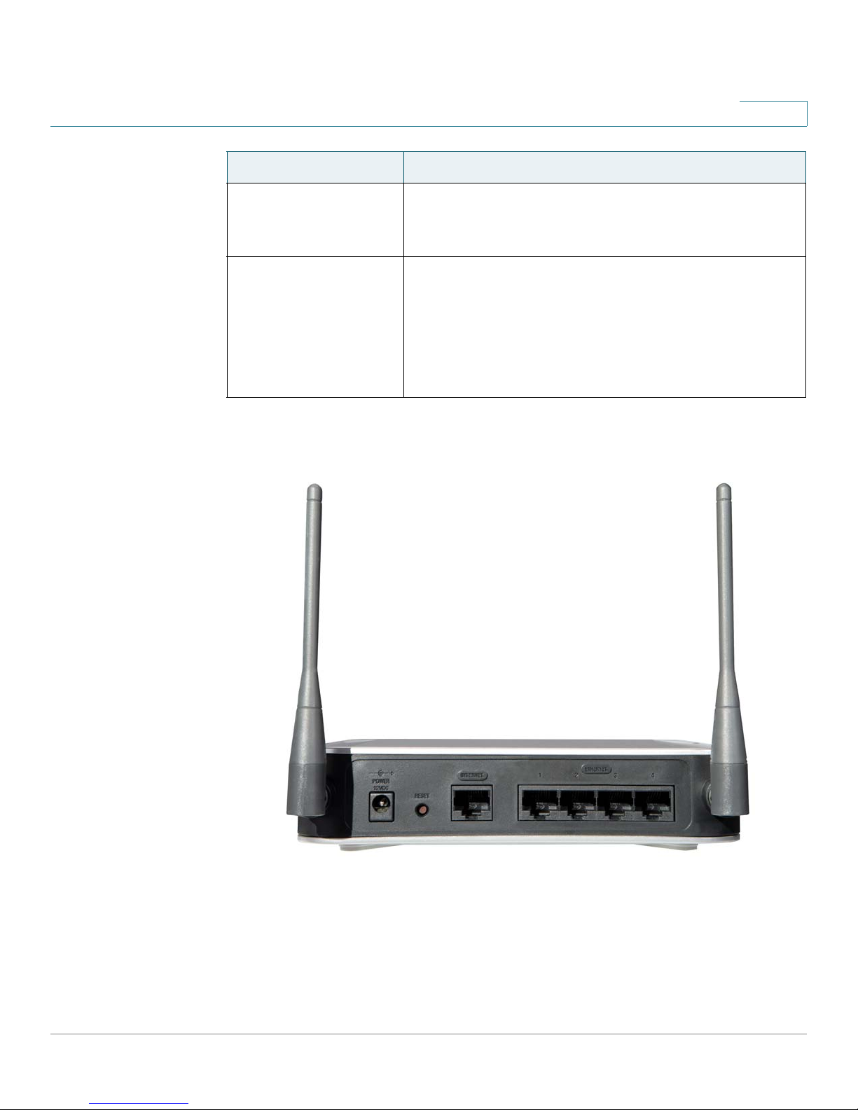
SPA9000 Back Panel
• Green: The device is connected to the Internet.
• Flashing Green: The device is experiencing network
activity.
• Unlit: The device is not connected to the Internet.
• Green: The phone is on hook and is registered with an
active Internet phone service account.
• Unlit: The phone is on hook but is not registered with an
active Internet phone service account.
• Flashing Green: The phone is off hook.
Port Description/Notes
PHONE 1, PHONE 2 Use these ports to connect analog phones or fax
machines to your IP phone account.
ETHERNET The use of this port is deprecated. You can use it for
direct connection of an administration computer, but
the recommended best practice is connect your
administration computer to a LAN switch that is
connected to the SPA9000’s INTERNET port.
INTERNET Use this port to connect the SPA9000 to the Local Area
Network (LAN). The cable may be connected to a
switch, router or Integrated Access Device.
POWER Use this port to connect to the external Power adapter
(PA100).
SPA9000 Voice System Installation and Configuration Guide for Web UI 21
Page 24
Getting Started
Introducing Components of the SPA9000 Voice System
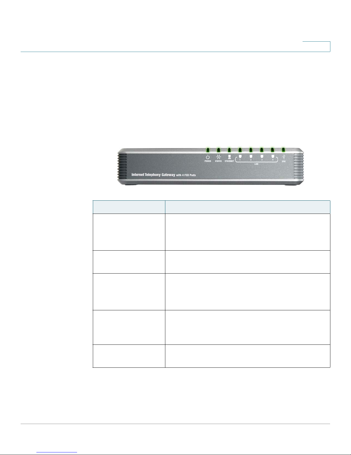
Getting to Know Your SPA400
The SPA400 provides the SPA9000 access to the PSTN by connecting the FXO
ports to analog lines. The SPA400 also has a built-in voice mail server.
This section describes the LEDs on the front panel and the ports on the back panel
of the device.
SPA400 Front Panel
1
LED Description/Notes
POWER
• Steady green: The SPA400 is receiving power and is
connected to the Internet.
• Flashing: The SPA400 is not connected to the Internet,
booting, or upgrading firmware.
STATUS
• Steady green: The SPA9000 is registered to the SPA400.
• Flashing: The SPA9000 is not registered to the SPA400.
ETHERNET
• Steady green: The SPA400 has an active connection
through the Ethernet port.
• Flashing: Network activity is occurring over the
ETHERNET port.
LINE 1, 2, 3, 4
• Steady green: The line is active.
• Flashing: The line is ringing.
• Off: The line is idle.
USB
• Steady green: The USB voice mail module is registered.
• Off: No module is detected.
SPA9000 Voice System Installation and Configuration Guide for Web UI 22
Page 25
Getting Started
Introducing Components of the SPA9000 Voice System
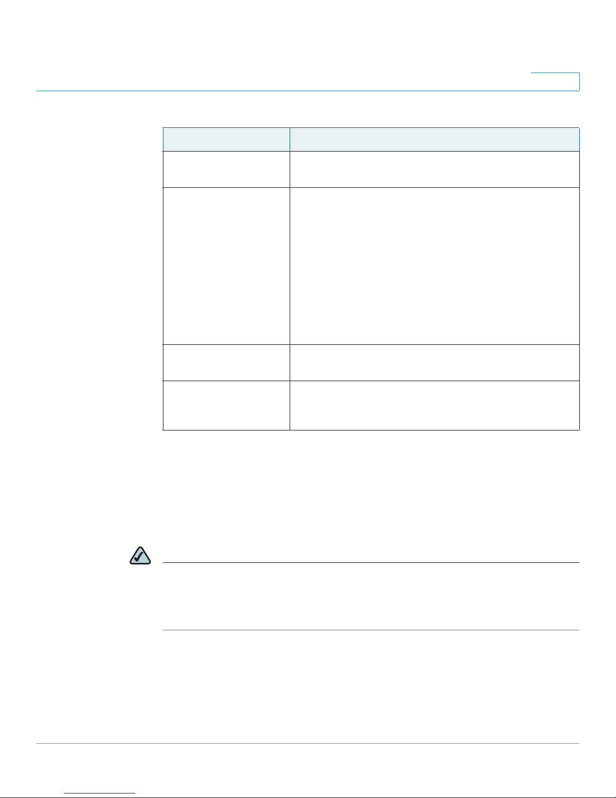
SPA400 Back Panel
Port Description/Notes
USB Use this port for the USB voice mail module, which
ETHERNET Use this port to connect to the Local Area Network
1
contains the voice mail prompts and provides the
storage location for saving voice mailbox messages.
(LAN) for communications with SPA9000.
LINE 1, 2, 3, 4 These FXO ports are used to connect to an analog
phone lines.
RESET This button is used to reset the device.
POWER Use this port to connect to the external Power adapter
(PA100).
SPA9000 Voice System Installation and Configuration Guide for Web UI 23
Page 26
Getting Started
Introducing Components of the SPA9000 Voice System
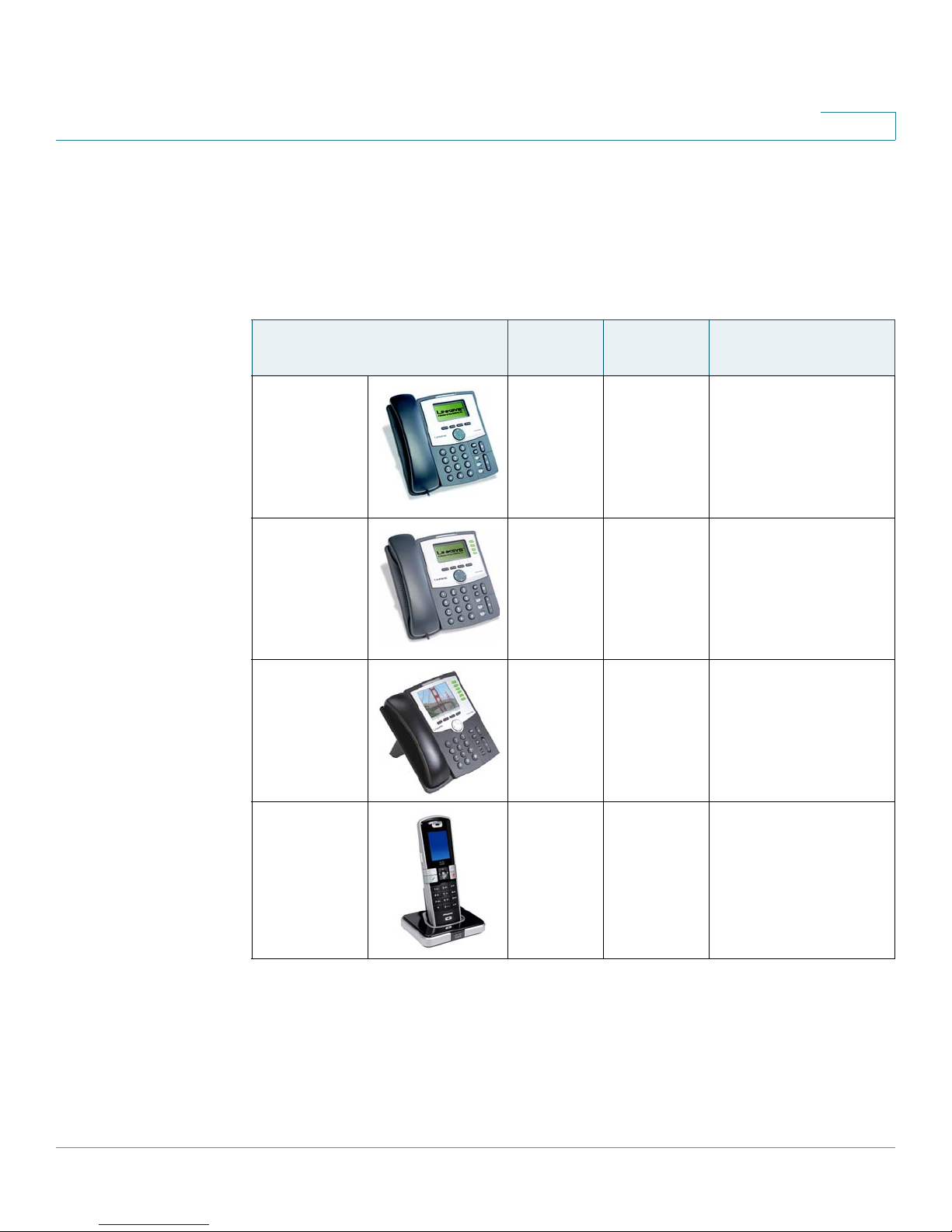
Getting to Know Your IP Phones and Accessories
Cisco provides a variety of phone models to suit the needs of small businesses.
The following table provides a comparison of Cisco IP phones and accessories
that can be used with the SPA9000 Voice System.
1
Product RJ-45 Voice
Lines
SPA922* 2 1 One-line IP phone
SPA942* 2 4 Four-line IP phone
SPA962* 2 6 Six-line IP Phone
Additional
Features/Notes
with Power over
Ethernet (PoE)
support
with Power over
Ethernet (PoE)
support
with high-resolution
color display and
Power over Ethernet
(PoE) support
WIP310 N/A 1 Wireless-G IP phone
SPA9000 Voice System Installation and Configuration Guide for Web UI 24
Page 27
Getting Started
Introducing Components of the SPA9000 Voice System
1
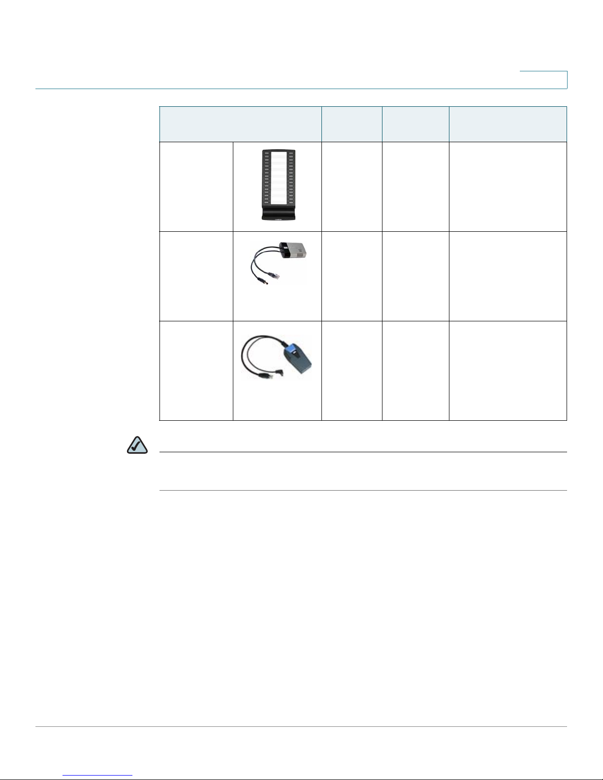
Product RJ-45 Voice
Lines
SPA932 — — Attendant console
POES5 1 N/A Provides an 802.3af
WBP54G 1 N/A Converts your IP
Additional
Features/Notes
(sidecar) for SPA962
with 32 buttons and
LEDs for monitoring
and call transfer
PoE port for
connection back to a
PoE switch for
SPA9000 and
SPA400
phone into a wireless
device, so it can
connect to your
wireless network
without an Ethernet
cable
NOTE * SPA922/942/962 do not include an external power adapter. If you are using a non-
PoE switch, a PA100 power adapter is required.
SPA9000 Voice System Installation and Configuration Guide for Web UI 25
Page 28
Getting Started
Introducing Components of the SPA9000 Voice System
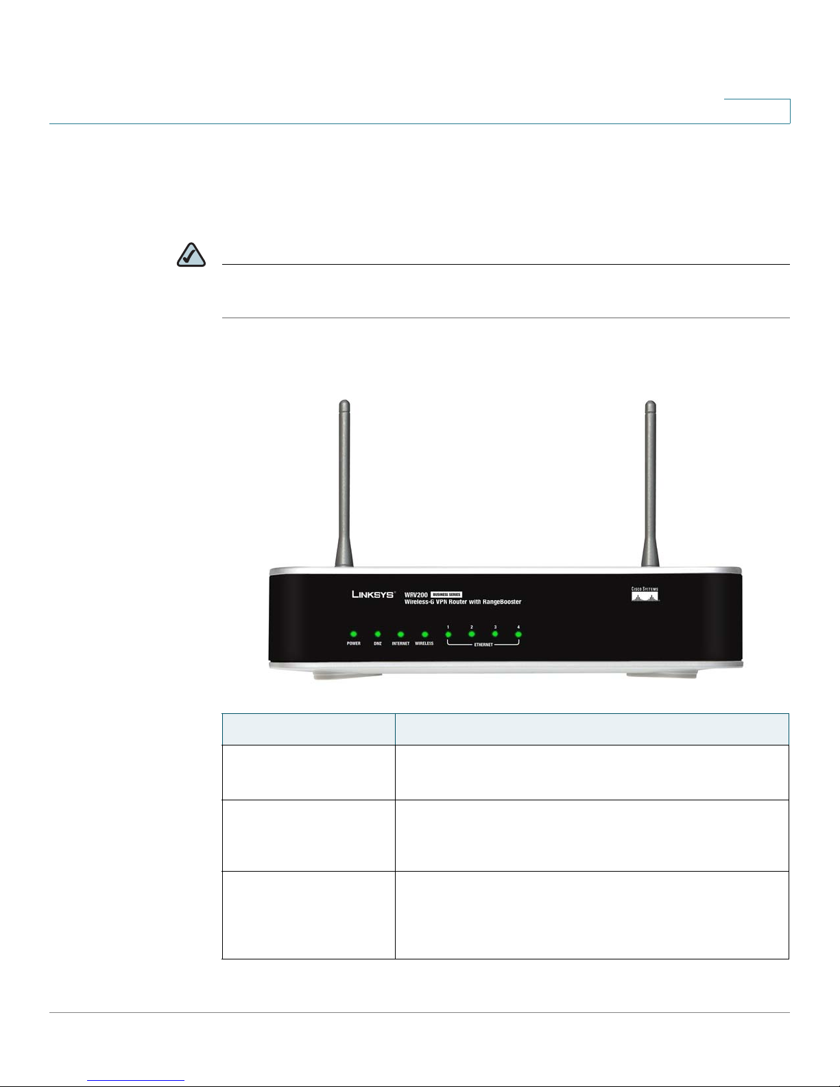
Getting to Know Your WRV200 Router
WRV200 is a VPN router with a Wireless-G access point for small offices and
home offices. It is strongly recommended for use with the SPA9000 Voice System.
NOTE A Wireless-G router is required if you are using wireless components such as the
WIP310 telephone.
WRV200 Front Panel
1
LED/Port Description
POWER
DMZ
INTERNET
SPA9000 Voice System Installation and Configuration Guide for Web UI 26
• Green: The router is receiving power.
• Flashing Green: The router is running a diagnostic test.
• Green: The router has an available DMZ port.
• Flashing Green: The router is sending or receiving data
over the DMZ port.
• Green: The router is connected to a Broadband Access
device at the indicated speed (10, 100, 1000).
• Flashing Green: The router is transmitting or receiving
data over the INTERNET port.
Page 29
Getting Started
Introducing Components of the SPA9000 Voice System
LED/Port Description
1
Wireless
• Green: The router has a successful wireless connection.
• Flashing Green: The Router is actively sending or
receiving data over the wireless network.
1-4 (Ethernet) These four LEDs correspond to the router’s four
Ethernet ports.
• Green: The Router is connected to a device through the
corresponding port (1, 2, 3, or 4).
• Flashing Green: The Router is actively sending or
receiving data over the corresponding port.
WRV200 Back Panel
SPA9000 Voice System Installation and Configuration Guide for Web UI 27
Page 30
Getting Started
Introducing Components of the SPA9000 Voice System
LED/Port Description
POWER This port is used to connect the router to AC power,
1
using the provided power cable.
RESET
• The Reset button has two functions:
• If the Router is having problems connecting to the
Internet, press the Reset button for just a second with a
paper clip or a pencil tip. This is similar to pressing the
Reset button on your PC to reboot it.
• If you are experiencing extreme problems with the
router and have tried all other troubleshooting measures,
press and hold in the Reset button for 10 seconds. This
action restores the factory defaults and clears all of the
Router’s settings, such as port forwarding or a new
password.
INTERNET Use this port to connect the router to a Broadband
Access device.
1-4 (Ethernet) Use these ports to connect the router to network
devices, such as PCs, print servers, or additional
switches.
Getting to Know the SLM224P Switch
The SLM224P switch has 24 10/100 Copper ports with two shared Gigabit
copper or optical SFP ports (combo ports) for connecting the switch to the core
network.
NOTE In this guide, the SLM224P switch is used in all examples and illustrations. However,
various Cisco switches can be used with the SPA9000 Voice System. Cisco
recommends use of SLMxxxP, SRWxxxP and SRWxxxMP switch product families
with the SPA9000 Voice System.
SPA9000 Voice System Installation and Configuration Guide for Web UI 28
Page 31

Getting Started
Introducing Components of the SPA9000 Voice System
SLM224P Front Panel
LED/Port Description
1
SYSTEM
LINK/ACT (1-24)
POE (1-6, 13-18)
100M (7-12, 19-24)
LINK/ACT (G1-G2)
• Green: Power is being supplied to the switch.
• Solid Amber: The switch is performing the Power-On
Self Test (POST).
• Green: The switch has a functional 10/100 Mbps
network link through the corresponding port with an
attached device.
• Flashing: The switch is actively sending or receiving data
over the corresponding port.
• Flashing Amber: Power is being supplied to an attached
powered device (PD) on the corresponding port (1
through 6, 13 through 18).
• Amber: The switch has a functional 100 Mbps
connection on the corresponding port (7 through 12, 19
through 24) with an attached device.
• Green: Lights up to indicate a functional 10/100/1000
Mbps network link through the corresponding port (G1
through G2) with an attached device.
• Flashing Green: The switch is actively sending or
receiving data over the corresponding port.
GIGABIT (G1-G2)
RESET
SPA9000 Voice System Installation and Configuration Guide for Web UI 29
• Amber: The switch has a functional 1000 Mbps
connection on the corresponding port with an attached
device.
• To reboot the switch, press and hold the Reset button for
approximately five seconds.
• To reset the Switch settings to the factory defaults,
press and hold the Reset Button for approximately ten
seconds.
Page 32

Getting Started
Introducing Components of the SPA9000 Voice System
LED/Port Description
ETHERNET (1-24) The Switch is equipped with 24 auto-sensing, Ethernet
G1-G2 The switch is equipped with 2 auto-sensing 10 Mbps,
1
network ports, which use RJ-45 connectors. The Fast
Ethernet ports support network speeds of 10 Mbps,
100 Mbps, or 1000 Mbps. They can operate in halfand full-duplex modes. Auto-sensing technology
enables each port to automatically detect the speed of
the device connected to it (10 Mbps, 100 Mbps, or
1000 Mbps), and adjust its speed and duplex
accordingly.
100 Mbps, or 1000 Mbps Gigabit Ethernet network
ports, which use RJ-45 connectors. They can operate
in half- and full-duplex modes.
mini-GBIC (1-2) The mini-GBIC (gigabit interface converter) port is a
connection point for a mini-GBIC expansion module, so
the switch can be uplinked via fiber to another switch.
SLM224P Back Panel
The back panel has one port, the Power port, which is used to connect the power
cord.
SPA9000 Voice System Installation and Configuration Guide for Web UI 30
Page 33

Installation and Configuration Process
Overview
This chapter provides an overview of the installation and configuration process.
A. Preparation
2
In Chapter 3, “Preparation,” you learn about the equipment and service
requirements, bandwidth requirements, call capacity, and related topics , to ensure
that the system is well designed to meet the needs of the customer. This chapter
also describes basic procedures such as downloading firmware, which should be
completed before you begin installing the equipment.
B. Connecting the Equipment
In this phase, you physically connect the SPA9000 Voice System equipment to the
LAN. Chapter 4, “Connecting the Equipment” explains how to connect the
SPA9000, which provides the PBX service for the phones, and the SPA400, which
provides voice mail service and PSTN access. You also learn how to install the IP
phones and any accessories such as PoE adapters and wall-mount brackets. You
also upgrade the firmware with the new files that you downloaded during the
Preparation phase.
C. Configuring Voice Services
After you connect the equipment, you need to configure voice features such as
ITSP service, PSTN access, and voice mail service.Chapter 5, “Configuring
Phone Service and Voice Mail” guides you through these steps. You also set up
call routing for outbound and inbound calls.
SPA9000 Voice System Installation and Configuration Guide for Web UI 31
Page 34

Installation and Configuration Process Overview
D. Configuring Advanced Features
D. Configuring Advanced Features
Now you are ready to begin configuring advanced features, depending on the
business needs. In Chapter 6, “Configuring Special Features,” you learn how to
configure Music On Hold, to set up the SPA962 phone with the SPA932 attendant
console, and to route calls with hunt groups and shared line appearances.
E. Localizing the System
For customers outside North America, you need to localize the system. Chapter 7,
“Localization,” guides you through the steps.
2
SPA9000 Voice System Installation and Configuration Guide for Web UI 32
Page 35

Preparation
This chapter is essential reading before you begin installing the equipment or
configuring the system. To ensure that the installation process goes smoothly,
verify that you have the required services, equipment, and information.
Refer to the following topics:
• “Site Survey,” on page 33
3
Site Survey
• “System Design Considerations,” on page 34
• “Network Setup Review,” on page 36
• “Quality of Service,” on page 38
• “Local Area Network Design,” on page 38
• “Services and Equipment,” on page 39
The site surveys consists of gathering relevant information about the customer, the
existing infrastructure, the network, the telephone equipment, and the available
services. This survey helps you to prepare for the installation of the SPA9000
Voice System (for example, ordering the Cisco SPA devices from the distribution
channel) and to anticipate the design considerations. The site survey can be
conducted on the customer premises or remotely over the phone and email.
Various site survey templates can be used. Appendix A, “Installation Workbook,”
contains a site survey template example that you can use to record the customer
information.
SPA9000 Voice System Installation and Configuration Guide for Web UI 33
Page 36

Preparation
System Design Considerations
System Design Considerations
When installing and configuring the SPA9000 Voice System, it is necessary to
analyze and meet some design considerations to ensure the best quality and user
experience. The design considerations cover available bandwidth and quality of
service.
Bandwidth Requirements and Call Capacity
The available connection bandwidth determines the maximum number of
simultaneous calls that the system can support with the appropriate audio quality.
Before installing and configuring the Cisco SPA devices, use this information to
determine the maximum number of simultaneous VoIP connections that the
system can support. For asymmetric connections, such as ADSL, the maximum
number of calls is determined by the upstream bandwidth. In general it is a good
practice to use no more than 75% of the total available bandwidth for calls. This
provides space for data traffic and helps ensure good voice quality.
3
NOTE Some ITSP SIP trunk services limit the maximum number of simultaneous calls.
Please check with your Service Provider to understand the maximum number of
simultaneous calls each SIP trunk supports.
The following table provides the approximate bandwidth budget for different
codecs.
Codec Approximate bandwidth
budget for each side of
conversation
G.711 110 kbps 220
G.726-4087 kbps 174
G.726-3279 kbps 158
G.726-2471 kbps 142
2 calls 4 calls 6 calls 8 calls
kbps
kbps
kbps
kbps
440
kbps
348
kbps
316
kbps
284
kbps
660
kbps
522
kbps
474
kbps
426
kbps
880
kbps
696
kbps
632
kbps
568
kbps
SPA9000 Voice System Installation and Configuration Guide for Web UI 34
Page 37

Preparation
System Design Considerations
3
Codec Approximate bandwidth
budget for each side of
conversation
G.726-1663 kbps 126
G.729 55 kbps 110
For more information about bandwidth calculation, refer to the following web sites:
www.erlang.com/calculator/lipb/
www.bandcalc.com/
2 calls 4 calls 6 calls 8 calls
kbps
kbps
252
kbps
220
kbps
378
kbps
330
kbps
504
kbps
440
kbps
Wide Area Network (WAN) Quality of Service
You can choose from several types of broadband access technologies to provide
symmetric or asymmetric connectivity to a small business. These technologies
vary on the available bandwidth and on the quality of service. It is generally
recommended that you use broadband access with a Service Level Agreement
that provides quality of service. If there is not a Service Level Agreement with
regard to the broadband connection quality of service, the downstream audio
quality may be affected negatively under heavy load conditions (bandwidth
utilization beyond 80%).
To eliminate or minimize this effect, Cisco recommends one of the following
actions:
• For broadband connections with a bandwidth lower than 2 Mbps, perform the
call capacity calculations by assuming a bandwidth value of 50% of the
existing broadband bandwidth. For example, in the case of a 2 Mbps uplink
broadband connection, assume 1 Mbps. Limit the uplink bandwidth in the
Integrated Access Device to this value. This setting helps to maintain the
utilization levels below 60%, thus reducing jitter and packet loss.
• Use an additional broadband connection for voice services only. A separate
connection is required when the broadband connection services do not offer
quality of service and when it is not possible to apply the above mentioned
utilization mechanism.
SPA9000 Voice System Installation and Configuration Guide for Web UI 35
Page 38

Preparation
Network Setup Review
Network Setup Review
The Local Area Network (LAN) is the communication platform used by the
SPA9000 Voice System for allowing communications among the telephone users
and between the telephone users and the external VoIP, PSTN or/and ISDN
network services. This LAN is composed of the data wiring (UTP cabling),
networking equipment (switches and routers/access device) and the
telecommunication (PSTN or ISDN) lines.
The Local Area Network (LAN) may be already installed or it can be installed and
configured at the time of installing the SPA9000 Voice System. Below are the
general recommendations to ensure proper operation of the SPA9000 Voice
System.
Infrastructure, Cabling and PSTN/ISDN Lines
3
•
AC outlets: Ensure there is an AC outlet available for every LAN and Cisco SPA
component that requires AC power. If you are using a Power over Ethernet
switch, SPA9x2 phones do not require an AC outlet as they are powered by the
switch.
• Ethernet cabling: Ensure there is a Ethernet cabling system and that there is an
outlet for each Cisco SPA device. It is recommended that Ethernet cables are
UTP CAT 5e or better.
• PSTN and ISDN lines: Ensure that the lines are operative and that any features,
such as caller identification, operate properly before starting the installation.
Ensure that the cables are available in the location where you are installing the
Cisco SPA devices.
• UPS: If you are using an Uninterrupted Power Supply (UPS) mechanism, ensure
that the SPA9000 Voice System design is covered by securing the router and
switch AC connections and the Cisco SPA devices and by using the Power
over Ethernet adapter (POES5) for the non-POE products (SPA9000, SPA400,
SPA9x1 phones). Also ensure that devices such as the WAN modem, CSU/
DSU, or DDS modem are connected to the UPS.
SPA9000 Voice System Installation and Configuration Guide for Web UI 36
Page 39

Preparation
Network Setup Review
3
NAT Mapping
Network Address Translation (NAT) is a function that allows multiple devices to
share the same public, routable, IP address to establish connections over the
Internet. NAT is present in many broadband access devices to translate public and
private IP addresses. To enable VoIP to co-exist with NAT, some form of NAT
traversal is required.
Some ITSPs provide NAT traversal, but some do not. If your ITSP does not provide
NAT traversal, you have several options.
• NAT mapping with SIP-ALG router: Use a router such as the WRV200, which
has a SIP ALG (Application Layer Gateway). With a SIP ALG in the router, you
have more choices in selecting an ITSP.
• ITSP that supports NAT mapping through a Session Border Controller: With
NAT mapping provided by the ITSP, you have more choices in selecting a
router.
• NAT mapping with the SPA9000 EXT IP setting: Configuring NAT mapping in
the SPA9000 is recommended only if the ITSP network does not provide a
Session Border Controller functionality. If this is the case, and if the external
(public) IP address is static, then Cisco recommends mapping a static
(permanent) IP address on the SPA9000. Instructions are available in the
SPA9000 Voice System Administration Guide
.
• Configuring NAT Mapping with Simple Traversal of UDP through NAT (STUN):
Configuring NAT mapping in the SPA9000 is recommended only if the ITSP
network does not provide a Session Border Controller functionality. If this is the
case, and if the external (Public) IP address is assigned dynamically by the
network (and the router uses asymmetric NAT mechanism), it is possible to use
STUN as a mechanism to discover the NAT mapping in SPA9000. This method
is considered a practice of last resort and should be used only if the other
methods are unavailable. For more information, see the
Administration Guide
.
SPA9000 Voice System
SPA9000 Voice System Installation and Configuration Guide for Web UI 37
Page 40

Preparation
Quality of Service
Quality of Service
Cisco recommends using the SPA9000 Voice System with QoS-capable
networking equipment that can prioritize the VoIP application traffic. QoS features
are available on many Cisco data networking switches (such as the SLM224P) and
routers (such as WRV200). A QoS-enabled router prioritizes the packets going
upstream to the Internet Service Provider. QoS can be enforced using either DSCP
(Diffserv Codepoint) ToS (Type of Service) or 802.1 Q/p VLAN ID and priority
setting. DSCP ToS is recommended for its simplified setup.
Instructions for the SLM224P are provided in this guide.
Local Area Network Design
3
Use the following guidelines to manage the LAN setup for the SPA9000 Voice
System.
• Ensure that all Cisco SPA devices are located in the same local area network
subnet.
• Although all Cisco SPA devices support static IP addressing, we recommend
using a DHCP server to add IP telephones to the system. Ensure that the DHCP
server can assign enough IP addresses to serve the Cisco IP phones and the
existing networked components such as PCs, servers, and so on.
• If you are using DHCP, use a long lease time. Cisco IP phones may reboot on the
event of an IP address change because of lease time expiration.
• Use stable DNS server addresses for URL name resolution. Your Internet
Service Provider can provide the primary and secondary DNS server IP
addresses.
SPA9000 Voice System Installation and Configuration Guide for Web UI 38
Page 41

Preparation
Services and Equipment
Services and Equipment
To install and configure SPA9000 Voice System, you need the following services
and equipment.
Basic Services and Equipment
The following basic services and equipment are required:
• An Integrated access device or modem for broadband access to the Internet;
business grade account recommended
• Internet Telephony Service Provider (ITSP) for Voice Over IP telephone service,
supporting a “bring your own device” model
You must have at least the following information about your account:
3
• SIP Proxy (IP address or name)
• Account Information and Password
• Computer with Microsoft Windows XP or Windows Vista (for system
configuration)
• Analog phone for administrative use with the SPA9000 Interactive Voice
Response (IVR) system
• Uninterruptible Power Source (UPS), recommended for devices such as the
Integrated Access Device, network switch, router, and PoE switch to ensure
continuous operation during a power failure
Cisco Equipment and Services
The following Cisco equipment is recommended:
• SPA9000 IP PBX
One SPA9000 unit is required for IP PBX features. Only one SPA9000 is
supported.
• SPA400 PSTN Gateway and Voice Mail Server
It is recommended that you install one SPA400 unit exclusively for voice mail
service and one or more additional SPA400 units for PSTN access. Each unit
has four FXO ports and occupies one line interface on the SPA9000. With ITSP
SPA9000 Voice System Installation and Configuration Guide for Web UI 39
Page 42

Preparation
Downloading Firmware
3
service taking one line interface on the SPA9000, up to three SPA400 units can
be installed. With no ITSP service, up to four SPA400 units can be installed.
• SPA9xx series IP phones
The SPA9x1 series phones require access to power outlets. The SPA9x2
series phones can receive power from a Power over Ethernet (PoE) switch and
are not supplied with power supplies. If you are not using the recommended
PoE switch, you need to purchase a suitable power supply or power injector
for the SPA9x2 phones.
• Switch (example: SLM224P)
• Router (example: WRV200)
• Optional POES5 Power over Ethernet adapters, for providing POE-derived
power to non-POE devices such as SPA9000, SPA400 and SPA9x1, in case
UPS is available.
• Optional WBP54G Wireless-G adapter, for providing Wireless client
functionality to IP Phones, if required to connect a phone to the LAN using
Wireless technology.
Downloading Firmware
Cisco recommends that you check for recent updates before you install your
equipment. Later instructions in this guide will help you to install the firmware that
you download in this preparation phase. To find the latest firmware for a device, go
to tools.cisco.com/support/downloads and enter the model number in the
Software Search box. Repeat for each device in your configuration.
SPA9000 Voice System Installation and Configuration Guide for Web UI 40
Page 43

Connecting the Equipment
This chapter explains how to connect your equipment and upgrade the firmware.
At the end of each section, you verify that the installation is progressing correctly.
• “Connecting and Configuring the Switch,” on page 41
• “Installing the SPA9000,” on page 46
• “Installing the IP Phones,” on page 53
4
• “Installing the SPA400,” on page 58
Connecting and Configuring the Switch
Before installing any equipment, you need to connect the SLM224P Ethernet
switch to a network broadband router or Integrated Access Device (IAD). If the site
is not already equipped with another broadband router/IAD, Cisco recommends
the use of the WRV200 broadband router to connect to the access device.
• “Connecting the Switch to the Router,” on page 42
• “Configuring the Switch,” on page 43
NOTE In this guide, the SLM224P switch is used in all examples. However, various Cisco
switches can be used with SPA9000 Voice System. Cisco recommends use of the
SLMxxxP, SRWxxxP and SRWxxxMP switch product families with SPA9000 Voice
System. For more information, visit the following URL:
www.cisco.com/cisco/web/solutions/small_business/products/
routers_switches/index.html
SPA9000 Voice System Installation and Configuration Guide for Web UI 41
Page 44

Connecting the Equipment
Connecting and Configuring the Switch
Connecting the Switch to the Router
In this procedure, you connect the switch to the router and a power source.
4
STEP 1 Connect a network cable to one of the LAN ports on your router. Then connect the
other end of the cable to a LAN port on the switch.
STEP 2 Connect an administrative computer to an Ethernet port on the switch. The PC
needs to have an IP address on the same network as the switch, which has a
default IP address of 192.168.1.254.
STEP 3 Connect the power cord to the back of the switch, and then connect the power
adapter to an electrical outlet.
The Power LED is solid amber during the Power-On Self Test (POST). Then the
LED is solid green. You are ready to configure the switch.
SPA9000 Voice System Installation and Configuration Guide for Web UI 42
Page 45

Connecting the Equipment
Connecting and Configuring the Switch
Configuring the Switch
You need to enable port fast to facilitate the broadcast communications between
the SPA9000 and the phones. You also need to configure the Quality of Service
settings to help to prevent network delays affecting voice communications.
• Enable spanning tree and port fast.
NOTE If the switch does not provide a way to enable port fast, then you must
• Enable QoS with DSCP.
4
disable spanning tree. The preferred method is to enable spanning
tree and port fast.
Enabling Spanning Tree and Port Fast on the SLM224P Switch
To avoid timing issues related to Spanning Tree Protocol (STP) and to allow
multicasting to work correctly for SPA9000 Voice System, enable port fast on the
switch ports that will be connected to the SPA9000 and the SPA9xx IP phones.
When Port Fast is enabled, Fast Link mode is active. In Fast Link mode, the Port
State is automatically placed in the forwarding state when the port link is up. Fast
Link optimizes the STP protocol convergence. STP convergence can take 30-60
seconds in large networks.
STEP 1 Choose the ports that you will use to connect the SPA9000 and the IP phones.
STEP 2 Connect the administration computer to the switch.
STEP 3 Start Internet Explorer, and enter the IP address of the switch. The default IP
address of the switch is 192.168.1.254. The default User ID is admin, with no
password. After you log on, the Home page appears.
STEP 4 Click Spanning Tree tab > STP Port Settings.
STEP 5 From the Port drop-down list, choose the port number for the SPA9000.
STEP 6 Make sure that the Enable STP check box is checked, to enable STP on the port.
SPA9000 Voice System Installation and Configuration Guide for Web UI 43
Page 46

Connecting the Equipment
Connecting and Configuring the Switch
STEP 7 From the Port Fast drop-down list, choose Enable.
4
SLM224P Spanning Tree tab > STP Port Settings page
STEP 8
STEP 9 Repeat the previous steps to enable STP and Port Fast on each port where an IP
STEP 10 Click Save Settings.
Click Update.
phone or a SPA400 will be connected.
Setting QoS on the SLM224P Switch
To avoid possible network related delays, configure QoS on the switch.
STEP 1 Click QoS tab > CoS Settings.
STEP 2 From the QoS Mode list, select Basic.
SLM224P QoS tab > CoS Settings page
STEP 3
SPA9000 Voice System Installation and Configuration Guide for Web UI 44
Click Save Settings.
Page 47

Connecting the Equipment
Connecting and Configuring the Switch
STEP 4 Click QoS tab > Basic Mode.
STEP 5 From the Trust Mode list, select DSCP.
4
SLM224P QoS tab > Basic Mode page
STEP 6
Click Save Settings.
SPA9000 Voice System Installation and Configuration Guide for Web UI 45
Page 48

Connecting the Equipment
Installing the SPA9000
Installing the SPA9000
This section explains how to connect the SPA9000 to your switch, to administer it
with an analog phone and a computer, to upgrade the firmware, and to set up the
WAN c on nectio n.
4
NOTE This illustration depicts only the devices that are connected at this stage in the
installation.
This section includes the following topics:
• “Connecting the SPA9000,” on page 47
• “Upgrading the Firmware for the SPA9000,” on page 48
• “Setting Up the WAN Connection for the SPA9000,” on page 51
SPA9000 Voice System Installation and Configuration Guide for Web UI 46
Page 49

Connecting the Equipment
Installing the SPA9000
Connecting the SPA9000
Follow this procedure to connect your SPA9000 to your switch.
STEP 1 Connect an analog phone to the Phone 1 port of the SPA9000.
NOTE An analog phone is required for use with administrative Interactive Voice
STEP 2 Optionally, connect a second analog telephone or fax machine directly to the
Phone 2 port or run cable from Port 2 to a phone that is located elsewhere in the
office.
STEP 3 Connect a network cable to the INTERNET port (blue) of the SPA9000. Connect
the other end of the cable to an available port on your switch.
4
Response module. It also can be used as an extension number.
NOTE IMPORTANT: Do not connect any cable to the ETHERNET port of the
SPA9000. The SPA9000 is connected to the LAN switch only through the
INTERNET port (blue).
STEP 4 Connect the included power cord to the POWER port of the System, and then
connect the power adapter to an electrical outlet.
The Power LED turns red and then green, and then the SPA9000 begins the boot
process.
• If you would like to provide SPA9000 with Power over Ethernet support, you
can connect/use POES5 Power over Ethernet adapter.
• If the SPA9000 has been used previously, reset it to the factory defaults before
you proceed to the other steps in the configuration process. See “To factory
reset the SPA9000 (if needed),” on page 48.
STEP 5 After the reboot process is completed, start Internet Explorer, and enter the default
IP address of the SPA9000: 192.168.0.109
Info
If the system is properly installed, the
properly powered and has successfully initialized.
page appears. Your SPA9000 is
SPA9000 Voice System Installation and Configuration Guide for Web UI 47
Page 50

Connecting the Equipment
Installing the SPA9000
To factory reset the SPA9000 (if needed)
NOTE If your SPA9000 has been used before, we recommend performing a factory reset.
Otherwise, proceed with enabling WAN Access.
a. Lift the receiver on the analog phone that is connected to the Phone 1 port.
b. Press the star key (*) four times: ****
c. When the IVR responds, press the code for factory reset: 73738#
4
NOTE There is no dial tone from the IVR.
d. When prompted, press the code to confirm: 1#
e. Wait about 30 seconds while the system reboots.
Upgrading the Firmware for the SPA9000
In this procedure, you install any firmware updates that you downloaded in the
Preparation phase.
STEP 1 Use the IVR to check the IP address of the SPA9000:
a. Pick up the receiver of the analog phone that you connected to the SPA9000.
b. Press **** and then press 110#.
c. Make a note of the IP address that is announced.
STEP 2 Use the administration computer to install the latest firmware:
a. Extract the Zip file, and then run the executable file to upgrade the firmware.
b. When the
SPA9000 Voice System Installation and Configuration Guide for Web UI 48
Firmware Upgrade Warning
window appears, click Continue.
Page 51

Connecting the Equipment
Installing the SPA9000
c. In the next window that appears, enter the IP address of the SPA9000, and then
4
click OK.
d. In the
product number appear. Then click Upgrade.
SPA9000 Voice System Installation and Configuration Guide for Web UI 49
Confirm Upgrade
window, verify that the correct device information and
Page 52

Connecting the Equipment
Installing the SPA9000
A progress message appears while the upgrade is in progress. The success
window appears when the upgrade is completed. The device reboots.
4
STEP 3 Click OK to close the confirmation message.
STEP 4 To verify the upgrade, start Internet Explorer, and enter the IP address of the
SPA9000. Check the
show the firmware version that you installed.
Router >S tatus
SPA9000 Router tab > Status page
page. The
Software Version
field should
SPA9000 Voice System Installation and Configuration Guide for Web UI 50
Page 53

Connecting the Equipment
Installing the SPA9000
NOTE You may need to refresh your browser to display the updated page
Setting Up the WAN Connection for the SPA9000
The SPA9000 becomes a DHCP client of any server on the network. The
recommended setting is to use a static IP address. This configuration provides
ease of installation and prevents connectivity issues that would occur if the IP
address of the SPA9000 changed.
4
reflecting the new version number.
STEP 1 Start Internet Explorer, and enter the IP address of the SPA9000. The
Status
STEP 2 Log on to the administrator view by clicking Admin Login, near the top right corner
of the page. Then click Advanced.
NOTE By default, no password is required. You can assign an administrative
STEP 3 Click Router tab > Wan Setup.
STEP 4 From the
STEP 5 In the
NetMask
page appears. By default, the page is in Basic User mode.
password later, but it is convenient not to use a password during the initial
configuration.
Connection Type
Static IP Settings
and
Gateway
drop-down list, choose Static IP.
area, enter the Static IP of the SPA9000, as well as the
for your network.
Router >
SPA9000 Voice System Installation and Configuration Guide for Web UI 51
SPA9000 Router tab > Wan Setup page: Static IP Settings section
Page 54

Connecting the Equipment
Installing the SPA9000
4
STEP 6 In the
NOTE It is recommended to set an IP address that is outside the address range
STEP 7 Click Submit All Changes. The SPA9000 reboots.
STEP 8 To verify your progress, click Router tab > Status. In the
confirm the
and
Optional Settings
SPA9000 Router tab > Wan Setup page: Optional Settings section
assigned by the DHCP server. For example, if the DHCP server assigns IP
addresses in the range from 192.168.1.50 to 192.168.1.254, you should select
a static IP address between 192.168.1.2 and 192.168.1.49.
WAN Connection Type, Current IP, Current Netmask, Current Gateway
Primary DNS
.
SPA9000 Router tab > Status page: System Status section
area, enter the Primary DNS for your network.
System Status
section,
,
SPA9000 Voice System Installation and Configuration Guide for Web UI 52
Page 55

Connecting the Equipment
Installing the IP Phones
Installing the IP Phones
Now you can connect the IP phones to the switch.
4
NOTE The illustration depicts only the devices that are connected at this stage in the
installation.
This section includes the following topics:
• “Connecting an IP Phone to the Switch,” on page 54
• “Performing a Factory Reset,” on page 55
• “Connecting Optional Devices,” on page 55
• “Upgrading the Firmware for the IP Phones,” on page 56
SPA9000 Voice System Installation and Configuration Guide for Web UI 53
Page 56

Connecting the Equipment
Installing the IP Phones
Connecting an IP Phone to the Switch
Follow this procedure to connect an IP phone to the switch.
STEP 1 Assemble the IP phone. For more information, refer to the phone user guide.
NOTE If you are connecting the SPA9x1 series phone that requires its own power,
STEP 2 Connect the provided Ethernet network cable to the phone, and then connect the
other end of the cable to a Ethernet port on the multi-port switch.
After being connected to the switch, the IP phone reboots two to three times. Each
reboot may take up to one minute. The system automatically assigns an extension
number to the phone. When the IP phone displays the extension number, it is ready
to be used for internal (station-to-station) calls.
4
connect the phone’s power cord to the power port, and then connect the
power adapter to an electrical outlet.
NOTE Depending on the installation site requirements, you may need an additional
accessory to achieve network connectivity. See “Connecting Optional
Devices,” on page 55 for additional information.
STEP 3 Repeat this procedure for each additional IP phone.
STEP 4 To verify your progress, perform the following tasks:
• Confirm that each phone is displaying an extension number and is registered.
To check the registration, press the Setup button on the phone keypad. Press 1
- Status. Scroll down to Ext1, and then press the select soft key. Verify that the
status is
Registered
and that the
Proxy
is the IP address of the SPA9000.
• Confirm that you can place an internal call from an IP phone by dialing a phone
extension.
NOTE You will learn how to configure your system for external calling later in this
guide.
SPA9000 Voice System Installation and Configuration Guide for Web UI 54
Page 57

Connecting the Equipment
Installing the IP Phones
Performing a Factory Reset
If an IP phone has been used before, it may not register to the SPA9000 because it
has the IP address and registration information from a previous SPA9000. To allow
the auto-provisioning feature of the SPA9000 to configure your phone for you,
reset it to the factory default settings, as described below.
STEP 1 Press the Setup button on the phone keypad.
STEP 2 Press 14 - Factory Reset.
STEP 3 Press the select soft key to confirm.
STEP 4 After the phone reboots, the system automatically assigns an extension number to
the phone.
4
Connecting Optional Devices
Depending on the site requirements, you may need the following additional
devices:
• POES5 Power Adapter: The POES5 provides an 802.3af PoE port for
connection back to a PoE switch. If you have a SPA9x1 series phone and a PoE
switch, you can connect the POES5 to the phone to allow it to receive PoE.
• MB100 Wall-Mount Kit: The MB100 wall-mount bracket increases the versatility
of the SPA9000 Voice System by allowing phones to be mounted on walls in
hallways, sales floors, kitchens, and other locations where desktop placement
is not practical.
• WBP54G: The Wireless-G Bridge for Phone Adapters allows you to connect an
IP phone to your wireless network so that you can install the phone in any
location within range of your wireless router. The IP phone must be connected
to a power adapter since it is not cabled to the switch. The bridge shares
electrical power with the IP phone.
SPA9000 Voice System Installation and Configuration Guide for Web UI 55
Page 58

Connecting the Equipment
Installing the IP Phones
Upgrading the Firmware for the IP Phones
In this procedure, you install the most recent firmware files for the phones.
NOTE You need to repeat this procedure to upgrade each phone individually.
STEP 1 To find the IP address of the phone, complete the following tasks:
a. Press the Setup button on the phone keypad.
b. Scroll down to 9 - Network, and then press the Select soft key.
c. Make a note of the Current IP address that is displayed on the phone.
4
STEP 2 Use the administration computer to install the latest firmware for this model of IP
phone:
a. Extract the Zip file, and then run the executable file to upgrade the firmware.
b. When the
c. In the next window that appears, enter the IP address of the phone, and then
click OK.
Firmware Upgrade Warning
window appears, click Continue.
SPA9000 Voice System Installation and Configuration Guide for Web UI 56
Page 59

Connecting the Equipment
Installing the IP Phones
d. When the Confirm Upgrade window appears, verify that the correct device
4
information and product number appear. Then click Upgrade.
A progress message appears while the upgrade is in progress. The success
window appears when the upgrade is completed. The device reboots.
SPA9000 Voice System Installation and Configuration Guide for Web UI 57
Page 60

Connecting the Equipment
Installing the SPA400
STEP 3 Click OK to close the confirmation message.
STEP 4 To verify the upgrade, complete the following tasks:
a. Press the Setup button on the phone keypad.
4
b. Scroll down to 10 - Product Info, and then press the Select soft key.
c. Scroll down to 3 - Software Version.
d. Verify that the new firmware version number appears.
Installing the SPA400
The SPA400 is an integrated part of the SPA9000 Voice System. The SPA400
provides connectivity to the PSTN network and has an integrated voice mail
application available on the same platform. Depending on your voice service
configuration (i.e. combination of VoIP, PSTN and ISDN line/services), you can
connect up to four SPA400 devices to your SPA9000 Voice System.
This section includes the following topics:
• “Connecting the SPA400 to the Switch,” on page 59
• “Configuring the SPA400 Network Connection,” on page 61
• “Upgrading the Firmware for the SPA400,” on page 63
SPA9000 Voice System Installation and Configuration Guide for Web UI 58
Page 61

Connecting the Equipment
Installing the SPA400
Connecting the SPA400 to the Switch
You can connect up to four SPA400 devices to the system.
4
NOTE
• This illustration depicts only the devices that are connected at this stage in the
installation.
• If you install multiple SPA400 units, keep track of the MAC addresses to ensure
that you know which device you are configuring. In the administration web
server, you can see the MAC address by clicking the Status tab.
SPA9000 Voice System Installation and Configuration Guide for Web UI 59
Page 62

Connecting the Equipment
Installing the SPA400
STEP 1 Connect the provided Ethernet network cable to the ETHERNET port on the
SPA400, and then connect the other end of the cable to an Ethernet port on the
SLM224P switch.
STEP 2 If you are using the SPA400 for PSTN access, connect an RJ11 telephone cable to
one of the line ports on the SPA400, and then connect the other end of the cable to
the RJ11 wall outlet for the telephone service.
STEP 3 If you are using the SPA400 as a voice mail server, insert the provided USB 1.1
voice mail module into the USB port.
NOTE IMPORTANT: For optimum voice mail performance, a SPA400 should be
4
dedicated to the voice mail application when either of the following
conditions is met:
1. More than 2 FXO connections are required
OR
2. More than 2 users commonly access voice mail at the same time.
STEP 4 Connect the provided power adapter to the POWER port on the SPA400, and then
connect it to an electrical outlet.
NOTE If you would like to provide SPA400 with Power over Ethernet support,
connect a POES5 Power over Ethernet adapter.
STEP 5 To verify your progress, confirm that the Power LED on the SPA400 flashes and
then shines steady green. The Status LED remains flashing until the SPA400 is
registered to the SPA9000.
NOTE You will learn how to configure the SPA400 in Chapter 5, “Configuring Phone
Service and Voice Mail.”
SPA9000 Voice System Installation and Configuration Guide for Web UI 60
Page 63

Connecting the Equipment
Installing the SPA400
Configuring the SPA400 Network Connection
You need to configure a fixed IP address for your SPA400.
STEP 1 Start Internet Explorer, and enter the IP address of the SPA400.
• By default, the SPA400 is configured to obtain an IP Address via DHCP. You can
• If your SPA400 has been used before or it is not reachable, factory reset the
STEP 2 When the password prompt appears, enter the default user name, Admin, with no
password. Then click OK.
4
check the obtained IP address on the router DHCP server’s client list.
unit by pressing the Reset button for 10 seconds.
NOTE The user name must be entered exactly as shown: Admin. For information
about managing system access, refer to the Cisco
Administration Guide
STEP 3 Click Setup tab > Basic Setup.
SPA9000 Voice System Installation and Configuration Guide for Web UI 61
SPA9000 Voice System
.
Page 64

Connecting the Equipment
Installing the SPA400
STEP 4 Enter the following settings:
Network Setup section:
• Fixed IP address: Click the radio button, and then enter a valid IP address.
• IP Subnet Mask: Enter the subnet mask for the subnetwork that the SPA400 is
• Gateway IP Address: Enter the IP address of the router for this subnetwork.
Domain Name Server (DNS) Address section:
4
NOTE To avoid addressing conflicts, enter an IP address that is outside the
range of addresses that are automatically assigned by your DHCP
server.
on.
• Primary DNS: Enter the IP address of the primary DNS server.
• Secondary DNS: Enter the IP address of the secondary DNS server.
NTP section:
• NTP: Enter a fully qualified name of a Network Time Protocol server, such as
time.nist.gov.
• Time Zone: Select the time zone for your region.
STEP 5 Click Save Settings. The SPA400 will reboot. To reconnect to the web
administration server, enter the new IP address for the SPA400 in the browser
Address bar.
SPA9000 Voice System Installation and Configuration Guide for Web UI 62
Page 65

Connecting the Equipment
Installing the SPA400
Upgrading the Firmware for the SPA400
In this procedure, you install any firmware updates that you downloaded in the
Preparation phase.
NOTE You need to repeat this procedure to upgrade each SPA400 individually.
STEP 1 Start Internet Explorer, and enter the IP address of the SPA400.
NOTE By default, the SPA400 is configured to obtain an IP Address via DHCP. You
4
can check the obtained IP address on the router DHCP server’s client list.
STEP 2 When the password prompt appears, enter the default user name, Admin, with no
password. Then click OK.
NOTE The user name must be entered exactly as shown: Admin. For information
about managing system access, refer to the Cisco
Administration Guide
STEP 3 Click Administration tab > Firmware Upgrade.
STEP 4 Click Browse.
SPA400 Administration tab > Firmware Upgrade page
STEP 5
Find the binary (.bin file) that you extracted to your Desktop, and click Open.
.
SPA9000 Voice System
SPA9000 Voice System Installation and Configuration Guide for Web UI 63
Page 66

Connecting the Equipment
Installing the SPA400
4
STEP 6 Click Upgrade.
STEP 7 When the confirmation message appears, click OK.
STEP 8 When the
matches the version that you installed. You have successfully upgraded the
firmware.
NOTE You may need to refresh your browser to display the updated banner
Setup
reflecting the new version number.
page reappears, verify that the Firmware Version number
Congratulations, your SPA9000 Voice System is installed and ready for
configuration. Proceed to Chapter 5, “Configuring Phone Service and Voice Mail.”
to start the configuration of the SPA9000 Voice System services.
SPA9000 Voice System Installation and Configuration Guide for Web UI 64
Page 67

Configuring Phone Service and Voice Mail
This chapter guides you through the basic tasks that are required to get your voice
system running. After you complete these procedures, users will be able to place
and receive calls from the ITSP and from the PSTN. Callers will be able to leave
voice mail, and users will be able to retrieve it.
NOTE You have several options in setting up your system. For example, you may have
Internet phone service, analog telephone service, or both. You may have local voice
mail that is integrated into the SPA9000 Voice System, you may have external voice
mail, or you may have none. The procedures indicate which steps can be skipped
for various scenarios.
5
It is recommended that you complete the procedures in the order in which they
are presented. Refer to the following topics:
• “Configuring the SPA9000,” on page 66
• “Configuring the SPA400,” on page 76
• “Setting Up Each Station,” on page 85
• “Enabling Remote Voice Mail Access (Optional),” on page 88
• “Configuring Third-Party ISDN Gateways (Optional),” on page 90
• “Outbound Call Routing,” on page 90
• “Configuring Inbound Call Routing,” on page 95
SPA9000 Voice System Installation and Configuration Guide for Web UI 65
Page 68

Configuring Phone Service and Voice Mail
Configuring the SPA9000
Configuring the SPA9000
On the SPA9000, you configure a “line” for ITSP phone service and another “line”
for SPA400 services such as PSTN access and voice mail.
• “Configuring General Settings for SPA9000,” on page 66
• “Configuring Internet Phone Service (ITSP) on the SPA9000,” on page 68
• “Configuring SPA9000 Connectivity with the SPA400 for PSTN and Voice Mail
Service,” on page 70
• “Configuring SPA9000 Connectivity for PSTN Access Only,” on page74
Configuring General Settings for SPA9000
5
There are several settings that are recommended to ensure good performance on
your voice network. Complete this procedure before performing any other
configuration tasks.
STEP 1 Start Internet Explorer, and then enter the IP address of the SPA9000. Click Admin
Login and then click Advanced.
STEP 2 Click Voice tab > SIP.
STEP 3 Enter the following settings:
• Under
the voice path goes through the SPA9000, which acts as a media relay.
PBX Parameters
SPA9000 Voice tab> SIP page: PBX Parameters section
, set
Force Media Proxy
to Yes. This setting ensures that
SPA9000 Voice System Installation and Configuration Guide for Web UI 66
Page 69

Configuring Phone Service and Voice Mail
Configuring the SPA9000
5
• In the
supports special features such as Busy Lamp Field.
• In the
This setting is required only if the ITSP uses inband signalling. This setting
allows the AA to decode the inband signalling and to recognize the caller’s key
presses.
PBX Phone Parameters
SPA9000 Voice tab > SIP page: PBX Phone Parameters section
Auto Attendant Parameters
SPA9000 Voice tab > SIP page: Auto Attendant Parameters section
section, set
section, set
CTI Enable
AA Decode Inband DTMF
to Ye s . This setting
to Ye s .
STEP 4
SPA9000 Voice System Installation and Configuration Guide for Web UI 67
Click the Submit All Changes button. The SPA9000 device reboots.
Page 70

Configuring Phone Service and Voice Mail
Configuring the SPA9000
Configuring Internet Phone Service (ITSP) on the SPA9000
If you are using Internet phone service, you need to configure the SPA9000 with
the account information. In this procedure, you use the SPA9000 web
configuration utility to enter the logon information and the address of the proxy
server. After you complete these steps, you will verify that the phone service is
registered and that you can place and receive calls.
NOTE This procedure is required if you are using Internet phone service. If you are using
PSTN access only (via the SPA400), go to the next procedure, ““Configuring
SPA9000 Connectivity with the SPA400 for PSTN and Voice Mail Service,” on
page 70.
5
STEP 1 Start Internet Explorer, and then enter the IP address of the SPA9000. Click Admin
Login and then click Advanced.
STEP 2 Click Voice tab > Line 1.
NOTE Any line can be used for ITSP service. However, for simplicity and
consistency throughout this Install Guide, Line 1 is used for this purpose.
STEP 3 Enter the account information for your ITSP account:
• User ID: The account number or logon name for your ITSP account (often the
same as the phone number)
• Password: The password for your ITSP account
• Proxy: The proxy server for your ITSP account
SPA9000 Voice System Installation and Configuration Guide for Web UI 68
Page 71

Configuring Phone Service and Voice Mail
Configuring the SPA9000
Use the following illustration as a guide.
5
SPA9000 Voice tab > Line 1 page
• SIP Port: You can keep the default value of 5060 for Line 1. Each line must have
a unique SIP port.
• Contact List: Leave the default value, aa, for the Auto Attendant. Later, you can
make changes. Using this basic setting at this point simplifies your testing and
verification of the configuration.
STEP 4 Click Submit All Changes. The SPA9000 reboots.
STEP 5 To verify your progress, perform the following tasks:
• After the devices reboot, click Voice tab > Info. Scroll down to the Line 1 Status
section. Verify that the line is registered. You may need to refresh the browser
screen to see the new status.
SPA9000 Voice tab > Info page: Line 1 Status section
• Use an external phone, such as a cell phone, to place an inbound call to the
telephone number that was assigned by your ITSP. Assuming that you have left
the default settings in place, the Auto Attendant answers the call. You can then
dial an extension number to verify that the call rings to the station.
SPA9000 Voice System Installation and Configuration Guide for Web UI 69
Page 72

Configuring Phone Service and Voice Mail
Configuring the SPA9000
NOTE If the line is not registered, you may need to refresh the browser several
times because it can take a few seconds for the registration to succeed. If
your test call does not go through to the Auto Attendant, you should review
the procedure to verify that you entered the correct information. Also verify
that your DNS is configured properly.
Configuring SPA9000 Connectivity with the SPA400 for
PSTN and Voice Mail Service
The SPA400 acts as a gateway to the PSTN and provides an integrated voice mail
application. You can set up your SPA9000 Voice System network to use either or
both of these services:
5
• PSTN Access (optional if you have internet telephone service): Each SPA400
can connect up to four standard analog telephones lines to a SPA9000 Voice
System VoIP network to provide access to the Public Switched Telephone
Network (PSTN). The SPA400 sets up and tears down calls between the PSTN
and IP Phones offering seamless telephone service with Cisco VoIP
equipment. To enable this service, you assign a User ID and port on the
SPA400, and you configure the corresponding “Line” settings on the SPA9000.
The SPA9000 Voice System network then recognizes the SPA400 as a service
that allows calls to be routed to and from the PSTN.
• Voice Mail Service (optional if you have other voice mail service): The SPA400
includes a USB adapter with an integrated voice mail application for users and
extensions that are configured on the SPA9000. The integrated voice mail
application server supports 32 configurable voice mail accounts. Although a
SPA9000 can be configured with up to four SPA400 devices, only one SPA400
can be configured with the voice mail server.
IMPORTANT: For optimal voice mail performance, a SPA400 should be
dedicated to the voice mail application when either of the following conditions
is met:
1. More than 2 FXO connections are required
OR
2. More than 2 users commonly access voice mail at the same time.
SPA9000 Voice System Installation and Configuration Guide for Web UI 70
Page 73

Configuring Phone Service and Voice Mail
Configuring the SPA9000
In the following procedure, you configure the SPA9000 to register to the SPA400. If
you are using the SPA400 as a voice mail server, you also enter the settings to
subscribe to that service.
NOTE The first part of this procedure is required whether you are using the SPA400 for
either PSTN access or voice mail. The second part of the procedure is required
only if you are using the SPA400 as a voice mail server.
STEP 1 Start Internet Explorer, and then enter the IP address of the SPA9000. Click Admin
Login and then click Advanced.
STEP 2 Click Voice tab > Line 2.
5
NOTE Any line can be used; however, for consistency throughout this Install Guide,
Line 1 is used for ITSP service and Line 2 is used for the SPA400 interface.
STEP 3 Enter the following information about the SPA400:
• User ID: 9000
This ID corresponds to the User ID that you will enter on the SPA400
configuration page. The entries must match exactly.
• Proxy: Enter the IP address of the SPA400.
• Registration Expires: 60
This setting ensures that the SPA9000 and SPA400 are resynchronized every
60 seconds. This setting ensures that any changes in settings are synchronized
on both devices.
SPA9000 Voice System Installation and Configuration Guide for Web UI 71
Page 74

Configuring Phone Service and Voice Mail
Configuring the SPA9000
5
SPA9000 Voice tab > Line 2 page
STEP 4
Also in the Proxy and Registration section, enter the following settings to ensure
that calls can be transferred and forwarded to the voice mail server:
• Set
• Set
• Set
VMSP Bridge
service).
XFER Bridge Mode
CFWD Bridge Mode
SPA9000 Voice tab > SIP page: Proxy and Registration section
to all (required if this line is being used for SPA400 voice mail
to all.
to all.
• SIP Port: You can keep the default value of 5061 for Line 2. Each line must have
a unique SIP port.
• Contact List: Leave the default value, aa, for the Auto Attendant. Later, you can
make changes. Using this basic setting at this point simplifies your testing and
verification of the configuration.
SPA9000 Voice System Installation and Configuration Guide for Web UI 72
Page 75

Configuring Phone Service and Voice Mail
Configuring the SPA9000
STEP 5 If you are not configuring SPA400 voice mail, go to Step 6. To set up SPA400 voice
mail service, enter the following settings:
• Mailbox Deposit URL: 900@<IP address of SPA400 >:5090
The SPA9000 uses this address to deposit voice mail on the voice mail server.
• Mailbox Manage URL: 800@<IP address of SPA400>:5090
The SPA9000 uses this address to access voice mail on the voice mail server.
• Mailbox Subscribe URL: 8888@<IP address of SPA400>:5090
The SPA9000 uses this address to subscribe to voice mail service on the voice
mail server.
• Mailbox Subscribe Expires: 30
This setting ensures that the SPA9000 and the SPA400 voice mail server are
resynchronized every 30 seconds, and prevents problems when you make
changes in the settings.
5
STEP 6
Use the following illustration as a guide.
SPA9000 Voice tab > SIP page: Proxy and Registration section
****Click Submit All Changes. The SPA9000 device reboots. The SPA9000 is now
configured to register the SPA400.
NOTE You will perform the verification steps after you configure the SPA400.
SPA9000 Voice System Installation and Configuration Guide for Web UI 73
Page 76

Configuring Phone Service and Voice Mail
Configuring the SPA9000
Configuring SPA9000 Connectivity for PSTN Access Only
You can configure the SPA9000 so that the users can place and receive calls
through PSTN lines that are connected to a SPA400, or to multiple SPA400
devices. Set up a line interface for each SPA400 that you connect.
NOTE This step is required if you want to configure another SPA400 for PSTN access only.
STEP 1 Start Internet Explorer, and then enter the IP address of the SPA9000. Click Admin
Login and then click Advanced.
STEP 2 Click Voice tab > Line 3.
5
NOTE Any line can be used; however, for consistency throughout this Install Guide,
Line 1 is used for ITSP service, Line 2 is used for the SPA400 that has voice
mail service, and Line 3 is used for a second SPA400 that has PSTN access.
STEP 3 Enter the following information about the SPA400:
• User ID: 9000
This ID corresponds to the User ID that you entered on the SPA400
configuration page. They must match exactly.
• Proxy: Enter the IP address of the SPA400.
SPA9000 Voice System Installation and Configuration Guide for Web UI 74
Page 77

Configuring Phone Service and Voice Mail
Configuring the SPA9000
• Register Expires: 60
This setting ensures that the SPA9000 and SPA400 are resynchronized every
60 seconds. This setting ensures that any future changes in settings are
synchronized on both devices.
Use the following illustration as a guide.
5
SPA9000 Voice tab > SIP page
STEP 4
SPA9000 Voice System Installation and Configuration Guide for Web UI 75
Click Submit All Changes.
Page 78

Configuring Phone Service and Voice Mail
Configuring the SPA400
Configuring the SPA400
If you have a SPA400 in your network, you need to configure the SPA400 to
communicate with the SPA9000. In addition, if you are using the SPA400 as a voice
mail server, you need to configure the voice mail settings.
• “Configuring the SPA400 Network Connection,” on page 76
• “Configuring the SPA400 to Communicate with the SPA9000,” on page 78
• “Configuring the Voice Mail Server and Voice Mail Users,” on page 82
Configuring the SPA400 Network Connection
The SPA400 becomes a DHCP client of any server on the network. The
recommended setting is to use a static IP address. This configuration provides
ease of installation and prevents connectivity issues that would occur if the IP
address of the SPA400 changed.
5
STEP 1 Start Internet Explorer, and enter the IP address of the SPA400.
NOTE By default, the SPA400 is configured to obtain an IP Address via DHCP. You
can check the obtained IP address on the router DHCP server’s client list.
STEP 2 When the password prompt appears, enter the default user name, Admin, with no
password. Then click OK.
SPA9000 Voice System Installation and Configuration Guide for Web UI 76
Page 79

Configuring Phone Service and Voice Mail
Configuring the SPA400
NOTE The user name must be entered exactly as shown: Admin. For information
about managing system access, refer to the Cisco
Administration Guide
STEP 3 Click Setup tab > Basic Setup.
STEP 4 Enter the following settings:
Network Setup section:
• Fixed IP address: Click the radio button, and then enter a valid IP address.
5
SPA9000 Voice System
.
NOTE To avoid addressing conflicts, enter an IP address that is outside the
range of addresses that are automatically assigned by your DHCP
server.
• IP Subnet Mask: Enter the subnet mask for the subnetwork that the SPA400 is
on.
• Gateway IP Address: Enter the IP address of the router for this subnetwork.
Domain Name Server (DNS) Address section:
• Primary DNS: Enter the IP address of the primary DNS server.
• Secondary DNS: Enter the IP address of the secondary DNS server.
NTP section:
• NTP: Enter a fully qualified name of a Network Time Protocol server, such as
time.nist.gov.
• Time Zone: Select the time zone for your region.
SPA9000 Voice System Installation and Configuration Guide for Web UI 77
Page 80

Configuring Phone Service and Voice Mail
Configuring the SPA400
5
SPA400 Setup tab > Basic Setup page
STEP 5
Click Save Settings. The SPA400 will reboot. To reconnect to the web
administration server, enter the new IP address for the SPA400 in the browser
Address bar.
Configuring the SPA400 to Communicate with the SPA9000
In the following procedure, you use the SPA400 web configuration utility to enter
the information that enables the SPA400 to communicate with the SPA9000. You
also enter QoS settings to ensure good voice quality on your system. In addition,
you enter the codec settings.
NOTE This procedure is required whether you are using the SPA400 for PSTN access, for
voice mail service, or both.
SPA9000 Voice System Installation and Configuration Guide for Web UI 78
Page 81

Configuring Phone Service and Voice Mail
Configuring the SPA400
STEP 1 Click Setup tab > SPA9000 Interface.
STEP 2 Enter the following settings:
• User ID: 9000
This is the user ID that the SPA9000 will use to register with the SPA400. Any ID
can be used, but must match exactly the User ID that you entered on the
corresponding SPA9000 Voice > Line page.
• SPA9000 Address: Select the Discover Automatically radio button (required for
SPA9000 operation). This setting enables the SPA400 to learn the IP address
and the UDP port of the SPA9000 the from the SIP Registration packets sent by
SPA9000.
5
• Call Signalling Packets: 68
• RTP Packets: b8
• Leave the
port that is used to originate signaling between the SPA400 and the SPA9000.
• Leave the
port for the block of UDP ports that the SPA400 uses to send and receive RTP
and RTCP packets.
• Leave the
both Refresh Time fields.
STEP 3 Click Save Settings at the bottom of the page.
STEP 4 Click Setup tab > Voice.
STEP 5 Enter the following settings on the
Signalling Port
RTP Port
Session Timer
at the default value of 10000. This port is the base UDP
at the default value of 5060. This port is the source
fields at the default values: Enabled with 0 seconds in
Voice
page:
• Preferred Codec: Select G.711u.
• Packetization: Choose 30ms from the
• VAD: Choose OFF from the
SPA9000 Voice System Installation and Configuration Guide for Web UI 79
Packetization
VA D
drop-down list for G.711U.
drop-down list for G.711U.
Page 82

Configuring Phone Service and Voice Mail
Configuring the SPA400
Use the following illustration as a guide.
5
SPA400 Setup tab > Voice page
STEP 6
STEP 7 To restart the SPA400, complete the following steps:
STEP 8 To verify your progress, perform the following tasks:
Click Save Settings at the bottom of the page.
a. Click Administration tab > Reboot.
b. Click Restart System.
c. When the confirmation message appears, click OK. The SPA400 reboots.
d. When the
for 60 seconds (the time required for the SPA9000 to re-register with SPA400).
a. Click the Status tab, and confirm that the SIP registration status is
Reboot OK. Go to Setup Page?
SPA400 Status tab
message appears, click OK and wait
Registered
.
SPA9000 Voice System Installation and Configuration Guide for Web UI 80
Page 83

Configuring Phone Service and Voice Mail
Configuring the SPA400
b. If you connected PSTN lines to the ports on the SPA400, confirm that you can
place an external call to the phone number that is associated with the PSTN
line. The Auto Attendant answers the call. You can then dial one of the
extension numbers to verify that the call rings to the station. Also verify that a
voltage value appears under
c. Start Internet Explorer, and then enter the IP address of the SPA9000. Log on as
Admin, and then click Voice> Info. Verify that the
You may need to refresh the browser screen to see the new status.
Battery Level
5
.
Line 2 Status
is
Registered
.
STEP 9 Proceed as needed:
• If you are using the SPA400 for voice mail service, continue to “Configuring the
Voice Mail Server and Voice Mail Users,” on page 82.
• If you are not using the SPA400 for voice mail service, you have finished
configuring your SPA400.
SPA9000 Voice System Installation and Configuration Guide for Web UI 81
Page 84

Configuring Phone Service and Voice Mail
Configuring the SPA400
Configuring the Voice Mail Server and Voice Mail Users
In the following procedure, you enter the settings that allow the SPA400 to act as a
voice mail server. These settings correspond to those that you entered on the Line
2 page in the SPA9000 configuration. Later you will enter corresponding settings
in the phone configuration.
NOTE This procedure is not required if you are using an external voice mail service.
STEP 1 If your web browser is not already connected to the SPA400 web configuration
utility, start Internet Explorer, and enter the IP address of the SPA400, and log on.
STEP 2 To configure the voice mail server, complete the following tasks (required):
5
a. Click Setup tab > Voice mail Server.
b. Enter the following information:
• Server Port: 5090
The voice mail server uses this UDP port to listen for signalling between the
SPA400 and the SPA9000. This port must be different from the port number
that you entered on the SPA9000 Interface page.
• SPA9000 subscriber ID: 8888
The SPA9000 uses the subscriber ID to subscribe to the SPA400 Voice mail
Server for obtaining notification.
• Mailbox deposit number: 900
The SPA9000 uses the deposit number to deposit voice mail on the voice
mail server.
• Mailbox manage number: 800
The SPA9000 uses the deposit number to access voice mail on the voice
mail server.
SPA9000 Voice System Installation and Configuration Guide for Web UI 82
Page 85

Configuring Phone Service and Voice Mail
Configuring the SPA400
Use the following illustration as a guide.
c. Click Save Settings.
STEP 3 Configure the voice mail users (required):
a. Click Setup > Voicemail Users.
5
SPA400 Setup tab > Voicemail Server page
b. Enable the voice mail accounts and enter the user’s extensions and passwords:
• Enable: Check the check box to enable the voice mail account.
• User ID: Enter the user’s extension number.
• Password: Enter a password for this user. Users can change their own
passwords after logging on with the assigned password.
SPA400 Setup tab > Voicemail Users page
NOTE Later you will set up the voice mail for each station.
STEP 4 Click Save Settings at the bottom of the page.
SPA9000 Voice System Installation and Configuration Guide for Web UI 83
Page 86

Configuring Phone Service and Voice Mail
Configuring the SPA400
STEP 5 Restart the SPA400 by completing the following steps:
a. Click Administration tab > Reboot.
b. Click Restart System.
c. When the confirmation message appears, click OK. The SPA400 reboots.
5
d. When the
STEP 6 To verify your progress, click the Status tab, and verify the following settings:
a. USB status: Mount
b. Voice mail status: OK
c. SPA9000 Registration status: Registered
NOTE If the SPA registration status is not Registered, disconnect power to the
SPA9000 and then reconnect power after a short wait. After the SPA9000
and the phones reboot, click Refresh on the SPA400 Status page.
STEP 7 Continue to the next procedure, “Setting Up Each Station,” on page 85.
Reboot OK. Go to Setup Page?
message appears, click OK.
SPA9000 Voice System Installation and Configuration Guide for Web UI 84
Page 87

Configuring Phone Service and Voice Mail
Setting Up Each Station
Setting Up Each Station
To set up each station, you need to assign a name, configure general settings, and
enable voice mail access (if applicable).
STEP 1 Start Internet Explorer, and then enter the IP address of the SPA9000. Click Admin
Login and then click Advanced.
STEP 2 Click PBX Status, near the top right corner of the page.
The screen lists each phone by Station Name and Extension number.
5
SPA9000 PBX Status page
STEP 3
STEP 4 To enter a station name for the phone (recommended), complete the following
Find the phone that you want to configure, and then click the hyperlink in the IP
Address column.
The Telephone Configuration page appears in a separate browser window.
tasks:
a. Click the Phone tab.
SPA9000 Voice System Installation and Configuration Guide for Web UI 85
Page 88

Configuring Phone Service and Voice Mail
Setting Up Each Station
b. Under General, enter a Station Name.
Telephone Configuration > Phone page: General section
NOTE This setting assists you in managing the phones.
STEP 5 To configure voice mail service with the SPA400 voice mail server, complete the
following tasks:
5
a. Click the Ext 1 tab.
b. Under
<lineN><mailbox>
Example: 2105
Call Feature Settings
, enter the
Mailbox ID
in the following format:
• lineN: The SPA9000 line (1, 2, 3, or 4) that is configured with the voice mail
settings
In the example, 2 is the first digit in the Mailbox ID because you previously
configured Line_2 with the settings for the SPA400 voice mail server. By
comparison, if you had configured Line 3 for the SPA400 voice mail server,
you would enter_3 as the first number in the Mailbox ID.
• mailbox: The voice mailbox number for this station, as configured on the
SPA400 Voice Mail Users page (see “Configuring the Voice Mail Server and
Voice Mail Users,” on page 82.) In the example, 105 is the final set of digits
in the Mailbox ID because this station retrieves voice mail from mailbox 105.
Enter the appropriate mailbox number for the station that you are
configuring.
Telephone Configuration > Ext 1 page: Call Feature Settings section
SPA9000 Voice System Installation and Configuration Guide for Web UI 86
Page 89

Configuring Phone Service and Voice Mail
Setting Up Each Station
5
c. Verify that the
such as 192.168.40.109:6060.
d. Click Submit All Changes. The phone reboots.
STEP 6 Close the browser window for this station.
STEP 7 Return to the browser window that shows the list of stations, and then repeat this
procedure for each station.
NOTE When you finish configuring stations, you can click the browser’s Back
button to return to the main web configuration page, or you can close the
browser.
STEP 8 To verify your progress, perform the following tasks:
Voice Mail Server
field displays the
SPA400_IPaddress
:6060,
• Station Name: Verify that the station name appears on the phone display and in
the list of stations on the PBX Status page.
• Mailbox Status: Click Voice tab > Line 2. In the
check the
you configured with voice mail.
Mailbox Status
field. You should see a listing for each extension that
Proxy and Registration
section,
SPA9000 Voice tab > Line 2 page: Proxy and Registration section
• Voice Mail: Press the Message button. You hear one of the following
responses:
• “Password” prompt: This prompt indicates that the station is configured
properly. You can enter the password and manage the mailbox.
• “Mailbox number” prompt: This prompt indicates that no mailbox is
assigned to this station. Review the settings on the SPA400 Setup tab >
Voicemail User page (see “Configuring the Voice Mail Server and Voice
SPA9000 Voice System Installation and Configuration Guide for Web UI 87
Page 90

Configuring Phone Service and Voice Mail
Enabling Remote Voice Mail Access (Optional)
Mail Users,” on page 82) and the Phone configuration page (see “Setting Up
Each Station,” on page 85).
• Busy Tone: A busy tone indicates a problem with the configuration. Verify
that the USB drive is properly inserted into the SPA400. Verify that the
correct data was entered on the SPA9000 > Line 2 configuration page (see
“Configuring SPA9000 Connectivity with the SPA400 for PSTN and Voice
Mail Service,” on page 70). Verify that the mailbox was set up on the
SPA400 (see “Configuring the Voice Mail Server and Voice Mail Users,” on
page 82) and that the correct line and mailbox were entered on the Phone
configuration page (see “Setting Up Each Station,” on page 85).
Enabling Remote Voice Mail Access (Optional)
5
Follow this procedure to allow users to access their voice mail remotely.
NOTE If your users will call into your voice mail system through an ITSP line, your ITSP
must support out-of-band DTMF.
STEP 1 Start Internet Explorer, and then enter the IP address of the SPA9000. Click Admin
Login and then click Advanced.
STEP 2 Click Voice > SIP.
STEP 3 Scroll down to the
STEP 4 Edit the
described below.
AA Dial Plan 1
Auto Attendant Parameters
string to include a code for the voice mail server, as
section.
• SYNTAX: (10x | xxx. | <dialcod e:vmmN> )
• EXAMPLE: (10x | xxx. | <8:vmm2>)
• dialcode: The digit that users dial, when prompted by the Auto Attendant, to
access voice mail remotely.
SPA9000 Voice System Installation and Configuration Guide for Web UI 88
Page 91

Configuring Phone Service and Voice Mail
Enabling Remote Voice Mail Access (Optional)
NOTE The Contact List for this line must be configured for the Auto Attendant
to answer.
• MailboxManageNumber: The Mailbox Manage Number that was entered on the
SPA400 Voice mail Settings page.
• vmmN: Replace N with the number of the SPA9000 line interface (Line 1 ... Line
4) that is configured for the SPA400 voice mail server.
5
SPA9000 Voice tab > SIP page:
STEP 5 Copy and paste the same string into the AA Dial Plan 2 field, for the purpose of
allowing remote access of voice mail at all times of day. For more information
about AA Dial Plans, refer to the
STEP 6 Click Submit All Changes. The SPA9000 and the phones reboot.
STEP 7 To verify your progress, perform the following tasks:
a. Dial into the site from an external number.
b. When the Auto Attendant prompts you for an extension, press 8.
c. When the Voice Mail Server prompts for a mailbox number, enter the mailbox
number.
SPA9000 Administrator Guide
Auto Attendant Parameters
.
section
d. When prompted for a password, enter the password.
SPA9000 Voice System Installation and Configuration Guide for Web UI 89
Page 92

Configuring Phone Service and Voice Mail
Configuring Third-Party ISDN Gateways (Optional)
Configuring Third-Party ISDN Gateways (Optional)
Optionally, you can connect an ISDN gateway to your SPA9000 Voice System to
provide access to ISDN phone services, typically via one or multiple Basic Rate
Interface (BRI) access.
Each ISDN gateway occupies one SIP Line, similar to the SPA400.
The SPA9000 supports the following third party ISDN gateways:
• Mediatrix® 4401 BRI Digital Gateway – 1 BRI
• Mediatrix® 4402 BRI Digital Gateway – 2 BRI
• Mediatrix® 4404 BRI Digital Gateway – 4 BRI
To configure SPA9000 and Mediatrix® 4400 Series ISDN gateways, download
and follow the instructions in the
Configuration Guide
Central, Voice & Conferencing page, Technical Resources section. Use the
following URL:
www.cisco.com/web/partners/sell/smb/products/
voice_and_conferencing.html#~vc_technical_resources
. Partners can find this guide by going to Cisco Partner
SPA9000-Mediatrix® 4400 ISDN Gateways
5
Outbound Call Routing
By default, all external calls are placed by pressing 9. You may want to set up
different steering digits so that users can choose the line for an outbound call. For
example, you may want users to press 8 for the ITSP service that is configured on
Line 1, and to press 9 for the PSTN service that is configured on Line 2.
This section includes procedures and examples.
• “Configuring Steering Digits,” on page 91
• “Typical Outbound Call Routing Examples,” on page 93
• “Routing Calls to the Auto Attendant (Default),” on page 95
• “Routing Calls to a Receptionist, Extension, or Hunt Group,” on page 96
• “Using Direct Inward Dialing to Phone Extensions,” on page 98
SPA9000 Voice System Installation and Configuration Guide for Web UI 90
Page 93

Configuring Phone Service and Voice Mail
Outbound Call Routing
Configuring Steering Digits
Follow this procedure to configure the steering digits.
STEP 1 Start Internet Explorer, and then enter the IP address of the SPA9000. Click Admin
Login and then click Advanced.
STEP 2 Click Voice tab > SIP.
STEP 3 To configure the call routing rules for outbound calls, complete the following tasks:
5
a. Scroll down to the
b. Edit the Call Routing Rule to include a code for the voice mail server, as
described below.
NOTE The default string is: (<:L1,2,3,4>9xx.)
SYNTAX: (<:L1,backupline>digitsxx. | <:L2> digitsxx. | <:L3>
digitsxx. | <:L4> digitsxx.)
PBX Parameters
section.
• L1, L2, L3, L4: The lines that are configured on the SPA9000 Voice tab >
Line pages (Line 1 ... Line 4).
• Backupline: The line interface number of the PSTN/ISDN line that is used for
backup of the ITSP VoIP Service (i.e. 2, 3, 4). It is assumed and
recommended that ITSP connection is configured always on Line 1,
whereas Line 2, Line 3, and Line 4 can be used for connecting to the PSTN
(via SPA400) or ISDN (via a third party gateway).
• Digits: The steering digits that are used to select the corresponding line; for
example 9.
EXAMPLE 1: In this example, a user would press 9 for Line 1 and 8 for Line 2:
<:L1>9xx. | <:L2>8xx.)
EXAMPLE 2: In this example, a user would press 9 for Line 1 (ITSP), 8 for Line 2
(PSTN) and will use Line 2 as backup of Line 1.
(<:L1,2>9xx. | <:L2>8xx.)
c. Under
• For United States:
(sdigits,[3469]11S0 | sdigits,<:1408>[2-9]xxxxxx |
SPA9000 Voice System Installation and Configuration Guide for Web UI 91
PBX Phone Parameters
, enter the appropriate code in the
Dial Plan
field:
Page 94

Configuring Phone Service and Voice Mail
Outbound Call Routing
sdigits,<:1>[2-9]xxxxxxxxxS0 | sdigits,1[2-9]xxxxxxxxxS0
| sdigits,011xx. | sdigits,xx. | [1-8]xx)
• For European countries:
(sdigits,xxS3 | sdigits,xxxS3 | sdigits,[1-9]xxxxxxxxS0
| sdigits,xx. | [1-8]xx)
• For any other country:
(sdigits,xxxS3 | sdigits,[1-9]xxxxxxxxS0 | sdigits,x x. |
[1-8]xx)
NOTES:
• sdigits: Steering digits for outbound calling.
• If there is more than one line connected, then include the steering digits in
the following format: [sdigit1sdigit2]. For example, if the system is
connected to an ITSP via Line 1 (with 9 as steering digit) and to the PSTN via
the SPA400 on Line 2 (with 8 as steering digit), you would enter the
following dial plan:
([89],[3469]11S0 | [89],<:1408>[2-9]xxxxxx |
[89],<:1>[2-9]xxxxxxxxxS0 | [89],1[2-9]xxxxxxxxxS0 |
[89],011xx. | [89],xx. | [1-8]xx)
5
• If there is only one line connected, then include a single steering digit. For
example, if system is connected to an ITSP via Line 1 only and a user needs
to press 9 to dial out, you would enter the following dial plan:
(9,[3469]11S0 | 9,<:1408>[2-9]xxxxxx | 9,<:1>[29]xxxxxxxxxS0 | 9,1[2-9]xxxxxxxxxS0 | 9,011xx. | 9,xx.
| [1-8]xx)
STEP 4 Configure the corresponding dial plan rule for each line, as described in the
following steps:
a. Click Voice tab > Line 1.
b. Scroll down to the
c. Change the
you configured for L1 in the Call Routing Rule.
NOTE In case you are using a Line (2, 3, 4) for backup of Line 1, you need to
Dial Plan
include in the backup Line dial plan, the entry of the Line 1 dial plan.
Dial Plan
string, as needed, to include the same steering digit that
section.
SPA9000 Voice System Installation and Configuration Guide for Web UI 92
Page 95

Configuring Phone Service and Voice Mail
Outbound Call Routing
SYNTAX: (<digi t:>xx.)
EXAMPLE 1: A user presses 9 to access Line 1.
Call Routing Rule: (<:L1>9xx.)
Line 1 Dial Plan: (<9:>xx.)
EXAMPLE 2: A user presses 9 to access Line 1 and presses 8 to access Line 2.
Call Routing Rule: (<:L1>9xx. | <:L2>8xx.)
Line 1 Dial Plan: (<9:>xx.)
Line 2 Dial Plan: (<8:>xx.)
EXAMPLE 3: A user presses 9 to access Line 1 and presses 8 to access Line 2.
Line 2 is used as backup of Line 1.
Call Routing Rule: (<:L1,2>9xx. | <:L2>8xx.)
Line 1 Dial Plan: (<9:>xx.)
Line 2 Dial Plan: (<8:>xx. | <9:>xx.)
5
STEP 5 Repeat the previous step to configure each active line.
STEP 6 Click Submit All Changes.
STEP 7 To verify call routing rule, place an outbound call to an external cell phone or other
phone with caller ID, and confirm that the specified line was used for the call.
STEP 8 To verify that a backup line is working, disable the primary line first, and then place
a call to confirm that the call is transmitted through the backup line.
Typical Outbound Call Routing Examples
The following examples show how you can accomplish various call routing goals
by editing the call routing rule and the dial plans.
• ITSP Only: Line 1 is configured for ITSP service. The user (in USA) would like to
press 9 to dial outbound (default configuration).
• Call Routing Rule: (<:L1>9xx.)
• Phone dial plan (US): (9,[3469]11S0 | 9,<:1408>[2-9]xxxxxx |
9,<:1>[2-9]xxxxxxxxxS0 | 9,1[2-9]xxxxxxxxxS0 | 9,011xx.
| 9,xx. | [1-8]xx)
• Line 1 Dial plan: (<9:>xx.)
SPA9000 Voice System Installation and Configuration Guide for Web UI 93
Page 96

Configuring Phone Service and Voice Mail
Outbound Call Routing
• ITSP and PSTN Service: Line 1 is configured for ITSP service and Line 2 for a
SPA400 connected to PSTN service. The user (in USA) would like to press 9 for
Line 1 and to press 8 for Line 2 to make outbound calls.
• Call Routing Rule: (<:L1>9xx. | <:L2>8xx.)
• Phone dial plan (US): ([89],[3469]11S0 | [89],<:1408>[2-
9]xxxxxx | [89],<:1>[2-9]xxxxxxxxxS0 | [89],1[29]xxxxxxxxxS0 | [89],011xx. | [89],xx. | [1-8]xx)
• Line 1 Dial plan: (<9:>xx.)
Line 2 Dial plan: (<8:>xx.)
• ITSP and PSTN with Backup Line: Line 1 is configured for ITSP service and Line
2 for a SPA400 connected to PSTN service. The user (in USA) would like to
press 9 for Line 1 and to press 8 for Line 2 to make outbound calls. In addition,
in case of broadband failure, the user would like to route all calls to the PSTN
services (Line 2 used also as backup line of Line 1).
5
• Call Routing Rule: (<:L1,2>9xx. | <:L2>8xx.)
• Phone dial plan (US): (89],[3469]11S0 | [89],<:1408>[2-
9]xxxxxx | [89],<:1>[2-9]xxxxxxxxxS0 | [89],1[29]xxxxxxxxxS0 | [89],011xx. | [89],xx. | [1-8]xx)
• Line 1 Dial plan: (<9:>xx.)
• Line 2 Dial plan: (<8:>xx. | <9:>xx.)
• ITSP, PSTN, and ISDN, with International Dialing: Line 1 is configured for ITSP
service, Line 2 for a SPA400 connected to PSTN service, and Line 3 for a thirdparty ISDN gateway. The user (in Spain) would like to press 0 for Line 1, which
is going to be used for international calls, and to press 9 PSTN and ISDN lines,
which are going to be used for national, local, and mobile calls. Then the user
would like to route all outbound national and local calls through the ISDN line,
with exception of mobile numbers (in this example mobile numbers start with
6). Those calls should be routed to the PSTN line.
• Call Routing Rule: (<:L1>0xx. | <:L2>96xx. | <:L3>9xx.)
• Phone dial plan (Spain): [09],[01][1689][012]S0 | [09],[1-
9]xxxxxxxxS0 | [09],xx. | [1-8]x x)
• Line 1 Dial plan: (<0:>xx.)
• Line 2 Dial plan: (<9:>xx.)
• Line 3 Dial plan: (<9:>xx.)
SPA9000 Voice System Installation and Configuration Guide for Web UI 94
Page 97

Configuring Phone Service and Voice Mail
Configuring Inbound Call Routing
Configuring Inbound Call Routing
Inbound call routing defines how external incoming calls are handled and routed
by the SPA9000 Voice System. You can configure the following options to handle
the incoming calls:
• Step “Routing Calls to the Auto Attendant (Default),” on page 95
• “Routing Calls to a Receptionist, Extension, or Hunt Group,” on page 96
Routing Calls to the Auto Attendant (Default)
By default, all incoming calls are routed to the Auto Attendant, where users are
prompted to enter the extension number of the destination phone.
5
STEP 1 Start Internet Explorer, and then enter the IP address of the SPA9000. Click Admin
Login and then click Advanced.
STEP 2 Click Voice tab > Line 1.
STEP 3 In the
STEP 4 Repeat steps 3-4 for all active lines.
STEP 5 Adjust the Day Time Answer Delay:
a. Click Voice tab > SIP, and scroll down to the
b. In the
Contact List
section.
Daytime Answer Delay
Attendant will wait before answering a call. The default value is 12 seconds.
field, enter: aa
Auto Attendant Parameters
field, enter the number of seconds that the Auto
SPA9000 Voice System Installation and Configuration Guide for Web UI 95
Page 98

Configuring Phone Service and Voice Mail
Configuring Inbound Call Routing
STEP 6 Click Submit All Changes. SPA9000 and phones will reboot.
STEP 7 To verify the operation, use an external phone to make an incoming call. The Auto
Attendant will answer after the time specified.
5
NOTE There are additional customization options for the Auto Attendant. For more
information, see the
SPA9000 Voice System Administration Guide
.
Routing Calls to a Receptionist, Extension, or Hunt Group
The SPA9000 Voice System is able to route incoming call to any extension,
including the receptionist phone, defined in the system.
STEP 1 Start Internet Explorer, and then enter the IP address of the SPA9000. Click Admin
Login and then click Advanced.
STEP 2 Click Voice tab > Line 1.
STEP 3 In the
where you want the calls to be routed. To ring multiple phone simultaneously, type
a comma between each number.
Contact List
field, enter the extension number of the phone or hunt group
SPA9000 Voice System Installation and Configuration Guide for Web UI 96
Page 99

Configuring Phone Service and Voice Mail
Configuring Inbound Call Routing
NOTE For information about how to configure hunt groups or shared extensions,
see “Managing Inbound Calls with Hunt Groups,” on page109.
STEP 4 Optionally, add call forward information to the Contact List to specify how
unanswered calls are handled.
NOTE It is useful to add call forward information to ensure that calls are answered
when the designated phone is unstaffed, as may be the case during lunch
time or after hours. In this case, if the call is not answered within a specified
time, the call is routed to another phone or to the Auto Attendant.
5
a. Add the call forward information to the
SYNTAX: <target_extension_number>, cfwd=<forwarded_number>
EXAMPLE: 100, cfwd=102
b. Modify the
seconds that elapse before a call is considered to be unanswered.
EXAMPLE: Incoming calls are routed to the receptionist (extension number
100). If the receptionist does not answer the call in 15 seconds, the incoming
call is forwarded to the Auto Attendant.
Cfwd No Ans Delay
parameter, which defines the number of
Contact List
field, as shown below:
• Contact list: 100,cfwd=aa
• Cfwd No Ans Delay: 15
STEP 5 Repeat this procedure for all active lines.
STEP 6 Click Submit All Changes. The SPA9000 and the phones reboot.
SPA9000 Voice System Installation and Configuration Guide for Web UI 97
Page 100

Configuring Phone Service and Voice Mail
Configuring Inbound Call Routing
STEP 7 To verify your progress:
a. Verify that incoming calls are routed directly to the desired extension number.
b. If you configured a call forward option, verify that the call is forwarded
correctly after the specified Call Forward No Answer time.
Using Direct Inward Dialing to Phone Extensions
Direct Inward Dialing allows the external users to dial directly any phone extension
in the SPA9000 Voice System, without passing through the Auto Attendant or the
receptionist.
Before proceeding with the configuration you need to have the full
correspondence between the external (DID) number and the extension number.
5
NOTE
• Direct Inward Dialing requires network support for SIP trunking DID.
• It is important that the DID number format match exactly the format of the
number signaled in the SIP trunk.
• Please check with your Service Provider to confirm the availability of this
feature and the correct DID number format, before proceeding with this
configuration.
SYNTAX: <DID n1>:+<Ex tn1> | <DIDn2 >:+<Ext n2> |
<DIDn3>:+<Extn3> | <DIDn4>:+<Extn4> | <DIDn5>:+<Extn5> |
<DIDn6>:+<Extn6> | <DIDn7>:+<Extn7> | <DIDn8>:+<Extn8> |
<DIDn9>:+<Extn9> | <DIDn10>:+<Extn10> | <DIDn11>:+<Extn11> |
<DIDn12>:+<Extn12> | <DIDn13>:+<Extn13> | <DIDn14>:+<Extn14>
| <DIDn15>:+<Extn15> | <DIDn16>:+<Extn16> | <default_route>
• Enter a plus (+) or a minus (-) before the extension number to achieve the
desired results for caller ID and call routing:
• +<Extn1> The extension will be alerted when there is an incoming call to the
DID number, and the DID number will be used as the local user-ID in outbound
SIP requests, along with the display-name of the extension.
SPA9000 Voice System Installation and Configuration Guide for Web UI 98
 Loading...