

Page 1

Linksys SPA9000 Administrator Guide
Version 3.0
Corporate Headquarters
Linksys
121 Theory Drive
Irvine, CA 92617
USA
http://www.linksys.com
Tel: 949 823-1200
800 546-5797
Fax: 949 823-1100
Page 2

Specifications are subject to change without notice. Linksys is a registered trademark or trademark of Cisco Systems, Inc. and/or its affiliates in the U.S. and certain other
countries. Other brands and product names are trademarks or registered trademarks of their respective holders.
Linksys SPA9000 Administrator Guide
Copyright ©2006 Cisco Systems, Inc. All rights reserved.
Page 3

Preface xi
Document Audience xi
How This Document is Organized xii
Document Conventions xii
Related Documentation xiii
Technical Support xiii
CONTENTS
CHAPTER
1 Using the Linksys Voice System 1-1
The Linksys Voice System 1-1
Overview 1-1
SPA400 SIP-PSTN Gateway and Voicemail 1-2
Auto-Attendant 1-3
SPA9000 System Features 1-3
Additional Features When Used with SPA900 Series IP Phones 1-5
Technology Background 1-6
Session Initiation Protocol 1-6
SPA9000 Media Proxy 1-7
Using the SPA9000 with a Firewall or Router 1-8
SPA400 SIP-PSTN Gateway 1-8
Network Address Translation (NAT) 1-9
NAT Overview 1-9
NAT Types 1-10
Simple Traversal of UDP Through NAT 1-10
SIP-NAT Interoperation 1-11
SPA9000 Architecture 1-11
Architectural Components 1-12
Multicast Addressing and Group Paging 1-13
Configuration Options 1-14
Interactive Voice Response 1-14
Setup Wizard 1-14
Administration Web Server 1-14
Local Client Configuration and Registration 1-15
Version 3.0
Linksys SPA9000 Administrator Guide
iii
Page 4

Contents
Remote Provisioning of the SPA9000 1-15
Where to Go From Here 1-16
CHAPTER
2 Getting Started 6-1
Implementing LVS 6-1
Using the SPA9000 and SPA400 as a VoIP PBX System 6-2
Using the SPA9000 as a Media Proxy 6-3
Using the LVS as a Key System 6-3
SPA9000 Hardware 6-4
SPA9000 Back Panel 6-5
The Front Panel 6-5
SPA400 Hardware 6-6
Bandwidth Requirements 6-6
Caring for Your Hardware 6-7
Making the Physical Connections 6-8
Using the Interactive Voice Response Interface 6-9
Using the IVR Menu 6-9
IVR Options 6-10
Entering a Password through the IVR 6-12
Initial Setup and Configuration 6-13
Licensing 6-13
Using DHCP or Static IP Addressing 6-13
Using the Wizard for Initial Configuration 6-14
Using the Wizard to Upgrade Software 6-19
iv
Setting the SPA9000 Administrator Account Password 6-22
Using the Administration Web Server 6-23
Connecting to the Administration Web Server 6-23
Administrator Account Privileges 6-25
Advanced Methods of Configuration 6-26
Web Interface URLs 6-26
Upgrade URL 6-26
Resync URL 6-26
Reboot URL 6-27
Provisioning 6-27
Provisioning Capabilities 6-27
Configuration Profile 6-28
Client Auto-Configuration 6-29
Manual Client Configuration 6-30
Client Registration 6-32
Linksys SPA9000 Administrator Guide
Version 3.0
Page 5

Troubleshooting and Configuration FAQ 6-33
Contents
CHAPTER
3 Configuring Voice Service and Voicemail 3-1
Using the Wizard to Configure ITSP Voice Services and Voicemail 3-1
Completing the Voicemail Configuration 3-6
Configuring the SPA400 for PSTN Connectivity or Voicemail 3-8
Understanding How the SPA400 Interacts with the SPA9000 3-8
Using the SPA9000 Setup Wizard to Configure the SPA400 3-8
Using the Administration Web Server to Configure the SPA400 3-11
Accessing the Administration Web Server 3-12
Configuring the SPA400 to Connect to the SPA9000 3-12
Configuring the SPA9000 to Register the SPA400 3-15
Configuring the SPA400 Voicemail Services 3-15
Configuring the SPA9000 Voicemail Settings 3-16
Configuring SPA400 Voicemail Accounts 3-17
Configuring a SPA IP Phone for Voice Mail Service 3-18
SPA400 Voicemail Options 3-20
Managing Voicemail 3-20
How Voicemail Works 3-21
Checking Voicemail from an External Number 3-22
Depositing Voicemail 3-22
Subscribing to Voicemail Notification 3-23
CHAPTER
Version 3.0
4 Configuring SPA9000 Features 4-1
Using the Wizard to Configure SPA9000 Voice Features 4-1
Configuring Client Stations 4-2
Configuring Client Extensions 4-4
Configuring Shared Extensions 4-5
Configuring a Call Hunt Group 4-6
Using the Wizard for Localization 4-7
Using Dial Plans 4-9
Configuring Dial Plans 4-9
Dial Plan Digit Sequences 4-9
Dial Plan Rules 4-10
Dial Plan Examples 4-11
Dial Plan Timers 4-12
Interdigit Long Timer 4-12
Interdigit Short Timer 4-12
Linksys SPA9000 Administrator Guide
v
Page 6

Contents
Dial Plans 4-13
Basic Call Management 4-13
Receiving External Phone Calls 4-13
Calling Between Client Stations 4-13
Client Stations Calling an External Number 4-14
External Users Calling the SPA9000 4-15
Supporting Multiple DID Numbers Per Line Interface 4-16
Managing Call Forwarding 4-17
How Call Forwarding Works 4-17
Using Call Hunt Groups 4-19
Overview 4-19
Configuring a Hunt Group Rule 4-19
Using the Contact List Parameter 4-20
Using the Administration Web Server to Configure Hunt Groups 4-21
Client Station Blind Transfers External Caller To DID/Hunt Group 4-22
Using Shared Line Appearance 4-22
Managing Call Pickup 4-25
Directed Call Pickup 4-25
Group Call Pickup 4-26
Call Park and Pickup 4-26
Multicast and Group Paging 4-27
Music On Hold 4-29
Overview 4-29
Changing the Internal Music Source 4-29
Restoring the Default Internal Music Source 4-30
Using a Streaming Audio Server 4-31
Using the IVR with an SAS Line 4-31
Example SAS with MOH 4-32
Configuring the Streaming Audio Server 4-32
Enhancements in Release 5.1 4-33
Bridge Mode 4-33
Call Forward Bridge Mode 4-33
Call Transfer Bridge Mode 4-34
REGISTER Enhancement 4-34
Renew DHCP On SIP Request Timeout 4-35
vi
Linksys SPA9000 Administrator Guide
Version 3.0
Page 7

Contents
CHAPTER
5 Configuring the LVS Auto-Attendant 5-1
Configuring Auto-Attendant 5-1
How the Auto-Attendant Works 5-1
Using the IVR to Record Auto-Attendant Prompts 5-2
Using the Wizard to Configure the Auto-Attendant 5-4
Using the Administration Web Server to Configure the Auto-Attendant 5-6
Downloading Prompts 5-8
Configuring Dial Plans for the Auto-Attendant 5-9
Alternative AA Configuration 5-10
Switching Between Alternative AAs Using the IVR 5-10
XML Scripting for the Auto-Attendant 5-13
Overview 5-13
XML Scripting Grammar 5-13
Node Type Dialog 5-14
Menu Type Dialog 5-14
Dialplan Statement 5-14
AA Instructions 5-15
Audio Instruction 5-15
Action Instruction 5-15
Noinput Instruction 5-15
Nomatch Instruction 5-16
Menu Matched Instruction—Recognition of Touch Tone (DMTP) Key Presses 5-16
CHAPTER
Version 3.0
AA XML Script Examples 5-17
Example 1—AA Default XML Script 5-17
Example 2 5-18
Example 3—AA Script with Two Treatments 5-19
Office Hour AA Treatment 5-19
Non-Office Hour AA Treatment 5-20
Auto-Attendant XML Instructions Set 5-22
6 SPA9000 Field Reference 6-1
Info Tab 6-2
Product Information 6-2
System Status 6-2
FXS 1/2 Status 6-3
Line 1/2/3/4 Status (9000) 6-4
Auto Attendant Prompt Status 6-4
Internal Music Status 6-5
Linksys SPA9000 Administrator Guide
vii
Page 8

Contents
System Tab 6-5
System Configuration 6-5
Miscellaneous Settings 6-6
SIP Tab 6-7
SIP Parameters 6-7
SIP Timer Values (sec) 6-8
Response Status Code Handling 6-10
RTP Parameters 6-10
SDP Payload Types 6-11
NAT Support Parameters 6-13
PBX Parameters 6-14
Internal Music Source Parameters 6-17
Auto Attendant Parameters 6-18
PBX Phone Parameters 6-21
Regional Tab 6-23
Call Progress Tones 6-23
Distinctive Ring Patterns 6-25
Distinctive Call Waiting Tone Patterns 6-26
Distinctive Ring/CWT Pattern Names 6-26
Ring and Call Waiting Tone Spec 6-27
Control Timer Values (sec) 6-28
Vertical Service Activation Codes 6-29
Vertical Service Announcement Codes 6-34
Outbound Call Codec Selection Codes 6-35
Miscellaneous 6-36
viii
FXS 1/2 Tab (SPA9000) 6-39
Line Enable 6-39
Network Settings 6-39
SIP Settings 6-40
Subscriber Information 6-42
Dial Plan 6-42
Mailbox Status 6-42
Streaming Audio Server (SAS) 6-43
Call Feature Settings 6-44
Audio Configuration 6-44
FXS Port Polarity Configuration 6-47
Line 1/2/3/4 Tab 6-48
Line Enable 6-48
Network Settings 6-48
Linksys SPA9000 Administrator Guide
Version 3.0
Page 9

SIP Settings 6-49
Subscriber Information 6-51
Dial Plan 6-53
NAT Settings 6-55
Proxy and Registration 6-55
Contents
APPENDIX
APPENDIX
I
NDEX
A Acronyms
B Glossary
Version 3.0
Linksys SPA9000 Administrator Guide
ix
Page 10

Contents
Linksys SPA9000 Administrator Guide
x
Version 3.0
Page 11
Preface
The LVS 9000 solution includes a line of IP communication products including desktop IP phones, an
IP PBX, and PSTN gateway
This guide describes basic administration and use of the Linksys SPA9000 IP PBX and the SPA400
PSTN gateway. It contains the following sections:
• Document Audience, page xi
• How This Document is Organized, page xii
• Document Conventions, page xii
• Related Documentation, page xiii
Document Audience
This document is written for the following audience:
• Service providers offering services using LVS products
• VARs and resellers who need LVS configuration references
• System administrators or anyone who performs LVS installation and administration
Note This guide does not provide the configuration information required by specific service
providers. Please consult with the service provider for specific service parameters.
Version 3.0
Linksys SPA9000 Administrator Guide
xi
Page 12

How This Document is Organized
How This Document is Organized
This document is divided into the following chapters and appendices.
Chapter Contents
Chapter 1, “Using the Linksys
Voice System.”
Chapter 2, “Getting Started.” This chapter describes how to establish connectivity between the
Chapter 3, “Configuring Voice
Service and Voicemail.”
Chapter 4, “Configuring
SPA9000 Features.”
Chapter 5, “Configuring the LVS
Auto-Attendant.”
Chapter 6, “SPA9000 Field
Reference”
Appendix A “Acronyms.” This appendix provides the expansion of acronyms used in this
Appendix B “Glossary.” This appendix defines the terms used in this document.
This chapter introduces the SPA9000 IP PBX and the SPA400 PSTN
gateway.
SPA9000, the SPA400, and other components.
This chapter describes how to configure voice services and SPA400
or ITSP-hosted voicemail.
This chapter describes how to configure SPA9000 features.
This chapter describes how to configure or write XML scripts for
the Auto-Attendant
This chapter lists the function and usage for each field or parameter
on the SPA9000 administration web server pages.
document.
Preface
Document Conventions
The following are the typographic conventions used in this document.
Typographic Element Meaning
Boldface Indicates an option on a menu or a literal value to be entered in a field.
<parameter> Angle brackets (<>) are used to identify parameters that appear on the
Italic Indicates a variable that should be replaced with a literal value.
Monospaced Font Indicates code samples or system output.
configuration pages of the SPA9000 administration web server. The index
at the end of this document contains an alphabetical listing of each
parameter, hyperlinked to the appropriate table in
Field Reference”
Chapter 6, “SPA9000
xii
Linksys SPA9000 Administrator Guide
Version 3.0
Page 13

Preface
Related Documentation
The following documentation provides additional information about features and functionality of the
SPA9000:
• LVS CTI Integration Guide
• LVS Integration with ITSP Hosted Voicemail Guide
• AA & IVR Quick Guides
• SPA Provisioning Guide
• SPA9000 User Guide
The following documentation describes how to use other Linksys Voice System products:
• SPA900 Series IP Phones Administrator Guide
• LVS At-a-Glance Hardware Guide
• SPA 2.0 Analog Telephone Adapter Administrator Guide
Technical Support
Related Documentation
If you are an end user of LVS products and need technical support, contact the reseller or Internet
telephony service provider (ITSP) that supplied the equipment.
Technical support contact information for authorized Linksys Voice System partners is as follows:
• LVS Phone Support (requires an authorized partner PIN)
888 333-0244 Hours: 4am-6pm PST, 7 days a week
• E-mail support
voipsupport@linksys.com
Version 3.0
Linksys SPA9000 Administrator Guide
xiii
Page 14

Technical Support
Preface
xiv
Linksys SPA9000 Administrator Guide
Version 3.0
Page 15

Using the Linksys Voice System
This chapter provides an introduction to the components and functionality of the Linksys Voice System
(LVS). It includes the following sections:
• The Linksys Voice System, page 1-1
• Technology Background, page 1-6
• SPA9000 Architecture, page 1-11
• Where to Go From Here, page 1-16
The Linksys Voice System
This section provides basic information about the LVS VoIP PBX system and includes the following
topics:
• Overview, page 1-1
• SPA400 SIP-PSTN Gateway and Voicemail, page 1-2
CHA P T E R
1
Overview
Version 3.0
• Auto-Attendant, page 1-3
• SPA9000 System Features, page 1-3
• Additional Features When Used with SPA900 Series IP Phones, page 1-5
The Linksys Voice System (LVS) is an affordable, feature-rich, multi-line voice over IP (VoIP) telephone
system that provides sophisticated communication services to small business users. The LVS uses
standard TCP/IP protocols and can provide global connectivity through any Internet Telephony Service
Provider (ITSP) that supports Session Initiation Protocol (SIP). In addition, with the optional SPA400,
the LVS provides full interconnectivity with the Public Switched Telephone Network (PSTN).
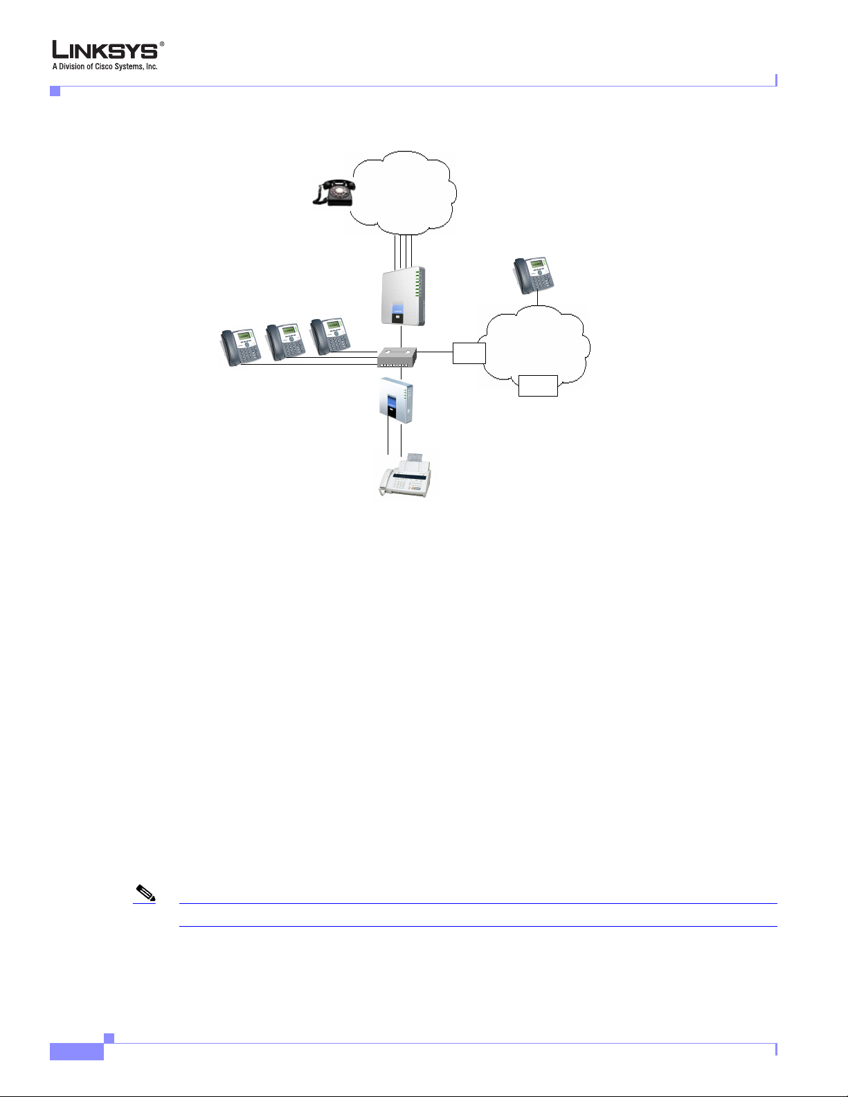
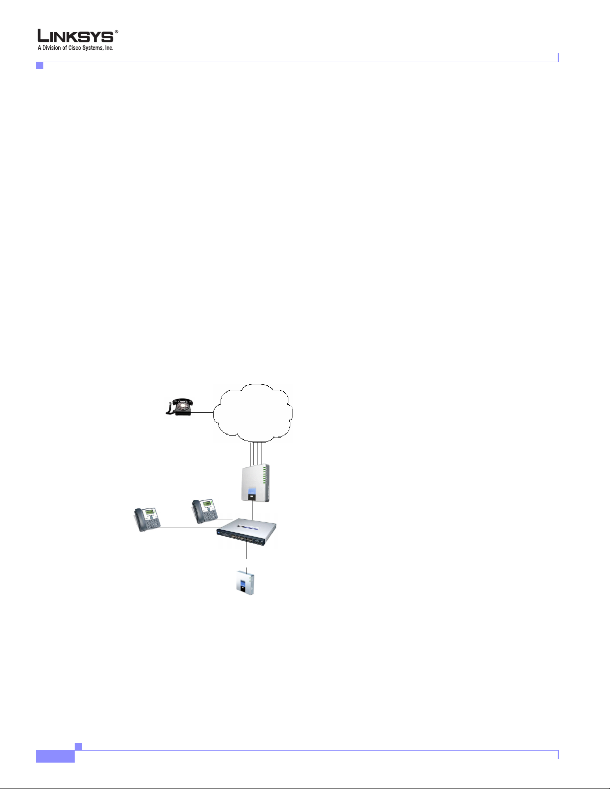
The LVS solution, illustrated in Figure 1-1, provides a line of IP communication products that include
the following:
• SPA9000 IP PBX
• SPA400 SIP-PSTN gateway
• SPA900 Series IP phones (SPA921, 922, 941, 942, and 962)
Linksys SPA9000 Administrator Guide
1-1
Page 16
The Linksys Voice System
Chapter 1 Using the Linksys Voice System
Figure 1-1 The Linksys Voice System (LVS) with the SPA9000 and SPA400
PSTN
Up to 4 FXO lines
Local voicemail
SPA400
SIP-PSTN
gateway
Switch
ISP
SPA901, 921, 922, 941, 942, 962
Internet
ITSP
SPA9000
IP PBX
FXS1
Fax/Analog
Phones
FXS2
The LVS 9000 system uses the power of VoIP to provide enterprise-quality telephony features to small
office/home office (SOHO) and small businesses. The LVS is based on open standards, such as SIP,. This
allows interoperation with other standards-based products and simplifies configuration and use. The
SPA9000, with a base license, supports up to four IP phones and up to 16 phones with an upgraded
license.
With the optional SPA400, the SPA9000 can also manage calls to and from the PSTN. The SPA9000 also
includes an Analog Telephone Adapter (ATA), with two FXS ports for connecting analog telephones, fax
devices, or an external music source for the music on-hold service included with the SPA9000.
The SPA9000 supports four independent line interfaces with numbers assigned by one to four different
ITSPs, with each line supporting up to 16 extensions. If the service provider supplies a group of
sequential direct inward dial (DID) phone numbers (such as 408-777-1000 through 777-1015) the
SPA9000 can support all the assigned numbers on a single line interface.
For information about LVS architecture, refer to the “SPA9000 Architecture” section on page 1-11.
SPA400 SIP-PSTN Gateway and Voicemail
The SPA400 is optionally used with the SPA9000 to provide a SIP-PSTN gateway, providing voice
connectivity between the PSTN and local client stations connected to the SPA9000. It also provides a
local voicemail server.
Note The SPA400 provides four FXO ports and occupies one line interface on the SPA9000.
A total of four SPA400 devices can be configured per SPA9000, using up to 16 analog phone lines and,
with the SPA9000, automatically routing calls to and from your existing PSTN telephone service.
Linksys SPA9000 Administrator Guide
1-2
Version 3.0
Page 17

Chapter 1 Using the Linksys Voice System
Designed to be implemented with the SPA9000, the SPA400 lets cost-conscious business users take
advantage of all the high-value features on the LVS, which are typically found on much more expensive
voice communications systems. The SPA400 includes an integrated voicemail application supporting up
to 32 voicemail accounts with customized greetings, providing LVS users the ability to receive and
playback voicemail messages. The SPA400 ships with a USB voicemail module, which stores voicemail
prompts and allows recording of up to four hours of high-quality voice messages.
For detailed information about using the SPA400 voice services and voicemail servers, refer to
Chapter 3, “Configuring Voice Service and Voicemail.”
Auto-Attendant
The Auto-Attendant is an internal service within the SPA9000. It plays pre-recorded voice messages that
offer the caller a menu of choices, so the Auto-Attendant can appropriately direct the call. After the
caller has made a choice, the call is routed to the appropriate extension. When the Auto-Attendant is
enabled, it parses and operates on user input (key presses or DTMF tones) following the rules specified
in the Auto-Attendant script on the SPA9000.
For detailed information about using and configuring the Auto-Attendant, refer to Chapter 5,
“Configuring the LVS Auto-Attendant.”
The Linksys Voice System
SPA9000 System Features
This following summarizes the features provided by the SPA9000:
• SIP Application Server, Proxy, Registrar and Location Server (RFC3261)
• Multiple Service Provider Lines / SIP Account Support (4)
• Shared Line Appearance (SLA)
• Configurable AA Answer Delay
• Interactive Voice Response (IVR)
• Recordable IVR Prompts
• Automatic Call Distribution (ACD)
• Configurable Call Routing
–
Least Cost Routing
–
Multiple DID Numbers Per VoIP Line
–
Call Routing to Multiple Extensions or Targeted User
–
Call Hunting - Sequential, Round Robin, Random
• Phone Configuration and Management Server
–
Discovery and Configuration of IP Phones
–
Assignment of Extension
–
Assignment of Dial plan
–
Proxy Logging of SIP Messages
Version 3.0
–
Phone Firmware Upgrade Management
• Corporate Directory with Automatic Update
Linksys SPA9000 Administrator Guide
1-3
Page 18

The Linksys Voice System
Chapter 1 Using the Linksys Voice System
• Configuration and Maintenance via Web Interface (Local or Remote
–
Status Display of All Connections
• Remote Configuration via
–
HTTPS with XML Formatted Files
–
HTTP or TFTP with 256-Bit Encrypted Binary Files
• Call Park -User Definable Parking Space Number
• Call Unpark
• Call Transfer - Attended and Blind
• Call Forward
• Group Paging
• Intercom
• Directed Call Pick Up
• Group Call Pick Up
• Music / Information via Streaming Audio Server (SAS) for Calls:
–
On Hold
–
Parked in the Parking Lot
–
Being Transferred
• Simultaneous Ringing (Find Me Service)
• Do Not Disturb
• Voice Mail Integration - Service Provider Based
–
Voice Mail Notification via SUBSCRIBE / NOTIFY
–
Forward Call Directly to Voice mail
• Integrated Media Proxy or Direct RTP Routing to ITSP
• Differentiated Services (DiffServ) / Type of Service (TOS) Support
• Two FXS (RJ-11) ports for Phones, Fax machines, Media Adapters
• Voice encoding with G.711 (64kbit/s) and other codecs (G.723, G.726, and G.729
• Fax Support using G.711 Pass-Through or T.38
• Echo Cancellation (G.165)
• Line Status - Active Line Indication, Name/Number
• Digits Dialed with Number Auto-Completion
• Call Hold
• Call Waiting
• Call Conferencing
1-4
• Automatic Redial
• Call Pick Up - Selective and Group
• Call Forwarding - Unconditional, No Answer, On Busy
Linksys SPA9000 Administrator Guide
Version 3.0
Page 19

Chapter 1 Using the Linksys Voice System
Additional Features When Used with SPA900 Series IP Phones
The following lists the additional features available when using the SPA9000 with SPA900 Series IP
phones:
• Line Status - Active Line Indication, Name/Number
• Digits Dialed with Number Auto-Completion
• Call Hold
• Call Waiting
• Call Transfer - Attended and Blind
• Call Conferencing
• Automatic Redial
• Call Pick Up - Selective and Group
• Call Swap
• Call Forwarding - Unconditional, No Answer, On Busy
• Hot Line and Warm Line Automatic Calling
• Call Log (60 entries each): Made, Answered, Missed Calls
The Linksys Voice System
• Personal Directory with Auto-dial (100 entries)
• Do Not Disturb
• URI (IP) Dialing Support (Vanity Numbers)
• On Hook Default Audio Configuration (Hands Free/Headset)
• Multiple Ring Tones with Selectable Default Ring Tone per Line
• Called Number with Directory Name Matching
• Calling Number with Name - Directory Matching or via Caller ID
• Subsequent Incoming Calls with Calling Name and Number
• Date and Time with Intelligent Daylight Savings Support
• Call Duration with Call Time Stamp Stored in Call Logs
• Name/Identity (Text) Display at Start Up
• Distinctive Ringing Based on Calling and Called Number
• User Downloadable Ring Tones and Ring Tone Generator (Free from www.linksys.com)
• Download on Demand Ring Tones - 10
• Speed Dial Support
• Configurable Dial/Numbering Plan Support - per Line
• DNS SRV and Multiple A Records for Proxy Lookup and Proxy Redundancy
• Syslog, Debug, Report Generation and Event Logging
Version 3.0
• Secure Call Encrypted Voice Communication Support
• Built-in Web Server for Admin and Config with Multiple Security Levels
• Automated Provisioning, Multiple Schemes-Up to 256 Bit Encryption: (HTTP, HTTPS, TFTP)
• Require Admin Password to Reset Unit to factory Defaults Option
Linksys SPA9000 Administrator Guide
1-5
Page 20
Technology Background
Technology Background
This section provides background information about the technology and protocols used by the SPA9000
system. It includes the following topics:
• Session Initiation Protocol, page 1-6
• SPA9000 Media Proxy, page 1-7
• Using the SPA9000 with a Firewall or Router, page 1-8
• SPA400 SIP-PSTN Gateway, page 1-8
• Network Address Translation (NAT), page 1-9
Session Initiation Protocol
The LVS is implemented using open standards, such as Session Initiation Protocol (SIP), allowing
interoperation with all ITSPs supporting SIP.
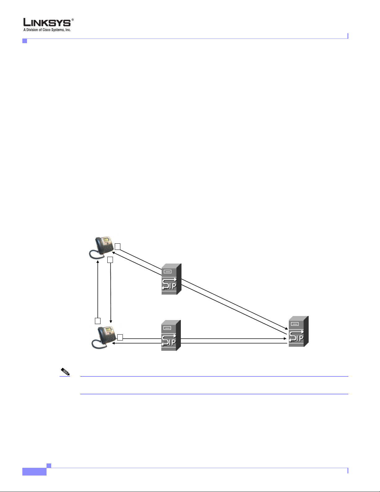
another subscriber in the network. In the SIP protocol, the requestor of the session is called the user agent
server (UAS), while the receiver of the request is called the user agent client (UAC).
Chapter 1 Using the Linksys Voice System
Figure 1-2 illustrates a SIP request for connection to
Figure 1-2 SIP Requests and Responses
SIP UA
2
4
SIP Proxy
RTP
SIP Proxy
3
SIP Proxy
1
SIP UA
Note In this manual, the term client station is used to describe any SIP UA (including IP phones) that registers
with the SPA9000.
1-6
In a SIP VoIP network, when the SIP proxy receives a request from a client station (UAS) for a
connection and it does not know the location of the UAC, it forwards the message to another SIP proxy
in the network. Once the UAC is located and the response is routed back to the UAS, a direct peer-to-peer
session is established between the two UAs. The actual voice traffic is transmitted between UAs over
dynamically assigned ports using the Real-time Protocol (RTP).
Linksys SPA9000 Administrator Guide
Version 3.0
Page 21
Chapter 1 Using the Linksys Voice System
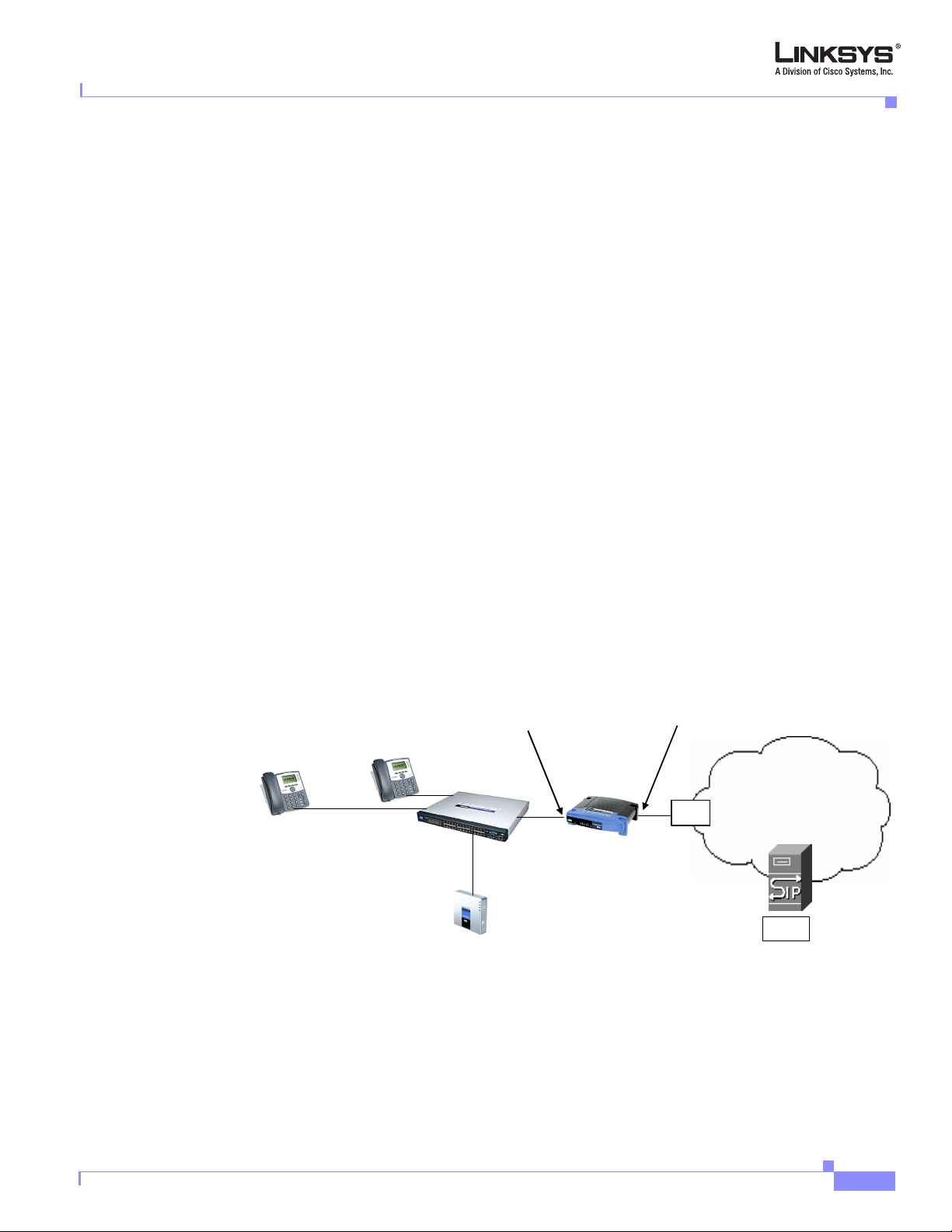
In Figure 1-3, UserA and UserB are client stations (UAs) that register over the local area network to
which the SPA9000 PBX is connected. When UserA calls UserB, the SPA9000 acts as a SIP proxy and
establishes a session between the two UAs. After the session is established, RTP traffic flows directly
between the two client stations.
Figure 1-3 SPA9000 as a SIP Proxy
Technology Background
UserC
UserA
UserB
Internet (WAN) Interface
Switch
IP Router (firewall)
Broadband modem
ISP
Internet
SPA9000
ITSP
SIP Proxy
When a user picks up the handset in an LVS system, the SPA9000 collects DTMF digits from a touchtone
analog telephone or the locally connected SPA900 Series IP phones. Unless the call is for a local client
station, the SPA9000 system sends the full number in a SIP INVITE message to another SIP proxy server
for further call processing.
To minimize dialing delay, a dial plan is maintained that is matched against the cumulative number
entered by the user. Invalid phone numbers that are not compatible with the dial plan are detected and
the user is alerted using a configurable tone (reorder) or announcement.
Figure 1-3 also illustrates connectivity between the SPA9000 and the ITSP over the Internet. When
UserA calls UserC, the SPA9000 directs the request to the SIP proxy at the ITSP, which is then
responsible for routing the request to UserC. Again, once the session is established, RTP packets are
exchanged directly between UserA and UserC. However, this requires that the firewall on the Internet
routers allow UserA access to the Internet. Because the SIP UAs are generally assigned IP addresses
dynamically through DHCP, this makes implementing a secure firewall policy more difficult.
SPA9000 Media Proxy
To address this possible security issue, the SPA9000 can also function as a media (RTP) proxy. This
option forces RTP traffic destined for the Internet (or IP WAN) to be directed to the SPA9000, which
then directs it to the remote UA. This configuration may simplify firewall configuration because the
client stations do not require direct access to the Internet through the firewall.
To enable the media proxy, set the PBX Parameters:<Force Media Proxy> parameter to Tru e . With the
media proxy enabled, when UserA calls User C, the SPA9000 still acts as the SIP proxy and forwards
the request to the SIP server on the ITSP. However, even after the SIP session is established, the
SPA9000 continues to direct RTP packets between UserA and the ITSP.
Version 3.0
Linksys SPA9000 Administrator Guide
1-7
Page 22
Technology Background
Local traffic is not affected by this configuration. When UserA initiates a call to UserB, RTP traffic still
flows directly between the two UAs. The media proxy only affects RTP traffic to a UA connected
through the ITSP.
Using the SPA9000 with a Firewall or Router
When using the SPA9000 behind a firewall or router, make sure that the following ports are not blocked:
• SIP ports—By default, UDP port 5060 and 5061
• RTP ports—16384 to 16482
Also disable SPI if this function exists on your firewall.
SPA400 SIP-PSTN Gateway
When a local user on the SPA9000 network initiates a call to a PSTN subscriber, the SPA400 acts as the
SIP-PSTN gateway, which converts the SIP and RTP media packets into the appropriate signal for
transmission to the PSTN switch. For example, if UserA calls UserD, the SIP request is routed by the
SIP proxy in the SPA9000 to the SPA400. The SPA400 then converts the SIP and RTP packets it receives
from UserA and the signals it receives from the PSTN switch.
Chapter 1 Using the Linksys Voice System
Figure 1-4 The SPA400 as a SIP-PSTN Gateway
PSTN
1 to 4 DID lines
SPA400
SIP-PSTN
Gateway
Switch
SIP Proxy
UserA
UserD
UserB
Internet (WAN) Interface
SPA9000
1-8
Linksys SPA9000 Administrator Guide
Version 3.0
Page 23
Chapter 1 Using the Linksys Voice System
Network Address Translation (NAT)
This section describes issues that arise when using the LVS on a network behind a network address
translation (NA) device. It includes the following topics:
• NAT Overview, page 1-9
• NAT Types, page 1-10
• Simple Traversal of UDP Through NAT, page 1-10
• SIP-NAT Interoperation, page 1-11
NAT Overview
Network Address Translation (NAT) allows multiple devices to share the same public, routable, IP
address for establishing connections over the Internet. NAT is typically performed by a router that
forwards packets between the Internet and the internal, private network.
A typical application of a NAT is to allow all the devices in a subscriber home network to access the
Internet through a router with a single public IP address assigned by an ISP. The IP header of the packets
sent from the private network to the public network is substituted by NAT with the public IP address and
a port assigned by the router. The receiver of the packets on the public network sees the packets as
coming from the external address instead of the private address of the device.
Technology Background
The association between a private address and port and a public address and port is called a NAT
mapping. This mapping is maintained for a short period of time, that varies from a few seconds to several
minutes. The expiration time is extended whenever the mapping is used to send a packet from the source
device.
Figure 1-5 NAT Support with Session Border Controller Provided by ITSP
192.168.1.101
Private IP address
192.168.1.1
192.168.1.102
NAT Device
External IP address
assigned by ISP
DHCP
server
ISP
Internet
SPA9000
ITSP
SIP Proxy
192.168.1.100
Session Border
Controller
Version 3.0
The ITSP may support NAT mapping using a Session Border Controller. This is the preferred option
because it eliminates the need for managing NAT on the SPA9000. If this is not available, you will need
to discuss with the ITSP how to use the NAT Support Parameters provided by the SPA9000, such as
<Outbound Proxy> and <STUN Server Enable>.
Linksys SPA9000 Administrator Guide
1-9
Page 24

Technology Background
NAT Types
Chapter 1 Using the Linksys Voice System
The different ways that NAT is implemented is sometimes divided into the following categories:
• Full cone NAT—Also known as one-to-one NAT. All requests from the same internal IP address and
port are mapped to the same external IP address and port. An external host can send a packet to the
internal host, by sending a packet to the mapped external address
• Restricted cone NAT—All requests from the same internal IP address and port are mapped to the
same external IP address and port. Unlike a full cone NAT, an external host can send a packet to the
internal host only if the internal host had previously sent a packet to it.
• Port restricted cone NAT/symmetric NAT—Port restricted cone NAT or symmetric NAT is like a
restricted cone NAT, but the restriction includes port numbers. Specifically, an external host can
send a packet to a particular port on the internal host only if the internal host had previously sent a
packet from that port to the external host.
With symmetric NAT all requests from the same internal IP address and port to a specific destination IP
address and port are mapped to a unique external source IP address and port. If the same internal host
sends a packet with the same source address and port to a different destination, a different mapping is
used. Only an external host that receives a packet can send a UDP packet back to the internal host.
Simple Traversal of UDP Through NAT
Simple Traversal of UDP through NATs (STUN) is a protocol defined by RFC 3489, that allows a client
behind a NAT device to find out its public address, the type of NAT it is behind, and the port associated
on the Internet connection with a particular local port. This information is used to set up UDP
communication between two hosts that are both behind NAT routers. Open source STUN software can
be obtained at the following website:
http://www.voip-info.org/wiki-Open+Source+VOIP+Software
STUN does not work with a symmetric NAT router. To determine the type of NAT your router uses,
complete the following steps:
Step 1 Enable debugging on the SPA9000:
1. Make sure you do not have firewall running on your PC that could block the syslog port (by default
this is 514).
2. On the administration web server, System tab, set <Debug Server> to the IP address and port number
of your syslog server.
Note that this address and port number has to be reachable from the SPA.
3. Set <Debug level> to 3 but you do not need to change the value of the <syslog server> parameter.
4. To capture SIP signaling messages, under the Line tab, set <SIP Debug Option> to Full. The output
is named syslog.514.log.
Step 2 To determine the type of NAT your router is using set <STUN Test Enable> to yes.
1-10
Step 3 View the syslog messages to determine if your network uses symmetric NAT or not.
Linksys SPA9000 Administrator Guide
Version 3.0
Page 25

Chapter 1 Using the Linksys Voice System
SIP-NAT Interoperation
In the case of SIP, the addresses where messages/data should be sent to a SPA9000 system are embedded
in the SIP messages sent by the device. If the SPA9000 system is sitting behind a NAT device, the private
IP address assigned to it is not usable for communications with the SIP entities outside the private
network.
Note If the ITSP offers an outbound NAT-Aware proxy, this discovers the public IP address from the remote
endpoint and eliminates the need to modify the SIP message from the UAC.
The SPA9000 system must substitute the private IP address information with the proper external IP
address/port in the mapping chosen by the underlying NAT to communicate with a particular public peer
address/port. For this, the SPA9000 system needs to perform the following tasks:
• Discover the NAT mappings used to communicate with the peer.
This can be done with the help of an external device, such as a STUN server. A STUN server
responds to a special NAT-Mapping-Discovery request by sending back a message to the source IP
address/port of the request, where the message contains the source IP address/port of the original
request. The SPA9000 system can send this request when it first attempts to communicate with a SIP
entity over the Internet. It then stores the mapping discovery results returned by the server.
SPA9000 Architecture
• Communicate the NAT mapping information to the external SIP entities.
If the entity is a SIP Registrar, the information should be carried in the Contact header that
overwrites the private address/port information. If the entity is another SIP UA when establishing a
call, the information should be carried in the Contact header as well as in the SDP embedded in SIP
message bodies. The VIA header in outbound SIP requests might also need to be substituted with
the public address if the UAS relies on it to route back responses.
• Extend the discovered NAT mappings by sending keep-alive packets.
Because the mapping is alive only for a short period, the SPA9000 system continues to send periodic
keep-alive packets through the mapping to extend its validity as necessary.
SPA9000 Architecture
This section describes the basic architecture, function, and configuration options for the SPA9000. It
includes the following topics:
• Architectural Components, page 1-12
• Multicast Addressing and Group Paging, page 1-13
• Configuration Options, page 1-14
Version 3.0
Linksys SPA9000 Administrator Guide
1-11
Page 26
SPA9000 Architecture
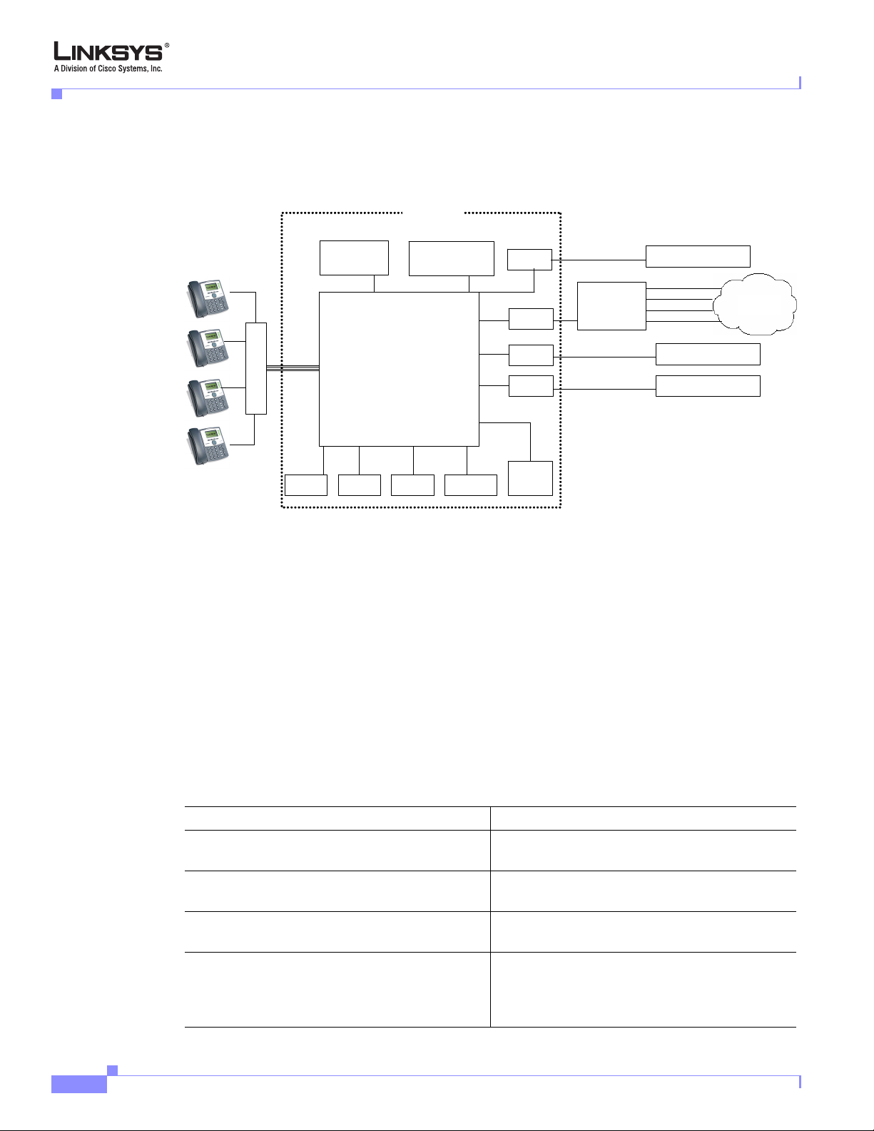
Architectural Components
Figure 1-6 SPA9000 Architecture
Chapter 1 Using the Linksys Voice System
SPA9000
Application
server
Switch
FXS1
SIP Registrar
Media (RTP) Proxy
FXS2
SIP Proxy
aa
Administration
web server
imusic
Line 1
Line 2
Line 3
Line 4
Call
park
(408)111-1000 to 7
SPA 400
SIP-PSTN
gateway
(949)111-2000 to 7
(888)111-3000 to 7
ITSP SIP Proxy
(408)111-1111
(408)111-1112
(408)111-1113
(408)111-1114
ITSP SIP Proxy
ITSP SIP Proxy
PSTN
As shown in Figure 1-6, the SPA 9000 provides four logical line interfaces, referred to as Line 1, 2, 3,
and 4. Each line can be configured with the same or a different ITSP. Each SPA400 also occupies one
line interface. The SPA9000 has five internal clients that register implicitly with the internal SIP proxy:
• FXS1 (fxs1)
• FXS2 (fxs2)
• Call Park (callpark)
• Auto-Attendant (aa)
• Internal Music Server (imusic)
1-12
FXS1 and FXS2 correspond to the two physical FXS ports. The FXS ports can only register with the
local SIP proxy. The Call Park is used to maintain calls that are parked, and AA is a scriptable
auto-attendant application.
Table 1-1 Architectural Components
Architectural Component Function
SIP proxy and Registrar server Accepts registration from client stations and
proxies SIP messages.
Media proxy server Proxies RTP packets between client stations and
proxies SIP messages.
Configuration server Serves configuration files to client stations and
auto configures un-provisioned client stations.
Application server Supports advanced features such as call
park/pickup, directory, directed call pickup and
group paging, hunt groups, and shared line
appearances.
Linksys SPA9000 Administrator Guide
Version 3.0
Page 27

Chapter 1 Using the Linksys Voice System
Table 1-1 Architectural Components
Architectural Component Function
Internal music source Streams audio files to client stations (both on-net
Administration web server Allows configuration and monitoring of the
ATA with 2 FXS ports Each FXS port can be connected to analog
Call park The call park is used to maintain calls that are
Auto-Attendant AA is a scriptable auto-attendant application that
SPA9000 Architecture
and off-net).
The FXS1 and FXS2 can optionally be connected
to an external music source
audio server (SAS). When working in this mode,
each FXS port can handle up to 10
calls.
SPA9000.
phones, fax machine, or an external music
source. Each port can support up to two calls
simultaneously. The FXS ports can only register
to the internal proxy server.
parked and can handle up to 10 calls
simultaneously
can handle up to 10 calls simultaneously
to act as a streaming
concurrent
Multicast Addressing and Group Paging
The <Multicast Address> parameter on the PBX Parameters page defines the multicast address used by
the SPA9000 and the SPA900 Series phones to communicate with each other. The default value is
224.168.168.168:6061. This address can also be set using the IVR option 181 and reviewed using option
180.
The <Group Page Address> parameter is used by the SPA9000 for group paging of all active client
stations. The default value is 224.168.168.168:34567.
The SPA9000 can send the following messages to the phone group:
• Graceful Reboot
• Immediate Reboot
• Graceful Restart
• Immediate Restart
• Group Page Start
• Group Page End
• Get Ringing Calls
Client stations send multicast messages to the SPA9000 when they are looking for the configuration
server.
Version 3.0
Linksys SPA9000 Administrator Guide
1-13
Page 28

SPA9000 Architecture
Configuration Options
This section describes the different methods for configuring the SPA9000. It includes the following
topics:
• Interactive Voice Response, page 1-14
• Setup Wizard
• Administration Web Server
• Local Client Configuration and Registration, page 1-15
• Remote Provisioning of the SPA9000, page 1-15
Interactive Voice Response
The Interactive Voice Response (IVR), which is strictly for administration purposes, lets you use an
analog phone to perform basic configuration and troubleshooting operations. To access the IVR, connect
an analog phone to an FXS port and press **** to access the IVR menu.
For detailed information about using the IVR, refer to the “Using the Interactive Voice Response
Interface” section on page 2-9. A convenient quick-reference for the IVR is available at the following
website:
Chapter 1 Using the Linksys Voice System
http://www.linksys.com/
Setup Wizard
The Setup Wizard is a convenient way to perform initial configuration for the SPA9000. It provides
step-by-step guidance for configuring the basic operation of voice services, voicemail, and most of the
main features provided by the SPA9000.
The Setup Wizard overwrites any existing configuration information that has been entered through the
administration web server, so it should not be used for ongoing administration and configuration unless
it provides adequate functionality for you to use it exclusively. You can, however, use the Setup Wizard
for initial configuration and then use the administration web server for ongoing configuration and
maintenance.
You can download the latest Setup Wizard from the following website:
http://www.linksys.com/
To start the Wizard, just double-click on the executable file. For information about getting started with
the Setup Wizard, refer to the
Administration Web Server
The administration web server provides a series of web pages that let you enter detailed configuration
information for the many features and options provided by the SPA9000. It also lets you monitor the
status of the attached client stations.
The administration server provides a basic and an advanced view from which the various configuration
parameters can be accessed. The Provisioning tab is only visible from the advanced Administrator
account view of the web interface.
“Using the Wizard for Initial Configuration” section on page 2-14
1-14
To access the administration web server, direct a browser to the Internet (WAN) interface of the
SPA9000. To determine this address, use IVR Option 110 #.
Linksys SPA9000 Administrator Guide
Version 3.0
Page 29

Chapter 1 Using the Linksys Voice System
For detailed information about using the administration web server, refer to the “Using the
Administration Web Server” section on page 2-23. For a description of each parameter provided by the
administration web server, refer to Chapter 6, “SPA9000 Field Reference”
Local Client Configuration and Registration
SPA9000 provides a TFTP server to assign configuration information to the locally attached client
stations. When the SPA9000 receives a request for /cfg/init_$MA.xml, it automatically assigns the next
available user id (extension number) to the client station. The initial user ID is configured using the PBX
Phone Parameters:<Next Auto User ID> parameter and is automatically incremented each time a new
number is assigned. Before assigning a new user ID, the SPA9000 also checks if there is any registered
client station using that ID and increases the ID until an unused value is found.
Remote Provisioning of the SPA9000
The SPA9000 provides for secure provisioning and remote upgrade. Provisioning is achieved through
configuration profiles transferred to the device via TFTP, HTTP, or HTTPS. User intervention is not
required to initiate or complete a profile update or firmware upgrade.
The SPA9000 can be configured to automatically resync its internal configuration state to a remote
profile periodically and during power up. The automatic resync is controlled by configuring the profile
URL for the device.
The SPA9000 accepts profiles in XML format, or alternatively in a proprietary binary format, which can
be generated by a profile compiler tool available to qualified VoIP vendors and partners from Linksys.
The SPA9000 supports up to 256-bit symmetric key encryption of profiles. For the initial transfer of the
profile encryption key (initial provisioning stage), the SPA9000 can receive a profile from an encrypted
channel (HTTPS with client authentication), or it can resync to a binary profile generated by the
Linksys-supplied profile compiler. In the latter case, the profile compiler can encrypt the profile
specifically for the target SPA9000, without requiring an explicit key exchange.
SPA9000 Architecture
Remote firmware upgrade is achieved via TFTP or HTTP (firmware upgrades using HTTPS are not
supported). Remote upgrades are controlled by configuring the desired firmware image URL into the
SPA9000 via a remote profile resync.
For further information about remote provisioning refer to the LVS SPA Provisioning Guide.
Version 3.0
Linksys SPA9000 Administrator Guide
1-15
Page 30

Where to Go From Here
Where to Go From Here
The following table summarizes the steps required to implement and configure the SPA9000 system and
indicates where to look for the information required.
Tas k Refer to
Establishing connectivity among system
components
Configuring voice services and SPA400 or
ITSP-hosted voicemail
Configuring and understanding SPA9000 features Chapter 4, “Configuring SPA9000 Features.”
Configuring or writing XML scripts for the
Auto-Attendant
Identify the function or setting required for a
specific parameter on the administration web
server pages
For additional information about specific functionality or features of the SPA9000, refer to the following
documents:
Chapter 1 Using the Linksys Voice System
Chapter 2, “Getting Started.”
Chapter 3, “Configuring Voice Service and
Voicemail.”
Chapter 5, “Configuring the LVS
Auto-Attendant.”
Chapter 6, “SPA9000 Field Reference”
• LVS CTI Integration Guide
• LVS Integration with ITSP Hosted Voicemail Guide
• Auto-Attendant Quick Guide
• Interactive Voice Response (IVR) Quick Guide
• SPA Provisioning Guide
• SPA900 Series IP Phones Administrator Guide
1-16
Linksys SPA9000 Administrator Guide
Version 3.0
Page 31

CHA P T E R
2
Getting Started
This chapter provides the information required to implement a SPA9000 system, including
making the required network connections and establishing basic connectivity among the
system components. It includes the following sections:
• Implementing LVS, page 2-1
• Using the Interactive Voice Response Interface, page 2-9
• Initial Setup and Configuration, page 2-13
• Setting the SPA9000 Administrator Account Password, page 2-22
• Using the Administration Web Server, page 2-23
• Advanced Methods of Configuration, page 2-26
• Client Registration, page 2-32
• Troubleshooting and Configuration FAQ, page 2-33
Implementing LVS
This section describes the first steps in implementing a SPA9000 system (LVS). It includes the
following topics:
• Using the SPA9000 and SPA400 as a VoIP PBX System, page 2-2
• Using the LVS as a Key System, page 2-3
• SPA9000 Hardware, page 2-4
• SPA400 Hardware, page 2-6
• Bandwidth Requirements, page 2-6
• Caring for Your Hardware, page 2-7
• Making the Physical Connections, page 2-8
Version 3.0
Linksys SPA9000 Administrator Guide
2-1
Page 32

Implementing LVS
Using the SPA9000 and SPA400 as a VoIP PBX System
Figure 2-1 illustrates the hardware required to implement a SPA9000 system with the SPA400
connected to the PSTN.
Figure 2-1 SPA9000 and SPA400 System Hardware
PSTN
Chapter 2 Getting Started
PC connected
through SPA9x2 IP phone
SPA901, 921, 922, 941, 942, 962
Internet (WAN) Interface
SPA9000
Up to 4 FXO lines
SPA400
(optional)
Hub/switch
IP Router/
Broadband
Modem
ISP
Public
Internet
ITSP
The following are the basic hardware requirements to implement an LVS PBX system:
• SPA9000
• One or more SPA900 series IP Phones (as client stations)
• Ethernet network cables
• One or more Ethernet switches with QoS support and with the required number of available ports
• A PC for configuration of the SPA9000 and other client stations on the network. This can be
connected to the switch or directly to the Ethernet port on the SPA922, 942, or 962 IP phone.
The following components can optionally be added to provide additional functionality:
2-2
• FAX machine to send or receive faxes
• A router with QoS support, and a broadband (cable/DSL) modem (gateway) with connectivity to an
ISP
• SPA400 SIP-PSTN gateway for connectivity to the PSTN and local voicemail service
• PSTN DID lines
For best results, use a router and switch that both support Quality of Service (QoS). QoS allows
top priority to be assigned to voice traffic. Otherwise, the quality of the voice connection may
suffer when large files are moved over the network.
Note The SPA9000, the SPA400, and the SPA900 Series IP phones should all be within the same LAN.
Separating the devices through VPN encryption, firewalls, routers, or other devices that affect multicast
traffic may prevent proper functioning of the IP PBX system.
Linksys SPA9000 Administrator Guide
Version 3.0
Page 33

Chapter 2 Getting Started
\In addition, you need at least one active ITSP phone service account and its settings (including
DID number for incoming calls) if you use the Internet for telephone service. If you are using
the SPA400 for connection to the PSTN, you need at least one active PSTN line.
The LVS can also be implemented with hosted voicemail services provided by the ITSP. In this
scenario, the SPA-400 is not configured for voicemail, but is only used for as a SIP-PSTN
gateway, providing telephone connectivity to PSTN subscribers.
Note For first-time installation of the SPA9000, it is recommended that you use the SPA9000 Setup Wizard,
which you can download from www.linksys.com. For further information, see
Initial Configuration” section on page 2-14.
Using the SPA9000 as a Media Proxy
The SPA9000 can as a media proxy, which means that all RTP traffic between local client
stations and client stations on the Internet are routed through the SPA9000. This simplifies
firewall configuration because only the SPA9000 requires access to the Internet through the
firewall.
Implementing LVS
“Using the Wizard for
By default, the SPA9000 acts only as a SIP proxy. This means that once a SIP connection is
established, further communication between the SIP UAs occurs directly. To enable the
SPA9000 as a media proxy, set the PBX Parameters:<Force Media Proxy> parameter to yes.
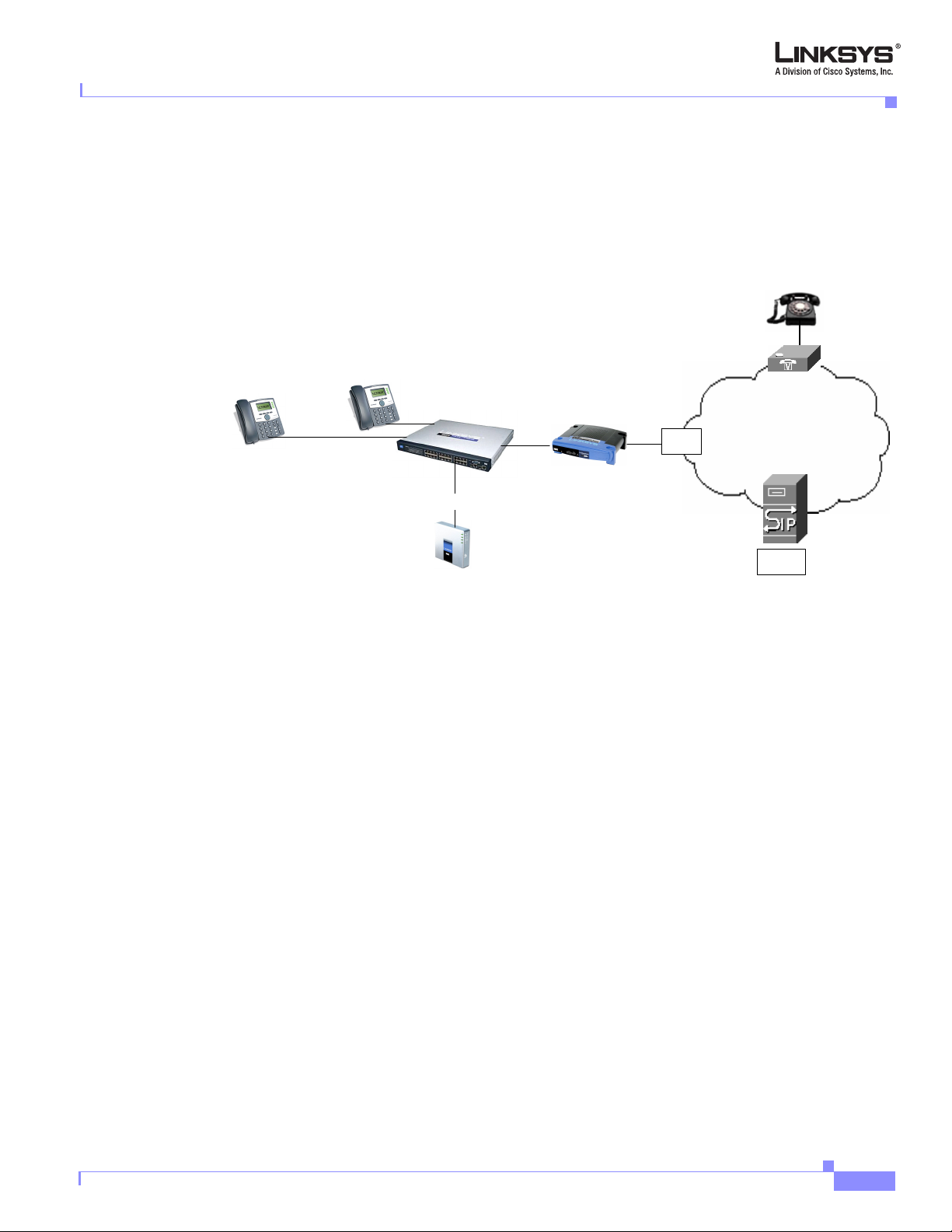
Using the LVS as a Key System
An easy and cost-effective way to implement the SPA9000 is as a replacement of a legacy key
system, in which a single DID line from the PSTN supports a single extension. In a key system
all lines appear as shared lines. This allows a user to pick up a ringing line from any phone in
the key system (see
Figure 2-2).
Version 3.0
Linksys SPA9000 Administrator Guide
2-3
Page 34

Implementing LVS
Chapter 2 Getting Started
Figure 2-2 Using LVS with SPA9000 and SPA400 as a Key System
PSTN
Up to 4 DID lines per SPA400
Shared line appearance
When implementing the SPA9000 and SPA400 as a key system, the SPA9000 is connected
through a switch to one or more SPA400s, which are then connected to the existing DID lines
from the PSTN. The SPA9000 has four line interfaces, each of which can support one SPA400
or a single VoIP account with an ITSP. A single VoIP account with an ITSP can map to multiple
DID numbers assigned by the ITSP.
Each SPA400 can support up to four DID lines assigned by the PSTN, so with a SPA400
connected to all four line interfaces, the SPA9000 can support up to 16 DID lines to the PSTN.
SPA9000 Hardware
Hub/switch
Internet (WAN) Interface
SPA9000
1 to 4 SPA400s
IP Router/
Broadband modem
ISP
Internet
ITSP
2-4
The following are the ports provided by the SPA9000:
• Two analog (FXS) telephone ports (Phone 1 and Phone 2), which are designed for use by the
following devices:
–
Analog telephone
–
Fax machine
–
Music/audio player with a music source adapter (RJ11-to-Line-In) for use as a Streaming Audio
Server (SAS)
• Two Ethernet ports, designed for the following functions:
–
Ethernet: administrative access for troubleshooting with a directly connected PC or laptop
–
Internet: SIP call traffic and signaling to client stations and administration web server access
(through switch)
Linksys SPA9000 Administrator Guide
Version 3.0
Page 35

Chapter 2 Getting Started
SPA9000 Back Panel
The SPA9000 ports are located on the back panel.
Figure 2-3 SPA9000 Back Panel
The following are the interfaces provided by the SPA900, from left to right:
• Phone 1/2—Connect to an analog telephone or fax machine with an RJ-11 cable.
• Internet—Connect to a switch, router, or broadband (cable/DSL) modem. Also referred to as the
• Ethernet—For troubleshooting only.
• Power—Connect to the power adapter.
Implementing LVS
WAN port, because it provides connectivity to the wide area VoIP network.
The Front Panel
The SPA9000 LEDs are located on its front panel.
Figure 2-4 SPA9000 Front Panel
The following are the LEDs provided by the SPA900, from left to right:
• Power—Steady green: powered on and connected to the Internet. Flashing: not connected to the
Internet or is booting or upgrading firmware.
• Ethernet—Steady green: active connection. Flashing: indicates traffic.
• Phone 1/2—Steady green: active/registered connection to ITSP through port. Flashing: in use or off
hook.
Version 3.0
Linksys SPA9000 Administrator Guide
2-5
Page 36

Implementing LVS
SPA400 Hardware
Figure 2-5 SPA400 Back Panel
The SPA400 provides the following interfaces (from left to right):
• USB—Use this to connect the SPA400 USB voicemail module containing voicemail prompts and
provides the storage location for saving voice mailbox messages.
• Ethernet—Connect to the SPA9000 through the appropriate switch.
• Line 1 to 4—Connect to the telephone line provisioned by your PSTN provider.
• Power—Connect to the power supply.
Chapter 2 Getting Started
Figure 2-6 SPA400 Front Panel
The SPA400 provides the following LEDs, from left to right:
• Power—Steady green: powered on and connected to the Internet. Flashing: not connected to the
Internet, booting, or upgrading firmware.
• Status—Steady green: SPA400 registered to the SPA9000. Flashing: SPA400 not registered.
• Line 1-4—Steady green: line is active; flashing: ringing; off: idle.
• Ethernet—Steady green: active connection. Flashing: indicates traffic.
• USB—Steady green: USB voicemail module registered. Off: no module detected.
Bandwidth Requirements
Depending on how you have your IP phones configured, each call requires 55 to 110 kbps in
each direction. Therefore, using G.729 as the voice codec setting, and with an average
business-grade broadband Internet connection supporting 1.5 Mbps downstream and 384 kbps
upstream, a total of seven (7) simultaneous conversations can be reliably supported with
adequate bandwidth available for file downloads.
2-6
Linksys SPA9000 Administrator Guide
Version 3.0
Page 37

Chapter 2 Getting Started
Implementing LVS
Linksys recommends using the SPA9000 with QoS-capable networking equipment that can
prioritize the VoIP application traffic. QoS features are available on many Linksys data
networking switches and routers. A QoS-enabled router prioritizes the packets going upstream
to the ISP.
Table 2-1 Ethernet Bandwidth Budget for Off-Net VoIP Calling
Codec
G. 71 1 110 kbps 220 kbps 440 kbps 660 kbps 880 kbps
G.726-40 87 kbps 174 kbps 348 kbps 522 kbps 696 kbps
G.726-32 79 kbps 158 kbps 316 kbps 474 kbps 632 kbps
G.726-24 71 kbps 142 kbps 284 kbps 426 kbps 568 kbps
G.726-16 63 kbps 126 kbps 252 kbps 378 kbps 504 kbps
G.729 55 kbps 110 kbps 220 kbps 330 kbps 440 kbps
This table is based on the following assumptions:
Table 2-1 illustrates the bandwidth budget using different codecs.
Approximate bandwidth budget for
each side of conversation
2 calls 4 calls 6 calls 8 calls
• Bandwidth Calculated with No Silence Suppression
• 20 Millisecond of payload per RTP packet
Note The use of silence suppression can reduce the average bandwidth budget by 30% or more.
For more information about bandwidth calculation, refer to the following websites:
http://www.erlang.com/calculator/lipb/
http://www.packetizer.com/voip/diagnostics/bandcalc.html
Caring for Your Hardware
The SPA 9000, SPA400, and the SPA900 Series phones are electronic device that should not
be exposed to excessive heat, sun, cold or water. To clean the equipment, use a slightly
moistened paper or cloth towel. Do not spray or pour cleaning solution directly onto the
hardware unit.
Version 3.0
Linksys SPA9000 Administrator Guide
2-7
Page 38

Implementing LVS
Making the Physical Connections
To establish or verify the necessary connectivity complete the following steps.
Note This includes the steps required to establish basic connectivity for LVS and does not address the
configuration of other networking components that may affect VoIP services.
To complete these steps, you need a multiport switch, Ethernet cables, the SPA9000, and a PC
connected to the network.
1. Connect a network cable between the SPA9000 Internet Port and the switch.
2. Connect a network cable between the computer you use to configure the SPA9000 and the switch.
3. Plug an analog phone into the Phone 1 port on the SPA9000.
4. Connect the included Power Adapter to the power port of the SPA9000.
The status LED starts flashing as the SPA9000 boots up.
5. Connect a network cable from the broadband modem to the Internet port of the broadband router.
6. Connect an network cable from one of the LAN ports of the router to the Uplink port of the LAN
switch.
Chapter 2 Getting Started
7. Connect the power adapters to the power ports of the broadband router and the LAN switch.
8. If the SPA9000 has been used previously, reset it to its factory defaults before starting configuration.
a. Connect an analog phone to Phone 1 or Phone 2.
b. Press **** to access the IVR menu.
For detailed information about the IVR system, refer to “Using the Interactive Voice Response
Interface” section on page 2-9.
c. Press 73738# and then 1#.
This resets the unit to its factory defaults.
d. Wait about 30 seconds while the system reboots.
2-8
Linksys SPA9000 Administrator Guide
Version 3.0
Page 39

Chapter 2 Getting Started
Using the Interactive Voice Response Interface
Using the Interactive Voice Response Interface
This section describes how to read or write basic network configuration settings using a
touchtone telephone connected to one of the FXS (RJ-11) phone ports of the SPA9000. It
includes the following topics:
• Using the IVR Menu, page 2-9
• IVR Options, page 2-10
• Entering a Password through the IVR, page 2-12
By default, there is no password required for any of the IVR options. If the Administrator
account password is set, password authentication is required for some options.
The interactive voice response (IVR) features that are available depend on your system
configuration. A convenient quick-reference for the IVR is available at the following website:
http://www.linksys.com/
Using the IVR Menu
To use the IVR menu, complete the following steps.
Step 1 Connect an analog telephone to the Phone 1 or Phone 2 port of the SPA9000.
Note You can only access the IVR menu through an analog telephone, not an IP phone.
Step 2 Press **** (quickly press the star key four times).
Wait until you hear “Linksys configuration menu.”
Note You cannot access the IVR from a phone that is currently connected to a call.
Step 3 Refer to Table 2-2 to identify the option required.
Step 4 Enter the required option followed by the # (pound) key.
To enter a period, use the star key (*).
When entering a value, such as an IP address, to exit without entering any changes, press the
* (star) key twice within half a second. Otherwise, the * is treated as a decimal point.
After entering a value, such as an IP address, press the # (pound) key to indicate you have
finished your selection. To save the new setting, press 1. To review the new setting, press 2. To
re-enter the new setting, press 3. To cancel your entry and return to the main menu, press *
(star).
Version 3.0
For example, to enter the IP address 191.168.1.105 by keypad, press these keys:
191*168*1*105. Press the # (pound) key to indicate that you have finished entering the IP
address. Then press 1 to save the IP address or press the * (star) key to cancel your entry and
return to the main menu.
Linksys SPA9000 Administrator Guide
2-9
Page 40

Chapter 2 Getting Started
Using the Interactive Voice Response Interface
If the menu is inactive for more than one minute, the SPA9000 times out. You need to re-enter
the menu by pressing ****.
Step 5 To exit the menu, hang up the telephone.
The settings you have saved take effect after you hang up the telephone. The SPA9000 may reboot
at this time.
IVR Options
Table 2-2 summarizes the options provided by the IVR.
Table 2-2 IVR Options
IVR Action IVR Menu Choice Parameter(s) Notes
Enter IVR Menu * * * * None Ignore SIT or other tones until you
hear, “Linksys configuration menu.
Please enter option followed by the
pound key or hang-up to exit.”
Exit IVR Menu 3948 None
Check DHCP 100 None IVR announces if DHCP in enabled or
disabled.
Enable/Disable DHCP 101 Enter 1 to enable
Requires password
Enter 0 to disable
Check WAN IP
Address
Set Static IP Address 111 Enter IP address using
110 None IVR announces the current IP address
of the WAN port.
DHCP must be “Disabled,” otherwise
numbers on the telephone
key pad. Use the * (star)
key when entering a
you hear, “Invalid Option,” if you try
to set this value.
Requires password
decimal point.
Check Network Mask 120 None IVR announces the current network
mask of SPA.
Set Network Mask 121 Enter value using numbers
on the telephone key pad.
Use the * (star) key when
entering a decimal point.
Check Static Gateway
130 None IVR announces the current gateway
IP Address
DHCP must be “Disabled,” otherwise
you hear, “Invalid Option,” if you try
to set this value.
Requires password
IP address of SPA.
2-10
Linksys SPA9000 Administrator Guide
Version 3.0
Page 41

Chapter 2 Getting Started
Table 2-2 IVR Options (continued)
Using the Interactive Voice Response Interface
Set Static Gateway IP
Address
131 Enter IP address using
numbers on the telephone
key pad. Use the * (star)
key when entering a
DHCP must be “Disable,” otherwise
you hear, “Invalid Option,” if you try
to set this value.
Requires password
decimal point.
Check MAC Address 140 None IVR announces the MAC address of
SPA in hex string format.
Check Firmware
Ve rs i on
Check Primary DNS
Server Setting
Set Primary DNS
Server
150 None IVR announces the version of the
firmware running on the SPA.
160 None IVR announces the current setting in
the <Primary DNS> parameter.
161 Enter IP address using
Requires password
numbers on the telephone
key pad. Use the * (star)
key when entering a
decimal point.
Check administration
web server port
170 None IVR announces the port that the web
server is listening on. (Default is 80)
Check LAN IP Address 210 None IVR announces the current IP address
of the LAN port.
Check PBX multicast
180 None IVR announces the current value.
address
Set PBX multicast
address
181 Enter IP address and port.
Use * key for entering a
Enter a * between the IP address and
the Port fields. Requires Password
dot. For example,
224.168.168.169:8089 is
224*168*168*169*8089.
Enable/Disable
administration web
7932 Enter 1 to enable
Enter 0 to disable
Requires password
server
Manual Reboot of Unit 732668 None After you hear “Option Successful,”
hang up. Unit reboots automatically.
Version 3.0
Linksys SPA9000 Administrator Guide
2-11
Page 42

Using the Interactive Voice Response Interface
Table 2-2 IVR Options (continued)
Chapter 2 Getting Started
User Factory Reset of
Unit
WARNING:
ALL
“User-Changeable”
NON-DEFAULT
SETTINGS WILL BE
LOST!
This might include
network and service
provider data.
Factory Reset of Unit
WARNING:
ALL NON-DEFAULT
SETTINGS WILL BE
LOST!
This includes network
and service provider
data.
877778 Enter 1 to confirm
Enter *(star) to cancel
operation
73738 Enter 1 to confirm
Enter * (star) to cancel
operation
SPA prompts for confirmation. After
confirming, you hear “Option
Successful.” Hang up. Unit reboots
and all “User Changeable”
configuration parameters are reset to
factory default values.
SPA prompts for confirmation. After
confirming, you hear “Option
Successful.” Hang up. Unit reboots
and all configuration parameters are
reset to factory default values.
Note The items marked with “Requires Password” only require a password if the Administrator password is
set.
Entering a Password through the IVR
To input the password using the phone keypad, the following translation convention applies:
–
To input: A, B, C, a, b, c—press “2’
–
To input: D, E, F, d, e, f—press “3’
–
To input: G, H, I, g, h, i—press “4’
–
To input: J, K, L, j, k, l— press “5’
–
To input: M, N, O, m, n, o—press “6’
–
To input: P, Q, R, S, p, q, r, s—press “7’
–
To input: T, U, V, t, u, v—press “8’
–
To input: W, X, Y, Z, w, x, y, z—press “9’
–
To input all other characters in the Administrator account password, press “0’
Note This translation convention only applies to the password input.
2-12
Linksys SPA9000 Administrator Guide
Version 3.0
Page 43

Chapter 2 Getting Started
Initial Setup and Configuration
For example, to input password test#@1234 by phone keypad, you need to press the following
sequence of digits: 8378001234.
1. After entering a value, press the # (pound) key to indicate end of input.
–
To save value, press 1.
–
To review the value, press 2.
–
To re-enter the value, press 3.
–
To cancel the value entry and return to the main configuration menu, press *’ (star).
Notes:
–
The final # key is not included in the password value.
–
Saved settings take effect when the telephone is hung-up, and if necessary, the SPA9000
automatically reboots.
2. After one minute of inactivity, the unit times out. The user needs to re-enter the configuration menu
from the beginning by pressing * * * *.
Initial Setup and Configuration
This section describes how to complete the initial connection and configuration of the
SPA9000 system. It includes the following topics:
• Licensing, page 2-13
• Using DHCP or Static IP Addressing, page 2-13
• Using the Wizard for Initial Configuration, page 2-14
• Using the Wizard to Upgrade Software, page 2-19
Licensing
The SPA9000 is shipped from the factory with a four-user license. This means that the
SPA9000 allows registration from up to four external IP addresses (first come/first serve). If
you need to support more client stations, you can purchase a 16-user license and install it by
entering the license key using the <License Keys> parameter on the Provisioning page. To
obtain a license, contact sipura-sales@cisco.com.
Using DHCP or Static IP Addressing
Before running the Setup Wizard, you need to decide if you are using DHCP or static IP
addressing. Static IP addressing is recommended for the SPA400. The SPA900 series phones
typically obtain their addresses through the DHCP server on the broadband router that connects
to the broadband modem. The SPA9000 can either be assigned a static address if this has been
provided by your ISP, or it can be assigned a dynamic IP address by the DHCP server on your
router or by the ISP.
Version 3.0
Linksys SPA9000 Administrator Guide
2-13
Page 44

Initial Setup and Configuration
If you are using static IP addressing for the SPA400, you need to know the correct static IP
address to assign. To determine the dynamically assigned address of the SPA400, you can use
the Setup Wizard or view the DHCP client table for the broadband router.
To determine the current IP address of the SPA9000, complete the following steps.
Step 1 Connect an analog telephone to one of the FXS (RJ-11) ports on the SPA9000.
Step 2 Press **** on the keypad to access the IVR menu.
Step 3 Press 110# and note the response.
Using the Wizard for Initial Configuration
Step 1 After completing the required physical network connections and powering on all devices, start the SPA
Setup Wizard.
The latest wizard can be obtained at the following URL:
Chapter 2 Getting Started
www.linksys.com/
Figure 2-7 shows the first screen that you should see.
Figure 2-7 SPA Setup Wizard—Page 1
Step 2 Click Next.
2-14
The subsequent screen provides a review of the setup requirements that are required to
successfully complete the wizard. After verifying that you have completed the required setup,
click Next.
The system displays Page 3 of the wizard (see Figure 2-8).
Linksys SPA9000 Administrator Guide
Version 3.0
Page 45

Chapter 2 Getting Started
Step 3 If you are configuring the SPA9000 for the first time, accept the default and click Next on Page 3.
Initial Setup and Configuration
Figure 2-8 SPA Setup Wizard—Page 3
If you are using the wizard to change your existing configuration, click the second radio button
on Page 3 and enter the IP address of your SPA9000 on the page that appears.
Note If you use the Setup Wizard to configure the SPA9000 after using the administration server web, you
may lose any changes to the factory default configuration that you made using the administration server
web pages.
Complete the following steps before continuing with the wizard:
1. Connect a multi-port switch to the router in your network.
2. Connect the Internet port on the SPA9000 to the switch.
3. Connect the SPA900 series phones to the switch.
4. Connect the administration PC to the switch.
5. Ensure that all devices are powered up.
6. Connect the SPA400s to the switch.
7. Power on the SPA400s.
8. Connect the FXO ports of the SPA400 to the phone ports connected to the PSTN (demarc) using a
standard telephone cord.
9. Click Next on Page 4 of the wizard.
Step 4 After making the necessary connections, click Next on Page 5 of the wizard.
The displays Page 6, as shown in Figure 2-9.
Version 3.0
Linksys SPA9000 Administrator Guide
2-15
Page 46

Initial Setup and Configuration
Figure 2-9 SPA Setup Wizard—Page 6
Step 5 Complete Page 6:
1. Select the MAC address of the SPA400 from the pull-down selection list.
Chapter 2 Getting Started
2. Type the Administrator account password if it is set.
Note The administrator user ID for the SPA400 is Admin (with a capital A). By default, no password
is required (leave the password field empty). The administrator user ID for the SPA9000 is
admin (with a lower-case a).
3. Select the connection type (DHCP or Static IP) from the pull-down selection list.
If using DHCP, skip Step d. and do not enter any IP addresses.
Note It is highly recommended that you use Static IP addressing for the SPA400.
4. To use Static IP, type the static IP address, type the default router address (in the Gateway field),
and type the addresses of the primary and secondary DNS servers.
The Secondary DNS server is optional when using static IP addressing.
5. Click Submit on Page 6.
Step 6 Complete the following steps, as described on Page 7 and Page 8 of the wizard:
1. Check the firmware version.
a. Plug an analog phone into the Phone 1 port of the SPA9000.
b. Pick up the analog phone and enter **** on the phone keypad to access the IVR menu.
c. Press 150# to hear the firmware version.
2. Enable web access.
2-16
a. Enter 7932# on the phone keypad.
This allows you to enable or disable the administration web server on the SPA9000.
Linksys SPA9000 Administrator Guide
Version 3.0
Page 47

Chapter 2 Getting Started
Initial Setup and Configuration
b. Press 1#.
This enables the administration web server.
3. Press Next on Page 7.
4. If it has been used before, reset the SPA9000 to the factory defaults:
a. On the keypad of the analog phone, press 73738#.
This allows you to reset the unit to its factory default.
b. Press 1 on the keypad.
5. If it has been used before, reset each SPA900 series IP phone to its factory defaults.
a. Press the Menu button on the SPA900 series phone.
b. Use the Navigate button to scroll down to Factory Reset.
(or press Menu, type 14, and click OK).
c. Click Select.
Note To reset a SPA901 phone press **** on the SPA901 keypad, press 73738#, and then press 1.
6. Press Next on Page 8.
The system displays Page 9, shown in Figure 2-9.
Figure 2-10 SPA Setup Wizard—Page 9
Step 7 Type the IP address of the SPA9000 on the Internet.
To determine the Internet IP address of the SPA9000:
1. Pickup the handset of an analog phone connected to the Phone 1 port of the SPA9000.
2. Press ****.
Version 3.0
3. Press 110# and note the address.
Step 8 Type the Administrator account password on Page 9 if this has been supplied to you. Otherwise, leave
this field blank.
Step 9 Click Next.
Linksys SPA9000 Administrator Guide
2-17
Page 48

Initial Setup and Configuration
The system displays Page 10 of the Setup Wizard, which is the last page required to establish
basic connectivity for the system (see
Figure 2-11 SPA Setup Wizard—Page 10
Chapter 2 Getting Started
Figure 2-11).
Step 10 Select the connection type (DHCP or Static IP) from the pull-down selection list.
Step 11 If you are using Static IP, type the IP addresses of the primary and secondary DNS servers.
Step 12 Click Submit.
The system displays the Main Menu of the Setup Wizard (see Figure 2-12).
Figure 2-12 SPA Setup Wizard—Main Menu
2-18
You can use the options on this menu to perform the following configuration operations:
• Software Upgrade—Upgrade the SPA9000, SPA400, or SPA900 series telephone software (see the
“Using the Wizard to Upgrade Software” section on page 2-19).
• Configure SPA400—Configure PSTN voice services and voicemail services using the SPA400 (see
the
“Using the SPA9000 Setup Wizard to Configure the SPA400” section on page 3-8.)
Linksys SPA9000 Administrator Guide
Version 3.0
Page 49

Chapter 2 Getting Started
• Configure SPA9000—Configure voice services and voicemail with an ITSP (see the “Using the
Wizard to Configure ITSP Voice Services and Voicemail” section on page 3-1).
• Configure Client Stations—Configure the SPA900 series clients (see the “Configuring Client
Stations” section on page 4-2).
• Configure Advanced Features:
–
Change the Administrator password (see the “Setting the SPA9000 Administrator Account
Password” section on page 2-22).
–
Hunt groups, shared extensions, and other features (see the “Using the Wizard to Configure
SPA9000 Voice Features” section on page 4-1)
–
Auto-Attendant (see the “Using the Wizard to Configure the Auto-Attendant” section on
page 5-4).
Using the Wizard to Upgrade Software
Step 1 Download and save the latest software for whatever devices you want to upgrade from the following
website:
Initial Setup and Configuration
www.linksys.com/upgrade
Step 2 Make a note of the folder where you save it locally because you need this information during the upgrade
process.
Step 3 Select Software Upgrade on the Main Menu (Figure 2-12).
The system displays the first page of the Upgrade Wizard (see Figure 2-13).
Figure 2-13 Software Upgrade Wizard—Page 1
Version 3.0
Linksys SPA9000 Administrator Guide
2-19
Page 50

Initial Setup and Configuration
Step 4 Select one of the following types of devices to upgrade:
• SPA941/921
• SPA942/922
• SPA962
• SPA901
• SPA9000
• SPA400
Step 5 Click Next.
Step 6 The system displays Page 2 of the Software Upgrade Wizard (see Figure 2-14
Figure 2-14 Software Upgrade Wizard—Page 2
Chapter 2 Getting Started
2-20
Step 7 Type the IP address of the device you are upgrading and enter the Administrator account password, if
this is set.
1. To determine the IP address of a SPA92x or 94x phone, press the Menu button,
2. Scroll down to Network and press the left button (Select).
3. Note the Current IP address, and enter it into Page 2 of the Software Upgrade wizard.
To determine the IP address of a SPA901 phone, pickup the handset, press ****, followed by 110#.
Step 8 Click Next on Page 2 of the Software Upgrade wizard.
Figure 2-15 illustrates the Upgrade Prompt that appears.
Figure 2-15 Upgrade Prompt
Step 9 Click OK to confirm the upgrade operation.
Linksys SPA9000 Administrator Guide
Version 3.0
Page 51

Chapter 2 Getting Started
Step 10 The system displays Page 3 of the Software Upgrade Wizard (see Figure 2-16).
Initial Setup and Configuration
Figure 2-16 Software Upgrade Wizard—Page 3
Step 11 Click Select File.
The system displays the Windows Browse window (see Figure 2-17).
Figure 2-17 Use the Browse Window to Select the Upgrade File
Step 12 Select the upgrade software (.bin file) for the selected device and click OK.
Step 13 Click Upgrade.
The system performs the upgrade and reboots the system and returns you to the wizard Main
Menu. You can upgrade another device, or perform other configuration operations.
Version 3.0
For information about using the Setup Wizard to configure voice services from an ITSP or to
configure local SPA400 voice mail or remote ITSP voicemail, refer to
Chapter 3, “Configuring
Voice Service and Voicemail.” To configure other features, refer to Chapter 4, “Configuring
SPA9000 Features.”
Linksys SPA9000 Administrator Guide
2-21
Page 52

Chapter 2 Getting Started
Setting the SPA9000 Administrator Account Password
Setting the SPA9000 Administrator Account Password
Complete the folllowing steps to change the Administrator password.
Step 1 Select Change Admin Password from the Advanced Features menu (see Figure 2-18).
The system displays the page shown in Figure 2-19.
Figure 2-18 Set SPA9000 Admin Password
Step 2 Type the Administrator password in the field provided.
Step 3 Type the password again in the Confirm Password field and click Submit.
Step 4 Click Submit to enter the configuration for the previous wizard pages.
2-22
Linksys SPA9000 Administrator Guide
Version 3.0
Page 53

Chapter 2 Getting Started
Using the Administration Web Server
This section describes how to use the administration web server to configure the SPA9000. It
includes the following topics:
• Connecting to the Administration Web Server, page 2-23
• Administrator Account Privileges, page 2-25
Connecting to the Administration Web Server
To access the SPA9000 administration web server, perform the following steps.
Step 1 Launch a web browser on a computer connected to the SPA9000.
You access the administration web server through the Internet (WAN) interface on the SPA9000.
Step 2 Determine the address of the administration web server.
a. Connect an analog telephone to the Phone 1 or Phone 2 port on the SPA9000.
b. Press **** on the keypad to access the IVR menu.
c. Press 110# to determine the Internet (WAN) IP address.
Using the Administration Web Server
Step 3 Direct the browser to the IP address of the SPA9000.
Version 3.0
Linksys SPA9000 Administrator Guide
2-23
Page 54

Using the Administration Web Server
Figure 2-19 Administration Web Server—Default Page (Basic User)
Chapter 2 Getting Started
Changing between the tabs on the Voice page does not discard the unsubmitted changes. You
can wait until completing all your changes on the Voice pages before submitting them.
Note Changing between the Router and Voice pages discards any unsubmitted changes to either page.
Step 4 Click the Vo ic e tab.
Step 5 Click Admin Login and Advanced.
The Administrator account name for the SPA9000 is admin (with a lower-case a) and the User
account name is user. These account names cannot be changed.
The system prompts for the Administrator account password if it has been set. If prompted,
type the password provided by the ITSP and press Enter.
Step 6 To view the status information for the phones, click PBX Status.
Enter the appropriate login information. Two views of the administration web server are
available. Click basic to view basic settings, or click advanced to view advanced settings.
Step 7 If you make changes on a screen, click Submit All Changes to save the changes,
Click Undo All Changes button to undo your changes. When changes are saved, the SPA9000
may reboot.
2-24
Linksys SPA9000 Administrator Guide
Version 3.0
Page 55

Chapter 2 Getting Started
Administrator Account Privileges
The SPA9000 supports two levels of administration privileges: Administrator and User. Both
privileges can be password protected.
Note By default, there are no passwords assigned for either the Administrator account or the User account.
The Administrator account has the privilege to modify all the web profile parameters and can
also modify the passwords of both Administrator and User account. The User account only has
the privilege to access part of the web profile parameters. The parameters that the User account
can access are specified on the Provisioning page of the administration web server.
To directly access the Administrator account level privilege, use the following URL:
http://spa_9000_ipaddress/admin/voice
If the password has been set for the Administrator account, the browser prompts for
authentication. The User account name and the Administrator account name cannot be
changed.
Using the Administration Web Server
When browsing pages with the Administrator account privilege, you can switch to User
account privilege by clicking the User Login link.
If the User account password is set, the browser prompts for authentication when you click the
User Login link). From the User account, you can switch to the Administrator account by
clicking the Admin Login link. Authentication is required if the Administrator account
password has been set.
Note Switching between User and Administrator accounts or between basic and advanced views discards any
uncommitted changes that have already been made on the web pages.
Version 3.0
Linksys SPA9000 Administrator Guide
2-25
Page 56

Advanced Methods of Configuration
Advanced Methods of Configuration
This section describes some advanced methods of configuration that you may find useful if you
are administering a large number of SPA9000 devices. This section includes the following
topics:
• Web Interface URLs, page 2-26
• Provisioning, page 2-27
• Client Auto-Configuration, page 2-29
• Manual Client Configuration, page 2-30
Web Interface URLs
The SPA9000 web interface supports several functions through special URLs:
• Upgrade
• Reboot
• Resync
Chapter 2 Getting Started
Upgrade URL
Note If the value of the <Upgrade Enable> parameter in the Provisioning page is No, you cannot upgrade the
Administrator account privilege is needed for these functions.
The Upgrade URL lets you upgrade the SPA9000 to the firmware specified by the URL, which
can identify either a TFTP or HTTP server.
SPA9000 even if the web page indicates otherwise.
The syntax of the Upgrade URL is as follows:
• http://spa-ip-addr/admin/upgrade?[protocol://][server-name[:port]][/firmware-pathname]
Both HTTP and TFTP are supported for the upgrade operation.
If no protocol is specified, TFTP is assumed. If no server-name is specified, the host that
requests the URL is used as server-name.
If no port specified, the default port of the protocol is used. (69 for TFTP or 80 for HTTP)
The firmware-pathname is typically the file name of the binary located in a directory on the
TFTP or HTTP server. If no firmware-pathname is specified, /spa.bin is assumed, as in the
following example:
http://192.168.2.217/admin/upgrade?tftp://192.168.2.251/spa.bin
Resync URL
2-26
The Resync URL lets you force the SPA9000 to do a resync to a profile specified in the URL,
which can identify either a TFTP, HTTP, or HTTPS server.
Linksys SPA9000 Administrator Guide
Version 3.0
Page 57

Chapter 2 Getting Started
Note The SPA resyncs only when it is idle.
Reboot URL
Advanced Methods of Configuration
The syntax of the Resync URL is as follows:
http://spa-ip-addr/admin/resync?[[protocol://][server-name[:port]]/profile-pathname]
If no parameter follows /resync?, the Profile Rule setting from the Provisioning page is used.
If no protocol is specified, TFTP is assumed. If no server-name is specified, the host that
requests the URL is used as server-name.
If no port is specified, the default port is used (69 for TFTP, 80 for HTTP, and 443 for HTTPS).
The profile-path is the path to the new profile with which to resync, for example:
http://192.168.2.217admin/resync?tftp://192.168.2.251/spaconf.cfg
The Reboot URL lets you reboot the SPA9000.
Note The SPA9000 reboots only when it is idle.
The Reboot URL is http://spa-ip-addr/admin/reboot.
Provisioning
This section describes the provisioning functionality of the SPA9000. This section includes the
following topics:
• Provisioning Capabilities, page 2-27
• Configuration Profile, page 2-28
For detailed information about provisioning the SPA9000, refer to the LVS SPA Provisioning
Guide.
Provisioning Capabilities
The SPA9000 provides for secure provisioning and remote upgrade. Provisioning is achieved
through configuration profiles transferred to the device via TFTP, HTTP, or HTTPS.
The SPA9000 can be configured to automatically resync its internal configuration state to a
remote profile periodically and on power up. The automatic resyncs are controlled by
configuring the desired profile URL into the device.
Version 3.0
The SPA9000 accepts profiles in XML format, or alternatively in a proprietary binary format,
which is generated by a profile compiler tool available from Linksys. The
SPA9000 supports up
to 256-bit symmetric key encryption of profiles. For the initial transfer of the profile encryption
key (initial provisioning stage), the
SPA9000 can receive a profile from an encrypted channel
Linksys SPA9000 Administrator Guide
2-27
Page 58

Advanced Methods of Configuration
(HTTPS with client authentication), or it can resync to a binary profile generated by the
Linksys-supplied profile compiler. In the latter case, the profile compiler can encrypt the
profile specifically for the target
Remote firmware upgrade is achieved via TFTP or HTTP (firmware upgrades using HTTPS
are not supported). Remote upgrades are controlled by configuring the desired firmware image
URL into the
For further information about remote provisioning refer to the LVS SPA Provisioning Guide. For
further information about certificate generation for use with an HTTPS server, contact
sipura-sales@cisco.com.
Configuration Profile
The SPA9000 configuration profile can be either an XML file or a binary file with a proprietary
format.
The XML file consists of a series of elements (one per configuration parameter), encapsulated
within the element tags <flat-profile> … </flat-profile>. The encapsulated elements specify
values for individual parameters. Here is an example of a valid XML profile:
Chapter 2 Getting Started
SPA9000, without requiring an explicit key exchange.
SPA9000 via a remote profile resync.
<flat-profile>
<Admin_Passwd>some secret</Admin_Passwd>
<Upgrade_Enable>Yes</Upgrade_Enable>
</flat-profile>
Binary format profiles contain SPA9000 parameter values and user access permissions for the
parameters. By convention, the profile uses the extension .cfg (for example, spa2000.cfg). The
Linksys Profile Compiler (SPC) tool compiles a plain-text file containing parameter-value
pairs into a properly formatted and encrypted .cfg file. The SPC tool is available from Linksys
for the Win32 environment and Linux-i386-elf environment. Requests for SPC tools compiled
on other platforms are evaluated on a case-by-case basis. Please contact your Linksys sales
representative for further information about obtaining the SPC tool.
The syntax of the plain-text file accepted by the profile compiler is a series of parameter-value
pairs, with the value in double quotes. Each parameter-value pair is followed by a semicolon.
Here is an example of a valid text source profile for input to the SPC tool:
Admin_Passwd “some secret”;
Upgrade_Enable “Yes”;
Refer to the LVS SPA Provisioning Guide for further details.
The names of parameters in XML profiles can generally be inferred from the SPA9000
configuration Web pages, by substituting underscores (_) for spaces and other control
characters. Further, to distinguish between Lines 1, 2, 3, and 4, corresponding parameter names
are augmented by the strings _1_, _2_, _3_, and _4_. For example, Line 1 Proxy is named
Proxy_1_ in XML profiles.
Parameters in the case of source text files for the SPC tool are similarly named, except that to
differentiate Line 1, 2, 3, and 4, the appended strings ([1], [2], [3], or [4]) are used. For
example, the Line 1 Proxy is named Proxy[1] in source text profiles for input to the SPC.
2-28
Linksys SPA9000 Administrator Guide
Version 3.0
Page 59

Chapter 2 Getting Started
Client Auto-Configuration
An unprovisioned client station in the factory default state can be automatically provisioned by
the SPA9000 by following the flow chart shown in
When the SPA9000 receives a request for /cfg/init_$MA.xml, it automatically assigns the next
available user ID (extension number) to this client station. The next user ID to be assigned to
a new client station is configured using The <Next Auto User ID> parameter and is
automatically incremented each time a new number is assigned. Before assigning a new user
ID, the SPA9000 also checks whether there is any registered client station using that ID and
keeps increasing the ID until an unused value is found.
Figure 2-20 Unprovisioned Client Station Acquiring a Configuration Profile
Advanced Methods of Configuration
Figure 2-20.
DHCP
Request
/spa$PSN.cfg
Option 66?
Request
/cfg/init_$MA.xml
Request
/cfg/generic.xml
NoYes
Look For
Config Server
To add a new IP phone to the SPA9000, connect the IP phone to the QoS switch to which the
SPA9000 is connected and power on the unit.
To add a previously-used IP phone to the SPA9000, perform the following steps:
1. Upgrade the IP phone with SPA9000-compatible firmware.
2. Factory reset the unit.
3. Power cycle the unit.
4. Connect the unit to the switch.
Version 3.0
The SPA9000 provisions only the necessary parameters to the client stations. It assumes the
rest of the parameters have appropriate values, which are either the default values or manually
configured values. For example, the SPA9000 provisions only Extension 1 on the client
stations. Access the administration web server using the Administrator account to manually
configure other extensions on specific client stations.
Linksys SPA9000 Administrator Guide
2-29
Page 60

Advanced Methods of Configuration
Manual Client Configuration
The client stations can also be manually configured with the contents of the profile served by
the SPA9000.
The following XML file is served by the SPA9000 when a client station requests /spa$PSN.cfg
<flat-profile>
<Resync_Periodic>1</Resync_Periodic>
<Profile_Rule>tftp://spa-9000-ip-address:69/cfg/init_$MA.xml</Profile_Rule>
</flat-profile>
The following XML file is served by the SPA9000 when client station requests
/cfg/init_$MA.xml:
<flat-profile>
<User_ID_1_>next-available-user-id</User_ID_1_>
<Extension_1_>1</Extension_1_>
<Short_Name_1_>next-available-user-id</Short_Name_1>
<Extension_2_>1</Extension_2_>
<Short_Name_2_>next-available-user-id</Short_Name_2>
<Extension_3_>1</Extension_3_>
<Short_Name_3_>next-available-user-id</Short_Name_3>
<Extension_4_>1</Extension_4_>
<Short_Name_4_>next-available-user-id</Short_Name_4>
<Station_Name>client-station-mac-address</Station Name>
<Resync_Periodic>1</Resync_Periodic>
<Resync_Error_Retry_Delay>10</Resync_Error_Retry_Delay>
<Profile_Rule>tftp://spa-9000-ip-address:69/cfg/generic.xml</Profile_Rule>
<Linksys_Key_System>1</Linksys_Key_System>
</flat-profile>
Chapter 2 Getting Started
The following XML file is served by the SPA9000 when a client station requests
/cfg/generic.xml:
<flat-profile>
<Resync_Periodic>0</Resync_Periodic>
<Resync_Error_Retry_Delay>3600</Resync_Error_Retry_Delay>
<Admin_Passwd>spa-9000-admin-passwd</Admin_Passwd>
<Password_1_>phone-ext-password</Password_1_>
<Proxy_1_>spa-9000-ip-address:proxy-listen-port</Proxy_1_>
<Voice_Mail_Server_1_>spa-9000-ip-address:proxy-listen-port </Voice_Mail_Server_1_>
<Voice_Mail_Number>vmm</Voice_Mail_Number>
<Cfwd_Busy_Dest>vm</Cfwd_Busy_Dest>
<Cfwd_No_Ans_Dest>vm</Cfwd_No_Ans_Dest>
<Multicast_Address>spa-9000-multicast-address</Multicast_Address>
<Upgrade_Rule>phone-upgrade-rule</Upgrade_Rule>
<Dial_Plan>phone-dial-plan</Dial_Plan>
<Linksys_Key_System>1</Linksys_Key_System>
<Remote_Party_ID_1_>1</Remote_Party_ID_1_>
<Time_Zone>time-zone</Time_Zone>
<Daylight_Saving_Time_Rule>daylight-saving-time</Daylight_Saving_Time_Rule>
</flat-profile>
Table 2-3 lists the variables used in these XML files.
2-30
Linksys SPA9000 Administrator Guide
Version 3.0
Page 61

Chapter 2 Getting Started
Advanced Methods of Configuration
Table 2-3 Variables Used in XML Configuration Files
Variable Description
spa-9000-ip-address IP address of the SPA9000 SIP Proxy.
proxy-listen-port Port at which the SPA9000 SIP Proxy is listening. This value
is configured in <Proxy Listen Port>.
client-station-mac-address This is the MAC address of the client station who is
requesting the profile /cfg/init_$MA.xml (in other words, the
$MA portion of the requested filename).
next-available-user-id The current value of <Next Auto User ID>.
Phone-upgrade-rule Upgrade rule to be used by the client stations. This value is
configured in <Phone Upgrade Rule>.
Phone-dial-plan Dial plan to be used by the client stations. This value is
configured in <Phone Dial Plan>.
time-zone <Time Zone> value that is configured on the SPA9000.
daylight-saving-time <Daylight Saving Time Rule> value that is configured on the
SPA9000.
phone-ext-password <Phone Ext Password> value configured on the SPA9000.
spa-9000-admin-passwd <Admin Passwd> value configured on the SPA9000.
spa-9000-multicast-address <Multicast Address> value configured on the SPA9000.
Client stations download spa$PSN.cfg and init_$MA.xml only once for initial configuration.
However, they download generic.xml on every reboot. Therefore, parameters manually
configured on the client station that overlap with the contents of generic.xml are overwritten
with the SPA9000-supplied values. The list of parameters included in generic.xml are thus
purposely kept to a very small set.
Version 3.0
Linksys SPA9000 Administrator Guide
2-31
Page 62

Client Registration
Client Registration
All client stations served by the SPA9000 must register to the SPA9000, which does not allow
a station to make calls unless it is registered. If the client station is configured with Station
Name, it should include a P-STATION-NAME header in the REGISTER request. Following is
an example where User-A has been assigned a primary extension of 5031.
REGISTER sip:192.168.0.1:6060 SIP/2.0
Via: SIP/2.0/UDP 192.168.0.4:5060;branch=z9hG4bK-8865c41e
From: “User-A” <sip:5031@192.168.0.1:6060>;tag=a76a3e1dfc6045cdo0
To: “User-A” <sip:5031@192.168.0.1:6060>
Call-ID: 52dab65d-21d02a8d@192.168.0.4
CSeq: 1 REGISTER
Max-Forwards: 70
Contact: “User-A” <sip:5031@192.168.0.4:5060>;expires=3600
User-Agent: Sipura/SPA841-3.1.4(a0714sec)
P-Station-Name: User-A
Content-Length: 0
Allow: ACK, BYE, CANCEL, INFO, INVITE, NOTIFY, OPTIONS, REFER, SUBSCRIBE
Allow-Events: dialog
In this example, User-A shares a line appearance with User-B, whose primary extension is
5041. Extension 2 on the User-A station must then be set up the same way as Extension 1
(User-A primary extension), but with the <Shared User ID> parameter set to 5041. The User-A
station then performs a third-party registration for Extension 2, as shown below. Note that the
TO header <user-id> parameter is the User-B primary extension.
REGISTER sip:192.168.0.1:6060 SIP/2.0
Via: SIP/2.0/UDP 192.168.0.4:5061;branch=z9hG4bK-25c8108c
From: “User-A” <sip:5031@192.168.0.1:6060>;tag=3c43d094a9424bo1
To: “User-A” <sip:5041@192.168.0.1:6060>
Call-ID: 26c913d8-485f71e3@192.168.0.4
CSeq: 1 REGISTER
Max-Forwards: 70
Contact: “User-A” <sip:5041@192.168.0.4:5061>;expires=3600
User-Agent: Sipura/SPA841-3.1.4(a0714sec)
P-Station-Name: 000e08daf417
Content-Length: 0
Allow: ACK, BYE, CANCEL, INFO, INVITE, NOTIFY, OPTIONS, REFER, SUBSCRIBE
Allow-Events: dialog
Chapter 2 Getting Started
2-32
The 200 reply sent by the SPA9000 to the client station REGISTER request includes a DATE
header that the client station can use to synchronize with its local real-time clock. The time
served in the DATE header is the local time (as opposed to GMT). There is thus no need to
configure an NTP server or a time zone on the client stations. This assumes that the SPA9000
can maintain the real-time clock based on an NTP server or a DATE header supplied by the
ITSP. Following is an example of a 200 response to REGISTER (note that there is no weekday
in the DATE header):
SIP/2.0 200 OK
To: “User-A” <sip:5031@192.168.0.1:6060>;tag=41a7-0
From: “User-A” <sip:5031@192.168.0.1:6060>;tag=8d0bd416dc8a7ec2o0
Call-ID: 9a12cb26-8d9172f2@192.168.0.4
CSeq: 1 REGISTER
Via: SIP/2.0/UDP 192.168.0.4:5060;branch=z9hG4bK-e62fe987
Contact: sip:5031@192.168.0.4:5060;expires=3600
Content-Length: 0
Date: Mon, 18 Jul 2005 14:39:40 PST
Linksys SPA9000 Administrator Guide
Version 3.0
Page 63

Chapter 2 Getting Started
Troubleshooting and Configuration FAQ
This section provides solutions to problems that may occur during the installation and
operation of the SPA9000. If you can't find an answer here, check the Linksys website at
www.linksys.com.
1. The SPA9000 did not automatically assign an extension number to the Linksys IP Phone, and the
phone Ext LED is yellow instead of green.
There are two solutions to the common causes of this problem.
First solution:
A. Connect an analog phone to the SPA9000 and access the IVR by pressing ****.
B. Press 180# to hear the multicast address and port assigned to the SPA9000.
C. If the problem is with a SPA901, perform these steps to verify and correct the multicast address:
• Use option 180# on the IVR to determine the multicast address of the phone that is not getting
configured.
• If the addresses or ports are different, press 181# to set the address and port of the phone to
match the SPA9000. Use a * to separate each set of digits in the IP address and before the port
number.
D. If the problem is with any SPA900 Series phone with an LCD display, perform these steps to
verify and correct the multicast address:
• Press the Menu button (to the right of the 6) and scroll down to Network and press Select.
Troubleshooting and Configuration FAQ
• Scroll to the bottom of the Network list (you can get there quickly by pressing the up arrow)
and view the Multicast Address.
• If the address and port does not match the SPA9000, press Edit, and enter the correct address
and port. Then press OK.
E. Restart the SPA900 Series phone.
Second solution:
A. Open the web browser on the administration computer.
B. Enter http://ipaddress/admin/router/status.
C. Write down the Current IP of the SPA9000. (This is the Internet IP address.)
D. Access the phone administration web server at the following URL:
http://phone_ip_address/
To determine the IP address of the phone, press the Menu button and select Network from the
LCD menu. For a SPA901 phone, use IVR option 110#.
E. Make sure the configured proxy server on the phone matches the SPA9000 IP address. (Refer to the
phone documentation for details.)
2. The IP phone can make internal calls to other IP phones and analog phones but it cannot make
external calls.
Check to see if the SPA9000 line is registered. Follow these steps:
A. Open the web browser on the administration computer.
B. Enter http://ipaddress/admin/voice/advanced.
C. On the Voice - Info screen, check to see if the Line 1 Status indicates that the Registration State says,
“Registered.”
D. If it is not registered, then verify that the User ID, Proxy, and Password supplied by your Internet
Telephony Service Provider (ITSP) are valid (these settings are configured on the Line page).
Version 3.0
Linksys SPA9000 Administrator Guide
2-33
Page 64

Troubleshooting and Configuration FAQ
3. I made a call from an outside line, and I did not hear a ring tone after I entered the extension number.
First, try again and make sure you entered the extension number correctly. If you still do not hear a ring
tone, then follow these steps:
A. Open the web browser on the administration computer.
B. Enter http://ipaddress/admin/voice/status.
C. On the PBX Status screen, make sure the IP phone for that extension number is registered.
4. I made a call from an outside line, and the Auto-Attendant says, “Not a valid extension, please try
again.” However, I can make outgoing calls from the IP phone with that extension number.
Follow these steps:
A. Open the web browser on the administration computer.
B. Enter http://ipaddress/admin/voice/advanced.
C. Click the SIP tab.
D. On the Voice - SIP screen, add the extension number to the dial plan.
5. When an outside line calls the SPA9000, it rings one time and then goes to the Auto-Attendant.
By default, if no one answers the call after 12 seconds, then the call goes to the Auto-Attendant. To
change this setting, follow these steps:
A. Open the web browser on the administration computer.
B. Enter http://ipaddress/admin/voice/advanced.
C. Click the SIP tab.
D. On the Voice - SIP screen, change the appropriate Answer Delay setting (DayTime, NightTime, or
Weekends/Holidays).
Chapter 2 Getting Started
6. How can I change greetings for the Auto-Attendant?
Connect an analog phone to the SPA9000 FXS port (Phone 1 or Phone 2) and use the Interactive Voice
Response Menu to record or change greetings. Refer to the“
Using the Interactive Voice Response
Interface, page 2-9” for instructions.
7. I want to use a different computer to access the administration web server. I entered http://ipaddress,
but this address did not work.
Any computer connected to your router should use the Internet (WAN) IP address of the SPA9000. Use
the Interactive Voice Response Menu to find out the SPA9000 Internet IP address. Follow these steps:
A. Try pinging the IP address you are using. If you don’t get a reply, make sure the device is working,
connected, and that you have the correct address.
B. To determine the correct IP address of the administration web server:
a. Use a telephone connected to the Phone 1 port of the SPA9000.
b. Press **** (in other words, press the star key four times).
c. Wait until you hear “Linksys configuration menu. Please enter the option followed by the #
(pound) key or hang up to exit.”
d. Press 110#.
e. You hear the IP address assigned to the SPA9000 Internet (external) interface. Write it down.
C. To enable access to the administration web server:
a. Press 7932#.
b. Press 1 to enable WAN access to the administration web server.
2-34
8. I’m trying to access the SPA9000 administration web server, but I do not see the login screen. Instead,
I see a screen saying, “404 Forbidden.”
If you are using Windows Explorer, perform the following steps until you see the administration web
server login screen (Netscape Navigator requires similar steps):
Linksys SPA9000 Administrator Guide
Version 3.0
Page 65

Chapter 2 Getting Started
Troubleshooting and Configuration FAQ
A. Click File. Make sure Work Offline is NOT checked.
B. Press CTRL + F5. This is a hard refresh, which forces Windows Explorer to load new webpages, not
cached ones.
C. Click Tools. Click Internet Options. Click the Security tab. Click the Default level button. Make
sure the security level is Medium or lower. Then click the OK button.
9. How do I save my current SPA configuration?
Currently, the only way is to do HTTPGET from an HTTP client, from which you get the entire
HTML page. Alternatively, from your browser you can select File > Save as > HTML from any of
the administration web server pages. Do this in Admin, Advanced mode.
This saves all the tabs into one HTML file. This HTML file is helpful to provide to our support team
when you have a problem or technical question.
10.How do I debug my SPA? Is there a syslog?
SPA sends out debug information via syslog to a syslog server. The ports can be configured (by
default the port is 514).
A. Make sure you do not have firewall running on your PC that could block port 514.
B. On the administration web server System tab, set <Debug Server> as the IP address and port
number of your syslog server. Note that this address has to be reachable from the SPA9000).
C. Also, set <Debug level> to 3.
You do not need to change the value of the <syslog server> parameter.
D. To capture SIP signaling messages, under the Line tab, set <SIP Debug Option> to Full.
The file output is syslog.<portnum>.log (for the default port setting, syslog.514.log)
11. How do I view the status of my VoIP devices when I can’t access the administration web server on
the network?
A. Connect a regular Ethernet cable to the Ethernet (LAN) port of the SPA9000.
Note The Ethernet port on the SPA9000 is not intended for use to connect the device to the
network.
B. Direct your web browser to the following URL:
http://192.168.0.1/admin/router/status
C. If you do not get a response, ping the interface to verify that it is working, or use IVR option
#210 to verify the address on the LAN interface.
D. Click PBX Status on the Line tab.
12.How do I access the SPA9000 if I forget my password?
By default, the Admin account has no password. If a password is set for this account and you do not
know what it is, you have to reset the device to its factory defaults. There are two options for
resetting the device:
Option 877778 resets the unit to the configuration shipped from the ITSP and erases any
configuration completed locally by the user.
Option 73738 resets the unit to the configuration shipped by Linksys and erases local configuration
any provisioning configured by the ITSP.
To reset the SPA9000 to the factory defaults, perform the following steps:
Version 3.0
A. Connect an analog phone to the SPA9000 and access the IVR by pressing ****.
B. Press 877778# to reset the unit to the defaults as it shipped from the ITSP or press 73738# to reset the
unit to the defaults as it shipped from Linksys.
Linksys SPA9000 Administrator Guide
2-35
Page 66

Troubleshooting and Configuration FAQ
C. Press 1 to confirm the operation. Press * to cancel the operation.
D. Login to the unit using the Admin account without a password and reconfigure the unit.
13. My SPA9000 is behind a NAT device or firewall and I’m unable to make a call or I’m only
receiving a one-way connection. What should I do?
A. Configure your router to port forward “TCP port 80" to the ip address currently being used by
SPA. If you do this often, we suggest that you use static IP address for the SPA, instead of
DHCP. (For help with port forwarding, consult your router documentation)
B. On the Line tab of the administration web server, change the value of <Nat Mapping Enable> to
yes. On the SIP tab; change <Substitute VIA Addr> to yes, and <EXT IP> to the IP address of
your router.
C. Make sure you are not blocking the UDP PORT 5060,5061 and port for UDP packets in the
range of 16384-16482. Also, disable “SPI” if this feature is provided by your firewall. Identify
the SIP server to which the SPA9000 is registering, if it supports NAT, using the <Outbound
Proxy> parameter.
D. Adjust the NAT keepalive variables as follows:
E. Check the following settings on the administration web server:
F. Add a STUN server to allow traversal of UDP packets through the NAT device. On the SIP tab of the
administration web server, set <STUN Enable> to yes, and enter the IP address of the STUN server
in <STUN Server>.
STUN (Simple Traversal of UDP through NATs) is a protocol defined by RFC 3489, that allows a
client behind a NAT device to find out its public address, the type of NAT it is behind, and the port
associated on the Internet connection with a particular local port. This information is used to set up
UDP communication between two hosts that are both behind NAT routers. Open source STUN
software can be obtained at the following website:
http://www.voip-info.org/wiki-Open+Source+VOIP+Software
Chapter 2 Getting Started
Note STUN does not work with a symmetric NAT router. Enable debug through syslog (see FAQ#10),
and set <STUN Test Enable> to yes. The messages indicate whether you have symmetric NAT
or not.
14. I manually entered the proxy address into my SPA941 but it doesn't register with the SPA9000.
A. Make sure to have the SPA9000 IP address and the corresponding port, the default port is 6060 <
Proxy Listen Port>. For example, enter 192.168.0.1:6060 in the Proxy location of the SPA941.
15. Why can’t I register the FXS ports to an outside proxy?
A. The FXS ports are registered directly with the SPA9000; no options exists for it to connect to
another proxy.
16. Why does the SPA941 reboot when rebooting the SPA9000?
A. When booting, the SPA9000 sends a multicast message to request all client stations to gracefully
reboot. This allows the client stations to redo DHCP discovery, download latest phone parameters,
and also register with the SPA9000.
17.Why do only four SPA900 Series clients register?
A. The SPA9000 ships with a four-user license. To support more clients, purchase a 16-user license
and install it by entering the license key in the < License Key> parameter on the Provisioning
page of the web server administration server. To obtain a license key contact
sipura-sales@cisco.com.
2-36
Linksys SPA9000 Administrator Guide
Version 3.0
Page 67

CHA P T E R
Configuring Voice Service and Voicemail
This chapter describes how to configure voice use voicemail with the SPA9000 and includes the
following sections:
• Using the Wizard to Configure ITSP Voice Services and Voicemail, page 3-1
• Completing the Voicemail Configuration, page 3-6
• Configuring the SPA400 for PSTN Connectivity or Voicemail, page 3-8
• SPA400 Voicemail Options, page 3-20
• Configuring a SPA IP Phone for Voice Mail Service, page 3-18
• Managing Voicemail, page 3-20
Using the Wizard to Configure ITSP Voice Services and
3
Voicemail
Note If you use the Setup Wizard after using the administration web server to change your configuration, you
Step 1 If you have closed the Setup Wizard, perform these steps to display the Main Menu.
After using the Setup Wizard to complete the initial configuration of the SPA9000 (see the “Using the
Wizard for Initial Configuration” section on page 2-14) the system displays the Main Menu (Figure 3-1).
Complete the following steps to set up voice services or voicemail with an ITSP.
may lose any changes to the factory default configuration that were made using the administration
server.
1. Start the Wizard by double-clicking the executable file.
2. Click Next until you get past the introductory screens.
3. Select I have configured the SPA9000 using the Wizard before and click Next again.
4. On the screen that appears, enter the IP address of the SPA9000 and a password if it is set
The system displays the Main Menu.
To configure voice services or voicemail with an ITSP, complete the following steps.
Version 3.0
Linksys SPA9000 Administrator Guide
3-1
Page 68

Using the Wizard to Configure ITSP Voice Services and Voicemail
Figure 3-1 Setup Wizard—Main Menu
Step 2 Select Configure SPA9000 from the Main Menu.
The system displays the page shown in Figure 3-2.
Chapter 3 Configuring Voice Service and Voicemail
Figure 3-2 Configuring the Connection Type
Step 3 Select Using an ITSP to configure ITSP voice servers or voicemail.
If you are using both ITSP and the SPA400 for voicemail or PSTN connectivity, select Using both ITSP
and PSTN and refer to the
“Configuring the SPA400 for PSTN Connectivity or Voicemail” section on
page 3-8 for instructions about using the Wizard to configure the SPA400.
Step 4 Click Next.
The system displays the page shown in Figure 3-3.
3-2
Linksys SPA9000 Administrator Guide
Version 3.0
Page 69

Chapter 3 Configuring Voice Service and Voicemail
Figure 3-3 Configuring the ITSP Voice Service
Step 5 Configure the options on this page as directed by the Internet Telephony Service Provider (ITSP).
The following describes the purpose of each parameter on this page.
Using the Wizard to Configure ITSP Voice Services and Voicemail
• Proxy—Enter the fully qualified domain name of the SIP proxy server for all outbound requests.
This modifies the <Proxy> parameter on the NAT Settings section of the Line tab on the
administration web server.
Note If you use the administration web server to change the configuration of a parameter, using the
Wizard again may overwrite your changes. To avoid this, either rerun the Wizard to change your
configuration, or do not use the Wizard after using the administration web server.
• Outbound Proxy—Enter the fully qualified domain name of a SIP outbound proxy server where all
outbound requests are sent as the first hop. This modifies the <Outbound Proxy> parameter.
• Enable NAT Keep Alive—If you enter yes, the configured <NAT Keep Alive Msg> is sent
periodically every <NAT Keep Alive Intvl> seconds. This modifies the <NAT Keep Alive Enable>
parameter.
• NAT Keep Alive Interval—Enter an integer to determine the interval in seconds between
NAT-mapping keep alive messages. The default is 15.
This modifies the <NAT Keep Alive
Enable> parameter.
• NAT Keep Alive Message—Enter the contents of the keep-alive message to be sent to a given
destination periodically to maintain the current NAT-mapping. This can be an empty string. If value
is $NOTIFY, a NOTIFY message is sent as keep alive. If value is $REGISTER, a REGISTER
message without Contact is sent. This modifies the <NAT Keep Alive Msg> parameter.
• NAT Keep Alive Destination—Enter the fully qualified domain name of the destination to send NAT
keep alive messages. If the value is $PROXY, it is sent to the current proxy or outbound proxy. This
modifies the <NAT Keep Alive Dest> parameter.
• User ID—Enter the value provided by your ITSP.
Version 3.0
• Password—Enter the value provided by your ITSP.
• Display Name—This is the string that is used for displaying Caller ID information.
• Auth ID—Enter the SIP authentication ID if this is required by your ITSP.
Linksys SPA9000 Administrator Guide
3-3
Page 70

Using the Wizard to Configure ITSP Voice Services and Voicemail
Step 6 Click Next.
The system displays the page shown in Figure 3-4.
Figure 3-4 Configure SPA9000 Voicemail Server
Chapter 3 Configuring Voice Service and Voicemail
Step 7 Select the appropriate option on Page 3 of the wizard.
• Option 1: My ITSP provides multiple voicemail accounts
• Option 2: I have a separate voicemail server which provides a voicemail account for each extension
• Option 3: I don’t have multiple voicemail accounts from either my ITSP or a separate voicemail
service provider
Step 8 Click Next and configure the appropriate options on the version of Page 5 that appears.
Figure 3-5 Configuring the Service Provider Voicemail Server
3-4
If you selected Option 1 for Step 7 (see Figure 3-4), the system displays the version of Page 5 shown in
Figure 3-5.
Linksys SPA9000 Administrator Guide
Version 3.0
Page 71

Chapter 3 Configuring Voice Service and Voicemail
Note Contact the ITSP/VMSP for the correct configuration parameters if a URL is not used for the
voicemail server link.
If you selected Option 2 for Step 7 (see Figure 3-4), the system displays the version of Page 5 shown in
Figure 3-6.
Figure 3-6 Configuring a Third-Party Voicemail Server
Using the Wizard to Configure ITSP Voice Services and Voicemail
Complete the fields on Page 5 as directed by the ITSP.
The following describes the purpose of each parameter on both versions of Page 5.
• Voicemail Proxy—Enter the fully qualified domain name of a SIP outbound proxy server where all
outbound requests are sent as the first hop. This modifies the <Outbound Proxy> parameter.
• Outbound Proxy—Enter the fully qualified domain name of a SIP outbound proxy server where all
outbound requests are sent as the first hop.
• Mailbox Subscribe URL—URL that should receive the SUBSCRIBE messages, so the SPA9000
receives voicemail status notification for all mailboxes on this line. This parameter allows $USER
and $PROXY macros, such as $USER@$PROXY.
• Mailbox Deposit URL—URL that the SPA9000 contacts when clients and external callers need to
deposit voicemail in any of the mailboxes on this line.
• Mailbox Manage URL—URL that the IP telephony contacts when it needs to check voicemail for
any of the mailboxes on this line.
• UserID—Enter the value provided by your ITSP.
• Password—Enter the value provided by your ITSP.
• Display Name—Enter the value provided by your ITSP.
• Auth ID—Enter the SIP authentication ID if this is required by your ITSP.
Step 9 After completing Page 5, click Next.
The system displays the page shown in Figure 3-7 on page 3-6.
Version 3.0
Linksys SPA9000 Administrator Guide
3-5
Page 72

Completing the Voicemail Configuration
Completing the Voicemail Configuration
This section is required to complete the voicemail configuration regardless of whether you use ITSP
voicemail, a third-party voicemail server, or the SPA400 local voicemail option.
Step 1 On Page 6 of the wizard, verify or complete the configuration of each line extension and enable the
Mailbox for each extension.
Figure 3-7 Configure the SPA9000 Internal Phone Extensions
Chapter 3 Configuring Voice Service and Voicemail
Note When you check the mailbox, the extension uses the extension number for the mailbox ID
(MBID), which is the correct setting.
Step 2 After completing Page 6, click Next.
The system displays the page shown in Figure 3-8.
3-6
Linksys SPA9000 Administrator Guide
Version 3.0
Page 73

Chapter 3 Configuring Voice Service and Voicemail
Figure 3-8 Configuring the SPA9000 Call Routing Rule
Step 3 Use the options on Page 7 to identify the following options as required at your site:
• Ring the Auto-Attendant after waiting a specific number of seconds after receiving a call.
Completing the Voicemail Configuration
• Ring another extension before ringing the Auto-Attendant.
• Ring the Auto-Attendant immediately.
Step 4 After completing Page 7, click Next.
The system displays the page shown in Figure 3-9.
Figure 3-9 Localization
Version 3.0
You can use the Localization option on the Advanced Features menu to change your selection after
completing this part of the Wizard (see the
“Using the Wizard for Localization” section on page 4-7).
Linksys SPA9000 Administrator Guide
3-7
Page 74

Chapter 3 Configuring Voice Service and Voicemail
Configuring the SPA400 for PSTN Connectivity or Voicemail
Step 5 Select the correct value for your location from each of the pull-down selection lists.
The system displays a final confirmation page.
Step 6 .Click Submit to confirm the configuration changes you have made.
Configuring the SPA400 for PSTN Connectivity or Voicemail
This section describes how to configure the SPA400 for PSTN connectivity or voicemail. It includes the
following topics:
• Understanding How the SPA400 Interacts with the SPA9000, page 3-8
• Using the SPA9000 Setup Wizard to Configure the SPA400, page 3-8
• Using the Administration Web Server to Configure the SPA400, page 3-11
• Configuring SPA400 Voicemail Accounts, page 3-17
Note When using the Setup Wizard to configure the SPA400, disable other network cards on the PC where
you are running the Setup Wizard except for the card that is connected to the SPA9000 through the local
switch. Otherwise, the Setup Wizard may fail to properly locate the SPA400.
Understanding How the SPA400 Interacts with the SPA9000
The SPA400 features the ability to connect up to four standard analog telephones lines to a Linksys Voice
SPA9000 (LVS) VoIP network and includes the additional benefit of a voicemail application. A total of
four SPA400 devices can be configured per SPA9000, using up to 16 analog phone lines and
automatically routing calls to and from your existing PSTN telephone service.
Use the SPA400 for access to the PSTN by connecting its FXO ports to analog lines provisioned by the
local carrier. There are specific Line settings on the SPA9000 that are configured to recognize a SPA400
as a service enabling calls from an IP phone on a LVS network to be routed to the PSTN and vice versa.
The SPA400 sets up and tears down calls between the PSTN and IP phones, offering seamless telephone
service with Linksys VoIP equipment.
Using the SPA9000 Setup Wizard to Configure the SPA400
It is recommended that you use the SPA9000 Setup Wizard to install and configure the SPA400. Version
1.1.0.3 (or higher) of the SPA9000 Setup Wizard supports the SPA400 for the initial or an existing LVS
installation. Connect the SPA400 to the network using its Ethernet port before running the SPA9000
Setup Wizard. The latest version of the SPA9000 Setup Wizard can be downloaded from
http://www.linksys.com.
Note If you use the Setup Wizard to configure the SPA9000 after using the administration web server, you
may lose any changes to the factory default configuration made with the administration server.
3-8
To configure voice services or voicemail with the SPA400, complete the following steps.
Linksys SPA9000 Administrator Guide
Version 3.0
Page 75

Chapter 3 Configuring Voice Service and Voicemail
Step 1 If you have closed the Setup Wizard, start it again.
Select I have configured the SPA9000 using the Wizard before on the first page of the Wizard. Then
on the second page, enter the IP address of the SPA9000 and the password and click Next and the system
displays the Main Menu. To determine the IP address of the SPA9000, use IVR option 110.
After using the Setup Wizard to complete the initial configuration of the SPA9000, as described in the
“Using the Wizard for Initial Configuration” section on page 2-14, the system displays the Main Menu
(Figure 3-1).
Step 2 Select Configure SPA400 from the Main Menu.
The system displays the page shown in Figure 3-10.
Figure 3-10 Configure the SPA400—Page 1
Configuring the SPA400 for PSTN Connectivity or Voicemail
Step 3 Complete the configuration of Page 1 as follows:
• Select the SPA400 MAC address from the pull-down selection list.
• Type the Administrator account password, if this has been set.
Step 4 Click Next.
The system displays the page shown in Figure 3-11.
Version 3.0
Linksys SPA9000 Administrator Guide
3-9
Page 76

Configuring the SPA400 for PSTN Connectivity or Voicemail
Figure 3-11 Configure the SPA400—Page 2
Step 5 Select the way you are using SPA400 and click Next.
The system displays the page shown in Figure 3-12.
Chapter 3 Configuring Voice Service and Voicemail
Figure 3-12 SPA400 Disconnection Tone Localization
Step 6 Select the appropriate country from the pull-down selection list and click Next.
The choices in the current release are US and Australia.
The system displays the page shown in Figure 3-13.
3-10
Linksys SPA9000 Administrator Guide
Version 3.0
Page 77

Chapter 3 Configuring Voice Service and Voicemail
Figure 3-13 SPA400 Disconnection Tone Settings
Step 7 Review the settings on this window and click OK.
The system displays the page shown in Figure 3-14.
Figure 3-14 SPA400 Submit Confirmation
Configuring the SPA400 for PSTN Connectivity or Voicemail
Step 8 Click Submit to save and activate your changes.
To complete the SPA9000 voicemail configuration, perform the steps described in the “Completing the
Voicemail Configuration” section on page 3-6.
Using the Administration Web Server to Configure the SPA400
This section describes how to use the SPA400 and SPA9000 administration web servers. It includes the
following topics:
• Accessing the Administration Web Server, page 3-12
• Configuring the SPA400 to Connect to the SPA9000, page 3-12
• Configuring the SPA9000 to Register the SPA400, page 3-15
Linksys SPA9000 Administrator Guide
Version 3.0
3-11
Page 78

Configuring the SPA400 for PSTN Connectivity or Voicemail
Accessing the Administration Web Server
The SPA400 and the SPA9000 have corresponding parameters that must be properly configured for a
successful installation. If you do not use SPA9000 Setup Wizard, you can complete the configuration
using the administration web server provided by each device.
Note If you use the Setup Wizard to configure the SPA400 after using the administration web server, you may
lose any changes to the SPA9000 factory default configuration made with the administration server.
To access the SPA400 administration web server, direct your browser to the IP address of the SPA400.
Running the SPA9000 Setup Wizard simplifies installation and automatically detects the IP address of
the SPA400. If you are using DHCP, to determine the IP address of the SPA400, view the DHCP clients
table for the DHCP server that assigned the address to the SPA400.
After entering the IP address of the SPA400 into the browser, a password request page appears. The
administrator account name for the SPA400 is Admin (with a capital A) and with the default
configuration, the password field should be left blank (no password). Click the OK button to access the
SPA400 administration web server.
Chapter 3 Configuring Voice Service and Voicemail
Note Requiring a password to access the SPA400 prevents unauthorized changes to the settings of the device.
To assign a password, select the Administration tab on the administration web server and then click
Management.
Configuring the SPA400 to Connect to the SPA9000
The following steps demonstrate how to configure a SPA400 on an LVS network with a SPA9000. The
example configuration assumes that a SPA9000 is configured to access the PSTN only, and therefore the
SPA400 is configured in the Line 1 tab on the SPA9000. If a VoIP service provider is also defined, a
SPA400 can be configured in any of the available Line tabs (1–4) on the SPA9000 administration web
server.
Step 1 From the SPA400 administration web server, click SPA9000 Interface on the Setup tab.
Step 2 Enter the user ID of the SPA9000 in the User ID field.
The User ID setting must be identical to the User ID configured in the associated field in the Line # field
on the SPA9000.
The Discover Automatically radio button enables the SPA400 to learn the IP address and the UDP port
of the SPA9000 from the SIP registration packets sent by the SPA9000.
Note A static IP address is recommended for the SPA400, but the SPA9000 may be assigned its IP
address by the DHCP server on the local router or directly from the ISP over the WAN link.
3-12
Step 3 If you are using a static IP address for the SPA9000, enter this address and the UDP port to enable the
SPA400 to listen for the SIP registration request from the SPA9000.
If the SPA9000 obtains an IP address from a DHCP server, leave the Discover Automatically option
enabled to avoid registration failure because of a possible change in the SPA9000 IP address or
expiration of the DHCP lease.
Figure 3-15 and Figure 3-16 show the administration web server for the SPA400.
Linksys SPA9000 Administrator Guide
Version 3.0
Page 79

Chapter 3 Configuring Voice Service and Voicemail
Figure 3-15 SPA400 Administration Web Server—Setup/SPA9000 Interface Page
Configuring the SPA400 for PSTN Connectivity or Voicemail
Figure 3-16 shows the administration web server for the SPA9000. In the configuration example shown
in these figures, the SPA400 is listed as the Line 1 service, permitting PSTN access for the SPA9000.
The User ID field is configured with SPA9000 for the User ID, which is identical the value configured
on the SPA400.
Version 3.0
Linksys SPA9000 Administrator Guide
3-13
Page 80

Configuring the SPA400 for PSTN Connectivity or Voicemail
Figure 3-16 SPA9000 Configuration Utility—Voice/Line 1 Page
Chapter 3 Configuring Voice Service and Voicemail
3-14
Step 4 Click Save Settings at the bottom of the page and then click Administration > Reboot > Restart
System.
The SPA400 device reboots.
Linksys SPA9000 Administrator Guide
Version 3.0
Page 81

Chapter 3 Configuring Voice Service and Voicemail
Configuring the SPA9000 to Register the SPA400
This section describes how to configure three settings on the SPA9000 that are required to register the
SPA400 with the SPA9000.
Step 1 Select the appropriate Line tab from the SPA9000 administration web server .
Step 2 On the Line page for the line assigned to the SPA400, make sure the following fields match the settings
entered in the SPA400 configuration:
• SIP settings—SIP port = 5060
This is the default SIP port. Only change this value if a different port is configured on the SPA400
for some reason.
• Subscriber information—User ID = SPA400_User_ID
Replace SPA400_User_ID with the value entered on the User ID field of the SPA9000 Interface on
the Setup tab of the SPA400 In the example, this value is SPA9000.
• Proxy and registration—Proxy = SPA400 IP Address
Replace SPA400_IP_Address with the actual IP address of the SPA400. In the example, this is
192.168.1.103.
Step 3 Click the Submit All Changes button on the SPA9000 administration web server.
The SPA9000 device reboots.
Configuring the SPA400 for PSTN Connectivity or Voicemail
The SPA9000 is now configured to access the PSTN through the SPA400.
Configuring the SPA400 Voicemail Services
The SPA400 includes a USB voicemail module for users (or extensions) configured on a SPA9000. The
USB flash drive that ships with the SPA400 provides a total of 128 MB of storage for voicemail prompts
and mailbox messages. The maximum length of an individual message is 180 seconds <<or maybe 60
seconeds; Nelson is testing this>>. Mailbox messages require 480KB per minute of recording time, so
the flash disk can contain a total of more than 3 hours of mailbox messages.
When you receive the SPA400, you can back up the voicemail prompts and other files on the USB drive
to a secure location on a PC or server on your network. You can then copy these files to a larger
compatible USB drive, in case you need more voicemail storage. To determine if a USB drive is
compatible, after copying the files to it, insert it into the USB port on the SPA400. View the status of the
<<>> parameter on the SPA400 administration web server.
The integrated voicemail application server supports 32 configurable voicemail accounts enabling users
to leave and play back voice messages. (Although a SPA9000 can be configured with up to 4 SPA400
devices, only 1 SPA400 can be configured with the voicemail application).
The SPA9000 can be configured with up to four SPA400 devices, the voice mail service can either
concentrate with one SPA400 or distribute among the four SPA400. However, an IP Phone can only
subscribe to one mailbox from one SPA400..
To configure the SPA400 to register with the SPA9000, complete the following steps.
Version 3.0
Step 1 From the SPA400 administration web server, click Voicemail Server on the Setup tab (see Figure 3-17).
Linksys SPA9000 Administrator Guide
3-15
Page 82

Configuring the SPA400 for PSTN Connectivity or Voicemail
Figure 3-17 SPA400 Administration Web Server—Setup/Voicemail Server Page
Step 2 In the Server Port field, enter the UDP port over which the Voicemail Server listens for signaling
between the SPA400 and the SPA9000.
In Figure 3-17, the value of this field is 5090.
Chapter 3 Configuring Voice Service and Voicemail
Note This port number must be different from the UDP port configured in the SPA9000 Interface
menu.
Step 3 Enter the User ID that the SPA9000 uses to register the SPA400 voicemail server.
This setting must be identical to the User ID configured in the SPA400 SPA9000 Interface page. In the
example, this value is SPA9000.
Step 4 In the SPA9000 subscriber ID field, enter the Subscriber ID that the SPA9000 uses to subscribe to the
SPA400 voicemail server for obtaining notification.
Step 5 In the Mailbox deposit number field, enter the associated telephone number that the SPA9000 uses to
deposit voicemail.
Step 6 In the Mailbox manage number field, enter the associated telephone number that the SPA9000 uses to
access voicemail.
Step 7 Click Save Settings at the bottom of the page and then the Restart button on the SPA400 administration
web server.
The SPA400 device reboots.
Configuring the SPA9000 Voicemail Settings
You must match the parameters entered in the SPA400 Voicemail Server fields in the SPA9000
administration web server under the associated Line # used for the SPA400 voicemail server.
The example assumes the SPA9000 is configured to use Line 1. The configuration and installation of
the SPA400 and the integrated voicemail application server can be configured on the same SPA9000
Line tab.
3-16
Linksys SPA9000 Administrator Guide
Version 3.0
Page 83

Chapter 3 Configuring Voice Service and Voicemail
Step 1 Three settings (URL) must be configured to enable SPA9000 users to subscribe, access, deposit, and
manage their voicemail services. These settings are entered in their respective fields on the SPA9000 in
the following format:
<service_id#>@<spa400_ip_address>:<port>
Where service_id# and port must match the setting entered in the SPA400 Voicemail Server menu.
Step 2 From the appropriate SPA9000 Line tab, make sure that the following fields match the settings entered
in the SPA400 Voicemail Server page.
In the current example, the settings would be as follows:
• Subscriber information—User ID = SPA9000
SPA9000 User ID
• Proxy and registration—Mailbox deposit URL= 900@192.168.1.103:5090
mailbox deposit number
• Proxy and registration—Mailbox manage URL= 800@192.168.1.103:5090
mailbox manage number
• Proxy and registration—Mailbox subscribe URL= 8888@192.168.1.103:5090
SPA9000 subscriber ID
Configuring the SPA400 for PSTN Connectivity or Voicemail
Step 3 Click the Submit All Changes button on the SPA9000 administration web server.
The SPA9000 device reboots.
The SPA400 and the SPA9000 are now configured to use the integrated voicemail application server.
Configuring SPA400 Voicemail Accounts
The SPA400 supports up to 32 voicemail accounts allowing LVS users to receive and playback voicemail
messages. Creating a voicemail account for an LVS user requires entering a Mailbox ID in the
configuration of the SPA IP Phone and then associating it to a SPA400 Voicemail User ID.
A Voicemail User ID is defined as a valid SPA IP Phone extension that has been configured in the
SPA9000. To add or change voicemail User IDs from the SPA400 administration web server, complete
the following steps.
Step 1 From the SPA400 administration web server, click the Setup tab and select Voicemail Users (see
Figure 3-18).
Version 3.0
Linksys SPA9000 Administrator Guide
3-17
Page 84

Configuring a SPA IP Phone for Voice Mail Service
Figure 3-18 SPA400 Administration Web Server—Setup/Voicemail Users Page
If the installation and configuration of the SPA400 was initially performed using the SPA9000
Configuration Wizard, each extension configured for voicemail is populated in the SPA400 Voicemail
Users page.
By default, a user voicemail account is active with the password to access the voicemail account being
identical to their extension (that is, ext.=100 password=100).
Chapter 3 Configuring Voice Service and Voicemail
Step 2 Verify or modify the settings on the either the SPA400 or SPA900 pages so that each extension of each
SPA900 Series IP phone matches the corresponding settings on the SPA400 Voicemail Users page.
Step 3 If you make any changes, click Save Settings at the bottom of the SPA400 page.
Step 4 If you made any changes to the SPA400 page, click Restart button on the SPA400 page
The SPA400 device reboots if you save changes.
Configuring a SPA IP Phone for Voice Mail Service
Each valid SPA IP Phone extension configured in the SPA9000 may be configured for voicemail service.
The SPA IP Phone configuration page (
Status link in the upper right location of the SPA9000 configuration utility or by directing the browser
to the IP address of the SPA900 Series phone.
Step 1 On the SPA IP Phone administration web server, click the Ext 1 tab.
Figure 3-19 illustrates the page for Extension 1 on the SPA900 Series IP phone administration web
server.
Figure 3-19) can be accessed by either clicking on the PBX
3-18
Linksys SPA9000 Administrator Guide
Version 3.0
Page 85

Chapter 3 Configuring Voice Service and Voicemail
Figure 3-19 SPA900 Series IP Phone Administration Web Server—Ext 1 Page
Configuring a SPA IP Phone for Voice Mail Service
Step 2 Enter the voicemail setting in the Mailbox ID field in the following format:
<line#><User ID>
Where <line#> refers to the SPA9000 Line (1–4) of the SPA400 configuration and <User ID> must
match the setting entered in the SPA400 Voicemail Users menu.
For the current example, the setting is as follows:
Call feature settings—Mailbox ID = 1100
The IP address reflected in the Voicemail Server field on the SPA IP Phone Ext 1 page (Figure 3-19) is
correctly configured as the IP address of the SPA9000.
The SPA9000 acts as a proxy to the SPA400 voicemail server.
Step 3 Click the Submit All Changes button on the SPA900 Series administration web server.
The SPA900 Series phone reboots.
The SPA900 Series phone has now been configured to access the voicemail service.
Note Refer to the SPA IP Phone Voicemail Quick Reference Card for details about using the voicemail
service.
Version 3.0
Linksys SPA9000 Administrator Guide
3-19
Page 86

SPA400 Voicemail Options
SPA400 Voicemail Options
The following list the options that the voicemail user enters on the telephone keypad for each option in
the voicemail system provided by the SPA400.
Note The VM button on SPA900 Series IP phones provides direct access to the SPA400 voicemail system.
Press * to return to the Main Menu.
1 Access new message(s)
3 Access Advanced options
1 send a reply
3 heard the message envenlop (time and caller)
5 send a VM message
7 undelete the message
* return to the Main Menu
5 repeat current message
3 advanced option
5 repeat
7 delete
8 forward
9 save
* help
2 Change folders; change to which folder
0 New messages
1 Old message
2 Work messages
3 Family messages
4 Friend messages
# Cancel
3 Advanced options
5 Send a VM message
* Return to main menu
6 Next message
7 Delete/undelete
8 Forward to another user
9 Save message: which folder
0 New message
1 Old message
2 Work messages
3 Family messages
4 Friends message
# Cancel
0 Mail box options
1 Record unavailable message
2 Record busy message
3 Record name
4 Change password
5 Login again
* Help
# Exit
Chapter 3 Configuring Voice Service and Voicemail
Managing Voicemail
On the SPA9000, accessing a voicemail server to check or deposit voicemail is similar to calling an
external number, or being call forwarded to an external number. Each line interface can use a different
voicemail server.
Linksys SPA9000 Administrator Guide
3-20
Version 3.0
Page 87

Chapter 3 Configuring Voice Service and Voicemail
There are three groups of voicemail operations:
• Depositing voicemail
• Managing voicemail from a client station or from an external number
• Subscription to voicemail notification and receiving voicemail notification
SPA9000 assumes that a voicemail account can include more than one mailbox ID (MBID). The
voicemail account is defined with a user-ID, which can be the same as the line interface user-ID.
Three parameters must be configured on the SPA9000 for each line to support these operations:
<Mailbox Deposit URL>, <Mailbox Manager URL>, and <Mailbox Subscribe URL>.
Note The mailbox ID should be set to the extension number.
Voicemail service may be offered by a service provider different from the ITSP. For example, you can
configure Line 1, 2, and 3 with accounts on an ITSP, but configure Line 4 an account with a different
Internet voicemail service provider (IVMSP). The SPA9000 can be configured to bridge calls between
the ITSP and the IVMSP when necessary (when depositing or checking voicemail by an external caller)
using the <VMSP Bridge> parameter on each line interface.
Managing Voicemail
How Voicemail Works
When a user checks voicemail from a client station, the SPA9000 sends an INVITE on its behalf to the
configured <Mailbox Manage URL>. For example:
INVITE sip:mailbox-manage-url SIP/2.0
Via: SIP/2.0/UDP 192.168.2.205:5060;branch=z9hG4bK-171eb6b5
From: <sip:37683102@sip.myitsp.com>;tag=300704dd2590d20bo2;ref=5031;mbid=53371
To: <sip:mailbox-manage-url>
Call-ID: 58a2b2c5-66e2bd43@192.168.2.205
CSeq: 101 INVITE
Max-Forwards: 70
Contact: <sip:37683102@192.168.2.205:5060> Ö
Here the client station is at extension 5031 and the mailbox ID is 53371. The voicemail server should
then prompt the caller to enter a PIN and access the voicemail features for the given mailbox.
A user should also be able to call an external number explicitly from anywhere to retrieve voicemails.
When the voicemail server receives such a call, it should prompt the caller to enter the mailbox ID and
then the PIN number. If the user-ID of the voicemail account cannot be uniquely identified from the
mailbox ID or from the called number, the server must first prompt the user to enter the user-ID before
proceeding.
Note If an EXT-To-DID mapping exists for the calling extension on the line interface, the user-ID and display
name fields of the FROM header are replaced by the mapped DID number and the display name assigned
to the phone, respectively. In this case, a DIVERSION header similar to the REFERRED-BY header is
also included.
Version 3.0
Linksys SPA9000 Administrator Guide
3-21
Page 88

Managing Voicemail
Checking Voicemail from an External Number
The Internet voicemail service provider (IVMSP) may have an external number for their subscribers to
call to check/manage their mailboxes. If this is not available, you may do one of the following:
• (a) assign a DID number (from the ITSP)
• (b) create a virtual extension for this purpose.
For method (a), specify a rule in the <Contact List> for the dedicated DID number. For the DID number
18005551000, this would look like the following example:
...|...|18005551000:vmm3|...
The syntax vmm<n> tells the SPA9000 to forward calls dialed to 18005551000 to the voicemail
management URL on Line <n>. Because no particular mailbox is specified in this example, the caller is
prompted to enter the voicemail number after the voicemail server answers. You may also specify a
particular mailbox ID with this syntax (for example, vmm31234).
Method (b) is used in conjunction with the Auto-Attendant. For example, you can define a single-digit
extension 7 to map to the voicemail management URL on Line 4, by adding a rule to <AA Dial Plan 1>
or <AA Dial Plan 2> depending on which one you are using. The rule would look like the following:
<7:vmm4>
Chapter 3 Configuring Voice Service and Voicemail
Again, you may also specify a particular mailbox in this syntax. For information about configuring the
Auto-Attendant, refer to
Depositing Voicemail
An external caller can be triggered to deposit voicemail into a mailbox by sending it a REFER request
during a call with <Mailbox Deposit URL> indicated in the REFER-TO header and the mailbox ID in
the REFERRED-BY header. The caller device then sends INVITE to the <Mailbox Deposit URL> as
shown in the example below:
INVITE sip:mailbox-deposit-url SIP/2.0
Via: SIP/2.0/UDP 24.35.36.111;branch=z9hG4bK-29752ae9
From: “External Caller” <sip:9991234@sip.myitsp.com>;tag=b99e21414928473o2
To: <sip:mailbox-deposit-url>
Call-ID: 69e9e3d9-cfcbe2bb@24.35.36.111
CSeq: 101 INVITE
Contact: <sip:9991234@24.35.36.111>
Referred-By: <sip:37683101@sip.myitsp.com>;ref=5041;mbid=7675
In the last example, the caller is directed to deposit voicemail in the mailbox ID 7675 on the voicemail
account 37683101. It further indicates that the directing station is at the internal extension 5041. Note
that it is assumed that the caller device (or the ITSP) is faithfully relayed over the REFERRED-BY
header.
Chapter 5, “Configuring the LVS Auto-Attendant.”
3-22
Note The mailbox ID must be set to the extension number.
The INVITE sent for an internal caller to deposit voicemail is similar, except that the FROM header also
includes a reference parameter, as shown in the following example:
INVITE sip:mailbox-deposit-url SIP/2.0
Via: SIP/2.0/UDP 172.12.244.56;branch=z9hG4bK-29752ae9
From: Line 1 <sip:37683101@sip.myitsp.com>;tag=b99e21414928473o2;ref=5031
Linksys SPA9000 Administrator Guide
Version 3.0
Page 89

Chapter 3 Configuring Voice Service and Voicemail
To: <sip:mailbox-deposit-url>
Call-ID: 69e9e3d9-cfcbe2bb@172.12.244.56
CSeq: 101 INVITE
Max-Forwards: 70
Contact: <sip:37683101@172.12.244.56>
Referred-By: <sip:37683101@sip.myitsp.com>;mbid=7675
In the above example, the station wanting to deposit voicemail is at extension 5031; the mailbox ID is
7675 on the account 37683101 (for the station at extension 5041). Note that the referrer is the same as
the caller in the last INVITE. In other words, this INVITE is self-triggered by the SPA9000.
If an EXT-To-DID mapping exists for the calling extension on the line interface, the user-ID and display
name fields of the FROM header is replaced by, respectively, the mapped DID number and the display
name assigned to the phone. Furthermore, if an EXT-To-DID mapping exists for the called phone, the
user-ID field of the REFERRED-BY header is also replaced by the mapped DID number for the called
extension.
Note For information about how to add an EXT-to-DID mapping, see the <Contact List> parameter in
Chapter 6, “SPA9000 Field Reference”
Managing Voicemail
Subscribing to Voicemail Notification
The SPA9000 sends a one-time SUBSCRIBE for the message-summary event package for each line with
a valid <Mailbox Subscribe URL>. The SUBSCRIBE implies subscription for the status of all the
mailboxes associated with the voicemail account used-ID; it does not include any mailbox ID in the
request. Following is an example:
SUBSCRIBE sip:mailbox-subscribe-url SIP/2.0
Via: SIP/2.0/UDP 172.16.22.23:5062;branch=z9hG4bK-44f9d0f0
From: Line 3 <sip:14089991003@sip.myitsp.com>;tag=ac6013983cce7526
To: <sip:mailbox-subscribe-url>
Call-ID: ace86200-bbe839de@172.16.22.23
CSeq: 63017
SUBSCRIBE Max-Forwards: 70
Contact: <sip:14089991003@172.16.22.23:5062>
Expires: 2147483647
Event: message-summary
User-Agent: Sipura/SPA9000-3.2.2
Content-Length: 0
Note that the Expires value is purposely set to a very large number so the subscription does not expire
and there is no need to renew the subscription. The voicemail server is expected to send a NOTIFY
immediately upon receiving this SUBSCRIBE message for each mailbox on this account. The
Request-URI of the NOTIFY should reference the CONTACT header of the corresponding
SUBSCRIBE, but the user-ID in the To header should be the mailbox ID. The following example shows
a NOTIFY for the mailbox ID 5031 on the account 14089991003:
NOTIFY sip:14089991003@172.16.22.23:5062 SIP/2.0
Via: SIP/2.0/UDP 178.178.221.230;branch=z9hG4bK-44f9d0f0
From: <sip:voicemail@sip.myitsp.com>;tag=ab789
To: <sip:5031@172.16.22.23:5062>;tag=ac6013983cce7526
Call-ID: ace86200-bbe839de@178.178.221.230
CSeq: 537
NOTIFY Expires: 2147483647
Event: message-summary User-Agent: ITSP/Voicemail-Server
Content-Length: 0
Version 3.0
Linksys SPA9000 Administrator Guide
3-23
Page 90

Managing Voicemail
Note Note that SPA9000 does not require the NOTIFY to be sent within the same subscription dialog. That
Chapter 3 Configuring Voice Service and Voicemail
Messages-Waiting: yes
Voice-Message: 2/8 (0/2)
is, it accepts the NOTIFY even without a TO-tag or a matching Call-ID as the original SUBSCRIBE.
3-24
Linksys SPA9000 Administrator Guide
Version 3.0
Page 91

CHA P T E R
4
Configuring SPA9000 Features
This chapter describes how to perform the basic configuration for enabling the SPA9000 features. It also
provides detailed explanations of how the system performs each operation, and the parameters
controlling system behavior. This chapter includes the following sections:
• Using the Wizard to Configure SPA9000 Voice Features, page 4-1
• Using Dial Plans, page 4-9
• Basic Call Management, page 4-13
• Managing Call Forwarding, page 4-17
• Managing Call Pickup, page 4-25
• Multicast and Group Paging, page 4-27
• Music On Hold, page 4-29
• Enhancements in Release 5.1, page 4-33
Using the Wizard to Configure SPA9000 Voice Features
You can use the SPA9000 Setup Wizard to enable or configure many of the main voice features. This section,
which describes the options available, includes the following topics:
• Configuring Client Stations, page 4-2
• Configuring Client Extensions, page 4-4
• Configuring Shared Extensions, page 4-5
• Configuring a Call Hunt Group, page 4-6
• Using the Wizard for Localization, page 4-7
For information about configuring the Auto-Attendant, refer to Chapter 5, “Configuring the LVS
Auto-Attendant.”
Note If you use the Setup Wizard after using the administration web server to change the SPA9000
configuration, you may lose any changes to the factory default configuration that were made using the
administration server web pages.
Linksys SPA9000 Administrator Guide
Version 3.0
4-1
Page 92

Using the Wizard to Configure SPA9000 Voice Features
Configuring Client Stations
To configure the extensions for client stations connected to the SPA9000, complete the following steps.
Step 1 Select Configure Client Stations on the Setup Wizard Main Menu.
After using the Setup Wizard to complete the initial configuration of the SPA9000, as described in the
“Using the Wizard for Initial Configuration” section on page 2-14, the system displays the Main Menu
(Figure 4-1).
If you have closed the Setup Wizard, perform these steps to display the Main Menu:
1. Start the Wizard by double-clicking the executable file.
2. Click Next until you get past the introductory screens.
3. Select I have configured the SPA9000 using the Wizard before and click Next again.
4. On the screen that appears, enter the IP address of the SPA9000 and a password if it is set
The system displays the Main Menu (see Figure 4-1).
Figure 4-1 SPA Setup Wizard—Main Menu
Chapter 4 Configuring SPA9000 Features
4-2
Step 2 Click Next.
The system displays Page 1 of the wizard. As explained on this page, complete the following steps to
begin configuring each phone:
1. Power on the IP phone.
2. If the phone has been used previously, reset the phone to its factory defaults.
• For the SPA901, use the IVR by pressing ****, press 73738#, and finally press 1#
• For SPA92x, 942, or 962, press Menu, Navigate down to Factory Reset, and click Select.
3. Make sure the phone is connected to the switch.
4. Click Next on Page 1.
The system displays Page 2.
Step 3 Determine the firmware version.
• For the SPA901, use the IVR by pressing *** and press 150#.
Linksys SPA9000 Administrator Guide
Version 3.0
Page 93

Chapter 4 Configuring SPA9000 Features
• For SPA92x, 94x, or 925, press Menu on the IP phone and Navigate down to Product Info >
Software Version.
Step 4 If the firmware version is lower than 4.1.12, click Upgrade.
The system displays Page 3, shown in Figure 4-2.
Figure 4-2 Client Station Setup Wizard—Page 3
Using the Wizard to Configure SPA9000 Voice Features
Step 5 Select the MAC address or station name of the IP phone you are configuring and click Next.
The system displays Page 4, shown in Figure 4-3.
Figure 4-3 Client Station Setup Wizard—Page 3
Step 6 Identify the station name, select an extension number for each available extension, and click Next.
Step 7 Click Finish on Page 5, and if you want to configure additional clients, select the required option on the
final page.
Version 3.0
Linksys SPA9000 Administrator Guide
4-3
Page 94

Using the Wizard to Configure SPA9000 Voice Features
Configuring Client Extensions
To use the Setup Wizard to modify the configuration of the client extensions on the SPA9000, complete
the following steps.
Step 1 To update the configuration of client stations, select Client Extensions from the Advanced Feature
Menu (see
Figure 4-4 Advanced Feature Menu
Figure 4-4).
Chapter 4 Configuring SPA9000 Features
The system displays the screen shown in Figure 4-5.
Figure 4-5 Configuring Client Extensions
Step 2 Enter or modify the extension and user name that you want to assign to each line.
Use the Phone 1 and Phone 2 fields to identify the devices connected to the FXS ports.
4-4
Linksys SPA9000 Administrator Guide
Version 3.0
Page 95

Chapter 4 Configuring SPA9000 Features
Step 3 Click Submit to make the changes.
Configuring Shared Extensions
Use this option to enable the shared line appearance (SLA) feature, which allows multiple stations to
share an extension number and manage a call as a group. For further information about this feature, refer
to the
“Using Shared Line Appearance” section on page 4-22.
To use the Wizard to enable shared extensions, complete the following steps.
Step 1 Select Client Shared Extensions from the Advanced Feature Menu (see Figure 4-6).
Figure 4-6 Client Shared Extensions Option
Using the Wizard to Configure SPA9000 Voice Features
Version 3.0
The system displays the page shown in Figure 4-7.
Figure 4-7 Configuring Internal Shared Extensions
Linksys SPA9000 Administrator Guide
4-5
Page 96

Using the Wizard to Configure SPA9000 Voice Features
Step 2 Configure the lines that you want to share and click Submit.
Configuring a Call Hunt Group
A hunt group is a number of extensions that ring when a number is dialed. The call is answered by the
first extension that picks up the call. Extensions can be alerted simultaneously or sequentially. See the
description of the <Hunt Groups> and the <Contact List> parameters about how to specify a hunting
rule. Note that <Contact List> is a per line interface parameter and is applicable to that line interface
only. For information about using the administration web server to configure hunt groups, see the
Call Hunt Groups” section on page 4-19.
To use the Setup Wizard to configure a hunt group, complete the following steps.
Step 1 Select Hunt Group from the Advanced Feature Menu (see Figure 4-8).
Figure 4-8 Hunt Group Option
Chapter 4 Configuring SPA9000 Features
“Using
4-6
The system displays the page shown in Figure 4-9.
Linksys SPA9000 Administrator Guide
Version 3.0
Page 97

Chapter 4 Configuring SPA9000 Features
Figure 4-9 Configure Hunt Groups
Step 2 Click Add Hunt Group to add a group.
Using the Wizard to Configure SPA9000 Voice Features
Click Edit to change an existing group, or click Delete to remove a group.
When you click Add Hunt Group, the system displays the page shown in Figure 4-10.
Figure 4-10 Configure Hunt Group
Step 3 Identify the hunt group and click OK.
When the next screen reappears, the new hunt group is added.
Step 4 Click Submit to create the hunt group.
Using the Wizard for Localization
To use the wizard for setting localization settings for the SPA9000, complete the following steps.
Version 3.0
Linksys SPA9000 Administrator Guide
4-7
Page 98

Using the Wizard to Configure SPA9000 Voice Features
Step 1 Select Configure Advanced Features from the Main Menu.
The system displays the Advanced Feature Menu (see Figure 4-11)
Figure 4-11 Advanced Features Menu
Chapter 4 Configuring SPA9000 Features
Step 2 Select Localization from the Advanced Feature Menu.
The system displays the Localization page (see Figure 4-12)
Figure 4-12 Localization Wizard—Page 1
Step 3 Select the correct value for your location from each of the pull-down selection lists.
Step 4 To resync the time with the local administration PC, click Resync to PC time.
Step 5 Click Submit.
4-8
The system enables the selected options and returns to the Advanced Features menu.
Linksys SPA9000 Administrator Guide
Version 3.0
Page 99

Chapter 4 Configuring SPA9000 Features
Using Dial Plans
This section describes the dial plan features of the SPA9000. It also explains how to configure and write
scripts and provides a reference describing the use of each dial plan parameter. For information about
dial plans for the Auto-Attendant, refer to
Configuring Dial Plans
The SPA9000 allows each line to be configured with a distinct dial plan. The dial plan specifies how to
interpret digit sequences dialed by the user, and how to convert those sequences into an outbound dial
string.
The SPA9000 syntax for the dial plan closely resembles the corresponding syntax specified by MGCP
and MEGACO. Some extensions are added that are useful in an end-point.
Dial Plan Digit Sequences
The plans contain a series of digit sequences, separated by the | character. The collection of sequences
is enclosed in parentheses.
Using Dial Plans
Chapter 5, “Configuring the LVS Auto-Attendant.”
When a user dials a series of digits, each sequence in the dial plan is tested as a possible match. The
matching sequences form a set of candidate digit sequences. As more digits are entered by the user, the
set of candidates diminishes until only one or none are valid.
Any one of a set of terminating events triggers the SPA9000 to either accept the user-dialed sequence
and transmit it to initiate a call, or else to reject it as invalid. The terminating events are as follows:
• No candidate sequences remain—The number is rejected.
• Only one candidate sequence remains, and it has been matched completely—The number is
accepted and transmitted after any transformations indicated by the dial plan, unless the sequence
is barred by the dial plan, in which case the number is rejected.
• A timeout occurs—The digit sequence is accepted and transmitted as dialed if incomplete, or
transformed as per the dial plan if complete.
• An explicit “send” (user presses the # key)—The digit sequence is accepted and transmitted as
dialed if incomplete, or transformed as according to the dial plan if complete.
The time-out duration depends on the matching state. If no candidate sequences are as yet complete (as
dialed), the Interdigit_Long_Timeout applies. If a candidate sequence is complete, but there exists one
or more incomplete candidates, then the <Interdigit_Short_Timeout> applies.
The following table describes the entries to use when programming the dial plan.
Table 4-1 Dial Plan Entries
Dial Plan Entry Function
*xx Allows arbitrary 2-digit star code
[3469]11 Allows x11 sequences (for example, 311, 411, 611, 911)
0 Dials operator
00 Dials international operator
[2-9]xxxxxx Dials US local number
Version 3.0
Linksys SPA9000 Administrator Guide
4-9
Page 100

Using Dial Plans
Table 4-1 Dial Plan Entries
Dial Plan Rules
This section describes the rules that apply to configuring and interpreting dial plans.
Note White space is ignored, but may be used for readability.
Digit Sequence Syntax
Each digit sequence within the dial plan consists of a series of elements, which are individually matched
to the keys pressed by the user. Elements can be one of the following:
• Individual keys 0, 1, 2 . . . 9, *, #.
Chapter 4 Configuring SPA9000 Features
Dial Plan Entry Function
1xxx[2-9]xxxxxx Dials US 1 + 10-digit long distance number
xxxxxxxxxx. Dials all other numbers, including international long distance
• The letter x matches any one numeric digit (0 .. 9)
• A subset of keys within brackets (allows ranges): for example, [389] means 3 or 8 or 9)
Element Repetition
Any element can be repeated zero or more times by appending a period (.) to the element. Thus, “01.”
matches “0”, “01”, “011”, “0111”, … and so on.
Sub-sequence Substitution
A sub-sequence of keys (possibly empty) can be automatically replaced with a different sub-sequence
using an angle bracket notation: < dialed-subsequence : transmitted-subsequence >. So, for example,
“<8:1650>xxxxxxx” would match “85551212” and transmit “16505551212”.
Inter-sequence Tones
An “outside line” dial tone can be generated within a sequence by appending a comma (,) between digits.
Thus, the sequence “9, 1xxxxxxxxxx” sounds an “outside line” dial tone after the user presses 9, until
the 1 is pressed.
–
Numeric ranges (n-n) are allowed within the brackets: for example, [2-9] means any digit from
2 through 9)
–
Ranges can be combined with other keys: e.g. [235-8*] means 2 or 3 or 5 or 6 or 7 or 8 or *.
Number Barring
Linksys SPA9000 Administrator Guide
4-10
A sequence can be barred (rejected) by placing a ! character at the end of the sequence. Thus,
“1900xxxxxxx!” automatically rejects all 900 area code numbers from being dialed.
Version 3.0
 Loading...