

Page 1

SPA Administration Guide
March 2006
Version 2.0.11
© 2003 - 2005 Sipura Technology, Inc Proprietary (See Copyright Notice on Page 2)
© 2005 - 2006 Linksys, A Division of Cisco Systems, Inc.
1
Page 2

Disclaimer – Please Read:
This document contains implementation examples and techniques using Linksys, a
division of Cisco Systems, Inc. and, in some instances, other company’s technology
and products and is a recommendation only and does not constitute any legal
arrangement between Linksys, a division of Cisco Systems, Inc. and the reader,
either written or implied. The conclusions reached and recommendations and
statements made are based on generic network, service and application
requirements and should be regarded as a guide to assist you in forming your own
opinions and decision regarding your particular situation. As well, Linksys reserves
the right to change the features and functionalities for products described in this
document at any time. These changes may involve changes to the described
solutions over time.
Use of Proprietary Information and Copyright Notice:
This document contains proprietary information that is to be used only by Linksys
customers. Any unauthorized disclosure, copying, distribution, or use of this
information is prohibited.
© 2003 - 2005 Sipura Technology, Inc Proprietary (See Copyright Notice on Page 2)
© 2005 - 2006 Linksys, A Division of Cisco Systems, Inc.
2
Page 3

Linksys, a division of Cisco Systems, Inc.
SPA-2000 Administration Guide
Table of Contents
1. Product Description....................................................................................................................... 7
1.1. Introduction........................................................................................................................... 7
1.2. Large-Scale Deployment of VoIP Endpoints........................................................................ 7
1.2.1. Voice Quality Overview.................................................................................................................. 7
1.3. The Session Initiation Protocol............................................................................................. 9
1.3.1. Why SIP?....................................................................................................................................... 9
1.3.2. Components of a SIP Network......................................................................................................10
1.3.3. Provisioning Overview...................................................................................................................11
1.3.4. Security Overview .........................................................................................................................12
1.3.4.1. Proxy Servers......................................................................................................................13
1.3.5. SIP Services..................................................................................................................................13
1.3.5.1. Basic Services.....................................................................................................................13
1.3.5.2. Enhanced Services..............................................................................................................14
1.3.5.3. PSTN Interworking...............................................................................................................16
1.4. Network Address Translation (NAT) Traversal................................................................... 17
1.4.1. Why NAT?.....................................................................................................................................17
1.4.2. VoIP-NAT Interworking..................................................................................................................17
1.5. SPA Hardware Overview.................................................................................................... 18
2. Installation Overview ................................................................................................................... 20
3. Software Configuration................................................................................................................ 21
3.1. Provisioning ........................................................................................................................ 21
3.1.1. Provisioning Capabilities...............................................................................................................21
3.1.2. Configuration Profile......................................................................................................................21
3.1.3. Provisioning Parameters...............................................................................................................24
3.1.3.1. Firmware Upgrade...............................................................................................................30
3.1.4. Upgrade Parameters.....................................................................................................................31
3.2. Configuration Update.......................................................................................................... 33
3.2.1. Provisioning Server Redundancy..................................................................................................33
3.2.2. SPA Provisioning Flow..................................................................................................................33
3.3. IVR Interface....................................................................................................................... 36
3.4. Web Interface ..................................................................................................................... 40
3.4.1. Web Interface Conventions...........................................................................................................40
3.4.2. Administration Privileges...............................................................................................................40
3.4.3. Basic and Advanced Views...........................................................................................................41
3.4.4. Functional URLs............................................................................................................................41
3.4.4.1. Upgrade URL.......................................................................................................................41
3.4.4.2. Resync URL.........................................................................................................................41
3.4.4.3. Reboot URL.........................................................................................................................42
Through the Reboot URL, you can reboot the SPA................................................................................42
Note: Upon request, the SPA will reboot only when it is idle...................................................................42
3.5. Configuration Parameters................................................................................................... 43
3.5.1. Configuration Profile Compiler ......................................................................................................43
3.5.2. Dial Plan........................................................................................................................................57
3.5.3. System Parameters.......................................................................................................................61
System Configuration..................................................................................................................................61
Network Configuration.................................................................................................................................61
3.5.4. Provisioning Parameters...............................................................................................................62
3.5.5. Upgrade Parameters.....................................................................................................................63
3.5.6. Protocol Parameters......................................................................................................................63
3.5.6.1. Dynamic Payload Types......................................................................................................66
3.5.6.2. SDP Audio Codec Names....................................................................................................66
3.5.6.3. NAT Support........................................................................................................................67
© 2003 - 2005 Sipura Technology, Inc Proprietary (See Copyright Notice on Page 2)
© 2005 - 2006 Linksys, A Division of Cisco Systems, Inc.
3
Page 4

3.5.7. Line 1 and Line 2 Parameters .......................................................................................................68
3.5.7.1. User Account Information....................................................................................................68
3. Restrict Source IP Notes:................................................................................................................. 72
3.5.7.2. Supplementary Services Enable..........................................................................................72
3.5.7.3. Audio Settings......................................................................................................................73
3.5.7.4. Dial Plan..............................................................................................................................75
3.5.7.5. Polarity Settings...................................................................................................................75
3.5.8. User 1 and User 2 Parameters......................................................................................................75
3.5.8.1. Call Forward And Selective Call Forward/Blocking Settings................................................76
3.5.8.2. Speed Dial Settings.............................................................................................................76
3.5.8.3. Supplementary Service Settings..........................................................................................76
3.5.8.4. Distinctive Ring and Ring Settings.......................................................................................77
3.5.9. Regional Parameters.....................................................................................................................78
3.5.9.1. Call Progress Tones............................................................................................................78
3.5.9.2. Ring and CWT Cadence......................................................................................................79
3.5.9.3. Control Timer Values (sec)..................................................................................................80
3.5.9.4. Vertical Service Code Assignment.......................................................................................81
3.5.9.5. Outbound Call Codec Selection Codes: ..............................................................................84
3.5.9.6. Secure Call Implementation:................................................................................................85
3.5.9.7. Miscellaneous Parameters...................................................................................................87
3.6. Call Statistics Reporting...................................................................................................... 90
4. SPA-3000 Configuration.............................................................................................................. 92
4.1. Overview............................................................................................................................. 92
4.2. Gateway Call Restriction by Dial Plan................................................................................ 92
4.3. Authentication Methods...................................................................................................... 92
4.4. VoIP-To-PSTN Calls........................................................................................................... 93
4.4.1. One-Stage Dialing.........................................................................................................................93
Range..........................................................................................................................................................93
4.4.2. Two-Stage Dialing.........................................................................................................................94
Range..........................................................................................................................................................94
4.5. PSTN-To-VoIP Calls........................................................................................................... 94
4.5.1. Terminating Gateway Calls...........................................................................................................95
4.5.2. VoIP Outbound Call Routing .........................................................................................................96
4.6. Failover to PSTN Support................................................................................................... 97
4.7. Line 1 and FXO Sharing One VoIP Account ...................................................................... 97
4.8. PSTN Call to Ring Line 1.................................................................................................... 97
4.9. Symmetric RTP...................................................................................................................98
4.10. Call Progress Tones........................................................................................................... 98
4.10.1. VoIP PIN Tone..........................................................................................................................98
4.10.2. PSTN PIN Tone........................................................................................................................98
4.10.3. Outside Dial Tone.....................................................................................................................98
4.11. Call Scenarios..................................................................................................................... 98
4.11.1. PSTN to VoIP Call w/o Ring-Thru.............................................................................................98
4.11.2. PSTN to VoIP Call w/ Ring-Thru...............................................................................................99
4.11.3. VoIP to PSTN Call by Calling the FXO Number w/ PIN Authentication....................................99
4.11.4. Line 1 Forward-On-No-Answer to PSTN Gateway.................................................................100
4.11.5. Line 1 Forward-All to PSTN Gateway.....................................................................................100
4.11.6. Line 1 Forward to a Particular PSTN Number ........................................................................100
4.11.7. Line 1 Forward-On-Busy to PSTN Gateway or Number.........................................................100
4.11.8. Line 1 Forward-Selective to PSTN Gateway or Number ........................................................100
4.11.9. Line 1 User Dial 9 to Access PSTN-Gateway for Local Calls.................................................100
4.11.10. Line 1 Uses PSTN-Gateway for 311 and 911 Calls................................................................100
4.11.11. Line 1 Auto-Fallback to PSTN-Gateway.................................................................................101
4.12. PSTN Line Status............................................................................................................. 101
4.13. Summary of SPA-3000 Configuration Parameters........................................................... 103
4.13.1. PSTN Line – Dial Plans..........................................................................................................103
4.13.2. PSTN Line – VoIP-To-PSTN Gateway Setup.........................................................................103
4.13.3. PSTN Line – VoIP Users and Passwords (HTTP Authentication) ..........................................104
4.13.4. PSTN Line – PSTN-To-VoIP Gateway Setup.........................................................................104
© 2003 - 2005 Sipura Technology, Inc Proprietary (See Copyright Notice on Page 2)
© 2005 - 2006 Linksys, A Division of Cisco Systems, Inc.
4
Page 5

4.13.5. PSTN Line – FXO Timer Values – In seconds .......................................................................106
4.13.6. PSTN Line – PSTN Disconnect Detection..............................................................................106
4.13.7. PSTN Line – International Control..........................................................................................107
4.13.8. Line 1 and PSTN Line – Audio Configuration.........................................................................108
4.13.9. Line 1 – Gateway Accounts....................................................................................................108
4.13.10. Line 1 – VoIP Fallback To PSTN............................................................................................109
4.13.11. Line 1 – Dial Plan ...................................................................................................................109
4.13.12. User1 – Call Forward Settings................................................................................................109
4.13.13. User1 – Selective Call Forward Settings ................................................................................110
4.13.14. Regional – Call Progress Tones.............................................................................................110
4.13.15. Info – FXO Status...................................................................................................................110
4.13.16. PSTN User – PSTN-To-VoIP Selective Call Forward Settings...............................................111
4.13.17. PSTN User – PSTN-To-VoIP Speed Dial Settings.................................................................112
4.13.18. PSTN User – PSTN Ring Thru Line 1 Distinctive Ring Settings.............................................112
4.13.19. PSTN User – PSTN Ring Thru Line 1 Ring Settings..............................................................112
4.13.20. PSTN/VoIP Caller Commands via DTMF...............................................................................112
5. User Guidelines......................................................................................................................... 112
5.1. Basic Services .................................................................................................................. 113
5.1.1. Originating a Phone Call .............................................................................................................113
5.1.2. Receiving a Phone Call...............................................................................................................113
5.2. Enhanced Services........................................................................................................... 113
5.2.1. Caller ID......................................................................................................................................113
5.2.2. Calling Line Identification Presentation (CLIP)............................................................................114
5.2.3. Calling Line Identification Restriction (CLIR) – Caller ID Blocking...............................................114
5.2.4. Call Waiting.................................................................................................................................115
5.2.5. Disable or Cancel Call Waiting....................................................................................................115
5.2.6. Call-Waiting with Caller ID...........................................................................................................116
5.2.7. Voice Mail....................................................................................................................................117
5.2.8. Attendant Call Transfer ...............................................................................................................117
5.2.9. Unattended or “Blind” Call Transfer.............................................................................................118
5.2.10. Call Hold.................................................................................................................................119
5.2.11. Three-Way Calling ..................................................................................................................119
5.2.12. Three-Way Ad-Hoc Conference Calling .................................................................................120
5.2.13. Call Return..............................................................................................................................120
5.2.14. Automatic Call Back ...............................................................................................................121
5.2.15. Call FWD – Unconditional ......................................................................................................121
5.2.16. Call FWD – Busy....................................................................................................................122
5.2.17. Call FWD - No Answer ...........................................................................................................123
5.2.18. Anonymous Call Blocking.......................................................................................................124
5.2.19. Distinctive / Priority Ringing and Call Waiting Tone................................................................124
5.2.20. Speed Calling – Up to Eight (8) Numbers or IP Addresses....................................................125
6. Troubleshooting......................................................................................................................... 125
6.1. Symptoms and Corrections .............................................................................................. 125
6.2. Error and Log Reporting................................................................................................... 125
6.2.1. LED Blink Rate Definitions..........................................................................................................126
7. Feature Descriptions ................................................................................................................. 126
7.1. Data Networking Features................................................................................................ 126
7.1.1. MAC Address (IEEE 802.3).........................................................................................................126
7.1.2. IPv4 – Internet Protocol Version 4 (RFC 791) upgradeable to v6 (RFC 1883)............................126
7.1.3. ARP – Address Resolution Protocol............................................................................................126
7.1.4. DNS – A Record (RFC 1706), SRV Record (RFC 2782).............................................................126
7.1.5. DiffServ (RFC 2475) and ToS – Type of Service (RFC 791/1349)..............................................126
7.1.6. DHCP Client – Dynamic Host Configuration Protocol (RFC 2131)..............................................126
7.1.7. ICMP – Internet Control Message Protocol (RFC792) ................................................................127
7.1.8. TCP – Transmission Control Protocol (RFC793).........................................................................127
7.1.9. UDP – User Datagram Protocol (RFC768)..................................................................................127
7.1.10. RTP – Real Time Protocol (RFC 1889) (RFC 1890)...............................................................127
7.1.11. RTCP – Real Time Control Protocol (RFC 1889)...................................................................127
7.2. Voice Features.................................................................................................................. 127
© 2003 - 2005 Sipura Technology, Inc Proprietary (See Copyright Notice on Page 2)
© 2005 - 2006 Linksys, A Division of Cisco Systems, Inc.
5
Page 6

7.2.1. SIPv2 – Session Initiation Protocol Version 2 (RFC 3261-3265)................................................127
7.2.1.1. SIP Proxy Redundancy – Static or Dynamic via DNS SRV...............................................127
7.2.1.2. Re-registration with Primary SIP Proxy Server..................................................................127
7.2.1.3. SIP Support in Network Address Translation Networks – NAT..........................................127
7.2.2. Codec Name Assignment............................................................................................................127
7.2.3. Secure Calls................................................................................................................................127
7.2.4. Voice Algorithms: ........................................................................................................................127
7.2.4.1. G.711 (A-law and mµ-law).................................................................................................128
7.2.4.2. G.726.................................................................................................................................128
7.2.4.3. G.729A ..............................................................................................................................128
7.2.4.4. G.723.1..............................................................................................................................128
7.2.5. Codec Selection..........................................................................................................................128
7.2.6. Dynamic Payload ........................................................................................................................128
7.2.7. Adjustable Audio Frames Per Packet..........................................................................................128
7.2.8. Modem and Fax Pass-Through...................................................................................................128
7.2.9. DTMF: In-band & Out-of-Band (RFC 2833) (SIP INFO *)............................................................128
7.2.10. Call Progress Tone Generation..............................................................................................128
7.2.11. Call Progress Tone Pass Through..........................................................................................128
7.2.12. Jitter Buffer – Dynamic (Adaptive)..........................................................................................129
7.2.13. Full Duplex Audio ...................................................................................................................129
7.2.14. Echo Cancellation – Up to 8 ms Echo Tail .............................................................................129
7.2.15. Voice Activity Detection with Silence Suppression & Comfort Noise Generation ...................129
7.2.16. Attenuation / Gain Adjustment................................................................................................129
7.2.17. Signaling Hook Flash Event ...................................................................................................129
7.2.18. Configurable Flash / Switch Hook Timer ................................................................................ 129
7.2.19. Configurable Dial Plan with Interdigit Timers..........................................................................129
7.2.20. Message Waiting Indicator Tones – MWI...............................................................................130
7.2.21. Polarity Control.......................................................................................................................130
7.2.22. Calling Party Control – CPC...................................................................................................130
7.2.23. International Caller ID Delivery...............................................................................................130
7.2.24. Streaming Audio Server – SAS ..............................................................................................131
7.2.25. Music On Hold – MOH............................................................................................................131
7.3. Security Features.............................................................................................................. 133
7.3.1. Multiple Administration Layers (Levels and Permissions) ...........................................................133
7.3.2. HTTP Digest – Encrypted Authentication via MD5 (RFC 1321) ..................................................133
7.3.3. HTTPS with Client Certificate......................................................................................................133
7.4. Administration and Maintenance Features....................................................................... 133
7.4.1. Web Browser Administration and Configuration via Integral Web Server....................................133
7.4.2. Telephone Key Pad Configuration with Interactive Voice Prompts..............................................133
7.4.3. Automated Provisioning & Upgrade via TFTP, HTTP and HTTPS..............................................133
7.4.4. Periodic Notification of Upgrade Availability via NOTIFY or HTTP..............................................133
7.4.5. Non-Intrusive, In-Service Upgrades ............................................................................................133
7.4.6. Report Generation and Event Logging........................................................................................133
7.4.7. Syslog and Debug Server Records.............................................................................................133
8. Acronyms................................................................................................................................... 133
9. Glossary .................................................................................................................................... 135
10. Index...................................................................................................................................... 136
© 2003 - 2005 Sipura Technology, Inc Proprietary (See Copyright Notice on Page 2)
© 2005 - 2006 Linksys, A Division of Cisco Systems, Inc.
6
Page 7

1. Product Description
This guide describes basic administration and use of the Linksys SPA-2000 phone adapter – an
intelligent low-density Voice over IP (VoIP) gateway. The SPA-2000 enables carrier class residential
and business IP Telephony services delivered over broadband or high-speed Internet connections.
By intelligent, we mean the SPA-2000 maintains the states of all the calls it terminates. It is capable
of making proper decisions in reaction to user input events (such as on/off hook or hook flash) with
little or no involvement by a ‘middle-man’ server or media gateway controller.
Examples of proper reactions are: playing dial tone, collecting DTMF digits, comparing them against a
dial plan and terminating a call. With intelligent endpoints at the edges of a network, performing the
bulk of the call processing duties, the deployment of a large network with thousands of subscribers
can scale quickly without the introduction of complicated, expensive servers. As described later in
this section, the Session Initiation Protocol (SIP) is a good choice of call signaling protocol for the
implementation of such a device in this type of network.
1.1. Introduction
The phenomenal growth of broadband Internet access (DSL, Cable, FTTH, etc.), has brought the
realization of reliable packet switched IP Telephony Services with circuit switched toll-quality and
subscriber feature transparency with that of the PSTN’s CLASS feature-set. In addition to basic
offerings comparable to traditional PSTN services, many service providers have integrated their IP
Telephony offering with a large number of web-based productivity applications like unified messaging
and call management features such as, remote call forward configuration via the web. Such advances
over traditional phone services, with equal or better voice quality and lower per-minute prices, have
made IP Telephony service a viable business. In fact, IP Telephony service providers in the US and
abroad have seen their subscriber base growing at a rapid pace.
Important!! Please note: The information contained herein is not a warranty from Linksys, a
division of Cisco Systems, Inc. Customers planning to use the SPA-2000 in a VoIP service
deployment are warned to test all functionality they plan to support in conjunction with the SPA-2000
before putting the SPA-2000 in service. Some information in Section 1 of this guide is written for
educational purposes and describes functionality not yet implemented in the SPA-2000.
1.2. Large-Scale Deployment of VoIP Endpoints
The technical challenges in deploying and operating a residential IP Telephony service, however, are
not small. One of the main challenges is to make the service transparent to subscribers: The
subscribers shall expect to use their existing phones to make or receive calls in the same way as with
the existing PSTN service. To enable this level of transparency, the IP Telephony solution has to be
tightly integrated. A key element in this end-to-end IP Telephony solution is the provision of an
endpoint device that sits at a subscriber’s premises that serves as an IP Telephony gateway or
telephone adapter. This phone adapter offers one or more standard telephone RJ-11 phone ports –
identical to the phone wall jacks at home – where the subscriber can plug in their existing telephone
equipment to access phone services. The IP Telephony gateway may connect to the IP network, like
the Internet, through an uplink Ethernet connection.
1.2.1. Voice Quality Overview
Voice Quality perceived by the subscribers of the IP Telephony service should be indistinguishable
from that of the PSTN. Voice Quality can be measured with such methods as Perceptual Speech
Quality Measurement (PSQM) (1-5 – lower is better) and Mean Opinion Score (MOS) (1-5 – higher is
better).
© 2003 - 2005 Sipura Technology, Inc Proprietary (See Copyright Notice on Page 2)
© 2005 - 2006 Linksys, A Division of Cisco Systems, Inc.
7
Page 8

The table below displays speech quality metrics associated with various audio compression
algorithms:
Algorithm Bandwidth Complexity MOS Score
G.711 64 kbps Very Low 4.5
G.726 16, 24, 32, 40 kbps Low 4.1 (32 kbps)
G.729a 8 kbps Low - Medium 4
G.729 8 kbps Medium 4
G.723.1 6.3, 5.3 kbps High 3.8
Please note: The SPA supports all the above voice coding algorithms.
Several factors that contribute to Voice Quality are described below.
Audio compression algorithm – Speech signals are sampled, quantized and compressed before they
are packetized and transmitted to the other end. For IP Telephony, speech signals are usually
sampled at 8000 samples per second with 12-16 bits per sample. The compression algorithm plays a
large role in determining the Voice Quality of the reconstructed speech signal at the other end. The
SPA supports the most popular audio compression algorithms for IP Telephony: G.711 a-law and µlaw, G.726, G.729a and G.723.1.
The encoder and decoder pair in a compression algorithm is known as a codec. The compression
ratio of a codec is expressed in terms of the bit rate of the compressed speech. The lower the bit rate,
the smaller the bandwidth required to transmit the audio packets. Voice Quality is usually lower with
lower bit rate, however. But Voice Quality is usually higher as the complexity of the codec gets higher
at the same bit rate.
Silence Suppression – The SPA applies silence suppression so that silence packets are not sent to
the other end in order to conserve more transmission bandwidth; instead a noise level measurement
can be sent periodically during silence suppressed intervals so that the other end can generate
artificial comfort noise that mimics the noise at the other end (using a CNG or comfort noise
generator).
Packet Loss – Audio packets are transported by UDP which does not guarantee the delivery of the
packets. Packets may be lost or contain errors which can lead to audio sample drop-outs and
distortions and lowers the perceived Voice Quality. The SPA applies an error concealment algorithm
to alleviate the effect of packet loss.
Network Jitter – The IP network can induce varying delay of the received packets. The RTP receiver
in the SPA keeps a reserve of samples in order to absorb the network jitter, instead of playing out all
the samples as soon as they arrive. This reserve is known as a jitter buffer. The bigger the jitter
buffer, the more jitter it can absorb, but this also introduces bigger delay. Therefore the jitter buffer
size should be kept to a relatively small size whenever possible. If jitter buffer size is too small, then
many late packets may be considered as lost and thus lowers the Voice Quality. The SPA can
dynamically adjust the size of the jitter buffer according to the network conditions that exist during a
call.
Echo – Impedance mismatch between the telephone and the IP Telephony gateway phone port can
lead to near-end echo. The SPA has a near end echo canceller with at least 8 ms tail length to
compensate for impedance match. The SPA also implements an echo suppressor with comfort noise
generator (CNG) so that any residual echo will not be noticeable.
© 2003 - 2005 Sipura Technology, Inc Proprietary (See Copyright Notice on Page 2)
© 2005 - 2006 Linksys, A Division of Cisco Systems, Inc.
8
Page 9

Hardware Noise – Certain levels of noise can be coupled into the conversational audio signals due to
the hardware design. The source can be ambient noise or 60Hz noise from the power adaptor. The
SPA hardware design minimizes noise coupling.
End-to-End Delay – End-to-end delay does not affect Voice Quality directly but is an important factor
in determining whether subscribers can interact normally in a conversation taking place over an IP
network. Reasonable delay figure should be about 50-100ms. End-to-end delay larger than 300ms is
unacceptable to most callers. The SPA supports end-to-end delays well within acceptable
thresholds.
1.3. The Session Initiation Protocol
1.3.1. Why SIP?
There are many excellent articles and books that discuss the advantages of SIP.1 Here are some of
the more popular details:
• SIP message construc ts are very similar to those of HTTP which is well-known to be IP
Network (Internet) friendly.
• SIP is transport agnostic – meaning it can be used over TCP/IP or UDP/IP, with or without
security.
• SIP has a better chance of punching through NAT than other control protocols.
• SIP enables the implementation of intelligent endpoints to support scalable advanced
services.
In a nutshell, SIP is a distributed signaling protocol (as opposed to a centralized protocol such as
SS7, MGCP or MEGACO/H.248). With a distributive protocol, the intelligence does not necessarily
reside on a central server, but can be built into the individual endpoints. By moving the intelligence to
reside within the endpoints at the edge of the network, the processing load of the network application
and associated call servers are significantly reduced, thus making the network a very scalable
solution.
© 2003 - 2005 Sipura Technology, Inc Proprietary (See Copyright Notice on Page 2)
© 2005 - 2006 Linksys, A Division of Cisco Systems, Inc.
9
Page 10
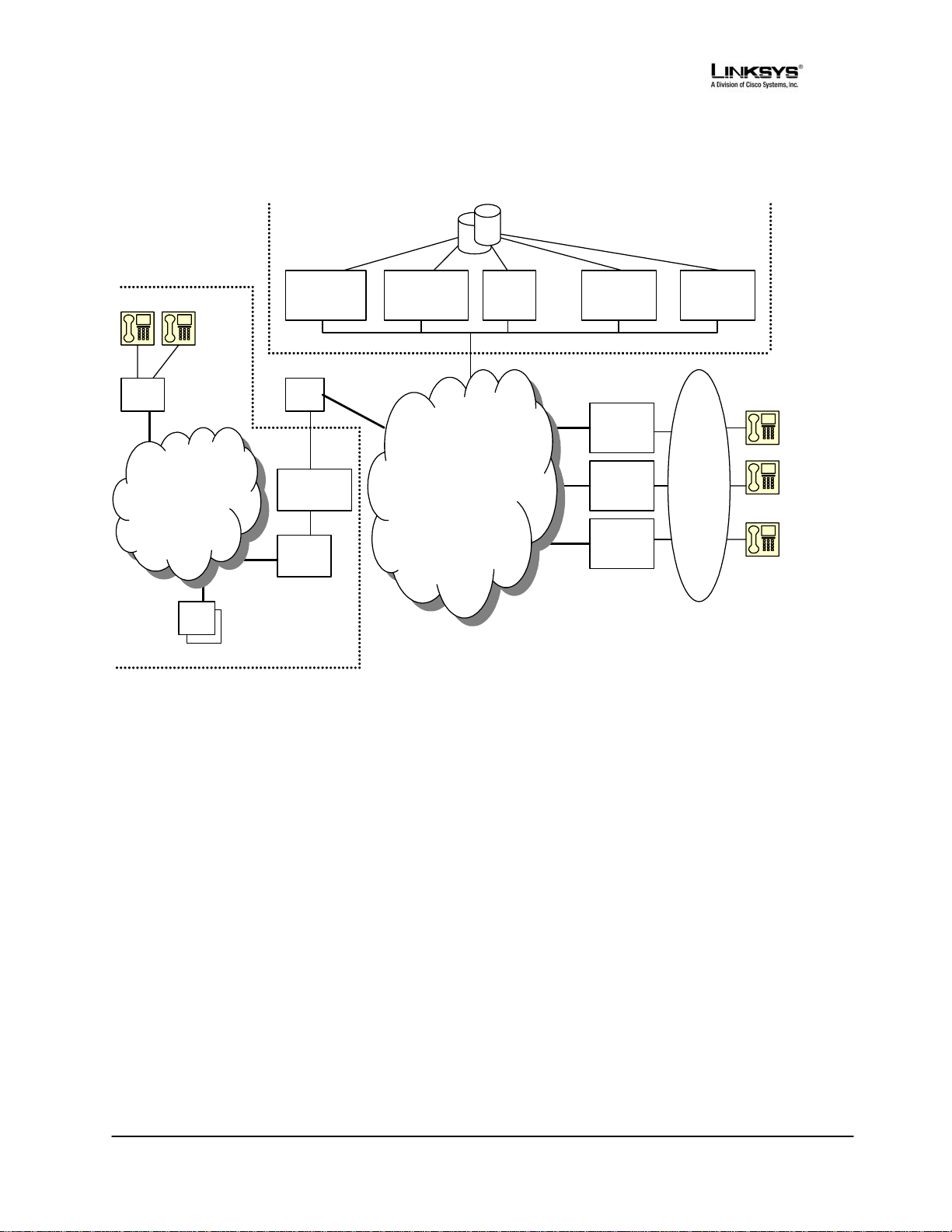
1.3.2. Components of a SIP Network
SPA
Private IP
Network
PC
PC
Service
Provider
Domain
Provisioning
Server
ISP
Broadband
Modem
Router
NAT
Subscriber
Domain
SIP
Proxy Server
IP
Network
(Internet)
Subscriber
Database
Billing
Server
Application
Server
PSTN
Gateway
PSTN
Gateway
PSTN
Gateway
Application
Server
PSTN
Figure 1 -- Components of a SIP IP Telephony Network
IP Telephony Gateway (SPA): The SPA is a small device that sits at the subscriber’s premises. It
converts between analog telephone signals and IP Telephony signals. It has up to two RJ-11 ports
where standard analog telephones can be directly attached, and an RJ-45 interface for the Ethernet
connection to the home or business LAN. Intelligence can be built into this device to provide a wide
range of features to the subscribers in association with the other elements in the service. The SPA
functions as a SIP User Agent (UA).
Home/SOHO Routers with NAT Functionality: A home/SOHO router is used for routing IP packets
between the subscriber’s private network and the ISP’s public network. If the ISP provides only one
public IP address to the subscriber, the devices attached to the private network will be assigned
private IP addresses and the router will perform network address translation (NAT) on packets sent
from the private network to the public network via the router. Home routers offer the following
features:
• An R-J45 WAN interface for connection to the ISP’s public network and one or more RJ-45
LAN interfaces for connection to the subscriber’s private network. The router directs
packets between the private network and the public network.
• A PPPoE client to connect with the ISP through a DSL modem.
• A DHCP client where the router will obtain an IP address, subnet mask, default router
assignment, etc., for its WAN interface from a DHCP server on the public network.
• A DHCP server for auto-assignment of private IP addresses, subnet mask, and default
router assignment to devices attached to the private network, i.e. computers, IP Telephony
© 2003 - 2005 Sipura Technology, Inc Proprietary (See Copyright Notice on Page 2)
© 2005 - 2006 Linksys, A Division of Cisco Systems, Inc.
10
Page 11

gateways, etc. The default router in this case is the IP address of the LAN interface of the
router itself.
• Performs NAT on packets sent from the private network to the public network. This is an
important feature such that recipients of the private packets will perceive them as originated
from a public IP address (the router’s WAN interface) and will therefore return messages to
the proper public IP address and port. Different routers may use different rules for
allocating port numbers at the WAN interface to forward packets from a private IP
address/port to a public IP address/port. The allocated port number is also used for routing
packets from external IP addresses to a private address. Most routers will accept a number
of static port mapping rules for forwarding packets received on a specific port at the WAN
interface to a specific IP address/port in the private network.
PSTN - VoIP Gateways: These devices are required if user agents are expected to make calls to or
receive calls from the PSTN. Many gateways may be deployed in order to service a wide area.
Gateways also behave like SIP user agents. The proxy server can be configured with cost-saving
rules based call routing information so that it may decide which gateway to use depending on the
destination and the time of the call. The IP Telephony service provider will assign each subscriber an
E164 telephone number so that it may be reached from the PSTN just like any other telephone.
Billing Servers: Billing servers are used to generate billing data per usage of the IP Telephony
service. Typically, the service provider will charge a flat fee for unlimited calls between IP Telephony
subscribers (on-net-to-on-net calls). Per use or minute chargers will be incurred only when the
subscriber makes calls to PSTN numbers (on-net-to-off-net calls) through one of the PSTN gateways.
CDR (call detail record) data are generated by the PSTN gateway and sent to the billing servers.
Provisioning Servers: Provisioning servers are used to provision the subscriber user agent devices,
e.g. the SPA. When a subscriber signs up for IP Telephony service, he selects an appropriate service
level and enters his personal information including billing information. This information is processed
by the provisioning server and stored into the service provider’s customer database. The provisioning
server generates a device profile based on the subscriber’s choice of options. The device profile,
which is list of configuration parameters, is downloaded into the SPA from the provisioning server.
The SPA can be configured to contact the provisioning server periodically to check for any update of
the device profile, which may include a firmware upgrade or configuration modification to the SPA.
Application Servers: Application servers are used to provide value added services, such as call
forwarding, outgoing or incoming call blocking
Voice Mail Servers: Specialized servers provide voice mail services to the IP Telephony service
subscribers. When the subscriber is busy or the SPA is out of service for maintenance or other
reason, incoming calls to the subscriber may be redirected to the voice mail servers where the caller
can leave a voice mail. The voice mail server will then notify the subscriber’s SPA of the availability of
voice mail(s) in his mailbox. The subscriber can then contact the voice mail server to retrieve his
voice mail(s). The SPA can indicate the message-waiting status to the subscriber through a number
of methods such as stuttered dial tone heard through the telephone every time the subscriber lifts up
the handset until the voice mail is retrieved.
1.3.3. Provisioning Overview
The SPA is configurable in many ways such that it can provide a wide range of customizable services
and operate in many diverse environments with a variety different vendors’ SIP Proxy Servers, VoIP
Gateways, Voice Mail Servers, NAT applications, etc. Provisioning is the process by which the SPA
obtains a set of configuration parameters in order for it to operate in the Service Provider’s network.
The complete set of configuration parameters for an SPA corresponding to an individual subscriber is
referred to as a configuration profile or simply a Profile. The Profile can be encoded as an XML file or
a simple plain text file with a list of tag/value pairs. When the SPA unit is shipped from the factory, it
contains a default common Profile and is considered Unprovisioned. To save costs and expedite
© 2003 - 2005 Sipura Technology, Inc Proprietary (See Copyright Notice on Page 2)
© 2005 - 2006 Linksys, A Division of Cisco Systems, Inc.
11
Page 12

delivery, however, it is very desirable that an Unprovisioned unit can be shipped directly from the
factory to the subscriber’s location without any preprocessing by the Service Provider.
The SPA contacts the Service Provider’s provisioning server via the IP network or Internet when it is
plugged into the subscriber’s home or business Local Area Network (LAN) – assuming the
provisioning server is reachable from the subscriber’s home network – to pull the designated profile to
be installed in that particular SPA unit. Furthermore, the SPA unit will periodically contact the
provisioning server to download an updated profile. The protocol for downloading the configuration
profile can be “clear text” TFTP or HTTP data or it can be encrypted TFTP, HTTP or HTTPS data if
security is required. Security will be discussed in more details in a later section.
This type of autonomous remote provisioning, where the individual SPA unit pulls the profile from the
provisioning server is very scalable and flexible. Using this provisioning method, a large number of
SPA units can be provisioned simultaneously and updated periodically.
However, some basic information must be provided to the SPA before it can be provisioned in this
fashion: a) the IP address or domain name of the provisioning server to contact, and b) an ID and/or a
password to send to the provisioning server such that it can associate it with a specific subscriber and
obtain the corresponding profile. This information can be sent out-of-band to the subscriber via
secured email or in a letter inside a welcome kit, for example. The subscriber might need to punch in
some numbers using a telephone connected to the SPA in order to enter this information into the unit.
The SPA provides an easy-to-use interface with audio instructions to make this initial configuration
process as painless as possible. An alternative is for the unit to be provisioned with this basic
information by the Service Provider before the unit is shipped to the subscriber.
In addition to the batch mode of remote provisioning, the SPA allows an interactive mode of local
provisioning. One way to offer this feature is through the use of an IVR system (accessed through an
attached telephone set). The user can access a diagnostic or configuration menu to check the status
of the device or to change some of the settings. This method of provisioning may be applied by an
administrator when the device is at the Service Provider’s office, or by the subscriber under the
guidance of trained personnel during over-the-phone troubleshooting.
A third method of entering provisioning information into the SPA is by way of its integral web server
via a browser on a PC. The subscriber has the option to set and adjust configuration parameters via
an easy-to-use, password protected graphical user interface. This method of provisioning might be
preferred by administrators who wish to access the SPA over a secure corporate/institutional LAN or
by the residential subscriber who is a “power user.”
1.3.4. Security Overview
Security may be applied at many levels in the context of the SPA. The following are examples of
information that should be secured:
• The configuration profile pulled from the provisioning server – The downloading of the
profile should be secured since it contains authentication (password/user name ID /
number) information for accessing subscriber telephony services. It may also contain other
passwords and/or encryption keys used for a variety of management and service
operations.
• The administration password to the SPA unit – The unit must disallow access to
administrative functions to unauthorized users. This access can be controlled with an
administrator password. The administrator password can be one of the parameters in the
SPA configuration profile.
• The SIP signaling messages – The SIP messages exchanged between the SIP proxy
server and the SPA should be encrypted with a secret key. This can be achieved, for
instance, by transporting SIP over TLS.
© 2003 - 2005 Sipura Technology, Inc Proprietary (See Copyright Notice on Page 2)
© 2005 - 2006 Linksys, A Division of Cisco Systems, Inc.
12
Page 13

• RTP packets – The RTP payload exchanged between SIP user agents can be encrypted
with a secret key to protect against eavesdropper. The secret key can be negotiated with
proper SIP signaling messages. Hence the signaling path must be secured also.
1.3.4.1. Proxy Servers
Proxy servers handle two functions:
1. Accept registrations from the SIP user agents,
2. Proxy requests and responses between user agents.
Registration is the process by which a user agent tells the proxy who it is and at what IP address and
port that it can be reached via SIP. Registration usually expires within a finite period (e.g., 60s or
3600s) and the UA shall renew their registration periodically before the last registration expires. When
a user agent initiates a call, it sends a SIP INVITE request to the proxy server and indicates the target
recipient of the call. The proxy server then consults a database to determine where to forward the
request to the destination user agent. The proxy server can request authentication credentials from
the user agent before granting the service. The credentials are computed by the user agent based on
a pre-provisioned password and a challenge “nonce” dynamically generated by the proxy server per
request. This mechanism prevents unauthorized user agents from getting IP Telephony services
through the proxy server. SIP proxy servers are operated by the IP Telephony service provider and
resides at the service provider’s domain. They may be implemented in many different ways. They can
be stateless, stateful, or B2BUA. Stateless proxies do not maintain states of each call; they simply
proxy the requests and responses between the user agents. Hence they are the simplest, most
scalable, but provide the least types of services. Advanced IP Telephony services are possible with
these proxies only with intelligent user agent devices that are capable of delivering these services
without proxy intervention. Stateful proxies maintain the call state of each call and can provide more
intelligent services at the expense of more processing load per call. B2BUA proxies process every
request and response from the user agents and are capable of providing very advance services even
with relatively simple user agent devices. Obviously B2BUA proxies have the highest processing load
per call.
1.3.5. SIP Services
Today’s PSTN offers a large number of enhanced services in addition to basic phone services. Most
of the services offered by the PSTN are accessed by the subscribers through their telephone sets.
The subscribers provide their input by talking into the handset, pressing the keypad, the switch hook
or flash button, while the PSTN presents instructions/information/confirmation to the subscribers
through a variety of audio tones, beeps and/or announcements. The SPA supports a comparable
range of services via a similar user interface in order to make the IP Telephony service transparent to
subscribers.
The SPA is fully programmable and can be custom provisioned to emulate just about any traditional
telephony service available today. This ability to transparently deliver legacy services over an IP
network coupled with the availability of Internet connected devices (PCs. PDA, etc.) and browsers
opens up a new world of potential offerings that a provider can use to differentiate their service and
grow their business.
The following is a list of commonly supported phone services:
1.3.5.1. Basic Services
1.3.5.1.1. Making Calls to PSTN and IP Endpoints
This is the most basic service. When the user picks up the handset, the SPA provides dial tone and is
ready to collect dialing information via DTMF digits from a touch tone telephone. While it is possible to
support overlapped dialing within the context of SIP, the SPA collects a complete phone number and
© 2003 - 2005 Sipura Technology, Inc Proprietary (See Copyright Notice on Page 2)
© 2005 - 2006 Linksys, A Division of Cisco Systems, Inc.
13
Page 14

sends the full number in a SIP INVITE message to the proxy server for further call processing. In
order to minimize dialing delay, the SPA maintains a dial plan and matches it against the cumulative
number entered by the user. The SPA also detects invalid phone numbers not compatible with the
dial plan and alerts the user via a configurable tone (reorder) or announcement.
1.3.5.1.2. Receiving Calls from PSTN and IP Endpoints
The SPA can receive calls from the PSTN or other IP Telephony subscribers. Each subscriber is
assigned an E.164 phone number so that they may be reached from wired or wireless callers on the
PSTN. The SPA supplies ring voltage to the attached telephone set to alert the user of incoming calls.
1.3.5.2. Enhanced Services
Enhanced Services are provided in addition to Basic calling services and accessed by way of a
touchtone phone through a series of menus. Since the service enabled by the SPA are Internet in
nature, these enhanced services can be made better by offering users a web browser based interface
to control certain aspects of some or all services.
1.3.5.2.1. Caller ID
In between ringing bursts, the SPA can generate a Caller ID signal to the attached phone when the
phone is on-hook.
1.3.5.2.1.1. Calling Line Identification Presentation (CLIP)
Some subscribers will elect to always block their Caller ID information, yet there may be a
circumstance where sending Caller ID information for a particular call is desired, i.e. trying to reach a
party that does not accept Caller ID blocked calls.
The subscriber activates this service to send his Caller ID when making an outgoing call. To activate
the service, the subscriber enters the corresponding * or # code prior to making the call. This service
is in effect only for the duration of the current call.
1.3.5.2.1.2. Calling Line Identification Restriction (CLIR) – Caller ID Blocking
The subscriber activates this service to hide his Caller ID when making an outgoing call. To activate
the service, the subscriber enters the corresponding * or # code prior to making the call. This service
is in effect only for the duration of the current call.
1.3.5.2.2. Call Waiting
The subscriber can accept a call from a 3rd party while engaging in an active call. The SPA shall alert
the subscriber for the 2nd incoming call by playing a call waiting tone.
1.3.5.2.2.1. Disable or Cancel Call Waiting
By setting the corresponding configuration parameter on the SPA, the SPA supports disabling of call
waiting permanently or on a per call basis.
1.3.5.2.2.2. Call-Waiting with Caller ID
In between call waiting tone bursts, the SPA can generate a Caller-ID signal to the attached phone
when it is off hook.
1.3.5.2.3. Voice Mail
1.3.5.2.3.1. Message Waiting Indication
Service Providers may provide voice mail service to their subscribers. When voice mail is available
for a subscriber, a notification message will be sent from the Voice Mail server to the SPA. The SPA
indicates that a message is waiting by, playing stuttered dial tone (or other configurable tone) when
the user picks up the handset.
1.3.5.2.3.2. Checking Voice Mail
© 2003 - 2005 Sipura Technology, Inc Proprietary (See Copyright Notice on Page 2)
© 2005 - 2006 Linksys, A Division of Cisco Systems, Inc.
14
Page 15

The SPA allows the subscriber to connect to their voice mail box by dialing their personal phone
number.
1.3.5.2.4. Call Transfer
Three parties are involved in Call Transfer: The transferor, transferee, and transfer target. There are 2
flavors of call transfer: Attended Transfer (Transfer with consultation) and Unattended Transfer
(“Blind” Transfer).
1.3.5.2.4.1. Attendant Transfer
The transferor dials the number of the transfer target, then he hangs up (or enters some * or # code)
when the transfer target answers or rings to complete the transfer.
1.3.5.2.4.2. Unattended or “Blind” Transfer
The transferor enters some * or # code and then dials the number of the transfer target to complete
the transfer (without waiting for the target to ring or answer).
1.3.5.2.5. Call Hold
Call Hold lets you put a caller on hold for an unlimited period of time. It is especially useful on phones
without the hold button. Unlike a hold button, this feature provides access to a dial tone while the call
is being held.
1.3.5.2.6. Three-Way Calling
The subscriber can originate a call to a 3rd party while engaging in an active call.
1.3.5.2.7. Three-Way Ad-Hoc Conference Calling
The SPA can host a 3-way conference and perform 3-way audio mixing (without the need of an
external conference bridge device or service).
1.3.5.2.8. Call Return
The SPA supports a service that allows the SPA to automatically dials the last caller’s number.
1.3.5.2.9. Call Return on Busy
If the last called number is busy, the subscriber can order this service to monitor the called party and
to receive a notification from the SPA (such as special phone ring) when that party becomes
available.
1.3.5.2.10. Automatic Call Back
This feature allows the user to place a call to the last number they tried to reach whether the call was
answered, unanswered or busy by dialing an activation code.
1.3.5.2.11. Call Forwarding
These services forward all the incoming calls to a static or dynamically configured destination number
based on three different settings. These services may be offered by the SPA or by the SIP proxy
server. They can be activated by entering certain * or # code, followed by entering a telephone
number to forward calls to. The SPA provides audio instructions to prompt the user for a forwarding
number and confirms that the requested service has been activated.
1.3.5.2.11.1. Call FWD – Unconditional
All calls are immediately forwarded to the designated forwarding number. The SPA will not ring or
provide call waiting when Call FWD – Unconditional is activated.
1.3.5.2.11.2. Call FWD – Busy
Calls are forwarded to the designated forwarding number if the subscriber’s line is busy because of
the following; Primary line already in a call, primary and secondary line in a call or conference.
© 2003 - 2005 Sipura Technology, Inc Proprietary (See Copyright Notice on Page 2)
© 2005 - 2006 Linksys, A Division of Cisco Systems, Inc.
15
Page 16

1.3.5.2.11.3. Call FWD - No Answer
Calls are forwarded to the designated forwarding number after a configurable time period elapses
while the SPA is ringing and does not answer.
1.3.5.2.12. Anonymous Call Blocking
By setting the corresponding configuration parameter on the SPA, the subscriber has the option to
block incoming calls that do not reveal the caller’s Caller ID.
1.3.5.2.13. Distinctive / Priority Ringing
The SPA supports a number of ringing and call waiting tone patterns to be played when incoming
calls arrive. The choice of alerting pattern to use is carried in the incoming SIP INVITE message
inserted by the SIP Proxy Server (or other intermediate application server in the Service Provider’s
domain).
1.3.5.2.14. Speed Dialing
The SPA supports speed dialing of up to eight (8) phone numbers or IP addresses. To enter a
telephone number speed dial using a touch tone telephone, the user dials a feature code (*74),
followed by a number (2-9), then the destination speed dialed target number. When the user wishes
to speed dial a target number, they press the corresponding speed dial assigned number followed by
the “#” (pound) key.
Users may also enter/review speed dials from User1/User2 web-pages. This interface or similar is
required to enter IP address targets.
1.3.5.3. PSTN Interworking
The SPA is designed to provide a transparent interworking relationship with the PSTN. Service
providers can deploy the SPA in such a way that PSTN endpoints – wired or wireless –
communicating with SPA endpoints do so without modification to their configuration or network
settings.
The service provider may choose to deploy a multi-protocol VoIP network, much the same way the
PSTN supports multiple signaling schemes today. Most telecommunication providers operate
equipment that supports CAS or channel associated signaling, ISDN signaling and SS7 signaling.
When VoIP is introduced or used in the telecommunications landscape, it is likely that the service
provider will implement a signaling gateway that supports multiple IP Telephony protocols along with
legacy PSTN protocols. The signaling gateway is commonly referred to as a Softswitch.
Architecture and functionality can vary greatly amongst the different softswitch vendors. The
protocols used will depend on the types of connections that will be set-up across the service
provider’s network. If the provider is simply providing transport of calls to/from their network to
another provider’s network, but not originating or terminating calls with the endpoints, SIP will likely
be used for softswitch to softswitch communication.
If the service provider is offering origination and/or termination on endpoint equipment then it is very
likely that the softswitch chosen for network operations will support multiple PSTN and VoIP signaling
protocols.
The table below lists the most commonly accepted, de-facto standards used when implementing a
VoIP signaling scheme based on the type of gateway or endpoint equipment being deployed:
VoIP Equipment Type Typical Port Density De-Facto Signaling Standards
Trunking Gateways Greater Than 500 Ports H.248-Megaco / MGCP / IPDC
Access Gateways Between five and 500 Ports SIP / H.323
© 2003 - 2005 Sipura Technology, Inc Proprietary (See Copyright Notice on Page 2)
© 2005 - 2006 Linksys, A Division of Cisco Systems, Inc.
16
Page 17

PBX/KTS Platforms Between ten and 500 Ports SIP / H.323 / SCCP
PBX/KTS Telephone Sets One Port SIP / MGCP / SCCP
Phone Adapters and IP Centrex
Up to four Ports SIP / MGCP
Phones
The SPA supports SIP today. It has the capability to communicate with a variety of endpoints and
signaling entities via SIP messages.
1.4. Network Address Translation (NAT) Traversal
1.4.1. Why NAT?
A NAT allows multiple devices to share the same external IP address to access the resources on the
external network. The NAT device is usually available as one of the functions performed by a router
that routes packets between an external network and an internal (or private) one. A typical application
of a NAT is to allow all the devices in a subscriber’s home network to access the Internet through a
router with a single public IP address assigned by the ISP. The IP header of the packets sent from
the private network to the public network can be substituted by the NAT with the public IP address
and a port selected by the router according to some algorithm. In other words, recipient of the packets
on the public network will perceive the packets as coming from the external address instead of the
private address of the device where the packets are originated.
In most Internet protocols, the source address of a packet is also used by the recipient as the
destination to send back a response. If the source address of the packets sent from the private
network to the public network is not modified by the router, the recipient may not be able to send back
a response to the originator of the message since its private source IP address/port is not usable.
When a packet is sent from a device on the private network to some address on the external network,
the NAT selects a port at the external interface from which to send the packet to the destination
address/port. The private address/port of the device, the external address/port selected by the NAT to
send the packet, and the external destination address/port of the packet form a NAT Mapping.
The mapping is created when the device first sends a packet from the particular source address/port
to the particular destination address/port and is remembered by the NAT for a short period of time.
This period varies widely from vendor to vendor; it could be a few seconds, or a few minutes, or more,
or less. While the mapping is in effect, packets sent from the same private source address/port to the
same public destination address/port is reused by the NAT. The expiration time of a mapping is
extended whenever a packet is sent from the corresponding source to the corresponding destination.
More importantly, packets sent from that public address/port to the external address/port of the NAT
will be routed back to the private address/port of the mapping session that is in effect. Some NAT
devices actually reuse the same mapping for the same private source address/port to any external IP
address/port and/or will route packets sent to its external address/port of a mapping from any external
address/port to the corresponding private source address/port. These characteristics of a NAT can be
exploited by an SPA to let external entities send SIP messages and RTP packets to it when it is
installed on a private network.
1.4.2. VoIP-NAT Interworking
In the case of SIP, the addresses where messages/data should be sent to an SPA are embedded in
the SIP messages sent by the device. If the SPA is sitting behind a NAT, the private IP address
assigned to it is not usable for communications with the SIP entities outside the private network. The
SPA must substitute the private IP address information with the proper external IP address/port in the
mapping chosen by the underlying NAT to communicate with a particular public peer address/port.
For this the SPA needs to perform the following tasks:
© 2003 - 2005 Sipura Technology, Inc Proprietary (See Copyright Notice on Page 2)
© 2005 - 2006 Linksys, A Division of Cisco Systems, Inc.
17
Page 18
• Discover the NAT mappings used to communicate with the peer. This could be done with
the help of some external device. For example a server could be deployed on the external
network such that the server will respond to a special NAT-Mapping-Discovery request by
sending back a message to the source IP address/port of the request, where the message
will contain the source IP address/port of the original request. The SPA can send such a
request when it first attempts to communicate with a SIP entity in the public network and
stores the mapping discovery results returned by the server.
• Communicate the NAT mapping information to the external SIP entities. If the entity is a
SIP Registrar, the information should be carried in the Contact header that overwrites the
private address/port information. If the entity is another SIP UA when establishing a call,
the information should be carried in the Contact header as well as in the SDP embedded in
SIP message bodies. The VIA header in outbound SIP requests might also need to be
substituted with the public address if the UAS relies on it to route back responses.
• Extend the discovered NAT mappings by sending keep-alive packets. Since the mapping is
only alive for short period, the SPA continues to send periodic keep-alive packets through
the mapping to extend its validity as necessary.
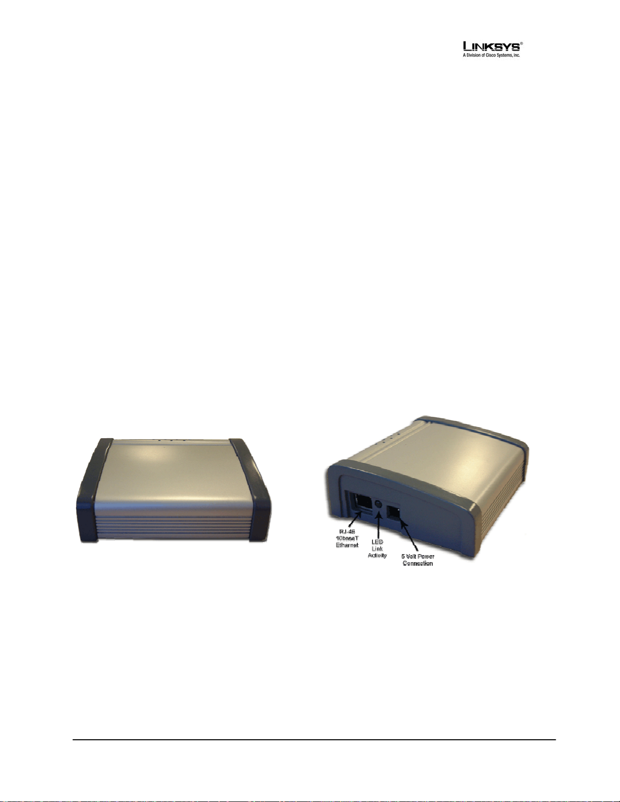
1.5. SPA Hardware Overview
The SPA has one of the smallest form factors on the market. It can be installed in minutes as a tabletop or wall mount CPE device. The images below show the SPA-2000. The SPA-1000 and SPA3000 are similar to size and shape – the only difference being the color of the adapter.
Figures Figure 2, Figure 3, Figure 4 and Figure 5 show the front, rear, left side and right side of the
SPA-2000, respectively.
Figure 2 – SPA-2000 Front
Figure 3 – SPA-2000 Left Side
© 2003 - 2005 Sipura Technology, Inc Proprietary (See Copyright Notice on Page 2)
© 2005 - 2006 Linksys, A Division of Cisco Systems, Inc.
18
Page 19
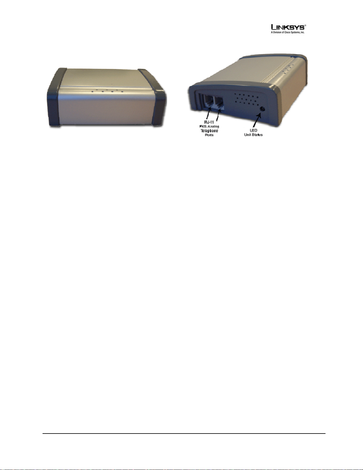
Figure 4 – SPA-2000 Rear
Figure 5 – SPA-2000 Right Side
The SPA has the following interfaces for networking
1. Two (2) RJ-11 Type Analog Telephone Jack Interfaces (Figure
These interfaces accept standard RJ-11 telephone connectors. An Analog touchtone tele
fax machine may be connected to either interface. If the service supports only one incomin
analog telephone or fax machine should be connected to port one (1) of the SP
outermost telephone port on the SPA and is labeled “Phone 1.”
The SPA-3000 has an RJ-11 interface labeled “Line” which can be used to connect the adapter
PSTN analog telephone circuit.
2. One LED for Un
This LED indicates status via the following behaviors:
ON – LED remains solid on
OFF – LED remains solid o
LONG (Long On) – 3.0s on, 1s off contin
FAST – 0.1s on, 0
SLOW – 0.5s on, 0.5s off continuously
VSLO (Very Slow) – 1.0s on,
HB (Heart Beat) – 0.1s on, 0.1
HB2 (Heart Beat 2) - 0.1s on, 0.1s off, 0.1s on, 0.1s
it Status (Figure 5, above):
ff
uously
.1s off continuously
1.0s off continuously
s off, 0.1s on, 1s off continuously
, power and visual status indication:
5, above):
phone or
g line, the
A. Port one (1) is the
off, 0.1s on, 1.2s off continuously
to a
ERR0(Error 0) - 0.5s on, 0.3s off, 0.1s on, 0.1s
ERR1(E tinuously
ERR2(Error 2) – 0.1s on, 0.1s off, 0.1s on
3. One Ethernet 1
Figure 3, above):
his interface accepts a standard or crossover Ethernet cable with standard RJ-45 connector. For
T
optimum performance, Linksys recom
conjunction with the SPA.
© 2003 - 2005 Sipura Technology, Inc Proprietary (See Copyright Notice on Page 2)
© 2005 - 2006 Linksys, A Division of Cisco Systems, Inc.
rror 1) – 0.1s on, 0.1s off, 0.1s on, 0.1s off, 0.5s on, 2s off con
0baseT RJ-45 Jack Interface (
off, 0.1s on, 2s off continuously
, 0.1s off, 0.5s on, 0.2s off, 0.5s on, 2s off continuously
mends that a Category 5 cable or greater be used in
19
Page 20

4. One LED for Data Link and Activity (
Figure 3, above):
This LED indicates status via the following
ON – LED remains solid o
OFF – LED remains solid
FAST – 0.125s on, 0
SLOW – 0.5s on, 0.5s off continuously
Variable Blink – LED blinks according to packet traffi
5. One 5 Volt Power Adapter Interface (
igure 3, above)
F
This interface accepts the SPA power adapter that came with the unit.
use of any other power adapters other then the power adapter that was shipped
n
off
.125s off continuously
behaviors:
c activity
Linksys does not support the
2. Installation Overview
Please check to make sure that you have the following package contents:
1. Linksys Phone Adapter Unit
2. Ethernet Cable
J-11 Phone Cable (SPA-3000 Only)
3. R
4. SPA Quickstart Guide
5. 5 Volt Power Adapter
You will also need:
1. One or Two Analog Touch Tone Telephones (or Fax Machine)
2. Acc
ess to an IP Network via an Ethernet Connection
with the SPA unit.
. Access to a PSTN network connection – SPA-3000 only.
3
Please observe the following steps to i
From the Left Side of the S
1. Insert a standard RJ-45 Ethernet cable (included) into the LAN port.
2. Insert the power adapter cable into the 5V power adapter cable receptacle.
Ensure that the power adapter jack is snugly attached to the SPA.
From the
1. Insert a standard RJ-11 telephone cable
. Connect the other end of the cable to an analog telephone or fax machine.
2
3. Insert a st
4. Connect the other end of the cable to a
Note: Do not connect RJ-11 telephone cable from the SPA-1000 or SPA-2000 to the wall jack to
prevent any chance of connection to the circuit switched telco network.
You may now insert the plug end of the power adapter into a live power outlet which will power up the
SPA.
© 2003 - 2005 Sipura Technology, Inc Proprietary (See Copyright Notice on Page 2)
© 2005 - 2006 Linksys, A Division of Cisco Systems, Inc.
Right Side of the SPA:
andard RJ-11 telephone cable into the Phone 2 port (Optional).
PA:
nstall the SPA.
into the Phone 1 port.
n analog telephone or fax machine.
20
Page 21

3. Software Configuration
3.1. Provisioning
Please refer to the Linksys SPA Provisioning Guide document for information pertaining to
• HTTPS provisioning features available (starting with Sipura / Linksys release 2.0).
• Setting up a provisioning system for a large number of Linksys anal og telephone adapters.
• Complete list of provisioning parameters.
3.1.1. Provisioning Capabilities
The SPA provides for secure provisioning and remote upgrade. Provisioning is achieved through
configuration profiles transferred to the device via TFTP, HTTP or HTTPS. The SPA can b
configured to resync its internal configuration state to a remote profile periodically and on power up.
e
Starting
a
with firmware release 2.0 256-bit symmetric key encryption of profiles is supported. In
ddition, an unprovisioned SPA can receive an encrypted profile specifically targeted for that device
without requiring an explicit key. Version 2.0 supports a secure first-time provisioning mechanism
using SSL functionality. This functionality is explained later in this section.
Remote firmware upgrade is achieved via TFTP or HTTP. Firmware upgrades using HTTPS are
supported. The SPA upgrade logic is capable of automating multi-stage upgrades, in
ntermediate upgrades are ever i
required to reach a future upgrade state from an older release.
General purpose parameters are provided as an additional aid to service providers in managing th
not
case
e
provisioning process.
All profile resyncs are attempted only when the SPA is idle, since they may trigger a software reboot.
User intervention is not required to initiate or complete a pro
file update or firmware upgrade.
3.1.2. Configuration Profile
The SPA configuration profile is a binary file with enco
ermissions for those parameters. By convention, the profile is named with the extension “.cfg” (e.g.
p
spa2000.cfg). The Linksys Profile Compiler tool (SPC) is provided for compiling a plain-text file
containing parameter-value pairs into a properl
vailable from Linksys for the Win32 environment (spc.exe), Linux-i386-elf environment (spc-linux-
a
y formatted and encrypted CFG file. The spc tool is
i386-static). Availability of the SPC tool for the OpenBSD environment is available on a case-by-case
basis.
The syntax of the plain-text file accepted by the release 2.0 profile compiler is a series of parameter
value pairs, with the value in double quotes. Eac
e.g. parameter_name “parameter_value”;. If no quoted value is specified for a parame
parameter specification is missing entirely from the plain-text file) the value of the parameter will
r m
e ain unchanged in the SPA.
The syntax also controls the parameter’s user-level access when using the built-in web interfa
the SPA. An optional exclamation point or question mark, immediately following the parameter name,
dicates thein
resent, the parameter is made inaccessible to the user from the web interface. Note that this syntax
p
parameter should be user read-write or read-only, respectively. If neither mark is
has no effect on the admin-level access to the parameters.
this way, a service provider is given full control over which parameters become inaccessible, read-
In
only, or read-write following provisioning of the SPA.
ded SPA parameter values and user access
-
h parameter-value pair is followed by a semicolon,
ter (or if a
ce to
© 2003 - 2005 Sipura Technology, Inc Proprietary (See Copyright Notice on Page 2)
© 2005 - 2006 Linksys, A Division of Cisco Systems, Inc.
21
Page 22

If the parameter specification is missing entirely from the plain-text file, the user-level access to the
parameter will remain unchanged
in the SPA.
If the plain-text file contains multiple occurrences of the same p
arameter-value specification, the last
such occurrence overrides any earlier ones.
Parameter names in the plain-text file must match the corresponding nam
es appearing in the SPA
web interface, with the following modifications:
• Inter-word spaces are replaced by underscores ‘_’ (e.g. Multi_Wo rd_Param
• For the SPA, line and user specific parameters use bracketed index syntax to identify
eter).
which line
or user they refer to (e.g. Line_Enable[1] and Line_Enable[2]).
Comments are delimited by a ‘#’ character up to the end-of-line. Blank lines can be used for
readability.
Parameter_name [ ‘?’ | ‘!’ ] [“quoted_parameter_value_string”] ‘;’
seBoolean parameter values are as rted by any one of the values {Yes | yes | Enable | enable | 1}.
They are deasserted by any one
xampleE
of plain-text file entries:
of the values {No | no | Disable | disable | 0}.
# These parameters are for illustration only
Feature_Enable ! “Enable” ; # user read-write
Another_Parameter ? “3600” ; # user read-only
Hidden_Parameter “abc123” ; # user not-accessible
Some_Entry ! ; # user read-write, leave value unchanged
plain text files can be splMultiple iced together to generate the source for each CFG file. This is
accomplished by the “import” directive: the literal
file namefollowed by one or more spaces and the
wing example illustrates. File spThe follo
licing can be nested several files deep.
string “import” (placed at the start of a new line)
to splice into the stream of parameter-value pairs.
# base.txt contains . . .
Param1 “base value 1” ;
Param2 “base value 2” ;
. . .
# spa1234.txt contains . . .
import base.txt
Param1 “new value overrides base” ;
Param7 “particular value 7” ;
. . .
# The spa1234.txt file above is equivalent to . . .
© 2003 - 2005 Sipura Technology, Inc Proprietary (See Copyright Notice on Page 2)
© 2005 - 2006 Linksys, A Division of Cisco Systems, Inc.
22
Page 23

Param1 “base value 1” ;
Param2 “base value 2” ;
. . .
Param1 “new value overrides base” ;
Param7 “particular value 7” ;
. . .
A sample plain-text file, containing default parameter-value and access settings for the SPA can
btained from
the profile compiler tool, using the following command-line arguments. o
be
spc –-sample-profile defaults.txt
Once a plain-text file has been generated with the desired parameter settings, it needs to be compiled
into a binary CFG file. The profile compiler can generate a generic unencrypted CFG file, a targeted
CFG file (encrypted for a unique SPA), a generic key encrypted CFG file, or a targeted and key
ncryptee
d CFG file.
A generic CFG file (non-targeted) is accepted as valid by any SPA d
accepted as valid by the SPA device bearing the target MAC addres
ncrypted with a 128-bit algorithmically generated key, and therefore do not require a key to be
e
evice. A targeted CFG file is only
s. Targeted CFG files are
issued explicitly. Targeted CFG files provide a basic level of security for remotely locking an
otherwise unprovisioned SPA.
Firmware version 2.0 uses symmetric key encryption. Using HTTPS, an SSL chann
el can be used
for initial secure remote provisioning using asymmetric key encryption.
Firmware 2.0 supports RC4 and AES symmetric key algorithms, with keys of up to 256 bi
can be specified explicitly as a hex-string, or it can be generated from a password
se. In the case of passwords and pass-phrases, the internally generated key is 128 bits in
phra
ts. The key
or a quoted pass-
length.
he following command-line syntax generates a generic and unencrypted CFG file:
T
spc spa2000.txt spa2000.cfg
A targeted CFG file (with basic encryption) is specified by supplying the MAC address of the target
device:
spc –-target 000e08aaa010 spa2000.txt spa2000.cfg
An encrypted CFG file requires either a password (or quoted pass-phrase) or a hex-string. The
following lines illustrate command-line invocations for various combinations of keys and algorithms.
spc –-rc4 –-ascii-key apple4sale spa2000.txt spa2000.cfg
spc –-aes –-ascii-key lucky777 spa2000.txt spa2000.cfg
spc –-aes –-ascii-key “my secret phrase” spa2000.txt spa2000.cfg
© 2003 - 2005 Sipura Technology, Inc Proprietary (See Copyright Notice on Page 2)
© 2005 - 2006 Linksys, A Division of Cisco Systems, Inc.
23
Page 24

spc –-aes –-hex-key 8d23fe7...a5c29 spa2000.txt spa2000.cfg
A CFG file can be both targeted and key encrypted, as suggested by the following example:
spc 010 –-aes –-hex-key 9a20...eb47 a.txt a.cfg –-target 000e08aaa
The can be suppressed with the “--quiet” command line option. Or
status messages printed by spc
they le, with the “--log file_name” command line option. In the latter case, the
can be redirected to a fi
spc also printed in the log file, preceded by a timestamp.
command line invocation itself is
spc –-quiet . . .
spc –-log prov.log . . .
An alternative profile syntax using XML is described in the Linksys SPA Provisioning Guide. XML
profiles can be fed to the SPA in a resync operation without the need to compile them first into a
bina
ry object.
3.1.3. Provisioning Parameters
The ribed in this section represent a basic subset of all parameters available to
parameters desc
control provisioning and remote upgrades. Please refer to the Linksys SPA Provisioning Guide for a
omp n of all available parameters.
c rehensive descriptio
rovisioning is controlleP
section).
• Prov
• Resy
ision le
nc_ set
On_Re
• Resync_Random_Delay
• Resync_Periodic
• Resync_Error_Retry_Delay
• Resync_From_SIP
• Profile_Rule
• Log_Resync_Request_Msg
• Log_Resync_Success_Msg
• Log_Resync_Failure_Msg
• GPP_A
• GPP_B
• GPP_C
• GPP
• GPP
• GPP
_D
_SA
_SB
• GPP_SC
• GPP_SD
rovision Enable: P
ParName: Provisi
d by the following parameters (firmware upgrades are discussed in a later
_Enab
on_Enable
© 2003 - 2005 Sipura Technology, Inc Proprietary (See Copyright Notice on Page 2)
© 2005 - 2006 Linksys, A Division of Cisco Systems, Inc.
24
Page 25

Default: Yes
The CFG pro
(although a s
ia SIP NOTIFY). The functionality is controlled by the Provision_Enable parameter. The parameter
v
file m t be requested by the SPA, and cannot be pushed from a provisioning server
us
ervic rovider can effectively push a profile by triggering the request operation remotely
e p
enables the functionality encompassed by the remaining provisioning parameters.
In addition, Provision_Enable also gates the ability to issue an explicit resync command from the w
eb
interface (discussed in a later section of this document).
Resync on Reset:
ParName: Resync_On_Reset
Default: Yes
Resync_On_Reset determines whether the SPA will attempt to resync with the provisioning
server on
power-up and following explicit reboot requests.
Resync Random Delay:
ParName: Resync_Random_Delay
Default: 2
Resync_Random_Delay helps to scatter resync requests from multiple devices uniformly over a
period of time, whose duration (in seconds) is indicated by this parameter. Hence, if a number of
SPA devices were to power-up at the same time, their resync requests would be distributed over
time, lessening the impact
multiples of 20 seco
on the provisioning servers. Note: the units for this parameter are
nds. For example, a value of 2 corresponds to 40 seconds.
Resync Peri :
odic
arName: Resync_Periodic
P
Default: 3600
If set to 0, the SPA will not attempt to resync on a periodic basis (also see
Resync_Error_
Retry_Delay).
Resync Erro try Delay:
ParName: Resync_Error_R
r Re
etry_Delay
Default: 3600
© 2003 - 2005 Sipura Technology, Inc Proprietary (See Copyright Notice on Page 2)
© 2005 - 2006 Linksys, A Division of Cisco Systems, Inc.
25
Page 26

If a resync attempt fails, the SPA will retry with a delay indicated by the Resync_Error_Retry_Delay
a parameter, specified in seconds. If the value is zero the SPA will not try to resync again following
failed resync attempt.
Resync From SIP:
ParName: Resync_From_SIP
Default: Yes
Resync_From_SIP gates the ability of a service provider to trigger a profile resync via a SIP NOTIFY
essage to the SPA. m
rofile Rule: P
ParName: Profile_Rule
Default: /spa$PSN.cfg
The Profile_Rule parameter is a script that identifies the provisioning server to contact when
performing a profile resync. The string supports one level of macro expansion, using a small set of
ariables. Following macro substitution, the rule is evaluated to obtain the URL of the CFG file to be
v
requested from the provisioning server.
fault values The URL can be partially specified, in which case de
are assumed for the unspecified
terms. The filepath portion of the URL must always be specified.
The Profile_Rule supports additional syntax that allows the URL to be a func
n aid the service prrelease currently running in the SPA. This mechanism ca
ne different coupgrade sequence, by allowing them to defi
nfiguration profiles for different stages of an
tion of the firmware
ovider’s firmware
upgrade sequence.
he conditional syntax consists of a sequence of condition-url pairs, separated by the ‘|’ character.
T
The condition component tests the current firmware versi
on number against a specified value. If the
last url in the sequence does not have an associated condition, it will be attempted unconditionally.
he sequence of conditions is evaluated until one is satisfied. The URL assoT
ciated with that
condition is then used to resync the SPA. No additional URLs in the rule are considered.
Optional q
ualifiers can be specified in brackets, preceding each URL. One such qualifier is the key
used to encrypt the CFG file, if key-based encryption is used.
using ‘#’ as a comment deliTo ease testing and development, the script syntax also supports
(until end-of-parameter). This allows a potentially long script to be temporarily “co
mmented out”.
miter
URLs): The syntax for the rule is as follows (with standard conventions for
rule = term [ ‘|’ term [ ‘|’ term . . . ] ]
term = ‘(‘ relop version ‘)’ ‘?’ [options] url
relop = ‘<’ | ‘>’ | ‘==’ | ‘!=’ | ‘!’
© 2003 - 2005 Sipura Technology, Inc Proprietary (See Copyright Notice on Page 2)
© 2005 - 2006 Linksys, A Division of Cisco Systems, Inc.
26
Page 27

version = major [‘.’ minor [‘.’ build [‘(‘ features ‘)’] ] ]
options = ‘[‘ –-key key-string ‘]’
key-string = password | quoted-pass-phrase | hex-string
url = [method://][server[:port]]/filepath
method(*) = tftp | http | https
server(**) = empty | ipquad | FQDN
( * ) Version 2.0 supports TFTP, HTTP and HTTPS.
( ** ) If unspecified, the TFTP server name provided by the LAN’s DHCP server is used instead. Als
an FQDN w
ith multiple DNS entries is multiply resolved by the SPA.
o,
incipal variables available for macro substitution (with example values) are as follows
The pr
PN SPA-2000 Product Name
PSN 2000 Product Series Number
MA 000e08aaa010 MAC Address
MAU 000E08AAA010 MAC Address (upper case)
MAC 00:0e:08:aa:a0:10 MAC Addr with Colon separators
SN 88012BAAA10102 Serial Number
SWVER 1.0.2 Firmware Version Number
HWVER 1.0.1 Hardware Version Number
UPGCOND 1.0.2<1.1 Upgrade(*) Condition
SCHEME tftp Access Scheme
SERV http.phoneme.com Server Name
SERVIP 10.2.3.200 Server IP Address
PORT 69 TCP/IP Request Port
PATH /guest/spa2000.cfg File path
ERR corrupt file Error/Info(**) message
A to D some-value Contents of GPP_A to GPP_D
SA to SD some-value Contents of GPP_SA to GPP_SD
( * ) Note that the UPGCOND term is particularly useful in the Upgrade_Rule (discussed later in
document), but applies equally as a resync
condition. It shows which term of the rule triggered t
this
he
operation.
** ) Upon successful firmware upgrade, the ERR variable carries the version of the newly installed
(
load.
In addition, the contents of the general purpose parameters, G
PP_A, GPP_B, GPP_C, and GPP_D,
are available as macro variables A, B, C, and D, respectively.
A secondary set of general purpose parameters is also available for macro substitution, GPP_SA,
GPP_SB, GPP_SC, GPP_SD, using the respective expressions SA, SB, SC, and SD. These
parameters are not accessible through the web interface, and can only be set via a configuration
The GPP_SA to GPP_SD parameters can only be macro expand
rofile.
p
rguments to the --key optional URL qualifier, to specify a profile decryption key.
a
ed (using $SA to $SD) as
The macro variables are invoked by
ubstitution works even within a quoted string, without requiring additional escapes. If the name is
s
preceding the name with a ‘$’ character (e.g. $MAC). The
immediately followed by an alphanumeric character, enclose the name in parentheses (e.g. $(MAC))
To include a dollar sign in the rule, escape it with another dollar sign. That is $$ maps to $.
© 2003 - 2005 Sipura Technology, Inc Proprietary (See Copyright Notice on Page 2)
© 2005 - 2006 Linksys, A Division of Cisco Systems, Inc.
.
27
Page 28

Profile_Rule syntax examples (each line is a separate example):
/spa2000.cfg
pserv.myvoice.com:42000/sip/$MA/spa2000.cfg
[--key 6e4f2a8733ba7c90aa13250bde4f6927]ur.well.com/Gj2fLx3Nqbg/a.cfg
(<1.0)?/pre-rel.cfg | /curr.cfg
Profile Example Scenarios:
Enterprise LAN with DHCP Supplied TFTP Server Name:
ises a TFTP server name to service the local network. Each The DHCP server automatically advert
e network is supplied a unique SPA in th
also contain a generic spa2000.cfg in its tftp-root directory that contains the Profile_Rule indic
w. It would additionally carry individualized CFG files, one per device, within a tree belowbelo
tftp-root node. Each of these files would then individualize the devices.
/profiles/$MA/spa2000.cfg
When first powered-on, unprovisioned devices would download the /spa2000.cfg file from the TFTP
server indicated by DHCP, (following their manufacturing default setting for the Profile_Rule
parameter). The downloaded file would then direct the S
dividualized CFG file, as per the rule above, which completes the provisioning sequence.
in
oIP Service Provider:
V
Conceptually, a service provider so
would then proceed to enable stronger encryption by implementing one more provisioning step, with
it
one more lev
the “first-stag
el of CFG file path and encryption key. Hence, each of
redirection, involving a random
e” C “second-stage” CFG file, with entries such as the
FG files above would point to a
following:
CFG file based on its MAC address. The TFTP server would
ated
the
PA to resync to the server and fetch the
lution would follow the steps as in the above example. In addition,
Profile_Rule “[--key $B] ps.global.com/profiles/active/$A/spa2000.cfg”;
GPP_A “Dz3P2q9sVgx7LmWbvu”;
GPP_B
“83c1e792bc6a824c0d18f429bea52d8483f2a24b32d75bc965d05e38c163d5ef”;
In practice, the first provisioning stage (which individualizes each SPA into fetching a unique CFG file)
ould be preconfigured during manufacturing.
c
For added se ty, the second stage, which intro
house, prior
curi duces strong encryption, may be performed in-
to sh
ipping an SPA to each end-user.
elease 2.0 supports SSL-based key exchanges, alleviating the need for this in-house step, while
R
preserving strong security for the provisioning process.
A provisioning flow chart, from the point of view of the SPA endpoint is presented in a later section.
© 2003 - 2005 Sipura Technology, Inc Proprietary (See Copyright Notice on Page 2)
© 2005 - 2006 Linksys, A Division of Cisco Systems, Inc.
28
Page 29

Log Resync Request Message:
arName: Log_Resync_Request_Msg
P
Default: $PN $MAC –- Requesting resync $SCHEME://$SERVIP:$PORT$PATH
The Log_Resync_Request_Msg is a script that defines the message sent to the configured Syslog
server whenever the SPA attempts to resync with the provisioning server. The string supports one
level of macro substitution, with the same variables as for the Profile_Rule above. An empty string
does not generate a syslog message.
og Resync Success Message:
L
ParName: Log_Resync_Success_Msg
Default: $PN $MAC –- Successful resync $SCHEME://$SERVIP:$PORT$PATH
The Log_Resync_Success_Msg is a script that defines the message sent to the configured Syslog
server whenever the SPA successfully completes a resync with the provisioning server. The string
supports one level of macro substitution, with the same variables as for the Profile_Rule above. An
empty string does not generate a syslog me
og Resync Failure Message:
L
ParName: Log_Resync_Failure
ssage.
_Msg
Default: $PN $MAC –- Resync failed: $ERR
The Log_Re
server whene
sync Msg is a script that defines the message sent to the configured Syslog
_Failure_
ver fails to complete a resync with the provisioning server. The string supports
the SPA
one level of macro substitution, with the same variables as for the Profile_Rule above. An empty
string does not generate a syslog message.
General Purpose Parameters:
arName: GPP_A – GPP-P P
Default: empty
GPP_A thru
upgrade logi
corporated in other scripted parameters.
in
GPP eneral Purpose Parameters, usable by both the provisioning and the
_P are G
c. T eter can be configured to hold any string value. Such a value can then be
he param
General Purpose Secure Parameters:
© 2003 - 2005 Sipura Technology, Inc Proprietary (See Copyright Notice on Page 2)
© 2005 - 2006 Linksys, A Division of Cisco Systems, Inc.
29
Page 30

ParName: GPP_SA
Default: empty
GPP_SA is one of 4 General Purpose Parameters, usable by both the provisioning and the upgrade
logic. The parameter can be configured to hold any string value. Such a value can then be
incorporated in other scripted parameters. This parameter is not accessible through the SPA
interface, and can only be set via a configuration profile. Also, the parameter cannot be incorporate
web
d
as part of a syslog message, and can only be macro expanded (using $SA to $SD) as arguments to
the --key optional URL qualifier, to specify a profile decryption key.
arName: GPP_SB
P
Default: Empty
GPP_SB is one of 4 General Purpose Parameters, usable by both the provisioning and the upgrade
logic. The parameter can be configured to hold any string value. Such a value can then be
incorporated in other scripted parameters. This parameter is not accessible through the SPA
interface, and can only be set via a configuration profile. Also, the parameter cannot be incorporate
web
d
as part of a syslog message, and can only be macro expanded (using $SA to $SD) as arguments to
the --key optional URL qualifier, to specify a profile decryption key.
ParName: GPP_SC
Default: Empty
GPP_SC is one of 4 General Purpose Parameters, usable by both the provisioning and the upgrade
logic. The parameter can be configured to hold any string value. Such a value can then be
incorporated in other scripted parameters. This parameter is not accessible through the SPA web
terface, and can only be set via a configuration profile. Also, the parameter cannot be incorporated
in
as part of a syslog message, and can only be macro expanded (using $SA to $SD) as arguments to
the --key optional URL qualifier, to specify a profile decryption key.
arName: GPP_SD
P
Default: Empty
PP_SD is one of 4 General Purpose ParametersG
lo
gic nfigured to hold any string value. Such a value can then be
. The parameter can be co
inco not accessible through the SPA web
rporated in other scripted parameters. This parameter is
inte guration profile. Also, the parameter cannot be incorporated
rface, and can only be set via a confi
as p e, and can only be macro expanded (using $SA to $SD) as arguments to
art of a syslog messag
the y a profile decryption key.
--key optional URL qualifier, to specif
, usable by both the provisioning and the upgrade
3.1.
3.1. Firmware Upgrade
he SPA is firmware upgradeable via TFTP and HTTP. Firmware loads are released as single binary
T
les, which contain all the modules pertaining to any one release version. By convention, the firmware
fi
loads are named w
ith the extension “.bin” (e.g. spa.bin)
© 2003 - 2005 Sipura Technology, Inc Proprietary (See Copyright Notice on Page 2)
© 2005 - 2006 Linksys, A Division of Cisco Systems, Inc.
30
Page 31

The SPA can
releases, if n
profile param s.
be to a specific version, possibly staging through intermediate
configured to upgrade
eces n be automated for a pool of devices through configuration
sary. This process ca
eter
Alternatively, an individual SPA can be directed to perform an upgrade to a specific firmware load via
its built-in web server interface (this mechanism is discussed in section 3.4.4.1 of this document)
.
Firmware upgrades are attempted only when the SPA is idle, since they trigger a software rebo
ot.
.1.4. Upgrade Parameters
3
Firmware upgrades are controlled by the following parameters (which operate in a manner similar t
o
but independent of the provisioning parameters).
• Upgrade_Enable
• Upgrade_Error_Retry_
Delay
• Upgrade_Rule
• Log_ rade_Request_Msg
• Log_
• Log_
Upg
Upgra ss_Msg
de_Succe
Upg ilure_Msg
rade_Fa
Upgrade Enable:
arName: UP
pgrade_Enable
Default: Enable
The firmware file must be requested by the SPA and cannot be pushed from an upgrade server
(although a s e provider can effe
operation rem
parameter. T
arameters.
p
ervic ctively push a new firmware load by triggering the request
ote CFG file). The functionality is controlled by the Upgrade_Enable
ly via the
he parameter enables the functionality encompassed by the remaining upgrade
In addition, Upgrade_Enable also gates the ability to issue an explicit upgrade command from the
web interface (discussed in section 3.4.4.1 of this document).
Upgrade Error Retry Delay:
ParName: Upgrade_Error_Retry_Delay
Default: 3600
f an upgrade aI ttempt fails, the SPA will retry with a delay indicated by the
Upgrade_Error_Retry_Delay parameter, specified in seconds. If the value is zero, the SPA treats
upgrade failures as though they were successful, and will not retry to upgrade unless some event
riggers a reboot. t
pgrade Rule: U
© 2003 - 2005 Sipura Technology, Inc Proprietary (See Copyright Notice on Page 2)
© 2005 - 2006 Linksys, A Division of Cisco Systems, Inc.
31
Page 32

ParName: Upgrade_Rule
Default: Empty
The Upgrade_Rule parameter is a script that identifies the upgrade server to contact during a
firmware upgrade. The string supports one level of macro expansion, using a small set of variab
les.
Following macro substitution, the rule is evaluated to obtain a URL of the firmware file to request from
n upgrade server.
a
he URL can be partially specified, in which case default values are assT
terms. Th
e filepath portion of the URL must be specified.
umed for the unspecified
The Upgrade_Rule supports additional syntax that allows the URL to be a function of the
ce providers sequencrelease currently running in the SPA. This mechanism can aid servi
firmware upgrade, by allowing them to automatically stage the upgrade sequ
e firmware.
th
ence, if so required by
firmware
e through a
The conditional syntax consists of a
he condition component tests the current firmware version number against a specified value.
T
sequence of condition-url pairs, separated by the ‘|’ character.
The sequenc conditions is evaluated until one i
condition is t used to upgrade the SPA. No additional UR
e of s satisfied. The URL associated with that
hen Ls in the rule are considered.
he upgrade will isfy the upgrade rule condition that
fail if the new firmware load does not satT
suggested the URL. This alleviates the possibility of infinite upgrade loops, in case the device has
been misconfigured.
The rule syntax is the same as for the Profile_Rule described in a previous section, except that there
re no supported optional qualifiers fora
receding the URL are not supported in the Upgrade_Rule). Also, all upgrade entries require a
p
upgrades at this time. (That is, the bracketed options
condition term to be specified.
pgrade Rule Syntax Examples (each line is a separate example):
U
(! 1.0.2)? /spa2000/1-00-02/spa.bin
(<1.0)? tftp://pserv.myvoice.com:42001/upg/spa2000/1.0.2/spa.bin
(<0.99.52)?/spa09952.bin | (<1.0.2)?/spa10002.bin
Log Upgrade Request Message:
ParName: Log_Upgrade_Request_Msg
Default: $PN $MAC –- Requesting upgrade
$SCHEME://$SERVIP:$PORT$PATH
The Log_Up
erver whene
grad ssage sent to the configured Syslog
e_Request_Msg is a script that defines the me
ver e server. The string supports one
the SPA attempts an upgrade from the upgrads
level of macro substitution, with the same variables as for the Upgrade_Rule above. An empty string
does not generate a syslog message.
© 2003 - 2005 Sipura Technology, Inc Proprietary (See Copyright Notice on Page 2)
© 2005 - 2006 Linksys, A Division of Cisco Systems, Inc.
32
Page 33

Log Upgrade Success Message:
ParName: Log_Upgrade_Success_Msg
Default: $PN $MAC –- Successful upgrade
$SCHEME://$SERVIP:$PORT$PATH -- $ERR
The Log Upgrade_Success_Msg is a script tha_ t defines the message sent to the configured Syslog
server whenever the SPA successfully completes an upgrade from the upgrade server. The string
supports one level of macro substitution, with the same variables as for the Upgrade_Rule above. An
empty string does not generate a syslog message.
Log Upgrade Failure Mes
ParNam : Log_Upgrade_Fa
Default: $PN $MAC –- Upgrade failed: $ERR
server whenever the SPA fails to complete an upgrade from the upgrade server. The string supports
one level of macro substitution, with the same variables as for the Upgrade_Rule above. An empty
tring s
3.2. Co tion Update
Each SPA can onfigured to periodical
can be accessed with a less secure protocol since the updated profile is encrypted by a shared secret
key. The NPS can
e ilure_Msg
he Log_UpgT rade_Failure_Msg is a script that defines the message sent to the configured Syslog
does not generate a syslog message.
nfigura
be c ly contact a Normal Provisioning Server (NPS). The NPS
be a standard TFTP, HTTP or HTTPS server.
sage:
3.2.1. Provisio
The Provisioning Server ecified as an IP address or a FQDN. PS redundancy is not
available in the form he PS via
DNS .DNS SRV ad
supported for provi The SPA shall continue to process A records associated with that host
until one responds. g an
error to the Syslog
ning Server Redundancy
(PS) may be sp
er case. For the latter, SPA shall attempt to resolve the IP address of t
dress resolution is not available for provisioning. Only DNS A Records are
sioning.
If all the A-records associated with that PS fail to respond, the SPA shall lo
server.
3.2.2. SPA Provisioning Flow
Firmware release 1.0 provides basic features in support of secure provisioning. This section
describes the high-level provisioning flow supported by release 1.0 in the context of a service provider
application.
At a high level, the provisioning process involves four (4) provisioning states described in the below
table.
Flow Step Step Description
© 2003 - 2005 Sipura Technology, Inc Proprietary (See Copyright Notice on Page 2)
© 2005 - 2006 Linksys, A Division of Cisco Systems, Inc.
33
Page 34

Flow Step Step Description
MFG-RESET
Manufacturing Reset
Performing manufacturing reset on the SPA returns the device to a fully
unprovisioned state. All configurable parameters regain their manufacturing
default values.
Manufacturing reset can be performed from any s
equence ****RESET#1# s
Allo g
win the end user to perform manufacturing reset guarantees that the
device c
an always be returned to an accessible state.
SP-CUST Service Provider Custo
The pro
network eter must be configured in this step to point to
a device vider specific
provisio
visioning parameters are customized for a particular service provider
. The Profile_Rule param
specific configuration profile, using a service pro
ning server.
The ste
p can be accomplished in one of 3 ways:
1. al DHCP server. A TFTP server name or
Auto-configuration via loc
IPv4 address is specified by DHCP on he local network. The indicated
TFTP server carries the desired Profile_Rule entry in the CFG file
/spa2000.cfg
2. Enter a resync URL. An end-user opens a browser onto the SPA’s
web server, explic
using this URL syntax:
http://x.x.x.x/admin/resync?prvserv/spa2000.cfg
where x.x.x.x is the IP address of the specific SPA and prvserv is the
target TFTP server, followed by a p
3. Edit Profile_Rule parameter. Open the provisioning pane on the SPA
web interface, and enter the TFTP URL in the Profile_Rule pa
e.g. prserv/spa2000.cfg
he spa2000.cfg file modifies the Profile_Rule to contact a specific TFTP
T
server, and request a MAC-address specific CFG file. For example, the
following entry will contact a specific provisioning server, requesting a new
profile unique to this unit:
rofile_Rule “tftp.callme.com/profile/$MA/spa2000.cfg”;
P
tate through the IVR
mization
itly requesting a resync to a specific TFTP server,
rofile path.
rameter:
© 2003 - 2005 Sipura Technology, Inc Proprietary (See Copyright Notice on Page 2)
© 2005 - 2006 Linksys, A Division of Cisco Systems, Inc.
34
Page 35

Flow Step Step Description
SEC-PRV-1 Secure Provisioning – Initial Configuration
The initia
compiling the CFG file with the s
l device-unique CFG file should be targeted to each SPA by
pc “--target” option. This provides an initial
level of encryption which does not require the exchange of keys.
The initial device-unique CFG file should reconfigure the profile parameters to
enable stronger encryption, by programming a 256-bit encryption key, and
pointing to a randomly generated TFTP directory. For example, the CFG file
might contain:
Profile_Rule “[--key $A] tftp.callme.com/profile/$B/spa2000.cfg”;
GPP_A “8e4ca259…”; # 256 bit key
GPP_B “Gp3sqLn…”; # random CFG file path directory
SEC-PRV-2 Secure Provisioning – Full Configuration
The subsequent profile resync operations retrieve 256-bit encrypted CFG files,
which maintain the SPA in a state synchronized to the provisioning server.
All remaining SPA parameters are configured and maintained through this
strongly encrypted profile
can be changed periodica
The e following figure: SPA provisioning flow is diagramed in th
. The encryption key and random directory location
lly for extra security.
© 2003 - 2005 Sipura Technology, Inc Proprietary (See Copyright Notice on Page 2)
© 2005 - 2006 Linksys, A Division of Cisco Systems, Inc.
35
Page 36

3.3. IVR Interface
Administrators and/or
a touchtone telephone
Please Note:
Service Providers offering service using the SPA may r turn of the
unit’s IVR and web configuration capabilities.
The Interactive Voice Response (IVR) capabilities of the SPA are designed to give the administrator
and/or user basic read
and the more advance
© 2003 - 2005 Sipura Technology, Inc Proprietary (See Copyright Notice on Page 2)
© 2005 - 2006 Linksys, A Division of Cisco Systems, Inc.
users c eck (read) and set ork
connected to one of the RJ-11 PA
d brow ased config uration menu may be accessed
an ch (write) basic netw
phone ports of the S
restrict, protect o
/write bilities such that th attain basic ty
capa
e unit can IP network connectivi
ser-b
configuration settings via
.
off certain aspects
.
36
Page 37

1. The SPA IVR u
password authentic
password authentication will be prompted for certain I .
ses the following conventions: B ere
ation is prompted for all the IV ini
y factory default th
R settings. If adm
VR settings. See 3.4
is no password and no
strator password is set,
2 for detailed information
about administrator password.
To input the password using the phone keypad, the fol conv
lowing translation
ention applies:
o To input: A, B, C, a, b, c -- press ‘2’
o To input: D, E, F, d , f --
, e press ‘3’
o To input: G, H, I, g, h, i -- press ‘4’
o To input: J, K, L
o input: M, N, O, m, n, o -- press ‘6’
o T
, j, k, ‘5’
l -- press
o To input: P, Q, R, S, p, q, r, s -- press ‘7’
o To input: T, U, V, t, u, v -- press ‘8’
o To input: W, X, Y, Z, w, x, y, z -- press ‘9’
o To input all oth racter or pass
er cha s in the administrat word, press ‘0’
Note: This translation convention only applies to the password input.
For example: to input password “test#@1234” by phone keypad, you nee owing
sequence of digits: 837800 34.
12
d to press the foll
2. After entering a value, press the # (pound) key to indicate end of input.
o To Save value, press ‘1’
o To Review th press ‘
e value, 2’
o To Re-enter the value, press ‘3’
o To Cancel the val entry in configuration m
ue and return to the ma enu
, press ‘
*’ (star)
Notes:
o The final ‘#’ key won’t be counted into value.
o Saved settings will take effect when the telephone ssary, the SPA will
is hung-up and if nece
automatically reboot.
3. After one minute of ina
menu from the beginning b
4. If, while entering a value (like an IP address) and you decide to exit witho
you may do so by pressing the * (star) key twice within a half second win of time. Otherwise,
the entry of the * (star) key will be treated as a dot (decimal poi
Example: To enter IP ad use num and use the * (star) key
cti t. will need to r
vity, the unit times ou The user e-enter the configuration
y pressing * * * *.
ut entering any changes,
dow
nt).
dress, bers 0 – 9 on the telephone key pad
to enter a decimal point.
To enter the followin 5
A. Use the touchtone ke d to enter 5#
g IP address value: 192.168.2.21
y pa : 192*168*2*21
B. When prompted, enter 1 to save setting to configuration.
C. Hang-up the phone to cause setting to take effect.
- or -
© 2003 - 2005 Sipura Technology, Inc Proprietary (See Copyright Notice on Page 2)
© 2005 - 2006 Linksys, A Division of Cisco Systems, Inc.
37
Page 38

D. Enter the value of the next setting category to mod
5. Hang-up the phone to ca
use all settings to take effect.
ify . . .
SPA Interactive Voice Respo
nse (IVR) Menu:
IVR Action IVR Menu Choice Parameter(s) Notes:
Enter IVR Menu
* * * *
None Ignore SIT or other to
until you hear, “Links
configuration menu.
Please enter option
followed by the pound key
or hang-up to exit.”
Exit IVR Menu
Check DHCP
Enable/Disable DHCP
Check WAN IP Address
3948
100
101
110
None
None IVR will announce if DHCP
Enter 1 to enable
Enter 0 to disable
Requires Password
None IVR will announce the
current IP address of the
WAN port.
nes
ys
. in enabled or disabled
Set Static IP Address
111
Enter IP address
using numbers on
the telephone key
pad. Use the *
(star) key when
entering a decimal
point.
Check N ask
Set Network M using
etwork M
ask
120
121
None IVR will announce the
Enter value
numbe
telepho
rs on the
ne key pad.
Use the * (star) key
when entering a
decimal point.
Check S
Address
Set Stat
Address
tatic Gateway IP
ic Gateway IP
130
131
None IVR will announce the
Enter IP address
using numbers on
the telephone key
pad. Use the *
(star) key when
entering a decimal
DHC
P must be “Disabled”
other
wise you will hear,
“Invalid Option,” if you
try
to set this value.
Requires Passwo
current network mask
rd
of
SPA.
DHCP must be “Disabled”
otherwise you will hear,
“Invalid Option,” if you try
to set this value.
Requires Password
current gateway IP
address of SPA.
DHCP must be “Disabled”
otherwise you will hear,
“Invalid Option,” if you try
to set this value.
Requires Password
© 2003 - 2005 Sipura Technology, Inc Proprietary (See Copyright Notice on Page 2)
© 2005 - 2006 Linksys, A Division of Cisco Systems, Inc.
38
Page 39

point.
Check MAC None IVR will announce the
Address
140
MAC address of SPA in
hex string format.
Check Firmware Version
150
None IVR will announce the
version of the firmware
running on the SPA.
Check Primary DNS
Server Setting
160
None
IVR will announce the
current setting in the
Primary DNS field.
Set Primary DNS Server
161
Enter IP address
Requires Password
using numbers on
the telephone key
pad. Use the *
(star) key when
entering a decimal
point.
Check SPA’s Web Server
Port
170
None
IVR will announce the
port that the web server
is listening on. (Default is
80)
Check LAN IP Address
210
None IVR will announce the
current IP address of the
LAN port.
Enable/Disable Web
Server of SPA
Manual Reboot of Unit
User Factory Reset of Unit
WARNING:
ALL “User-Changeable” NON-
DEFAULT SETTINGS WILL BE
LOST!
This might include network and
service provider data.
Factory Reset of Unit
WARNING:
ALL NON-DEFAULT SETTINGS
WILL BE LOST!
This includes network and
service provider data.
7932
732668
877
778
73
738
Enter 1 to enable
Requires Password
Enter 0 to disable
None After you hear “Option
Successful,” hang-up. Unit
will reboot automatically.
Enter 1 to confirm
Enter *(star) to
cancel o
peration
SPA will prompt for
confirmation. After
confirming, you will hear
“Option Successful.” Hangup. Unit will reboot and all
“User Changeable”
configuration parameters
will be reset to factory
default values.
Enter 1 to confirm
Enter * (star) to
cancel operation
SPA will prompt for
confirmati
confirming
“Option Succ
on. After
, you will hear
essful.” Hangup. Unit will reboot an
configuration paramet
will be rese
t to factory
default values.
d all
ers
© 2003 - 2005 Sipura Technology, Inc Proprietary (See Copyright Notice on Page 2)
© 2005 - 2006 Linksys, A Division of Cisco Systems, Inc.
39
Page 40

Note: If the Administrator password is not set or the user is allowed to change it, the items marked
with “Requires Password” will not require a password.
.4. Web Interface
3
The SPA provides a built-i
n web server. Configuration and administration can be performed through
this convenient web interface.
3.4.1. Web Interface Conventions
The SPA uses the following con
o The SPA web administration supports two privilege levels: Administrato
the User privilege, simply point a web browser at the IP address of the SPA; to use the
administrator privilege, use URL
information about administration privileges.
o Version 1.0 of the SPA supports Internet Explorer 5.5 and above and Netscape 7.0 and
above.
o
The web configuration pages can be passwo rd p rote cted. See 3.4 . 2 for more information
about password protect.
o The user name of web Administrator is : adm
o The user name of web User is : user
o Note: The user names for both administrator and User are fixed and cannot be
changed.
o After making changes to SPA configuration p
button will apply all the changes and if nece
changes may be made on multiple page tabs of the w
“Submit All Changes” will apply all the modific
ventions with the web administration capabilities:
r and User. To use
http://IP_Address_Of_SPA/admin/. See 3.4.2 for more
in
arameters, pressing “Submit All Changes”
ssary, automatically reboot the device. Multiple
eb interface at the same time. Pressing
ations.
Important Note: switching between page tabs won’t apply the changes to SPA, The only way
to apply the changes is to press the “Submit All Changes” button.
o If the “Undo All Changes” button is clicked, any modifications to profile parameters on any and
all pages will be reset back to their original values before modification.
NOTE: Pressing the “Undo All Changes” has no effect on the SPA; it will only reset the
values on the web page.
3.4.2. Administration Privileges
The SPA supports two levels of administration privileges: Administrator and User, both privileges can
be password protected. Important note: by factory default, there are no passwords assigned for both
Administrator and User.
The Administrator has the privilege to modify all the web profile parameters and can also modify the
passwords of both Administrator and User. A User only has the privilege to access part of the web
profile parameters; the parameter group that User can access is specified by the Administrator, which
can only be done through provisioning.
To access the Administrator level privilege, use URL:
password has been set for Administrator, the browser will prompt for authentication. The username
for Administrator is “admin” and cannot be changed.
© 2003 - 2005 Sipura Technology, Inc Proprietary (See Copyright Notice on Page 2)
© 2005 - 2006 Linksys, A Division of Cisco Systems, Inc.
http://IP_Address_Of_SPA/admin
/. If the
40
Page 41

To access the User level privilege, use URL: http://IP_Address_Of_SPA/. If the password has been
set for User, the browser will prompt for U
ser authentication. The username for User is “user” and
cannot be changed.
When browsing Administrator pages, one can switch to User privileges by click the link “User Lo
(Note: if User password was set, the browser will prompt for User authenti
ogin” link). On the other side, from the User pages you can switch to Administrator privilege by
L
cation when you click “User
clicking the link “Admin Login.” Authentication is needed if Administrator password has been s
gin”.
et.
Warning: Switching between the User and Administrator will discard the uncommitted changes that
have already been ma
de on the web pages.
3.4.3. Basic and Advanced Views
The web configuration interface provides a Basic and an Advanced view from which the variou
configuration parameters can be accessed. The SPA Provisioni
ng tab is only visible from the
dvanced Administrator view of the web interface. A
Warning: Switching between the basic and advanced
view will discard the uncommitted changes that
eady been made on the web pages. have alr
.4.4. Functional URLs
3
The web interface of the SPA
Resync. Administrator privilege is needed f
supports several functions through special URLs: Upgrade, Reboot and
or these functions.
3.4.4.1. Upgrade URL
Through upgrade URL you can upgrade the
value of “upgrade enable” parameter in Pr
the web page tells you that the up
grade will be done when it is not in use. See 3.1.3.1 to get more
SPA to a firmware specified by the URL. Note: If the
ovisioning tab is no, you cannot upgrade the SPA even if
formation on firmware upgrade. in
The syntax of Upgrade URL is:
s
http://<spa-ip-addr>/upgrade?[protocol://][s ] or
erver-name[:port]][/firmware-pathname
tocol://][server-name[:port]][/firmware-pathnamehttp://<spa-ip-addr>/admin/upgrade?[pro ]
If no protocol is specified, TFTP is assumed
If no server-name is specified, the host that
. Note: Only TFTP is supported in the current release.
requests the URL is used as server-name.
If no port specified, default port of the protocol is used. (69 for TFTP)
The “firmware-pathname” is typically the file name of the SPA binary located in the r
the TFTP server. If no firmware-pathname i
For example:
http://192.168.2.217/upgrade?tftp://192.168.2.251/s
s specified, “/spa.bin” is assumed.
pa.bin
oot directory of
3.4.4.2. Resync URL
Through Resync URL you can force the SPA to do a resync to a profile specified in the URL.
Note: The SPA will resync only when it is idle.
The syntax of Resync URL is:
http://<spa-ip-addr>/resync?[[protocol://][server- ]
name[:port]]/profile-pathname
ile rule setting in provisioning is used. See 3.1.3 for If no parameter follows “/resync?”, the prof
detailed information about profile rule in provisioning
© 2003 - 2005 Sipura Technology, Inc Proprietary (See Copyright Notice on Page 2)
© 2005 - 2006 Linksys, A Division of Cisco Systems, Inc.
41
Page 42

If no protocol is specified, TFTP protocol is assumed. Note: Only TFTP is supported in the current
release.
If no server-name is specified, the host that requests the URL is used a
If no port specified, default port of the protocol is used – 69 for TFTP.
The profile-path is the pat
For example:
http://192.168.2.217/upgrade?tftp
h to the new profile to resync with.
://192.168.2.251/spaconf.scf
3.4.4.3. Reboot URL
Through the Reboot URL, you can reboot the SPA.
Note: Upon request, the SPA will reboot only when it is idle.
The Reboot URL is:
http://<spa-ip-addr>/admin/reboot
s server-name.
© 2003 - 2005 Sipura Technology, Inc Proprietary (See Copyright Notice on Page 2)
© 2005 - 2006 Linksys, A Division of Cisco Systems, Inc.
42
Page 43

3.5. Configuration Parameters
3.5.1. Configuration Profile Compiler
The SPA accepts configuration profiles in binary format. A translation tool (spc.exe) translates a
human editable format into the binary forma
The current spc.exe tool expects a semicol
parameter is not defined in the configuratio
the SPA.
t understood by the SPA.
on, “;”, to separate each parameter definition. If a
n profile, the current value for that parameter is retained by
Below, is an example of a
ote that the SPA-3000n
What follows is a sample profile. An up-to-date p
typical SPA-2000 configuration text file. The SPA-1000 is similar. Please
has a number of parameters unique to its platform.
rofile template can be obtained from the SPC tool,
with the command line invocation "spc --sample-p
*** #
# *** Linksys SPA Series
*** #
# *** System Configuration
Restricted_Access_Domains "" ;
Enable_Web_Server "Yes" ;
Web_Server_Port "80" ;
Enable_Web_Admin_Access "Yes" ;
Admin_Passwd "" ;
User_Password ! "" ;
# *** Internet Connection Type
DHCP ! "Yes" ;
Static_IP ! "" ;
NetMask ! "" ;
Gateway ! "" ;
# *** Optional Network Configu
HostName ! "" ;
Domain ! "" ;
Primary_DNS ! "" ;
Secondary_DNS ! "" ;
DNS_Server_Order "Manual"
DNS_Query_Mode "Paralle
Syslog_Server "" ;
Debug_Server "" ;
Primary_NTP_Server "" ;
Secondary_NTP_Server "" ;
*** Configuration Profile #
rovisioP
Resync_On_Reset "Yes" ;
Resync_Random_Delay "2" ;
Resync_Error_Retry_Delay "3600" ;
Forced_Resync_Delay "14400"
Resync_After_Upgrade_Attempt "Yes" ;
Resync_Trigger_1 "" ;
Resync_Trigger_2 "" ;
Profile_Rule "/spa$PSN.cfg
Profile_Rule_B "" ;
n_Enable "Yes" ;
Configuration Parameters
ration
; # options: Manual/Manual,DHCP/DHCP,Manual
l" ; # options: Parallel/Sequential
options: 0/1/2/3
#Debug_Level "0" ;
" ;Resync_Periodic "3600
;
; Resync_From_SIP "Yes"
rofile sample.txt".
" ;
© 2003 - 2005 Sipura Technology, Inc Proprietary (See Copyright Notice on Page 2)
© 2005 - 2006 Linksys, A Division of Cisco Systems, Inc.
43
Page 44

Profile_Rule_C "" ;
Profile_Rule_D "" ;
Log_Resync_Request_Msg "$PN $MAC -- Requesting resync
$SCHEME://$SERVIP:$PORT$PATH" ;
Log_Resync_Success_Msg "$PN $MAC -- Successful resync
$SCHEME://$SERVIP:$PORT$PATH" ;
# *** Firmware Upgrade
Upgrade_Enable "Yes" ;
Upgrade_Error_Retry_Delay
Downgrade_Rev_Limit
Upgrade_Rule "" ;
Log_Upgrade_Request_Msg "$PN $M
$SCHEME://$SERVIP:$PORT$PATH" ;
Log_Upgrade_Success_Msg "$PN $MA
$SCHEME://$SERVIP:$PORT$PATH -- $ERR" ;
Log_Upgrade_Failure_Msg "$PN $MAC
# *** General Purpose Parameters
GPP_A "" ;
GPP_B "" ;
GPP_C "" ;
GPP_D
GPP_E
GPP_F "" ;
GPP_G "" ;
GPP_H "" ;
GPP_I "" ;
GPP_J "" ;
GPP_K "" ;
GPP_L "" ;
GPP_M "" ;
P_N "" ; GP
GPP_O "" ;
P_P "" ; GP
GPP_SA "" ;
GPP_SB "" ;
GPP_SC "" ;
GPP_SD "" ;
# *** SIP Parameters
Max_Forward "70" ;
Max_Redirection "5" ;
Max_Auth "2" ;
SIP_User_Agent_Name "$VERSION
SIP_Server_Name "$VERSION
SIP_Accept_Language "" ;
DTMF_Relay_MIME_Type "applicat
Hook_Flash_MIME_Type "applicat
Remove_Last_Reg "No" ;
Use_Compact_Header "No" ;
# *** SIP Timer Values (sec)
SIP_T1 ".5" ;
SIP_T2 "4" ;
SIP_T4 "5" ;
SIP_Timer_B "32" ;
SIP_Timer_F "32" ;
SIP_Timer_H "32" ;
SIP_Timer_J
INVITE_Expires "240" ;
ReINVITE_Expires "30" ;
Reg_Min_Expires "1" ;
"3600" ;
"" ;
"" ;
"" ;
"32" ; SIP_Timer_D
"32" ;
C -- Resync failed: $ERR" ; Log_Resync_Failure_Msg "$PN $MA
AC -- Requesting upgrade
C -- Successful upgrade
-- Upgrade failed: $ERR" ;
" ;
" ;
ion/dtmf-relay" ;
ion/hook-flash" ;
© 2003 - 2005 Sipura Technology, Inc Proprietary (See Copyright Notice on Page 2)
© 2005 - 2006 Linksys, A Division of Cisco Systems, Inc.
44
Page 45

Reg_Max_Expires "7200" ;
Reg_Retry_Intvl "30" ;
Reg_Retry_Long_Intvl "1200" ;
# *** Response Status Code Handling
SIT1_RSC "" ;
SIT2_RSC "" ;
SIT3_RSC "" ;
SIT4_RSC "" ;
Try_Backup_RSC "" ;
Retry_Reg_RSC "" ;
# *** RTP Parameters
RTP_Port_Min "16384" ;
RTP_Port_Max "16482" ;
RTP_Packet_Size "0.030" ;
Max_RTP_ICMP_Err "0" ;
RTCP_Tx_Interval "0" ;
# *** SDP Payload
NSE_Dynamic_Payload "100" ;
AVT_Dynamic_Payload "101" ;
G726r16_Dynamic_Payload "98" ;
G726r24_Dynamic_Payload "97"
G726r40_Dynamic_Payload "96"
G729b_Dynamic_Payload "99" ;
NSE_Codec_Name "NSE" ;
AVT_Codec_Name "telephone-event" ;
G711u_Codec_Name "PCMU" ;
G726r16_Codec_Name
G726r24_Codec_Name "G726
G726r32_Codec_Name "G726G726r40_Codec_Name "G726G729a_Codec_Name "G729a
G729b_Codec_Name "G729ab"
23_Codec_Name "G723" G7
# *** NAT Support Parameters
Handle_VIA_received "No" ;
Handle_VIA_rport "No" ;
Insert_VIA_received "No" ;
Insert_VIA_rport "No" ;
Substitute_VIA_Addr "No" ;
Send_Resp_To_Src_Port "No" ;
STUN_Enable "No" ;
STUN_Test_Enable "No" ;
STUN_Server "" ;
EXT_IP "" ;
EXT_RTP_Port_Min "" ;
NAT_Keep_Alive_Intvl "15" ;
# ***
Line_Enable[1] "Yes"
SAS_Enable[1] "No" ;
MOH_Server[1] "" ;
SAS_DLG_Refresh_Intvl[1] "30" ;
SAS_Inbound_RTP_Sink[1]
SIP_Port[1] "5060
NAT_Keep_Alive_Enable[1] "No" ;
EXT_SIP_Port[1] "" ;
NAT_Keep_Alive_Msg[1] "$NOTI
SIP_TOS/DiffServ_Value[1] "0x68"
Types
;
"PCMA" ; G711a_Codec_Name
"G726-16" ;
"No" NAT_Mapping_Enable[1]
"" ;
;
-24" ;
32" ;
40" ;
" ;
;
;
;
;
" ;
FY" ;
;
© 2003 - 2005 Sipura Technology, Inc Proprietary (See Copyright Notice on Page 2)
© 2005 - 2006 Linksys, A Division of Cisco Systems, Inc.
45
Page 46

NAT_Keep_Alive_Dest[1] "$PROXY" ;
RTP_TOS/DiffServ_Value[1] "0xb8"
SIP_Debug_Option[1] "none"
excl. NTFY/1-line excl. REG/1-line excl.
FY/full excl. REG/full excl. OPT|NTFYNT
Network_Jitter_Level[1] "hig
P_100REL_Enable[1] "NoSI
Blind_Attn-Xfer_Enable[1] "No" ;
SIP_Proxy-Require[1] "" ;
Auth_Resync-Reboot[1] "Yes" ;
SIP_Remote-Party-ID[1] "No" ;
# *** Proxy and Registration
Proxy[1] "" ;
Outbound_Proxy[1]
Use_OB_Proxy_In_Dialog[1] "Yes"
Register[1] "Yes"
Make_Call_Without_Reg[1] "No" ;
Register_Expires[1] "3600"
Ans_Call_Without_Reg[1] "No" ;
Use_DNS_SRV[1] "No" ;
DNS_SRV_Auto_Prefix[1] "No" ;
Proxy_Fallback_Intvl[1] "3600"
# *** Subscriber Inf
Display_Name[1] "" ;
User_ID[1] "" ;
Password[1] "" ;
Use_Auth_ID[1] "No" ;
Auth_ID[1] "" ;
Mini_Certificate[1] "" ;
SRTP_Private_Key[1] "" ;
# *** Supplementary Service Subscription
Call_Waiting_Serv[1] "Yes" ;
ock_CID_Serv[1] "Yes" ;Bl
Block_AN
Dist_Ring_Serv[1] "Yes" ;
Cfwd_All_Serv[1] "Yes" ;
Cfwd_Busy_Serv[1] "Yes" ;
Cfwd_No_Ans_Serv[1] "Yes" ;
Cfwd_Sel_Serv[1] "Yes" ;
Cfwd_Last_Serv[1] "Yes" ;
Block_Last_Serv[1] "Yes" ;
Accept_Last_Serv[1] "Yes" ;
DND_Serv[1] "Yes" ;
CID_Serv[1] "Yes" ;
CWCID_Serv[1] "Yes" ;
Call_Return_Serv[1] "Yes" ;
Call_Back_Serv[1] "Yes" ;
Three_Way_Call_Serv[1] "Yes" ;
Three_Way_Conf_Serv[1] "Yes" ;
Attn_Transfer_Serv[1] "Yes" ;
Unattn_Transfer_Serv[1] "Yes" ;
MWI_Serv[1] "Yes" ;
VMWI_Serv[1] "Yes" ;
Speed_Dial_Serv[1] "Yes" ;
Secure_Call_Serv[1] "Yes" ;
Referral_Serv[1] "Yes" ;
Feature_Dial_Serv[1] "Yes" ;
# *** Audio Configuration
Preferred_Codec[1] "G711u"
32/G726-40/G729a/G723
C_Serv[1] "Yes" ;
ormation
"No" ; Use_Outbound_Proxy[1]
"" ;
;
; # options: none/1-line/1-line excl. OPT/1-line
OPT|NTFY|REG/full/full excl. OPT/full excl.
|REG
h" ; # options: low/medium/high/very high
" ;
;
;
;
;
; # options: G711u/G711a/G726-16/G726-24/G726-
© 2003 - 2005 Sipura Technology, Inc Proprietary (See Copyright Notice on Page 2)
© 2005 - 2006 Linksys, A Division of Cisco Systems, Inc.
46
Page 47

Silence_Supp_Enable[1] "No" ;
Use_Pref_Codec_Only[1] "No" ;
Echo_Canc_Enable[1] "Yes" ;
G729a_Enable[1] "Yes" ;
Echo_Canc_Adapt_Enable[1] "Yes" ;
G723_Enable[1] "Yes" ;
Echo_Supp_Enable[1] "Yes" ;
G726-16_Enable[1] "Yes" ;
FAX_CED_Detect_Enable[1] "Yes" ;
G726-24_Enable[1]
FAX_CNG_Detect_Enable[1]
G726-32_Enable[1] "Yes"
FAX_Passthru_Codec[1] "G711u
G726-40_Enable[1] "Yes"
FAX_Codec_Symmetric[1] "Yes" ;
DTMF_Tx_Method[1] "Auto" ;
Hook_Flash_Tx_Method[1] "None"
FAX_Process_NSE[1] "Yes"
lease_Unused_Codec[1] "Yes"Re
*** Dial Plan #
Dial_Plan[1] "(*xx|[34
9]xxxxxxS0|xxxxxxxxxxxx.)" ;
Enable_IP_Dialing[1] "No" ;
# *** FXS Port Polarity Configuration
Idle_Polarity[1] "Forward"
Caller_Conn_Polarity[1] "Forward"
Callee_Conn_Polarity[1] "Forward"
# *** Call Forward Settings
Cfwd_All_Dest[1] ! "" ;
Cfwd_Busy_Dest[1] ! "" ;
Cfwd_No_Ans_Dest[1] ! "" ;
Cfwd_No_Ans_Delay[1] ! "20" ;
# *** Selective Call Forward Settings
Cfwd_Sel1_Caller[1] ! "" ;
Cfwd_Sel1_Dest[1] ! "" ;
Cfwd_Sel2_Caller[1] ! "" ;
Cfwd_Sel2_Dest[1] ! "" ;
Cfwd_Sel3_Caller[1] ! "" ;
Cfwd_Sel3_Dest[1] ! "" ;
Cfwd_Sel4_Dest[1]
Cfwd_Sel5_Caller[1] ! "" ;
Cfwd_Sel5_Dest[1] ! "" ;
Cfwd_Sel6_Caller[1] ! "" ;
Cfwd_Sel6_Dest[1] ! "" ;
Cfwd_Sel7_Caller[1] ! "" ;
Cfwd_Sel7_Dest[1] ! "" ;
Cfwd_Sel8_Caller[1] ! "" ;
Cfwd_Sel8_Dest[1] ! "" ;
Cfwd_Last_Caller[1] ! "" ;
Cfwd_Last_Dest[1] ! "" ;
Block_Last_Caller[1] ! "" ;
Accept_Last_Caller[1] ! "" ;
# *** Speed Dial Settings
Speed_Dial_2[1] ! "" ;
Speed_Dial_3[1] ! "" ;
Speed_Dial_4[1] ! "" ;
Speed_Dial_5[1] ! "" ;
"Yes" ;
"Yes" ;
! "" ; Cfwd_Sel4_Caller[1]
! "" ;
;
" ; # options: G711u/G711a
;
# options: InBand/AVT/INFO/Auto
# options: None/NSE/ReINVITE
;FAX_Passthru_Method[1] "NSE"
; # options: None/AVT/INFO
;
;
69]11|0|00|[2-9]xxxxxx|1xxx[2-
; # options: Forward/Reverse
; # options: Forward/Reverse
; # options: Forward/Reverse
© 2003 - 2005 Sipura Technology, Inc Proprietary (See Copyright Notice on Page 2)
© 2005 - 2006 Linksys, A Division of Cisco Systems, Inc.
47
Page 48

Speed_Dial_6[1] ! "" ;
Speed_Dial_7[1] ! "" ;
Speed_Dial_8[1] ! "" ;
Speed_Dial_9[1] ! "" ;
# *** Supplementary Service Settings
CW_Setting[1] ! "Yes" ;
Block_CID_Setting[1] ! "No" ;
Block_ANC_Setting[1] ! "No" ;
DND_Setting[1] ! "No"
CID_Setting[1] ! "Yes"
CWCID_Setting[1] ! "Yes" ;
Dist_Ring_Setting[1] ! "Yes" ;
Secure_Call_Setting[1] "No" ;
Ring1_Caller[1] ! "" ;
Ring2_Caller[1] ! "" ;
Ring3_Caller[1] ! "" ;
Ring4_Caller[1] ! "" ;
Ring5_Caller[1] ! "" ;
ng6_Caller[1] ! "" ; Ri
Ring7_Caller[1] ! "" ;
Ring8_Caller[1] ! "" ;
# *** Ring Settings
Default_Ring[1] ! "1" ;
Default_CWT[1] ! "1" ;
Hold_Reminder_Ring[1] ! "8" ;
Call_Back_Ring[1] ! "7" ;
Cfwd_Ring_Splash_Len[1] ! "0" ;
Cblk_Ring_Splash_Len[1] ! "0" ;
VMWI_Ring_Splash_Len[1] ! ".5" ;
VMWI_Ring_Policy[1] "New V
Becomes Available/New VM Arrives
Ring_On_No_New_VM[1] "No" ;
# ***
Line_Enable[2] "Yes"
SAS_Enable[2] "No" ;
MOH_Server[2] "" ;
SAS_DLG_Refresh_Intvl[2] "30" ;
SAS_Inbound_RTP_Sink[2]
SIP_Port[2] "5061
NAT_Keep_Alive_Enable[2] "No" ;
EXT_SIP_Port[2] "" ;
NAT_Keep_Alive_Msg[2] "$NOTI
SIP_TOS/DiffServ_Value[2] "0x68"
NAT_Keep_Alive_Dest[2] "$PROX
RTP_TOS/DiffServ_Value[2] "0xb8"
SIP_Debug_Option[2] "none"
excl. NTFY/1-line excl. REG/1-line excl.
NTFY/full excl. REG/full excl. OPT|NT
Network_Jitter_Level[2] "hig
SIP_100REL_Enable[2] "No" ;
Blind_Attn-Xfer_Enable[2] "No" ;
SIP_Proxy-Require[2] "" ;
Auth_Resync-Reboot[2] "Yes" ;
SIP_Remote-Party-ID[2] "No" ;
# *** Proxy and Registration
Proxy[2] "" ;
e_Outbound_Proxy[2] "No" ; Us
ngs # *** Distinctive Ring Setti
"No" NAT_Mapping_Enable[2]
"" ;
;
;
# options: 1/2/3/4/5/6/7/8
# options: 1/2/3/4/5/6/7/8
# options: 1/2/3/4/5/6/7/8/none
# options: 1/2/3/4/5/6/7/8
M Available" ; # options: New VM Available/New VM
;
;
" ;
FY" ;
;
Y" ;
;
; # options: none/1-line/1-line excl. OPT/1-line
OPT|NTFY|REG/full/full excl. OPT/full excl.
FY|REG
h" ; # options: low/medium/high/very high
© 2003 - 2005 Sipura Technology, Inc Proprietary (See Copyright Notice on Page 2)
© 2005 - 2006 Linksys, A Division of Cisco Systems, Inc.
48
Page 49

Outbound_Proxy[2] "" ;
Use_OB_Proxy_In_Dialog[2] "Yes"
Register[2] "Yes"
Make_Call_Without_Reg[2] "No" ;
Register_Expires[2] "3600"
Ans_Call_Without_Reg[2] "No" ;
Use_DNS_SRV[2] "No" ;
DNS_SRV_Auto_Prefix[2] "No" ;
Proxy_Fallback_Intvl[2] "3600"
# *** Subscriber Inf
Display_Name[2] "" ;
User_ID[2] "" ;
Password[2] "" ;
Use_Auth_ID[2] "No" ;
Auth_ID[2] "" ;
Mini_Certificate[2] "" ;
SRTP_Private_Key[2] "" ;
# *** Supplementary Service Subscription
Call_Waiting_Serv[2] "Yes" ;
ock_CID_Serv[2] "Yes" ;Bl
Block_ANC_Serv[2]
Dist_Ring_Serv[2] "Yes" ;
Cfwd_All_Serv[2] "Yes" ;
Cfwd_Busy_Serv[2] "Yes" ;
Cfwd_No_Ans_Serv[2] "Yes" ;
Cfwd_Sel_Serv[2] "Yes" ;
Cfwd_Last_Serv[2] "Yes" ;
Block_Last_Serv[2] "Yes" ;
Accept_Last_Serv[2] "Yes" ;
DND_Serv[2] "Yes" ;
CID_Serv[2] "Yes" ;
CWCID_Serv[2] "Yes" ;
Call_Return_Serv[2] "Yes" ;
Call_Back_Serv[2] "Yes" ;
Three_Way_Call_Serv[2] "Yes" ;
Three_Way_Conf_Serv[2] "Yes" ;
Attn_Transfer_Serv[2] "Yes" ;
Unattn_Transfer_Serv[2] "Yes" ;
MWI_Serv[2] "Yes" ;
VMWI_Serv[2] "Yes" ;
Speed_Dial_Serv[2] "Yes" ;
Secure_Call_Serv[2] "Yes" ;
Referral_Serv[2] "Yes" ;
Feature_Dial_Serv[2] "Yes" ;
# *** Audio Configuration
Preferred_Codec[2] "G711u" ; # options: G7
32/G726-40/G729a/G723
Silence_Supp_Enable[2] "No" ;
Use_Pref_Codec_Only[2] "No" ;
Echo_Canc_Enable[2] "Yes" ;
G729a_Enable[2] "Yes" ;
Echo_Canc_Adapt_Enable[2] "Yes" ;
G723_Enable[2] "Yes" ;
Echo_Supp_Enable[2] "Yes" ;
G726-16_Enable[2] "Yes" ;
FAX_CED_Detect_Enable[2] "Yes" ;
G726-24_Enable[2] "Yes" ;
FAX_CNG_Detect_Enable[2] "Yes" ;
G726-32_Enable[2] "Yes" ;
G726-40_Enable[2] "Yes" ;
FAX_Codec_Symmetric[2] "Yes" ;
DTMF_Tx_Method[2] "Auto" ; # options: InBand/
ormation
"Yes" ;
;
;
;
;
11u/G711a/G726-16/G726-24/G726-
711a
GFAX_Passthru_Codec[2] "G711u" ; # options: G711u/
AVT/INFO/Auto
© 2003 - 2005 Sipura Technology, Inc Proprietary (See Copyright Notice on Page 2)
© 2005 - 2006 Linksys, A Division of Cisco Systems, Inc.
49
Page 50

FAX_Passthru_Method[2] "NSE" ; # opti
Hook_Flash_Tx_Method[2] "None"
FAX_Process_NSE[2] "Yes" ;
Release_Unused_Codec[2] "Yes" ;
# *** Dial Plan
Dial_Plan[2] "(*xx|[3469]11|0|
9]xxxxxxS0|xxxxxxxxxxxx.)" ;
Enable_IP_Dialing[2] "No" ;
# *** FXS Port Polarity Configuration
Idle_Polarity[2] "Forw
Caller_Conn_Polarity[2] "Forward" ; # options: Forward/Reverse
Callee_Conn_Polarity[2] "Forward" ; # options: Forward/Reverse
# *** Call Forward Settings
wd_All_Dest[2] ! "" ; Cf
Cfwd_Busy_Dest[2] !
wd_No_Ans_Dest[2] !Cf
Cfwd_No_Ans_Delay[2] ! "20" ;
# *** Selective Call Forward Settings
Cfwd_Sel1_Caller[2] ! "" ;
Cfwd_Sel1_Dest[2] ! "" ;
Cfwd_Sel2_Caller[2] ! "" ;
Cfwd_Sel2_Dest[2] ! "" ;
Cfwd_Sel3_Caller[2] ! "" ;
Cfwd_Sel3_Dest[2] ! "" ;
Cfwd_Sel4_Caller[2] ! "" ;
Cfwd_Sel4_Dest[2] ! "" ;
Cfwd_Sel5_Caller[2] ! "" ;
Cfwd_Sel5_Dest[2] ! "" ;
wd_Sel6_Caller[2] ! "" ; Cf
Cfwd_Sel6_Dest[2] ! "" ;
Cfwd_Sel7_Caller[2] ! "" ;
Cfwd_Sel7_Dest[2] ! "" ;
Cfwd_Sel8_Caller[2] ! "" ;
Cfwd_Sel8_Dest[2] ! "" ;
Cfwd_Last_Caller[2] ! "" ;
Cfwd_Last_Dest[2] ! "" ;
Block_Last_Caller[2] ! "" ;
Accept_Last_Caller[2] ! "" ;
# *** Speed Dial Settings
Speed_Dial_2[2] ! "" ;
Speed_Dial_3[2] ! "" ;
Speed_Dial_4[2] ! "" ;
Speed_Dial_5[2] ! "" ;
Speed_Dial_6[2] ! "" ;
Speed_Dial_7[2] ! "" ;
Speed_Dial_8[2] ! "" ;
Speed_Dial_9[2] ! "" ;
# *** Supplementary Service Settings
CW_Setting[2] ! "Yes" ;
Block_CID_Setting[2] ! "No" ;
Block_ANC_Setting[2] ! "No" ;
DND_Setting[2] ! "No" ;
CID_Setting[2] ! "Yes" ;
CWCID_Setting[2] ! "Yes" ;
Dist_Ring_Setting[2] ! "Yes" ;
Secure_Call_Setting[2] "No" ;
"" ;
"" ;
; # op
ard" ; # options: Forward/Reverse
ons: None/NSE/ReINVITE
tions: None/AVT/INFO
00|[2-9]xxxxxx|1xxx[2-
© 2003 - 2005 Sipura Technology, Inc Proprietary (See Copyright Notice on Page 2)
© 2005 - 2006 Linksys, A Division of Cisco Systems, Inc.
50
Page 51

# *** Distinctive Ring Settings
Ring1_Caller[2] ! "" ;
Ring2_Caller[2] ! "" ;
Ring3_Caller[2] ! "" ;
Ring4_Caller[2] ! "" ;
Ring5_Caller[2] ! "" ;
Ring6_Caller[2] ! "" ;
Ring7_Caller[2] ! "" ;
Ring8_Caller[2] ! "" ;
# *** Ring Settings
Default_Ring[2] ! "1" ; # options: 1/2/3/4/5/6/7/8
Default_CWT[2] ! "1" ; # opti
Hold_Reminder_Ring[2] ! "8" ; # opti
Call_Back_Ring[2] ! "7" ; # opt
Cfwd_Ring_Splash_Len[2] ! "0" ;
Cblk_Ring_Splash_Len[2] ! "0" ;
VMWI_Ring_Splash_Len[2] ! ".5" ;
VMWI_Ring_Policy[2] "New VM Availa
Becomes Available/New VM Arrives
Ring_On_No_New_VM[2] "No" ;
# *** Call Progress Tones
Dial_Tone "350@-19,440
Second_Dial_Tone "420@-19,520
Outside_Dial_Tone
Prompt_Tone
Busy_Tone "480@
Reorder_Tone "480@Off_Hook_Warning_Tone "480@-10,620@0;10(.125/.125/1+2)" ;
Ring_Back_Tone "440@-19,480@-19;*(2/4/1+2)" ;
Confirm_Tone "600@-16;1(.25/.25/1)" ;
SIT1_Tone "985@-16,1428@-16,1777@16;20(.380/0/1,.380/0/2,.380/0/3,0/4/0)" ;
SIT2_Tone "914@-16,1371@-16,1777@16;20(.274/0/1,.274/0/2,.380/0/3,0/4/0)" ;
SIT3_Tone "914@-16,1371@-16,177
16;20(.380/0/1,.380/0/2,.380/0/3,0/4/0)" ;
SIT4_Tone "985@-16
16;20(.380/0/1,.274/0/2,.380/0/3,0/4/0)" ;
MWI_Dial_Tone "350@-19,
Cfwd_Dial_Tone "350@-19
Holding_Tone "600@-19;
Conference_Tone "350@-19;20(.1/.1/1,.1/9.7/1)" ;
Secure_Call_Indication_Tone "397@-19,507@-19;15(0/2/0,.2/.1/1,.1/2.1/2)" ;
# *** Distinctive Ring Patterns
ng2_Cadence "60(.3/Ri
Ring3_Cade e
Ring4_Cade ce
Ring5_Cadence "60(.2/.2,.2/.2,.2/.2,1/4)" ;
Ring6_Cadence "60(.2/.4,.2/.4,.2/4)" ;
Ring7_Cadence "60(.4/.2,.4/.2,.4/4)" ;
Ring8_Cadence "60(0.25/9.75)" ;
*** Distinctive Call Waiting Tone Patterns
#
CWT1_Cadence "30(.3/9.7)" ;
C
WT2_Cadence "30(.1/.1, .1/9.7)" ;
C adence
WT3_C
C adence
WT4_C
C adence
WT5_C
C adence
WT6_C
CWT7_Cadence
nc "60(.8/.4,.8/4)" ;
n "60(.4/.2,.3/.2,.8/4)" ;
"420@-16;10(*/0/1)" ;
"520@-19,620@-19;10(*/0/1+2)" ;
-19,620@-19;10(.5/.5/1+2)" ;
19,620@-19;10(.25/.25/1+2)" ;
"30(.1/.1, .3/.1, .1/9.3)" ;
"30(.1/.1,.1/.1,.1/9.5)" ;
"30(.3/.1,.1/.1,.3/9.1)" ;
"30(.1/.1,.3/.2,.3/9.1)" ;
"30(.3/.1,.3/.1,.1/9.1)" ;
ons: 1/2/3/4/5/6/7/8
ons: 1/2/3/4/5/6/7/8/none
ions: 1/2/3/4/5/6/7/8
ble" ; # options: New VM Available/New VM
@-19;10(*/0/1+2)" ;
@-19;10(*/0/1+2)" ;
7@-
,1371@-16,1777@-
440@-19;2(.1/.1/1+2);10(*/0/1+2)" ;
,440@-19;2(.2/.2/1+2);10(*/0/1+2)" ;
*(.1/.1/1,.1/.1/1,.1/9.5/1)" ;
" ; Ring1_Cadence "60(2/4)
.2,1/.2,.3/4)" ;
© 2003 - 2005 Sipura Technology, Inc Proprietary (See Copyright Notice on Page 2)
© 2005 - 2006 Linksys, A Division of Cisco Systems, Inc.
51
Page 52

C adence
WT8_C "2.3(.3/2)" ;
*** Distinctive Ring/CWT Pattern Names
#
ing1_Name R
Ring2_Name "Bellcore-r2" ;
Ring3_Name "Bellcore-r3" ;
Rin
g4_Name "Bellcore-r4" ;
Ring5_Name "Bellcore-r5" ;
n
Ri g6_Name "Bellcore-r6" ;
n
g7_Name "Bellcore-r7" ; Ri
Ring8_Name "Bellcore-r8" ;
# *** Ring and Call Waiting Tone Spec
Ring_Waveform "Sinusoid" ; # options: Sinusoid/Trapezoid
Ring_Frequency "25" ;
Ring_Voltage "70" ;
T ;
CW _Frequency "440@-10"
# *** Control Timer Values (sec)
Hook_Flash_Timer_Min ".1" ;
Hook_Flash_Timer_Max ".9" ;
Callee_On_Hook_Delay "0" ;
Reorder_Delay "5" ;
Call_Back_Expires "1800" ;
Call_Back_Retry_Intvl "30" ;
Cal
l_Back_Delay ".5" ;
VMWI_Refresh_Intvl "30" ;
Interdigit_Long_Timer "10" ;
Interdigit_Short_Timer "3" ;
CPC_Delay "2" ;
C C_
P Duration "0" ;
# **
* Vertical Service Activation Codes
Call_Return_Code "*69" ;
in
Bl d_Transfer_Code "*98" ;
Call_Back_Act_Code "*66" ;
Call_Back_Deact_Code "*86" ;
Cfwd_All_Act_Code "*72" ;
Cfwd
_All_Deact_Code "*73" ;
Cfwd
_Busy_Act_Code "*90" ;
Cfwd
_Busy_Deact_Code "*91" ;
Cfw
d_No_Ans_Act_Code "*92" ;
Cfw
d_No_Ans_Deact_Code "*93" ;
Cfw
d_Last_Act_Code "*63" ;
fw
d_Last_Deact_Code "*83" ; C
lock_Last_Act_Code "*60" ;
B
Block_Last_Deact_Code "*80" ;
Accept_Last_Act_Code "*64" ;
Accept_Last_Deact_Code "*84" ;
CW_Act_Code "*56" ;
CW_Deact_Code "*57" ;
CW_Per_
CW_Per_
Block_CID_A
Block_CID_Deact
Block_CID_Per_Call_
Block_CID_Per_Call_Deact_Code "*82" ;
Block_ANC_Act_Code "*77" ;
Block_ANC_Deact_Code "*87" ;
DND_Act_Code "*78" ;
DND_D
CID_A
CID_Deact_Code "*85" ;
CWCID_Act_Code "*25" ;
CWCID_Deact_Code "*45" ;
Call_Act_Code "*71" ;
Call_Deact_Code "*70" ;
ct_C ode "*67" ;
_Code "*68" ;
eact_Code "*79" ;
_Code "*65" ; ct
"Bellcore-r1" ;
Act_Code "*81" ;
© 2003 - 2005 Sipura Technology, Inc Proprietary (See Copyright Notice on Page 2)
© 2005 - 2006 Linksys, A Division of Cisco Systems, Inc.
52
Page 53

Dist_Ring_Act_Code "*26" ;
Dist_Ring_Deact_Code "*46" ;
Speed_D
Secure_
Secure_No_C
Secure_One_Call
Secure_One_Call_Dea
Referral_Services_C
Feature_Dial_Servic
# *** Outbound Call Codec Selection Codes
Prefer_G711u_Code "*017110" ;
F
P
Fo e_G711a_Code "*027111" ;
Prefer_G723_Code "*01723" ;
F r
Pre
For
Pre
F
Prefer_G726r32_Code "*0172632" ;
Force_G726r32_Code "*0272632" ;
Prefer_G726r40_Code "*0172640" ;
Force_G726r40_Code "*0272640" ;
Prefer_G729a_Code "*01729" ;
Force_G729a_Code "*02729" ;
# **
Set_Local_Date_(mm/dd) "" ;
Set_Local_Time_(HH/mm) "" ;
Time_Zone "GMT-07:00" ; # options: GMT-12:00/GMT-11:00/GMT10:00/GMT-09:00/GMT-08:00/GMT-07:00/GMT-06:00/GMT-05:00/GMT-04:00/GMT-03:30/GMT-03:00/GMT02:00/GMT01:00/GMT/GMT+01:00/GMT+02:00/GMT+03:00/GMT+03:30/GMT+04:00/GMT+05:00/GMT+05:30/GMT+05:45/GMT
+06:00/GMT+06:30/GMT+07:00/GMT+08:00/GMT+09:00/GMT+09:30/GMT+10:00/GMT+11:00/GMT+12:00/GMT+13
:00
F6Port_Impedance "600" ; # o
FXS_Port_Input_Gain "-3" ;
FXS
DTMF
DTM
Det
Pla
Cal
Bel
F
Protect_IVR_FactoryReset "No" ;
ial_Act_Code "*74" ;
All_Call_Act_Code "*16" ;
all_ Act_Code "*17" ;
_Act_Code "*18" ;
ct_Code "*19" ;
odes "" ;
es_Codes "" ;
orce_G711u_Code "*027110" ;
refer_G711a_Code "*017111" ;
rc
o ce_G723_Code "*02723" ;
fer_G726r16_Code "*0172616" ;
ce_G726r16_Code "*0272616" ;
fer_G726r24_Code "*0172624" ;
orce_G726r24_Code "*0272624" ;
* Miscellaneous
XS_ ptions:
0/
0 900/600+2.16uF/900+2.16uF/270+750||150nF/220+820||120nF/220+820||115nF/370+620||310nF
_Port_Output_Gain "-3" ;
_Playback_Level "-16" ;
F_Playback_Length ".1" ;
ect_ABCD "Yes" ;
yback_ABCD "Yes" ;
ler_ID_Method "Bellcore(N.Amer,China)" ; # options:
lcore(N.Amer,China)/DTMF(Finland,Sweden)/DTMF(Denmark)/ETSI DTMF/ETSI DTMF With PR/ETSI
TM
F After Ring/ETSI FSK/ETSI FSK With PR(UK) D
XS_Port_Power_Limit "3" ; # options: 1/2/3/4/5/6/7/8
3.5.1.1.1.
The SP rror codes (X00–X99) to facilitate configuration in providing
finer co error conditions. They can be viewed as
extensions t definitions are shown below
Internal Error Codes
A defines a number of internal e
ntrol over the behavior of the unit under certain
o the SIP response codes 100–699. The
Error Code Description
X00 est Transport layer (or ICMP) error when sending a SIP requ
X20 while waiting for a response SIP request times out
X40 rotocol Error (e.g., unacceptable codec in SDP in 200 and
General SIP P
ACK messages, or times out while waiting for ACK)
© 2003 - 2005 Sipura Technology, Inc Proprietary (See Copyright Notice on Page 2)
© 2005 - 2006 Linksys, A Division of Cisco Systems, Inc.
53
Page 54

X60 Dialed number invalid according to given dial plan
3.5.1
.1.2. Data Types
• Uns re n = 8, 16, or 32. It can be specified in decimal or hex
• Sig<n> d in decimal or hex format. Negative values must
• Str< cters.
• Float<n> es.
• Time<n laces specified
• PwrLevel – 3.5 or 1.5 (dBm)
• Bool: Boolean v
• { c, …
• I here x between 0 and 255. For example 10.1.2.100
• P ber (0-65535). It can be specified in decimal of hex format.
• U ared in a URL; up to 63 characters
• FQDN – .12:12345”.
• Pho as 14081234567, *69, *72, 345678, or a generic URL such
• ActCod y service, such as *69. It can contain up to 7
• PhT y contain 1 or more patterns separated
• RscTmplt – A t 408, 487,
• Cad cifies the cadence parameters of a signal. Up to 127
<n> – Unsigned n-bit value, whe
form n fit into n bits.
at such as 12 or 0x18 as long as the value ca
– Signed n-bit value. It can be specifie
be p ive value is optional
positreceded by a “-“ sign. A ‘+’ sign before
n> – A generic string with up to n non-reserved chara
– A to n decimal plac floating point value with up
are igno
> – Tim
red.
e duration in seconds, with up to n decimal places. Extra decimal p
Power level expressed in dBm with 1 decimal place, such as –1
alue of either “yes” or “no”
a,b,c,…} – A choice among a, b,
ss in the form of x.x.x.x, wP – IP Addre
ort – TCP/UDP Port num
erID – User ID as appes
Fully Qualified Domain Name, such as “sip.Linksys.com:5060”, or “109.12.14
It can co
tain up to 63 characters n
ne – A phone number string, such
1234
as
@10.10.10.100:5068, or jsmith@Linksys
.com. It can contain up to 39 characters.
e – Activation code for a supplementar
char
acters.
mplt – A phone number template. Each template ma
by a “,”. ignored. “?” and “*” represent wildcard
characters. t can contain up to 39
characters. Exa
Wh f each pattern isite space at the beginning o
To represent literally use %xx; e.g, %2a represents *. I
mples: “1408*, 1510*”, “1408123????, 555?1”.
emplate of SIP Response Status Code, such as “404, 5*”, “61?”, “407,
481”. It can cont
in up to 39 characters. a
Script – A mini-script that spe
cha
racters. Syntax: S
S
(on
i,1
and off
/off
are the on/off duration in seconds of a segment and i = 1 or 2, and j = 1 to 6. Di is the
i,j
on
i=Di
i,j
i,1
[,on
[;S2], where
1
/off
i,2
i,2
[,on
/off
[,on
/off
[,on
/off
[,on
/off
i,3
i,3
i,4
i,4
i,5
i,5
]]]]]) and is known as a section,
i,6
i,6
total duration of the section in seconds. All durations can have up to 3 decimal places to provide 1
ms resolution. The wildcard character “*” stands for infinite duration. The segments within a
section are played in order and repeated until the total duration is played. Examples:
Example 1: Normal Ring
60(2/4)
Number of Cadence Sections = 1
Cadence Section 1: Section Length = 60 s
Number of Segments = 1
Segment 1: On=2s, Off=4s
Total Ring Length = 60s
Example 2: Distinctive Ring (short,short,short,long)
60(.2/.2,.2/.2,.2/.2,1/4)
© 2003 - 2005 Sipura Technology, Inc Proprietary (See Copyright Notice on Page 2)
© 2005 - 2006 Linksys, A Division of Cisco Systems, Inc.
54
Page 55

Number of Cadence Sections = 1
Cadence Section 1: Section Length = 60s
Number of Segments = 4
Segment 1: On=0.2s, Off=0.2s
Segment 2: On=0.2s, Off=0.2s
Segment 3: On=0.2s, Off=0.2s
Segment 4: On=1.0s, Off=4.0s
Total Ring Length = 60s
• FreqScript – A mini-script that specifics the frequency and level parameters of a tone. Up to 127
characters. Syntax: F
in Hz (unsigned integers only) and L
@L [,F @ [,F @L [,F @L [,F @L [,F @L ]]]]], where F1–F6 are frequency
1 1 2 L2 3 3 4 4 5 5 6 6
are corresponding levels in dBm (
1–L6
with up to 1 decimal
places). White spaces before and after the comma are allowed (but not recomm ended)
Example 1: Call Waiting Tone
440@-10
Number of Frequencies = 1
Frequency 2 = 440 Hz at –10 dBm
Example 2: Dial Tone
350@-19,440@-19
Number of quencies = 2 Fre
Freque 1 = 350 Hz at –19 dBm ncy
Frequency 2 = 440 Hz at –19 dBm
• ToneScript – A mini-script that specifies the frequency, level and cadence parameters of a ca
progress tone. May contain up to 127 chara
similar to the S
components parameter: Z
[,on
/off
i,6
i,6/fi,6
section in a CadScript except that each on/off segment is followed by a frequency
i
]]]]]), wh
= Di(on
i
/off
i,1
i,1/fi,1
[,on
ere fi,j = n1[+n2]+n3[+n4[+n5[+n6]]]]] and 1 < nk < 6 indicates which of the
cters. Syntax: FreqScript;Z
/off
i,2
i,2/fi,2
[,on
/off
i,3
i,3/fi,3
[;Z2]. The section Zi is
1
[,on
/off
i,4
i,4/fi,4
[,on
i,5
/off
i,5/fi,5
ll
frequency components given in the FreqScript shall be used in that segment; if more than one
frequenc mponent is used in a segment, th
y co e components are summed together.
Example 1: Dial Tone
350@-19,440@-19;10(*/0/1+2)
Number of Frequencies = 2
Frequency 1 = 350 Hz at –19 dBm
Frequency 2 = 440 Hz at –19 dBm
Number of Cadence Sections = 1
Cadence Section 1: Section Length = 10 s
Number of Segments = 1
Segment 1: On=forever, with Frequencies 1 and 2
Total Tone Length = 10s
© 2003 - 2005 Sipura Technology, Inc Proprietary (See Copyright Notice on Page 2)
© 2005 - 2006 Linksys, A Division of Cisco Systems, Inc.
55
Page 56

Example 2: Stutter Tone
350@-19,440@-19;2(.1/.1/1+2);10(*/0/1+2)
Number of Frequencies = 2
Frequency 1 = 350 Hz at –19 dBm
Frequency 2 = 440 Hz at –19 dBm
Number of Cadence Sections = 2
Cadence Section 1: Section Length = 2s
Number of Segments = 1
Segment 1: On=0.1s, Off=0.1s with Frequencies 1 and 2
Cadence Section 2: Section Length = 10s
Number of Segments = 1
Segment 1: On=forever, with Frequencies 1 and 2
Total Tone Length = 12s
Example 3: SIT Tone
985@-16,1428@-16,1777@-16;20(.380/0/1,.380/0/2,.380/0/3,0/4/0)
Number of Frequencies = 3
Frequency 1 = 985 Hz at –16 dBm
Frequency 2 = 1428 Hz at –16 dBm
Frequency 3 = 1777 Hz at –16 dBm
Number of Cadence Sections = 1
Cadence Section 1: Section Length = 20s
Number of Segments = 4
Segment 1: On=0.38s, Off=0s, with Frequency 1
Segment 2: On=0.38s, Off=0s, with Frequency 2
Segment 3: On=0.38s, Off=0s, with Frequency 3
Segment 4: On=0s, Off=4s, with no frequency components
Total Tone Length = 20s
• ProvisioningRuleSyntax – Scripting syntax used to define configuration resync and firmware
upgrade rules. Refer to the provisioning
• DialPlanScript – Scripting syntax used to specify lin
discussion for an explanation of the syntax.
e 1 and line 2 dial plans. Refer to the dial
plan section of this document for an explanation.
3.5.1.1.
3. Notations
P
• < ar Name> represents a configuration parameter name. In a profile, the corresponding
ta cing the space with an underscore “_”, such as Par_Name.
g is formed by repla
• An empty
• The SPA shall continue to
default value field implies an empty string < “” >.
use the last configured values for tags that are not present in a
given profile.
• Templates are compared in the order given
. The first, not the closest, match is selected.
The parameter name must match exactly.
• If more than one
definition for a parameter is given in a configuration file, the last such
definition in the file is the one that will take effect in the SPA.
© 2003 - 2005 Sipura Technology, Inc Proprietary (See Copyright Notice on Page 2)
© 2005 - 2006 Linksys, A Division of Cisco Systems, Inc.
56
Page 57

• A parameter specification with an empty parameter value forces the parameter back to its
default value
. To specify an empty string instead, use the empty string “” as the parameter
value.
.5.2. Dial Plan
3
The SPA allows e
interpret digit sequences dialed by the user, and how to convert those sequences into an outbound
ach line to be configured with a distinct dial plan. The dial plan specifies how to
dial string.
he SPA syntax for the dial plan closely resembles the corresponding syntax specified by MGCP and
T
MEGACO. Some extensions are
added that are useful in an end-point.
The dial plan functionality is regulated by the following configurable parameters:
• Interdigit_Long_Timer
• Interdigit_Short_Timer
• Dial_Plan ([1] and [2])
Other timers are configurable via parameters, but do not directly pertain to the dial plan itself. They
are discussed elsewhere in this document.
Interdigit Long Timer:
ParName: Interdigit_Long_Timer
Default: 10
The Interdigit_Long_Timer specifies the default maximum time (in seconds) allowed between dialed
digits, when no candidate digit sequence is as yet complete (see discussion of Dial_Plan parameter
for an explanation of candidate digit sequences).
Interdigit Short Timer:
ParName:
Interdigit_Short_Timer
Default: 3
The Interdigit_Short_Timer specifies the default maximum time (in seconds) allowed between dialed
digits, when at least one candidate digit sequence is complete as dialed (see discussi on of Dial_Plan
parameter for an explanation of candidate digit sequences).
Dial Plan[1
] and Dial Plan[2]:
ParName: Dial_Pla
n[1] and Dial_Plan[2]
Default: ( *xx | [3469]11 | 0 | 00 | <:1408>[2-9]xxxxxx |
1[2-9]xx[2-9]xxxxxx | 011x. )
© 2003 - 2005 Sipura Technology, Inc Proprietary (See Copyright Notice on Page 2)
© 2005 - 2006 Linksys, A Division of Cisco Systems, Inc.
57
Page 58

The Dial_Plan parameters contain the actual dial plan scripts for each of lines 1 and 2.
Dial Plan Digit Sequences:
The plans contain a series of digit sequences, separated by the ‘|’ character. The collection of
equences is enclosed in parenths
eses, ‘(‘ and ‘)’.
When a user dials a series of digits, each sequen
The matching sequences form a set of candidate
ser, the set of candidates diminishes until only one or none are valid.
u
ce in the dial plan is tested as a possible match.
digit sequences. As more digits are entered by the
Any one of a set of terminating events triggers the SPA to either accept the user-dialed sequence,
and transmit it to initiate a call, or else reject it as inv
alid. The terminating events are:
• No candidate sequences remain: the number is rejected.
• Only one candidate sequence remains, and it has be
en matched completely: the number is
accepted and transmitted after any transformations indicated by the dial plan, unless the
sequence is barred by the dial plan (barring is discussed later), in which case the number is
rejected.
• A timeout occurs: the digit sequence is accepted and transmitted as dialed if incomplete
, or
transformed as per the dial plan if complete.
An explicit ‘send’ (user presses the ‘#’ key): the digit sequence is accepted and transmitted as
•
dialed if incomplete, or transform
ed as per the dial plan if complete.
he timeout duration depends on the matching state. If no candidate sequences are as yet complete
T
(as dialed), the Interdigit_Long_Timeout applies. If a candidate sequence is complete, but there
exists one or more incomplete candidates, then the Interdigit_Short_Timeout app
lies.
White space is ignored, and may be used for readability.
igit Sequence Syntax:
D
Each digit sequence within the dial plan consists of a series of elements,
atched to the keys pressed by the user. Elements can be one of the following:
m
which are individually
• Individual keys ‘0’, ‘1’, ‘2’ . . . ‘9’,
The letter ‘x’ matches any one numeric digit (‘0’ .. ‘9’)
•
‘*’, ‘#’.
• A subset of keys within brackets (allows ranges): ‘[‘ set ‘]’ (e.g. [389] means ‘3’ or ‘8’ or ‘
o Numeric ranges are allowed within the brackets: digit ‘-‘ digit (e.g. [2-9] means ‘2’ or ‘3’ or
… or ‘9’)
o Ranges can be combined with other
keys: e.g. [235-8*] means ‘2’ or ‘3’ or ‘5’ or ‘6’ or ‘7’
or ‘8’ or ‘*’.
Element repetition:
Any element can be repeated
Hence, “01.” matches “0”, “01”
zero or more times by appending a period (‘.’ character) to the element.
, “011”, “0111”, … etc.
Subsequence Substitution:
subsequence of keys (possibly empty) can bA
g an angle bracket notation: ‘<’ dialed-subsequence ‘:’ transmitted-subsequence ‘>’. So, for
usin
example, “<8:1650>xxxxxxx” w
ould match “85551212” and transmit “16505551212”.
e automatically replaced with a different subsequence
© 2003 - 2005 Sipura Technology, Inc Proprietary (See Copyright Notice on Page 2)
© 2005 - 2006 Linksys, A Division of Cisco Systems, Inc.
9’)
58
Page 59

Intersequence Tones:
An “outside line” dial tone can be gene y appending a ‘,’ character b etween
digits. Thus, the sequence “9, 1xxxxxxxxxx” sounds an “outside line” dial tone after t presse
‘ sse
9’, until the ‘1’ is pre d.
rated within a sequence b
he user s
N
umber Barring:
A r the sequ Thus,
sequence can be ba red (rejected) by placing a ‘!’ character at the end of ence.
“1900xxxxxxx!” automatically rejects all 900 area code numbers from being dialed.
I
nterdigit Timer M Override:
The long a
nd short interdigit timers can an (affecting a specific line) by
p pla w
aster
be changed in the dial pl
ing syntax: receding the entire n with the follo
• t time
Long interdigi
• rdigit time
Short r: ‘S’ ‘:’ delay-value ‘,’
inte
r: ‘L’ ‘:’ delay-value ‘,’
Thus, “L=8,( . . . )” woul s w
d nd, “L:8,S:4 eou
ial plan. A ,( . . . )” would override both the long and the short tim t values.
d set the interdigit long timeout to 8 seconds for the line a sociated ith this
Local Timer Overrides:
T ort time rt at a pa
he long and sh out values can be changed for a particular sequence sta
point in the sequence. T o e term
space character. The s ilarly, to change the short
t : ‘S’
imer override, use delay-value <space>.
he syntax for long timer override is: ‘L’ delay-value ‘ ‘. N
pecified delay-value is measured in seconds. Sim
ing
te th
rticular
inating
P
ause:
A requi g to dial digits, in order
sequence may re an explicit pause of some duration before continuin
for the sequence to ma yntax: ‘P’ delay-value
<space>. The delay-va econds.
T s for t ve this, one
his syntax allow he implementation of Hot-Line and Warm-Line services.
sequence in the plan m non-zero delay for a
tch. The syntax for this is similar to the timer override s
lue is measured in s
To achie
ust start with a pause, with a 0 delay for a Hot Line, and a
Warm Line.
Implicit sequences:
T itly app the Regional parameter settings
he SPA implic
t d of the dial plan for both line 1 and line 2. Likewise, if Enable_IP_Dialing is enabled, then ip
o the en
d pted
ialing is also acce on the associated line.
ends the vertical code sequences entered in
Examples:
The follo
wing dial plan accepts only US-style 1 + area-code + local-number, with no restrictions on
the area code and number.
© 2003 - 2005 Sipura Technology, Inc Proprietary (See Copyright Notice on Page 2)
© 2005 - 2006 Linksys, A Division of Cisco Systems, Inc.
59
Page 60

( 1 xxx xxxxxxx )
The following also allows 7-digit US-style dialing, and automatically inserts a 1 + 212 (local area
code) in the transmitted number.
( | < 1 xxx xxxxxxx :1212> xxxxxxx )
For an office environment l 8 as a for loca and 9
as a prefix for long distanc s played after the initial 8 or 9, and
neither p smitte
refix is tran nitiating the call.
, the following plan requires a user to dia
e. In either case, an “outside line” tone i
d when i
prefix l calls
( xxxxx <9,:> 1 xxx xx | <8,:1212> xxxxxxx )
The followi mber of digits past a
r um, e 00). In addition, it
equired 5 digit minim
lengthe r
ng allows only placing international calls (011 call), with an arbitrary nu
and also allows calling an international call op
ns the default sho
t interdigit timeout to 4 seconds.
rator (
S xxx:4, ( 00 | 011 xx x. )
T ly sa area cod
he following allows on US-style 1 + area-code + local-number, but di
numbers starting with 0 or (0).
1. It also allows 411, 911, and operator calls
llows es and local
( | 1 [2 0 | [49]11 -9]xx [2-9]xxxxxx )
T ows US-style long distance, but blocks 9xx area codes.
he following all
( 1 [2-8]xx [2-9]xxxxxx )
The following allows arbitr ut explicitly blocks the 947 area code.
ary long distance dialing, b
( 1 947 xxxxxxx ! | 1 xxx xxxxxxx )
The followi s
ng implement a Hot Line phone, which automatically calls 1 212 5551234.
( 4> S0 <:1212555123 )
The following provides a Warm Line to a local office operator (1000) after 5 seconds, un t
extensio ialed by the u
n is d ser.
less a 4 digi
( P5 <:1000> | xxxx )
© 2003 - 2005 Sipura Technology, Inc Proprietary (See Copyright Notice on Page 2)
© 2005 - 2006 Linksys, A Division of Cisco Systems, Inc.
60
Page 61

3.5.3. System Parameters
System Configuration
Parameter Name Description Type Default
Restricted Access
Domains
Enable Web Server le web server of SPA
Enable Web Admin able Admin pages of web server of SPA Bool YesEnable/dis
Access
Admin Password The password for administrator Str63
User Password or User SThe password f tr63
Parameter Name Description Type Default
DHCP Enable/Disable DHCP Boo Yes l
Host Name Host Name of SPA Str31
Domain The network domain of SPA Str127
Static IP Static IP address of SPA, which will take effect if DHCP
NetMask The NetMask used by SPA when DHCP is disabled IP 5.255.255.25
Gateway The default gateway used by SPA when DHCP is
Primary DNS ver used by SPA in addition to DHCP supplied
Secondary DNS DNS server used by SPA in addition to DHCP supplied
DNS Query Mode Do parallel or sequential DNS Query Choice Parallel
Syslog Server Specify the
Debug Server T e and port. This feature
Debug Level T
Primary NTP I Str127
Server P
Secondary NTP I Str127
Server P
Web Server Port P -ort number of the SPA’s Web server. (http://spa
N
otes:
- ery the D rvers
Parallel DNS qu mode: SPA will send the same request to all
time when doing a D ccepted by SPA.
- e .
To log SIP messag s, Debug Level must be set to at least 2
This feature is
customization.
This feature should only be used on firmw n 1.0.9
used when implementing software
are versio or later.
ation Network Configur
is disabled
disabled
DNS ser
DNS servers if DHCP is enabled; when DHCP is
disabled, this will be the primary DNS server.
DNS servers if DHCP is enabled; when DHCP is
disabled, this will be the secondary DNS server.
syslog server name and port. This feature
specifies the s
a
nd critical events.
erver for logging SPA system information
he debug server nam
specifies the server for logging SPA debug information.
The level of detailed outp ug lev
p
arameter setting.
ut depends on the deb
el
he higher the debug level, the more debug
i ns no
nformation will be generated. Zero (0) mea
d
ebug informat
ion will be generated.
ip_address:port)
NS se at the same
NS lookup, the first incoming reply will be a
Str127
Bool YesEnable/disab
IP 0.0.0.0
0
IP 0.0.0.0
IP 0.0.0.0
IP 0.0.0.0
FQDN
FQDN
Ch e 0
oic
P address or name of primary NTP server.
or I
P address or name of secondary NTP server
or I
Uns16 80
© 2003 - 2005 Sipura Technology, Inc Proprietary (See Copyright Notice on Page 2)
© 2005 - 2006 Linksys, A Division of Cisco Systems, Inc.
61
Page 62

- th Debug Serve s are al d to the
If bo r and Syslog Server are specified, Syslog message so logge
Debug Server.
3 visioning
.5.4. Pro Parameters
Provisioning operations rameter.
are gated by the Provision_Enable pa
Parameter Name Description Type Default
Provision Enable Master enable for configuration profile
Bool yes
resync operations
Resync On Reset Resyncs configuration profile from
Bool yes
configuration server whenever the SPA
resets.
Resync Rando
Delay
m 6
Spread interval for resync requests Uns1 2
(40 sec
Resync Periodic Time0 3600 Resyncs configuration profile periodically
after reset.
Resync Error Retry Time0 3600
Retry interval following resync failure
Delay
Resync From SIP es Enables resync of configuration profile from
Bool Y
a SIP command.
Resync After Upgrade
ttempt
A
Triggers a re
attempt.
sync after every upgrade
Bool Yes
Resync Trigger 1 Configurable resync trigger conditions. ProfileScript blank
Resync Trigger 2 crip blank Configurable resync trigger conditions. ProfileS t
Resync Fails on FNF nes whether a file-not-found
Determi
response from the server should constitu
Bool yes
te a
successful or a failed resync.
Profile Rule t. ProfileScript /spa.cfg Configuration profile URL scrip
Profile Rule B
Defines secondary resync conditions and
ProfileS t
crip blank
associated profile urls.
onds)
Profile Rule C
Defines secondary resync conditions a
ProfileS t b
nd
crip lank
associated profile urls..
Profile Rule D
Defines secondary resync conditions and
ProfileS t b
crip lank
associated profile urls..
Log Resync Request
Msg
Syslog message generated when attemp
a resync
ting sg ee
ProfileM S
provisioning
cussion
dis
section
Log Resync Success d after a ProfileMsg See
Msg
Syslog message generate
successful resync pr
ovisioning
discussion
section
Log Resync Failure
Msg
Syslog message generated after a failed
resync
ProfileM See
sg
provisioning
discussion
section
Report Rule t URL for con f iguration
Defines targe
ProfileMsg blank
reporting back to server, plus optional
encryption key.
© 2003 - 2005 Sipura Technology, Inc Proprietary (See Copyright Notice on Page 2)
© 2005 - 2006 Linksys, A Division of Cisco Systems, Inc.
62
Page 63

GPP A thru GPP P String blank General purpose parameter
GPP SA thru GPP SD ose parameter String blank General purp
Note: In a customized S vider’s server.
PA, the profile rule would point to a service pro
3.5.5. Upgrade Par
ameters
Parameter Name Description Type Default
Upgrade Enable M
Upgrade Error
op
erations
R e0 3600 etry interval following upgrade failure Tim
Bo
ol Yes aster enable for firmware upgrade
Retry Delay
Upgrade Rule Upgrade script. UpgradeScript empty
Downgrade Rev Enforces a low
Limit
Log Upgrade
Request Msg
ve
rsion number during a firmware
up
grade/downgrade.
S
yslog message generated when
at
tempting an upgrade
er limit on the acceptable
String empty
g ee
Up radeMsg S
provisioning
iscussion
d
section
Log Upgrade
Success Msg
S
yslog message generated after a
su
ccessful upgrade
g ee
Up radeMsg S
provisioning
d
iscussion
section
Log Upgrade
Failure Msg
S
yslog message generated after a failed
up
grade
Upg See
radeMsg
provisioning
discussion
section
N ized S pro s serv
ote: In a custom PA, the upgrade rule would point to a service vider’ er.
3
.5.6.
Protocol ameters
Par
Parameter Name Description Type Default
SIP Parameters
Max Forward SIP Max-Forward value. Range: 1 – 255 Uns8 70
Max Redirection
Number of times to allow an INVITE to be
Uns8 5
redirected by a 3xx response to avoid an
infinite loop.
Note: This parameter currently has no effect: there i
no limit on number of redirection.
Max Auth Maximum number of times a request may be
s
Uns8 3
challenged (0-255)
SIP User Agent
Name
User-Agent Header to be used by the unit in
outbound requests. If empty, the header is not
Str63 $VERSION
included. Macro expansion of $A to $D
corresponding to GPP_A to GPP_D allowed.
S P Server Name Server Header to used by the unit in
I
Str63 $VERSION
responses to inbound responses. If empty,
the header is not included.
SIP Reg User Agent The user-agent name to be used in a Str63 Default value is
© 2003 - 2005 Sipura Technology, Inc Proprietary (See Copyright Notice on Page 2)
© 2005 - 2006 Linksys, A Division of Cisco Systems, Inc.
63
Page 64

Na me REGISTER request. If not specified, the value
blank.
in <SIP User Agent Name> will be used for
REGISTER request also.
SIPLa Accept
nguage
Accept-Language Header to be used by the
unit.
Str31
If empty, the header is not included.
Remove Last Reg Remove last registration before registering a
Bool no
new one if value is different one.
DT
Ty
pe
Ho
ok Flash MIME
Ty
pe
This is the MIME Type to be used in a SIP
INFO message used to signal DTMF event.
This is the MIME Type to be used in a SIP
INFO message used to signal hook flash
Str31 application/dtmf-r
Str31 application/hook-f
event.
Use Compact If set to yes, the SPA
Header
headers in outbound SIP messages. If set to
will use compact SIP
Bool no
no the SPA will use normal SIP headers.
If set to yes, the un
it will enclose the string
configured in <Dislay Name> in pair of
<Escape Display
Name>.
double quotes in outbound SIP messages.
Any occurenc
escaped side the pair of double
tes.
quo
es of " or \ in the string will be
with \" and \\ in
Bool no
SIP Timer Values (sec)
SIP T1 RFC 32
– 64 e
SIP T2 RFC 326
int rv r non-INVITE requests and INV
6 e: 0 c Time3 1 T1 value (RTT Estimate). Rang
s
1 T2 value (Maximum retransmit
e al fo ITE
Time3
.5
4
responses). Range: 0 – 64 sec
SIP T4 RFC 3me261 T4 value (Maximum duration a
Time3 5
ssage will remain in the network). Range:
0 – 64 sec
SIP Timer B INVITE time out value. Range: 0 – 64 sec Time3 32
SIP Timer F Non-INVITE time out value. Range: 0 – 64
Time3 32
sec
SIP Timer H INVITE final resp
onse time out value. Range: Time3 32
0 – 64 sec
SIP Timer D ACK ha e. Range: 0 – 64 sec Tim 3ng around tim e3 2
SIP Timer J Non-IN .
Range:
INVITE Expires INVITE c.
0 = do
Ran 0 – (2 – 1)
ReINVITE Expires ReINVI
se do not include Expires header in the
requ t. Range: 0 – (2
Reg Min Expires Minimu
from th a
Contac
someth um
0 – 64 sec
request Expires header value in se
not include Expires header in INVITE.
ge:
31
TE request Expires header value in
c. 0 =
es
31
– 1)
m registration expiration time allow
e proxy in the Expires header or as
t header parameter. If proxy returns
ing less this value, then the minim
Time3 32 VITE response hang around time
Time0 240
Tim 2
e0 40
ed
Tim 1
e0 800
value is used.
Reg Max Expires Maximum registration expiration time allowe
d Time0 1800
from the proxy in the Min-Expires header. If
elay MF Relay MIME
lash
© 2003 - 2005 Sipura Technology, Inc Proprietary (See Copyright Notice on Page 2)
© 2005 - 2006 Linksys, A Division of Cisco Systems, Inc.
64
Page 65

value is larger than this, then the maximum
value is used
Reg Retry Intvl Interval to wait before the SPA retries
Time0 30
registration again after encountering a failure
condition during last registration
Reg Retry Long Wh
en Registration fails with a SIP response
codInterval
e that does n
the
SPA will wait for the delay specified in this
pa
rameter before retrying. If this parameter is
0,
the SPA will stop retrying. This value
sho
uld be much larger than <Reg Retry Intvl>
whi
ch should not be 0.
o match <Retry Reg RSC>,
Time0 1200
Response Status Code Handling
SIT1 RSC1 SIP
to
SIT2 RSC1 SIP
to
SIP respon
SIT3 RSC
1
to
SIT4 RSC1 SIP
RscTm
play the SIT1 Tone
RscTm t
play the SIT2 Tone
RscTmplt se status code to INVITE on which
play the SIT3 Tone
plt response status code to INVITE on which
pl response status code to INVITE on which
plt response status code to INVITE on which RscTm
to play the SIT4 Tone
Try Backup RSC SbIP
a
ckup server for the current request
Retry Reg RSC Interval to wait before the
reg
istration again after encountering a failure
con
dition during last registration
SPA retries
Time0 30
pl response status code on which to retry a R
scTm t
RTP Parameters
RTP Port Min2 Min
an
d reception
RTP Port Max2 Ma
an
d reception
RTP Packet Size Pa
mu – 0.16
ltiple of 0.01s. Range: 0.01
RTCP Tx Interval4 Co RTCP
No UDP Checksum SIP By
Stats In BYE5
ntrols the interval (sec) to send out
sen
der report on an active connection.
Ra
nge: 0 – 255 (s)
option for outbound RTP packets.
de ated
an ts
d transmitted for outbound UDP packe
car DP
he
ader checksum to zero if this is set to no.
SP
A will include P-RTP-Stat header a BYE or
res
ponse to a BYE message. This header
con
tains RTP statistics of the current call.
calculfault UDP header checksum is
the Urying RTP traffic. The SPA sets
Port 1638
Time0 0
Bool yes
Bool
4 imum port number for RTP transmission
2 ximum port number for RTP transmission Port 1648
0.03 cket size in sec. V a lid values must be Time3
no
N
otes:
1. Reorder or Busy Tone status code
2. <RTP Port Min> and <R st 4 even number
ports, such as 100 – 10
will be played by default for all unsuccessful response
TP Port Max> should define a range that contains at lea
6
3. If inbound SIP requests contain compact headers, SPA will reuse the same compact headers
when generating the response regardless the settings of the <Use Compact Header> parameter.
© 2003 - 2005 Sipura Technology, Inc Proprietary (See Copyright Notice on Page 2)
© 2005 - 2006 Linksys, A Division of Cisco Systems, Inc.
65
Page 66

If inbound SIP requests e he with c pact
headers (if defined by R set to “yes.”
4. During an active conne ut compound RTCP packet
on the connection. Ea ns a SR (Sender
Report) and a SDES.( escription). The last RTCP packet contains an additional BYE
contain normal headers, SPA will substitute thos
FC 261) if <Use Compact Header> parameter is
ction, the SPA can be programmed to send o
ch compound RTP packet except the last one contai
Source D
aders om
packet. Each SR except the last one contains exactly 1 RR (Receiver Report); the last SR carries
no RR. The SDES tains CNAME, NAME, and TOOL identifiers. The C
ID>@<Proxy>, NAME Name> (or “Anonymous” if user blocks caller ID), and
con NA et to <User
ME is s
is set to <Display
TOOL is set to the Verdor/Hardware-platform-software-version (such as Linksys/SPA2000-
31(b)). The NTP timestamp used in the SR is a snapshot of the SPA’s local time, not the time
1.0.
rted by an NTP server. If the SPA receives a RR from the peer, it will attempt to compute the
epor
und trip delay and show it as the <Call Round Trip Delay> value (ms) in the Info section of SPA
ro
p
web age.
5. The format of the P-RTP-Stat header is:
P-RTP-State: PS=<packets sent>,OS=<octets sent>,PR=<packets received>,OR=<octets
received>,PL=<packets lost>,JI=<jitter in ms
s>,EN=<encoder>,DE=<decoder
>
>,LA=<delay in ms>,DU=<call duration in
3 mic Payl
.5.6.1. Dyna oad Types
Parameter Name Description Type Default
NSE Dynamic Payload
AVT Dynamic Payload
G726r16 Dynamic Paylo Uns8 98 ad
G726r24 Dynamic Paylo Uns8 97 ad
G726r40 Dynamic Paylo 8 ad G726-40 dynamic payload type
G729b Dynamic Payloa 8 d G729b dynamic payload type
1,
2
NSE dynamic payload type
1,2
1,2
G726-16 dynamic payload type
1,2
G726-24 dynamic payload type
1,2
1,2
Uns8 100
Uns8 101 AVT dynamic payload type
Uns 96
Uns 99
Notes:
1 2
. Valid range is 96 – 1 7
2. The configured dynam y where the SPA presents the
SDP offer. For inbound aller’s dynamic payload type
a
ssignments
ic payloads are used for outbound calls onl
calls with a SDP offer, SPA will follow the c
3.5.6.2. o
Parameter Name Description Type Default
NSE Codec Name Str SNSE Codec name used in SDP 31 N E
AVT Codec Name AVT Codec name used in SDP Str31 telephone-event
G711a Codec Name Str PCMA G711a Codec name used in SDP 31
G711u Codec Name Str31 PCMU G711u Codec name used in SDP
G726r16 Codec Name tr31 G726-16 G726-16 Codec name used in SDP S
G726r24 Codec Name tr31 G726-24 G726-24 Codec name used in SDP S
G726r32 Codec Name Str31 G726-32 G726-32 Codec name used in SDP
G726r40 Codec Name Str 7 -40 G726-40 Codec name used in SDP 31 G 26
G729a Codec Name Str31 G729a G729a Codec name used in SDP
G729b Codec Name Str 7 ab G729b Codec name used in SDP 31 G 29
G723 Codec Name G723 Codec name used in SDP Str31 G723
N
otes:
1 ur bound SDP
. SPA uses the config ed codec names in its out
SDP Audio C dec Names
© 2003 - 2005 Sipura Technology, Inc Proprietary (See Copyright Notice on Page 2)
© 2005 - 2006 Linksys, A Division of Cisco Systems, Inc.
66
Page 67

2 es the code d types (0 – 95).
. SPA ignor c names in incoming SDP for standard payloa
3. For dynamic payload t ured codec names. Comparison
i
s case-insensitive.
ypes, SPA identifies the codec by the config
3 ort
.5.6.3. NAT Supp
Parameter Name Description Type Default
Handle_VIA_received If set to “yes”, the SPA will process the “received”
parameter in the VIA header inserted by the serve
Bool No
r
in a response to any one of its request. Else the
parameter is ignored.
Handle_VIA_rport If set to “yes”, the SPA will process the “rport”
parameter in the VIA header inserted by the serv
in a response to any one of its request. Else the
Bool No
er
parameter is ignored.
Insert VIA received
Insert received parameter in VIA header in SIP
responses if received from IP and VIA sent-by I
Bool No
P
differ
Insert VIA rport Insert rport parameter in VIA header in SIP
responses if received-from port and VIA sent-by
l No Boo
port differ
Substitute VIA addr Bool No Use nat-mapped IP:port values in VIA header
Send Resp To Src Port of Bool No Send response to the request source port instead
the VIA sent-by port
STUN Server y FQDN STUN server to contact for NAT mapping discover
STUN Enable g Bool No Enable the use of STUN to discover NAT mappin
STUN Test Enable
<STUN Server>, the SPA will perform a NAT type
Bool No If enabled with <STUN Enable> = “yes” and a valid
discovery operation when first power on by
contacting the configured STUN server. The re
sult
of the discovery will be reported in a Warning
header in all subsequent REGISTER requests –
“Warning: 399 spa <stun type>”, where <st
un type>
is one of the following:
"Unknown NAT Type",
"STUN Server Not Reachable",
"STUN Server Not Responding",
"Open Internet Detected",
"Symmetric Firewall Detected",
"Full C
one NAT Detected",
"Restricted Cone NAT Detected",
"Symmetric NAT Detected";
If the SPA dete
cts Symmetric Nat or Symmetric
Firewall, Nat Mapping will be disabled (that is, no
substitution of IP address and port with exte
rnal IP
address an nat-mapped port)
Ext IP
External IP address to substitute for the actual IP
address of the unit in all outgoing SIP messages
“0.0.0.0” is specified, no IP a
ddress substitution is
IP 0.0.0.0
. If
performed.
© 2003 - 2005 Sipura Technology, Inc Proprietary (See Copyright Notice on Page 2)
© 2005 - 2006 Linksys, A Division of Cisco Systems, Inc.
67
Page 68

Ext RTP Port Min ort Min>. If this
External port mapping of <RTP P
Port 0
value is non-zero, the RTP port number in all
outgoing SIP messages is substituted by the
corresponding port value in the external RTP port
range.
NAT Keep Alive Intvl e Uns16 15 Interval between sending NAT-mapping keep aliv
message in sec
Notes:
3.5.7. Line 1 and Lin
P s t e
er line parameter tag must be appended with [1] or [2] (corresponding o lines 1 or 2) in th
c is
onfiguration profile. It omitted below for readability.
3.5.7.1. User Account
e 2 Parameters
Information
Parameter Name Description Type Default
Line Enable Enable this line for service Bool Yes
MOH Server2
The User ID or URL of the auto-answering SAS to
Str127 Empty
contact for MOH services. Examples: 5000,
1001@music.Linksys.com, 66.12.123.15:5061.
Note: When only a user-id is given, the cu
proxy or outbound proxy wi
ll be contacted as in the
making of a regular outbound call. MOH is disabled
rrent
if this parameter is not specified (empty).
SIP Port message listening port and transmission port Port 5060 SIP
Ext SIP Port f
External port to substitute for the actual SIP port o
Port 0
the unit in all outgoing SIP messages. If “0” is
specified, no SIP port substitution is performe
Auth Resync-Reboot If yes, SPA will authenticate sender when it
d.
Bool no
receives NOTIFY resync reboot (RFC-2617)
SIP proxy can support a specific extension or
SIP Proxy-Require
behaviour when sees this header from user age
If this field is filled and Proxy does not support
, it
nt.
will respond with "unsupported".
SIP Remote-Party-ID
RTP Log Intvl
When this parameter is yes, the Remote-Party-ID
header will be used instead of the From header.
SPA will log on specific interval RTP statistics via
syslog depending on debug level. 0 disables
this.
Restrict Source IP3 If Line 1 and 2 uses the same <SIP Port> value
Bool no
Time0 0
Bool no
and <Restrict Source IP> option is enabled, then
the <Proxy> IP address for both Line 1 and 2
es are treated as acceptable IP address for both Lin
rminate stale
Time0 0
.
Referor Bye Delay
Control when SPA sends BYE to te
call legs on transfer completion as the Referor,
Referee, Refer-To and Refer Target respectively
Default 0, does not send BYE to call legs.
Referee Bye Delay feror Bye Delay) Time0 0 (see Re
Refer Target Bye
Delay
Refer-To Target Bye
Delay
(see Referor Bye Delay) Time0 0
(see Referor Bye Delay) Time0 0
© 2003 - 2005 Sipura Technology, Inc Proprietary (See Copyright Notice on Page 2)
© 2005 - 2006 Linksys, A Division of Cisco Systems, Inc.
68
Page 69

Sticky 183
If set to yes, SPA will ignore further 180 SIP
Bool no
responses after receiving the first 183 SIP
response for an outbound INVITE.
SIP TOS/DiffServ
Value
TOS/DiffServ field value in UDP IP Packets
carrying a SIP Message
RTP TOS/DiffServ
Value
SAS Enable4 les the FXS Line to act as a Streaming Audio
carrying a RTP data
Enab
Source (SAS). If enabled, the line cannot be use
for making outgoi
ng calls. Instead, it auto-answers
Byte 0x68
Byte 0xb8 TOS/DiffServ field value in UDP IP Packets
Bool No
d
incoming calls and streams audio RTP packets to
the calling party.
SAS DLG Refresh
4
Intvl
If non-zero, this is the interval at which SAS sends
out session refresh (SIP re-INVITE) messages to
0
detect if connection to the caller is still up. If the
caller does not respond to refresh message, SPA
will terminate this call with a SIP BYE message.
The default = 0 (Session refresh disabled)
Range = 0-255 (s)
SAS Inbound RTP
4
Sink
The purpose of this parameter is to work around
devices that do not play inbound RTP if the SAS
line declares itself as a “sendonly” device and te
the client not to stream out audio. This paramete
a FQDN or IP ad
dress of a RTP sink to be used by
Str63
lls
r is
the SPA SAS line in the SDP of its 200 response to
inbound INVITE from a client. It will appear in the
c
= line and the port number and, if specified, in the
m = line of the SDP. If this value is not specified or
equal to 0, then c = 0.0.0.0 and a=sendonly will
used in the SDP to tell the SAS client
to not to send
be
any RTP to this SAS line. If a non-zero value is
ecified, then a=sendrecv and the SAS client will
sp
stream audio to the given address. Special case:
If
the value is $IP, then the SAS line’s own IP
address is used in the c = li
that case the SAS client will str
ne and a=sendrecv. In
eam RTP packets to
the SAS line. The default value is [empty].
NAT Mapping Enable Enable the use of externally mapped of IP address
Bool No
and SIP/RTP ports in SIP messages. The mapping
may be discovered by any of the supported
methods.
NAT Keep Alive
Enable
If set to “yes”, the configured <NAT Keep Alive
Msg> is sent periodically every <NAT Keep Aliv
Bool No
e
Intvl> seconds.
NAT Keep Alive Msg
Contents of the keep-alive message to be sent to a
Str31 $NOTIFY
given destination periodically to maintain the
current NAT-mapping. It could be an empty string.
If value is $NOTIFY, a NOTIFY message is sent as
keep alive. If value is $REGISTER, a REGISTER
message w/o Contact is sent.
NAT Keep Alive Dest Destination to send NAT keep alive messages to. If
FQDN $PROXY
value is $PROXY, it will be sent to the current
proxy or outbound proxy
SIP Debug Option None, 1-line, full, exclude OPTIONS, exclude Choice none
© 2003 - 2005 Sipura Technology, Inc Proprietary (See Copyright Notice on Page 2)
© 2005 - 2006 Linksys, A Division of Cisco Systems, Inc.
69
Page 70

REGISTER, exclude NOTIFY, …
Network Jitter Level 5 settings are available: extremely high, very high,
Choice High
high, medium, low. This parameter affects how jitter
buffer size is adjusted in the SPA. Jitter buffer size
is adjusted dynamically. The minimum jitter buffer
s 30 ms or (10 ms + current RTP frame size), size i
which ever is larger, for all jitter level settings. But
the starting jitter buffer size value is larger for
higher jitter levels. This parameter controls the rate
at which to adjust the jitter buffer size to reach the
minimum. If the jitter level is set to high, then the
rate of buffer size decrement is slower (more
conservative), else faster (more aggressive).
Jitter Buffer Control how jitter buffer should be adjusted. 4 C
hoice disabled
Adjustment setting s: disabled, up only, down only, up and down
SIP 100REL Enable Enable the support or the 100rel SIP extension for
Bool No
reliable transmission of provisional responses (18x)
and the use of PRACK requests.
Blind Attn-Xfer
Enable operation by terminating the current call leg, a
If enabled, the SPA performs an attended transfer
nd
blind transferring the other call leg. If disabled
, the
Bool No
SPA performs an attended transfer by referring the
other call leg to the current call leg while
intaining both call legs.
ma
Xfer When Hangup
Conf
When set yes, the SPA will transfer held call upon
hanging up. SPA will hangup (only) if this is set to
Bool Yes
no.
Support external conference bridge for n-way
conference calls, (where n > 2) instead of mixing
Conference Bridge
URL
audio locally. To enable this feature, set this
parameter
to that of the server’s name. E.g.,
conf@myservie.com:12345", or "conf" (which uses
Str79 blank
the <Proxy> as the domain). Blank disables this
feature
Conference Bridge
Maximum number of conference participants Uns16 3
Ports
Proxy and Registration
Proxy SIP Proxy Server for all outbound requests FQDN
Use Outbound Proxy Enable the use of <Outbound Proxy>. If set to “no”,
<Outb
ound Proxy> and <Use OB Proxy in Dialog)
Bool No
is ignored.
Outbou SIP Outbound Proxy Server wh
Use OB Proxy In
Dialog
nd Proxy ere all outbound
requests are sent as
the first hop.
Whether to forcer SIP requests to be sent to the
outbound proxy within a dialog. Ignored if <Use
FQDN
Bool Yes
Outbound Proxy> is “no” or <Outbound Proxy> is
empty
Register Enable periodic registration with the <Proxy>. This Bool Yes
parameter is ignored if <Proxy> is not specified.
Make Call Without
Reg
Allow making outbound calls without successful
(dynamic) registration by the e
unit. If “No”, dial ton
ool
B No
© 2003 - 2005 Sipura Technology, Inc Proprietary (See Copyright Notice on Page 2)
© 2005 - 2006 Linksys, A Division of Cisco Systems, Inc.
70
Page 71

will not play unless registration is successful
Ans Call Without Reg ccessfuAllow answering inbound calls without su l Bool No
(dynamic) registration by the unit
Register Expires1 ER request. SP
Expires value in sec in a REGIST A
will periodically renew registration s
the current registration expired. This parameter is
ignored if <Register> is “no”. Range: 0 – (
hortly before
31
– 1
2
)
Time0 3600
sec
Use DNS SRV Whether to use DNS SRV lookup for Proxy and
Bool No
Outbound Proxy
DNS SRV Auto Prefix ally prepend th
Proxy Fallback Intvl er which t
If enabled, the SPA will automatic e
Proxy or Outbound Proxy name
when performing a DNS S e
This parameter sets the delay (sec) aft
SPA will retry from the highe
lower priority server. This paramete ly if
the primary and backup proxy server list
to the SPA via DNS SRV record lookup o
server name. (Using multiple DNS A reco
server name does not allow the notion of
and so all hosts will be considered at the
priority and the SPA w
ill not attempt to fall back
with _sip._udp
RV lookup on that nam
he
st priority
ter it has faileoutbound proxy) servers af a
proxy (or
d over to
r is useful on
is provid
n the
rd per
priority
same
ed
Bool No
Time0 3600
after a fail over)
of proxies returned
t in
l" mode this list will
rity
SPA do
port numbe
es
r
Choi
ce
normal
Proxy Redundancy
Method
SPA will make an internal lis
DNS SRV records. In "norma
contain proxies hierarchied by weight and prio
if "Based on SRV port" is configured the
"normal" first, and also inspect the
based on 1st proxy's port on the list.
riber Information Subsc
Display Name Subscriber’s display name to appear in caller-id Str23
User ID Subscriber’s user-id. Usually a E.164 number Str47
Password Subscriber’s a/c password Str23
Auth ID Subscriber’s authentication ID Str39
Use Auth ID If set to “yes”, the pair <Auth ID> and <Password>
Bool No
are used for SIP authentication. Else the pair <User
ID> and <Password> are used.
Mini Certificate Base64 encoded of Mini-Certificate concatenated
wi public key of the CA signing the
th the 1024-bit
MC
of all subscribers in the group.
SRTP Private Key Ba
su
bscriber for establishment of a secure call.
Str508 Empty
Str88 Empty se64 encoded of the 512-bit private key per
Notes:
1. If proxy responded to R renew registration
based on this smaller value failed with an “Expires too
b the S in-Expires header in the error
rief” error response, PA will retry with the value given in the M
r R not in preemptive
esponse. After a failed
cre
dentials.
2
. MOH Notes:
EGISTER with a smaller Expires value, the SPA will
instead of the configured value. If registration
EGISTER request, the next REGISTER will clude
© 2003 - 2005 Sipura Technology, Inc Proprietary (See Copyright Notice on Page 2)
© 2005 - 2006 Linksys, A Division of Cisco Systems, Inc.
71
Page 72

• The remote party must indicate that it can receive audio while holding MOH to work. That is the SIP
2 e rem pu all on
xx response from th ote party in reply to the re-INVITE from the SPA to
must have the SDP indicate emote destination address and
p
ort must not be 0
a sendrecv or recvonly attribute and the r
t the c hold
3
. Restrict Source I
If configured, the SPA will d d from an un d IP
a P addres IP addresse lved f
ddress. A source I s is untrusted if it does not match any of the
t xy> (or < is "yes"). Additionally:
he configured <Pro Outbound Proxy> if <Use Outbound Proxy
• s trusted
• ests or responses, are dropped if they
c d IP addresses. Hence direct peer-to-peer signaling cannot be used within a
ame from untruste
d . So ute or act as B2BUA, or s B
ialog if this option is on proxy must include Record-Ro
Proxy in Dlg> to "yes" to forc te through the proxy.
• Li therwis rict
If this option is enabled, ne 1/2 MUST use a different <SIP Port> value. O e the rest ion
P Notes:
ardless i
rop all packets sent to its SIP Ports originate truste
s reso rom
>
Proxy>)is an IP address, then o
e-dialog or outside-dialog, requ All message s, reg
nsid
nly this IP i If <Proxy> (or <Outbound
et <Use O
e all in-dialog messages to rou
will not be applied correctly.
4
. SAS Notes:
• Either or both of lines 1 an
• aintain PA d
Each server can m up to 5 simultaneous calls. If the second line on the S
the SAS line can maintain
d 2 can be configured as an SAS server.
is disable , then
up to 10 simultaneous calls. Further incoming calls will receive a busy
signal (SIP 486 Response).
• The streaming audio sour eaming to occur. Otherwise incoming calls
w I ncomin en
ill get a error response (S P 503 Response). The SAS line will not ring for i g calls ev if the
attached equipment is on-ho
• If no calls are in session, rt. Some audio source
devices have an LED to ind indication whether
any audio streaming is in pr
ce must be off-hook for the str
ok
battery is removed from tip-and-ring of the FXS po
icate the battery status. This can be used as a visual
ogress.
• IVR can still be used on a ow some simple steps: a) Connect a
p nd make nd c up ha
hone to the port a sure the phone is on-hook, b) power on the SPA a
and press * * * * to invoke I SPA boots up and
finds that the SAS line is on t IVR may be used.
But if the SPA boots up an ve battery from the line
since no audio session is in
• b y would with a regular
Set up the Proxy and Su
u
ser account.
Call Forwarding, Call Screening, Call Blocking, DND, and Caller-ID Delivery features are not
•
availabl
e on an SAS line.
n SAS line, but the user needs to foll
) pick ndset
VR in the usual way. The idea behind this is that if the
-hook, it will not remove battery from the line so tha
d finds that the SAS line is off-hook, it will remo
progress.
scriber Information for the SAS Line as you normall
3.5.7.2. Supplementary Services Enable
The SPA provides native support of a large set of enhanced or supplementary services. All of these
services are optional. The parameters listed in the following table are used to enable or disable a
specific supplementary service. A supplementary service should be disabled if a) the user has not
subscribed for it, or b) the Service Provider intends to support similar service using other means than
relying on the SPA.
Parameter Name Description Type Default
Call Waiting Serv Enable Call Waiting Service Bool Yes
© 2003 - 2005 Sipura Technology, Inc Proprietary (See Copyright Notice on Page 2)
© 2005 - 2006 Linksys, A Division of Cisco Systems, Inc.
72
Page 73

Block CID Serv Enable Block Caller ID Service Bool Yes
Block ANC Serv E onymous Calls Service ol Yes nable Block An Bo
Dist Ring Serv E Service es nable Distinctive Ringing Bool Y
Cfwd All Serv E rvice es nable Call Forward All Se Bool Y
Cfwd Busy Serv E ool Yes nable Call Forward Busy Service B
Cfwd No Ans Serv E es nable Call Forward No Answer Service Bool Y
Cfwd Sel Serv Enable Call Forward Selective Service Bool Yes
Cfwd Last Serv Enable Forward Last Call Service Bool Yes
Block Last Serv E l Yes nable Block Last Call Service Boo
Accept Last Serv E Bool Yes nable Accept Last Call Service
DND Serv Enable Do Not Distu Bool Yes rb Service
CID_Serv Enable Caller ID Service Bool Yes
CWCID Serv Enable Call Waiting Caller ID Service Bool Yes
Call Return Serv Enable Call Return Service Bool Yes
Call Back Serv Enable Call Back Service Bool Yes
Three Way Call Serv1 Enable Three Way Calling Service Bool Yes
Three Way Conf
1,2
Serv
Attn Transfer Serv Enable Attended Call Transfer Service Bool Yes
Enable Three Way Conference Service Bool Yes
1,2
Unattn Transfer S ) Call Transfer Bool Yes erv Enable Unattended (Blind
Service
MWI Serv3 Enable MWI Service Bool Yes
VMWI Serv Enable VMWI Service (FSK) Bool Yes
Speed Dial Serv able Speed Dial Service Bool Yes En
Secure Call Serv cure Call Service Bool Yes Enable Se
Referral Serv Referral Service. See <Referral
Service
Feature Dial Serv Enable Feat
Dial Service
s Codes> for more details
ure Dial Service. See <Feature
s Codes> for more details
Bool Yes Enable
Bool Yes
Notes:
1. Three Way Calling is required for Three Way Conference and Attended Transfer.
2. Three Way Conference is required for Attended Transfer.
3. MWI is available only if a Voice Mail Service is set-up in the deployment.
3.5.7.3. Audio Settings
Parameter Name Description Type Default
Preferred Codec Select a preferred codec for all calls. However, the
ual codec used in a call still depends on the
act
come of the codec negotiation protocol.G711u,
out
G711a, G726 0,
-16, G726-24, G726-32, G726-4
Choice G711u
G729a, G723
Use Pref Codec Only lls. The
Only use the preferred codec for all ca call will Bool
fail if the far end does not support this
codec.
No
LBR Codec Enable *** This parameter has been removed. ***
Silence Supp Enable Enable silence suppression so that silent audio
Bool No
frames are not transmitted
Echo Canc Enable Enable the use of echo canceller Bool Yes
Echo Canc Adapt Enable echo canceller to adapt Bool Yes
© 2003 - 2005 Sipura Technology, Inc Proprietary (See Copyright Notice on Page 2)
© 2005 - 2006 Linksys, A Division of Cisco Systems, Inc.
73
Page 74

Enable
Echo Supp Enable Enable the use of echo suppressor. If <Echo Canc
Bool Yes
Enable> is “no”, this parameter is ignored
G729a Enable1 Enable the use of G729a codec at 8 kbps. Bool Yes
G723 Enable1 Enable the use of G723 codec at 6.3 kbps Bool Yes
G726-16 Enable1 Enable the use of G726 codec at 16 kbps Bool Yes
G726-24 Enable1 Enable the use of G726 codec at 24 kbps Bool Yes
G726-32 Enable1 Enable the use of G726 codec at 32 kbps Bool Yes
G726-40 Enable1 Yes Enable the use of G726 codec at 40 kbps Bool
FAX CED Detect Ena Yes ble Enable detection of FAX tone. Bool
FAX CNG Detect
Bool Yes
Enable
FAX Passthru Codec G711u Codec to use for fax passthru {G711u,
G711a}
FAX Codec Symmetri Yes c Force unit to use symmetric codec during FAX
Bool
passthru
FAX Passthru Method NSE Choices: None / NSE / ReINVITE Choice
FAX Process NSE Yes Bool
FAX Disable ECAN no
DTMF Tx Method r end:
Set this parameter to yes to automatically disable
d Echo Canceller when FAX tone is detecte
Method to transmit DTMF signals to the fa
Inband = Send DTMF using the audio path; INFO =
Use the SIP INFO method, AVT = Send D
AVT events; Auto = Use Inband or AVT ba
TMF as
sed on
Bool
d,
{InBan
AVT,
INFO
Auto}
Auto
outcome of codec negotiation
Hook Flash Tx Method ents:
Select the method to signal Hook Flash ev
Choice
None
• None: do not signal hook flash events
• AVT: use RFC2833 AVT (event=16)
• INFO: use SIP INFO method with the single line
“signal = hf” in the message body. The MIME type fo
r
this message body is taken from the <Hook Flash
MIME Type> parameter
Symmetric RTP nable symmetric RTP operation. If enabled, SPA
E
sends RTP packets to the source address of the la
Bool Yes
st
received valid inbound RTP packet. If disabled, SPA
sends RTP to the destination as indicated in the
und SDP. Default is yes.
inbo
asing the codecs that's not used after codec
Rele
Release Unused Co
dec
negotia
tion on 1st call so that other codecs can be
Bool Yes
used for 2nd line.
N
otes:
1 ource D ist of an
. A codec res is considered as allocated if it has been included in the S P codec l
a thoug on he G.729a
ctive call, even h it eventually may not be the one chosen for the connecti . So, if t
c ed an
odec is enabl d included in the codec list, that resource is tied up until the end of the call
w the ca a and since
hether or not ll actually uses G.729a. If the G729a resource is already llocated
nly one G.729a resource is allowed per SPA, no other low-bit-rate codec may be allocated for
o
ubsequent calls; the only choices are G711a and G711u. On the other hand, two G.723.1/G.726
s
resources are available per SPA. Therefore it
e support of 2 simultaneous G.723/guarantee th
is important to disable the use of G.729a in order to
G.726 codec.
© 2003 - 2005 Sipura Technology, Inc Proprietary (See Copyright Notice on Page 2)
© 2005 - 2006 Linksys, A Division of Cisco Systems, Inc.
74
Page 75

3 .5.7.4. Dial Plan
Parameter Name Description Type Default
Dial Plan Per-lin e dial plan script DialPla t ee below nScrip S
Enable IP Dialing Bool Enable IP Dialing no
Emergency Number
Comma separated lis
number patterns. If ou
matches one of the pattern, SPA will
disable hook flash event handling.
The condition is restored to normal after
t of emergency
tbound call
DialP
(max
chars.
la t
nScrip
le 63
ngth is Blank
)
the phone is on-hook. Blank signifies no
emergency number;
See the previous sectio tax.
efault Dial Plan script for each line:
D
“(*xx|[3469]11|0|00|[2-9]xxxxxx|1xxx[2-9]xxxxxx|x
Explanation of Defau ial Plan:
n for explanation of Dial Plan Script syn
xxxxxxxxxxx.)”
lt D
Dial Plan Entry Functionality
* Allow xx arbitrary 2 digit star code
[ Allow 3469]11 x11 sequences
0 Opera tor
0 Int’l O0 perator
[ US "lo2-9]xxxxxx cal" number
1 xxx[2-9]xxxxxx US 1 + 10-digit long distance number
x Every )xxxxxxxxxxx. thing else (Int’l long distance, FWD, ...
N ena ‘@’, ‘.’, and ‘:’ are dialed by
ote: If IP dialing is
e mus , d mus en 0 and
ntering “*”, user-id
2 t be ed. Port and User-Id are
55, and port mus
o d p s inte as a gular
ptional. If the user-i
p ing still he o und
hone number accord
p
roxy if it is enabled.
bled, one can dial [user-id@]a.b.c.d[:port], where
c (like a phone number) and a, b, ct be numeri t be betwe
larger than 255. If port is not given, 5060 is us
ortion matches a pattern in the dial plan, then it i rpreted re
to the dial plan. The INVITE message, however, is sent to t utbo
3.5.7.5. Polarity Setti
Parameter Name Description Type Default
Idle Polarity rd,Reverse} Forward Polarity before call connected {Forwa
Caller Conn Polarity tbound call connected {Forward,Reverse} Reverse Polarity after ou
Callee Conn Polarity ard,Reverse} Reverse Polarity after inbound call connected {Forw
Notes:
3.5.8. User 1 and User 2 Parameters
© 2003 - 2005 Sipura Technology, Inc Proprietary (See Copyright Notice on Page 2)
© 2005 - 2006 Linksys, A Division of Cisco Systems, Inc.
ngs
75
Page 76

User 1/2 refers to the su SPA shall use the
user and line settings for eter
tags must be appended 1 or 2) in the configuration profile. It is
mitted below for readability.
o
bscriber of Line 1/2. When a call is made from Line 1/2,
that Line; there is no user login support in SPA v1.0. Per user param
with [1] or [2] (corresponding to line
3.5.8.1. Call Forward And Selective Call Forward/Blocking Settings
Parameter Name Description Type Default
Cfwd All Dest Forward number for Call Forward All Service Phone
Cfwd Busy Dest Forward number for Call Forward Busy Service Phone
Cfwd No Ans Dest Forward number for Call Forward No Answer Service Phone
Cfwd No Ans Delay Delay in sec before Call Forward No Answer triggers Uns8 20
Cfwd Sel1 Caller Caller number pattern to trigger Call Forward Selective 1 PhTmplt
Cfwd Sel2 Caller Caller number pattern to trigger Call Forward Selective 2 PhTmplt
Cfwd Sel3 Caller C pattern to trigger Call Forward S e 3 P aller number electiv hTmplt
Cfwd Sel4 Caller C S Paller number pattern to trigger Call Forward elective 4 hTmplt
Cfwd Sel5 Caller C ttern to trigger Call Forward Selective 5 Paller number pa hTmplt
Cfwd Sel6 Caller C rd S Paller number pattern to trigger Call Forwa elective 6 hTmplt
Cfwd Sel7 Caller C igger Call Forward Selective 7 Paller number pattern to tr hTmplt
Cfwd Sel8 Caller C S Paller number pattern to trigger Call Forward elective 8 hTmplt
Cfwd Sel1 Dest F Phone orward number for Call Forward Selective 1
Cfwd Sel2 Dest F ctive 2 Phone orward number for Call Forward Sele
Cfwd Sel3 Dest F ive 3 Phone orward number for Call Forward Select
Cfwd Sel4 Dest F Phone orward number for Call Forward Selective 4
Cfwd Sel5 Dest F Porward number for Call Forward Selective 5 hone
Cfwd Sel6 Dest F Porward number for Call Forward Selective 6 hone
Cfwd Sel7 Dest F Porward number for Call Forward Selective 7 hone
Cfwd Sel8 Dest F Porward number for Call Forward Selective 8 hone
Block Last Cal rle I er” PD of caller blocked via the “Block Last Call service hone
Accept Last Caller I Caller” service PD of caller accepted via the “Accept Last hone
Cfwd Last Caller T rded to
he Caller number that is actively forwa
L acti
ast Dest> by using the Call Forward Last
c
ode
<Cfwd
vation
Phone
Cfwd Last Dest F Porward number for the <Cfwd Last Caller> hone
3.5.8.2. Speed Dial Se ttings
Parameter Name Description Type Default
Speed Dial 2 Ta pe Prget phone number (or URL) assigned to s ed dial “2” hone
Speed Dial 3 Ta ed dial “3” Prget phone number (or URL) assigned to spe hone
Speed Dial 4 Ta ed dial “4” Prget phone number (or URL) assigned to spe hone
Speed Dial 5 Ta ned to spe Prget phone number (or URL) assig ed dial “5” hone
Speed Dial 6 Ta r URL) assigned to spe Prget phone number (o ed dial “6” hone
Speed Dial 7 Target phone number (or URL) assi gned to speed dial “7” Phone
Speed Dial 8 Target phone number (or URL) assi gned to speed dial “8” Phone
Speed Dial 9 Ta r URL) assigned to spe Prget phone number (o ed dial “9” hone
3.5.8.3. Supplementary Service Settings
Parameter Name Description Type Default
CW Setting Call Waiting on/off for all calls Bool Yes
© 2003 - 2005 Sipura Technology, Inc Proprietary (See Copyright Notice on Page 2)
© 2005 - 2006 Linksys, A Division of Cisco Systems, Inc.
76
Page 77

Block CID Setting Block Caller ID on/off for all calls Bool No
Block ANC Setting B l lock Anonymous Calls on or off Boo No
DND Setting D Bool ND on or off No
CID Setting Caller ID Generation on or off Bool Yes
CWCID Setting C l all Waiting Caller ID Generation on or off Boo Yes
Dist Ring Setting D n or off Bool istinctive Ring o Yes
Secure Call Setting If yes, all outbound calls are secure calls by default Bool No
Message Waiting T tific
his is updated when there is voice mail no ation
Boo
l
No
received by the SPA. The user can also manually
modify it to clear or set the flag. Setting this value to
" MWI signa
yes" can activate stutter tone and V
T emory and
his parameter is stored in long term m
l.
will survive after reboot or power cycle
3.5.8.4. Distinctive Ri ng and Ring Settings
Parameter Name Description Type Default
Ring 1 Caller pattern to play Distinctive Ring/CWT 1 PhTmplt Caller number
Ring 2 Caller Caller number pattern to play Distinctive Ring/CWT 2 PhTmplt
Ring 3 Caller Caller number pattern to play Distinctive Ring/CWT 3 PhTmplt
Ring 4 Caller Caller number pattern to play Distinctive Ring/CWT 4 PhTmplt
Ring 5 Caller Caller number pattern to play Distinctive Ring/CWT 5 PhTmplt
Ring 6 Caller Caller number pattern to play Distinctive Ring/CWT 6 PhTmplt
Ring 7 r Caller numbeCalle r pattern to play Distinctive Ring/CWT 7 PhTmplt
Ring 8 Caller Caller number pattern to play Distinctive Ring/CWT 8 PhTmplt
Default Ring Default ringing pattern, 1 – 8, for all callers {1,2,3
Default CWT Default CWT pattern, 1 – 8, for all callers ,2,3
Hold Reminder Ring ing call when ,2,3
Ring pattern for reminder of a hold the {1
phone is on-hook
Call Back Ring Ring pattern for call back notification ,2,3
Cfwd Ring Splash2
Len
Cblk Ring Splash
2
Len
VMWI Ring Splas
Len
VMWI Ring Policy splash is pl
Duration of ring splash when a call i
(0 – 10.0s)
10.0s)
h essages arr
before the VMWI signal is applied (0
The parameter controls when a ring
when a the VM server sends a SIP N
to the SPA indicating the status of th
s forwarded me
s blocked (0 meDuration of ring splash when a call i
– Ti 3 0
ive Ti 3 .5
– 10.0s)
ayed
OTIFY me
e subscribe
ssage
r’s
mail box. 3 settings are available:
New VM Available – ring as long as
there is 1 o
r more
unread voice mail
New VM Becomes Available – ring w mber
of unread voice mail changes from 0 to non-z
New VM Arrives – ring when the number of un ad
hen the nu
ero
re
voice mail increases
Ring On No New VM n
VM server sends SIP NOTIFY message
to the SPA
the
,4,5 1
,7,8
,6 }
{1 ,4,5 2
,7,8
,6 }
,4,5
None
,7,8
,6 ,
ne
No }
{1 ,4,5 None
,7,8
,6 }
Ti 3 0
meDuration of ring splash when new m
oi
Ch
ce New VM
Available
Bool No If enabled, the SPA will play a ring splash whe
© 2003 - 2005 Sipura Technology, Inc Proprietary (See Copyright Notice on Page 2)
© 2005 - 2006 Linksys, A Division of Cisco Systems, Inc.
77
Page 78

indicating that there are no more unread voice
ails.
Some equipment requires a short ring to mprecede the
FSK signal to turn off VMWI lamp
N
otes:
1. Caller number pa 8. The first match (not the closest
match) will d for alerting the subscriber.
be use
2. Feature not yet av
tterns are matched from Ring 1 to Ring
ailable.
3 ional P
.5.9. Reg arameters
3 gre
.5.9.1. Call Pro ss Tones
Parameter Name Description Type Default
Dial Tone1 Played when prompting the user to enter a
phone number
Second Dial Tone To 42 @-
An alternative to <Dial Tone> when user
tries to dial a 3-way call
Outside Dial Tone1 used
An alternative to <Dial Tone> usually
to prompt the user to enter an external
phone number (versus an internal
extension). This is triggered by a “,”
character encou
ntered in the dial plan.
Prompt Tone1 Played when prompting the user to enter a
call number
Busy Tone Pla
Reorder Tone
Off Hook Warning
2
Tone
1,2
Pla
Ring Back Tone Pla
Confirm Tone Thi otify the
SIT1 Tone An yed
yed when a 486 RSC is received for an
out
bound call
yed when an outbound call has failed
r a
o fter the far end hangs up during an
est
ablished call
Pla
yed when the subscriber does not
pla
ce the handset on the cradle properly
yed for an outbound call when the far
end
is ringing
s should be a brief tone to n
use
r that the last input value has been
acc
epted.
alternative to <Reorder Tone> pla
whe
n an error occurs while making an
out trigger this tone
bound call. The RSC to
is c
onfigurable (see Section ???)
SIT2 Tone See <SIT1 Tone> ToneScript 914@-16,1371@-
SIT3 Tone See cript 914@-16,1371@-
SIT4 Tone See ToneScript 985@-16,1371@-
<SIT1 Tone> ToneS
<SIT 1 Tone>
To pt 35 19,440@-
neScri 0@-
19;10(*/0/1+2)
neScript 0@-19,520
19;10(*/0/1+2)
ToneScript 420@-16;10(*/0/1)
ToneScript 520@-19,620@-
9;10(*/0/1+ forward phone 1 2)
cript 480@-19,62
ToneS 0@-
19;10(.5/.5/1+2)
eScript 480@-19,620@-
Ton
;10(.25/.2 )
19 5/1+2
neScript 480@-
To
10,620@0;10(.125/
25/1+2)
.1
Script 440@-19,480@-
Tone
19;*(2/4/1+2)
ToneScript 600@-
;1(.25/.25
16 /1)
ToneScript 985@-16,1428@-
,1777@-
16
16;20(.380/0/1,.380
/2,.380/0/3 /0)
/0 ,0/4
,1777@-
16
16;20(.274/0/1,.274
/0/2,.380/0/3,0/4/0)
16,1777@-
;20(.380/0 80
16 /1,.3
/2,.380/0/3 /0)
/0 ,0/4
,1777@-
16
16;20(.380/0/1,.274
© 2003 - 2005 Sipura Technology, Inc Proprietary (See Copyright Notice on Page 2)
© 2005 - 2006 Linksys, A Division of Cisco Systems, Inc.
78
Page 79

/0/2,.380/0/3,0/4/0)
MWI Dial Tone1 Thi
Cfwd Dial Tone Spe
s tone is played instead of <Dial Tone>
whe
n there are unheard messages in the
subscriber’s mail box
cial dial tone played when call forward
all i
s activated
neScript 350@-19,440@-
To
19;2(.1/.1/1+2);10(*
/0/1+2)
ToneScript 350@-19,440@-
19;2(.2/.2/1+2);10(*
/0/1+2)
Holding Tone Ind
has
icate to the local user that the far end
placed the call on hold
eScript 600@-
Ton
16;*(.1/.1/1,.1/.1/1,.
1/9.5/1)
Conference Tone Pla
con ce is in progress
ys to all parties when a 3-way
feren
Script 350@-
Tone
16;30(.1/.1/1,.1/9.7/
1)
Secure Call
Indication Tone
Thi
s tone is played when a call is
successfully switched to secure mode. It
should be played only for a short while (<
ToneScript 397@-19,507@-
19;15(0/2/0,.2/.1/1,.
1/2.1/2)
30s) and at a reduced level (< -19 dBm) so
that it will not interfere with the
conversation.
Not
es:
1. mes out
Reorder Tone is played automatically when <Dial Tone> or any of its alternatives ti
2. Off Hook Warning Tone is played when Reorder Tone times out
3.5.
9.2. Ring and CWT Cadence
Parameter Name Description Type Default
Ring1 Cadence Cadence script for distinctive ring 1 CadScript 60(2/4)
Ri CadScript 60(.3/.2, 1/.2,.3/4 ng2 Cadence Cadence script for distinctive ring 2
Ring3 Cadence Cadence script for distinctive ring 3 CadScript 60(.8/.4,.8/4)
Ring4 Cadence Cadence script for distinctive ring 4 CadScript 60(.4/.2,.3/.2,.8/4)
Ring5 Cadence Cadence scri e ring 5 CadScrip 0(.4/. /4)pt for distinctiv t 6 2,.3/.2,.8
Ring6 Cadence Cadence scri 6 CadScrip /. /4)pt for distinctive ring t 60(.4 2,.3/.2,.8
Ring7 Cadence Cadence scri adScrip /. 2,.8/4)pt for distinctive ring 7 C t 60(.4 2,.3/.
Ring8 Cadence Cadence scri adScrip /. 2,.8/4)pt for distinctive ring 8 C t 60(.4 2,.3/.
CWT 1 Cadence Cadence scri dScrip /9pt for distinctive CWT 1 Ca t 30(.3 .7)
CWT2 Cadence Cadence scri dScrip /. 9.7) pt for distinctive CWT 2 Ca t 30(.1 1, .1/
CWT3 Cadence Cadence scri CadScrip /. .1,
CWT4 Cadence Cadence scri crip /. .1,
CWT5 Cadence Cadence scri adScrip /. 1,.3/9.pt for distinctive CWT 5 C t 30(.3
pt for distinctive CWT 3 t 30(.1 1, .1/
5)
.1/9.
pt for distinctive CWT 4 CadS t 30(.1 1, .3/
3)
.1/9.
1,.1/.
1)
CWT6 Cadence Cadence scri CadScrip /. .1,
CWT7 Cadence Cadence scri rip /. .1,
pt for distinctive CWT 6 t 30(.1 1, .3/
3)
.1/9.
pt for distinctive CWT 7 CadSc t 30(.1 1, .3/
.1/9.3)
CWT8 Cadence Cadence scri CadScrip .3pt for distinctive CWT 8 t 2.3(. /2)
Ring1 Name Name in an I o pick
tinctive rin
dis g/CWT 1 for the inbound call
Ring2 Name Ndame in an I
istinctive rin
g/CWT 2 for the inbound call
Str31 BellcoNVITE’s Alert-Info Header t
1 oNVITE’s Alert-Info Header to pick
Str3 Bellc re-r2
re-r1
© 2003 - 2005 Sipura Technology, Inc Proprietary (See Copyright Notice on Page 2)
© 2005 - 2006 Linksys, A Division of Cisco Systems, Inc.
79
Page 80

Ring3 Name Name in an INVITE’s Alert-Info Header to pick
nctive rin und call
disti g/CWT 3 for the inbo
Ring4 Name Name in an I
distinctive rin 4 for the inbound call
g/CWT
Ring5 Name Name in an I Header to pick
distinctive rin
g/CWT 5 for the inbound call
Ring6 Name Name in an I
ctive rin
distin g/CWT 6 for the inbound call
Ring7 Name Name in an I
istinctive rin
d g/CWT 7 for the inbound call
NVITE’s Alert-Info Header to pick Str31 Bellco
Ring8 Name Name in an I
distinctive r g/CWT 8 for the inbound call
in
Ring Waveform Waveform fo inusoi
Ring Frequency Frequency o lues
0 – 100
are 1 (Hz)
Str31 Bellcore-r3
Str31 Bellc re-r4
Str31 BellcoNVITE’s Alert-Info
Str31 BellcoNVITE’s Alert-Info Header to pick
oNVITE’s Alert-Info Header to pick
re-r5
re-r6
re-r7
Str31 BellcoNVITE’s Alert-Info Header to pick
Trap
d, Sinu id
ezoid}
re-r8
sor the ringing signal {S
Uns8 25 f the ringing signal. Valid va
Ring Voltage Ringing volta Uns8 ge. 60-90 (V) 70
CWT Frequency Frequency s ne. All
distinctive CW
T is based on this tone.
FreqScricript of the call waiting to
pt 440@-10
N
otes:
3 alues (s
.5.9.3. Control Timer V ec)
Parameter Name Description Type Default
Hook Flash Timer Min Minimu
qualify
hoo vent is ignored. Range: 0.1 – 0.4 sec
Hook Flash Timer Max Maxim
qualify n this the onhoo vent is treated as on-hook (no hookflash e
Callee On Hook Delay The ph ime in
sec be
inboun
calls. R
Reorder Delay Delay a
tone is
never p
Call Back Expires Expirat
Ragne
Call Back Retry Intvl Call ba 55
m on-hook time before off-hook to
as hook-flash. Less than this the on-
k e
um on-hook time before off-hook to
as hook-flash. More tha
k e
vent). Range: 0.4 – 1.6 sec
one must be on-hook for at this t
fore the SPA will tear down the current
d call. It does not apply to outbound
ange: 0 – 255 sec
fter far end hangs up before reorder
played. 0 = plays immediately, inf =
lays. Range: 0 – 255 sec
: 0 – 65535 sec
Time3 0.1
Time3 0.9
Time0 0
ime0 5
T
Time0 1800 ion time in sec of a call back activation.
Time0 30 ck retry interval in sec. Range: 0 – 2
sec
Call Back Delay Delay a sponse
before
busy re
SPA st
on retr
fter receiving the first SIP 18x re
declaring the remote end is ringing. If a
sponse is received during this time, the
ill considers the call as failed and keeps
ying.
Time3 0.5
VMWI Refresh Intvl Interva Time3 0.5 l between VMWI refresh to the CPE
Interdigit Long Timer2 Long ti
dialing
Interdigit Short Timer2 Short t
dialing
. Range: 0 – 64 sec
. Range: 0 – 64 sec
Time0 10 meout between entering digits when
Time0 3 imeout between entering digits when
© 2003 - 2005 Sipura Technology, Inc Proprietary (See Copyright Notice on Page 2)
© 2005 - 2006 Linksys, A Division of Cisco Systems, Inc.
80
Page 81

CPC Delay
3,4
Delay i
the SP
voltage
n seconds after caller hangs up when
A will start removing the tip-and-ring
to the attached equipment of the called
2
party.
Range
= 0 to 255(s)
CPC Duration
3,4
Duratio
Resolu
voltage angs up.
After th ial
tone w equipment is still
off hoo
tion = 1 (s)
n in seconds for which the tip-to-ring
is removed after the caller h
at tip-to-ring voltage is restored and d
ill apply if the attached
k. CPC is disabled if this value is set to
0 (CPC
disable
d)
0.
Range
= 0 to 1.000 (s)
Resolution = 0.001 (s)
Notes:
1. The Call Progress Tones and e <FXS Port Output
DTMF playback level are not affected by th
Gain>.
2. The interdigit timer values are it_Long_Timer is used
after any one digit, if all valid m in the dial plan are incomplete as dialed. The
Interdigit_Short_Timer is us after any one digit, if at least one matching
as dialed, but more dialed digits plete sequences.
3. SPA has had polarity reversal lied to both the caller
and the callee end. This featu ion on the caller side to
signal to the attached equipme te end has answered)
or disconnected (remote end ha abled for the called party (ie
by using the same polarity for C feature should be used
used as defaults when dialing. The Interdig
atching sequences
ed se is complete
quence
would match other as yet incom
feature since release 1.0 which can be app
re is generally used for answer supervis
nt when the call has been connected (remo
s hung up). This feature should be dis
connected and idle state) and the CP
instead.
4. Without CPC enabled, reorder elay. If CPC is enabled,
dial tone will be played when tip
tone will is played after a configurable d
-to-ring voltage is restored.
3.5.9.4. Vertical Service Code A
ssignment
Parameter Name Description Type Default
Call Return Code ActCode *69 Call the last caller.
Blind Transfer Code ActCode *98 Blind transfer current call to the target
specified after the activation code
Cfwd All Act Code pecified
after the
activation code
ActCode *72 Forward all calls to the target s
Cfwd All Deact Code ActCode *73 Cancel call forward all
Cfwd Busy Act Code ActCode *90 Forward busy calls to the target specified
after the activation code
Cfwd Busy Deact Code ActCode *91 Cancel call forward busy
Cfwd No Ans Act Code s to the target ActCode *92 Forward no-answer call
specified after the activation code
Cfwd No Ans Deact Code ActCode *93 Cancel call forward no-answer
Cfwd Last Act Code
Forward the last inbound or outbound calls
ActCode *63
to the target specified after the activation
code
Cfwd Last Deact Code ActCode *83 Cancel call forward last
Block Last Act Code call ActCode *60 Block the last inbound
Block Last Deact Code nbound call ActCode *80 Cancel blocking of the last i
Accept Last Act Code
through when DND or Call F
orward All is in
ActCode *64 Accept the last outbound call. Let it ring
© 2003 - 2005 Sipura Technology, Inc Proprietary (See Copyright Notice on Page 2)
© 2005 - 2006 Linksys, A Division of Cisco Systems, Inc.
81
Page 82

effect
Accept Last Deact Code ActCode *84 Cancel Accept Last
Call Back Act Code nd call is not ActCode *66 Callback when the last outbou
busy
Call Back Deact Code ActCode *86 Cancel callback
CW_Act_Code ActCode *56 Enable Call Waiting on all calls
CW_Deact_Code s ActCode *57 Disable Call Waiting on all call
CW_Per_Call_Act_Code ActCode *71 Enable Call Waiting for the next call
CW_Per_Call_Deact_Code ActCode *70 Disable Call Waiting for the next call
Block_CID_Act_Code ActCode *67 Block CID on all outbound calls
Block_CID_Deact_Code ActCode *66 Unblock CID on all outbound calls
Block_CID_Per_Call_Act_Code ActCode *81 Block CID on the next outbound call
Blcok_CID_Per_Call_Deact_Co
ActCode *82 Unblock CID on the next inbound call
de
Block_ANC_Act_Code Block all anonymous calls ActCode *77
Block_ANC_Deact_Code Unblock all anonymous calls ActCode *87
DND_Act_Code Enable Do Not Disturb ActCode *78
DND_Deact_Code Disable Do Not Disturb ActCode *79
CID_Ac _Code Enable Caller-ID Gt eneration ActCode *65
CID_De ct_Code Disable Call-ID Ga eneration ActCode *85
CWCID_Act_Code Enable Call Waiting Caller-ID generation de ActCo *25
CWCID_Deact_Code Disable Call Waiting Caller-ID generation ActCode *45
Dist_Ring_Act_Code ActCode *61 Enable Distinctive Ringing
Dist_Ring_Deact_Code Disable Distinctive Ringing ActCode *81
Speed Dial Act Code ActCode *74 Assign a speed dial number
Secure All Call Act Code Make all outbound calls secure ActCode *16
Secure No Call Act Code secure ActCode *17 Make all outbound calls not
Secure One Call Act Code is Make the next outbound call secure. Th
ActCode *18
operation is redundant if all outbound calls
are secure by default.
Secure One Call Deact Code not secure.
Make the next outbound call
This operation is redundant if all outbou
ActCode *19
nd
calls are not secure by default.
If the code is specified, then the code must
Attn-Xfer Act Code
be entered before dialing the
3rd party
ActCode
before attn-xfer can be activated.
If the code is specified, then the code must
Conference Act Code
be entered before dialing the 3rd party
ActCode
before conference can be activated.
ActCode
Modem Toggle Line Code
Modem pass through mode can only be
triggered by pre-dialing this code. See
section 7.2.8 for more discussion.
Referral Services Codes onfigured into
One or more *code can be c
Str79
this parameter, such as *98, or
*97|*98|*123, etc. Max total length is 79
chars. This parameter applies when the
user places the current call o
Hook Flash) and is listening to 2nd dial
n hold (by
tone. Each *code (and the following valid
target number according to current dial
plan) entered on the 2nd dia
the SPA to perform a blind transfer to a
l-tone triggers
target number that is prepended by the
© 2003 - 2005 Sipura Technology, Inc Proprietary (See Copyright Notice on Page 2)
© 2005 - 2006 Linksys, A Division of Cisco Systems, Inc.
82
Page 83

service *code. For example, after the user
dials *98, the SPA plays a special dial tone
called the "Prompt Tone" while waiting for
the user the enter a target number (which
is checked according to dial plan as in
normal dialing). When a complete number
tered, the SPA sends a blind
is en
REFER to the holding party
with the Refer-To target equals to
*98<target_number>.
This feature allows the SPA to "hand off"
a call to an application server to perform
further processing, such as call park.
Notes:
- The *codes should not conflict with any
of the oth
er vertical service codes internally
processed by the SPA. You can empty the
corresponding *code that you do not want
to SPA to process.
Feature Dial Services Codes One or more *code can be configured into
Str79
this parameter, such as *72, or
*72|*74|*67|*82, etc. Max total length is 79
chars. This parameter applies when the
user has
En
a dial tone (1st or 2nd dial tone).
ter *code (and the following target
number according to current dial plan)
entered at the dial tone triggers the SPA to
call the target number prepended by the
*code. For example, after user dials *72,
the SPA plays a prompt tone awaiting the
er to enter a valid target number. When
us
a complete number is entered, the SPA
sends a INVITE to *72<target_number> as
in a norma
proxy to pr
l call. This feature allows the
ocess features like call forward
(*72) or BLock Caller ID (*67).
Notes:
- The *codes should not conflict with any
of the other vertical service codes internally
processed by the SPA. You can empty the
corresponding *co
de that you do not want
to SPA to process.
u can add a paramter to each *code
- Yo
in "Features Dial Services Codes" to
indicate what tone to play after the *code is
entered, such as *72`c`|*67`p`. Below are a
list of allowed tone parameters (note the
use of back quotes surrounding the
parmeter w/o spaces)
`c` = <Cfwd Dial Tone>
`d` = <Dial Tone>
`m` = <MWI Dial Tone>
© 2003 - 2005 Sipura Technology, Inc Proprietary (See Copyright Notice on Page 2)
© 2005 - 2006 Linksys, A Division of Cisco Systems, Inc.
83
Page 84

`o` = <Outside Dial Tone>
`p` = <Prompt Dial Tone>
`s` = <Second Dial Tone>
`x` = No tones are place, x is any digit
not used above
If no tone parameter is specified, the SPA
plays Prompt tone by default.
- If the *code is not to be followed by a
phone number, such as *73 to cancel call
forwarding, do not include it in this
parameter. In that case, simple add that
*code in the dial plan and the SPA will
send INVITE *73@..... as usual when user
dials *73.
Notes:
• These codes automatically appended to the dial-plan. So no need to include them in dial-plan
lthough no harm to do so either). (a
3.5.9.5. Outbound Call Codec Selection Codes:
Parameter Name1 Description Type Default
Prefer G711u Code Dialing code will make this codec the preferred
ActCode *017110
codec for the associated call.
Force G711u Code Dialing code will make this codec the only
ActCode *027110
codec that can be used for the associated call.
Prefer G711a Code Dialing code will make this codec the preferred
ActCode *017111
codec for the associated call.
Force G711a Code Dialing code will make this codec the only ActCode *027111
codec that can be used for the associated call.
Prefer G723 Code Dialing code will make this codec the preferred
ActCode *01723
codec for the associated call.
Force G723 Code Dialing code will make this codec the only ActCode *02723
codec that can be used for the associated call.
Prefer G726r16 Code Dialing code will make this codec the preferred
ActCode *0172616
codec for the associated call.
Force G726r16 Code Dialing code will make this codec the only
ActCode *0272616
codec that can be used for the associated call.
Prefer G726r24 Code Dialing code will make this codec the preferred
ActCode *0172624
codec for the associated call.
Force G726r24 Code Dialing code will make this codec the only
ActCode *0272624
codec that can be used for the associated call.
Prefer G726r32 Code Dialing code will make this codec the preferred ActCode *01726
32
codec for the associated call.
Force G726r32 Code Dialing code will make this codec the only
ActCode *0272632
codec that can be used for the associated call.
Prefer G726r40 Code Dialing code will make this codec the preferred ActCode *0172
640
codec for the associated call.
Force G726r40 Code Dialing code will make this codec the only ActCode *027
2640
codec that can be used for the associated call.
Prefer G729a Code Dialing code will make this codec the preferred
codec for the associate
d call.
Force G729a Code Dialing code will make this codec the only
ActCode *017
29
ActCode *02729
codec that can be used for the associated call.
© 2003 - 2005 Sipura Technology, Inc Proprietary (See Copyright Notice on Page 2)
© 2005 - 2006 Linksys, A Division of Cisco Systems, Inc.
84
Page 85

Notes:
1. These codes automatically appended to the dial-plan. So no need to include them in dial-plan
(although no ha
rm to do so either).
3.5.9.6. S
A secure call is est
ecure Call Implementation:
ablished in two stages. The first stage is no different form a normal call setup.
Right after the call is established in the normal way with both sides ready to stream RTP packets, the
second stage starts where the two parties exchange information to determine if the current call can
switch over to the secure mode. The information is transported by base64 encoding and em bedding
in the message body of SIP INFO requests and responses with a proprietary format. If the second
stage is successful, the SPA will play a special “Secure Call Indication Tone” for short while to
indicate to both parties that the call is secured and that RTP traffic in both directions are encrypted. If
the user has a CIDCW capable phone and CIDCW service is ena
ith the information extracted from the Mini-Certificate received from the other end. The Name field of
w
this CID will be prepen
ded with a ‘$’ symbol.
bled, then the CID will be updated
The second s
ends a “Caller Hello” message (base64 encoded and embedded in the message body of a SIP INFO
s
quest) to the called party with the following information:
re
tage in setting up a secure all can be further divided into two steps. Step 1 the caller
- Message ID (4B)
- Version and
- encryp
SSRC of the
- ificate (25
flags (
4B)
ted stream (4B)
2B) Mini-Cert
U g 4 encoded
pon receiving the Caller Hello, the callee responds with a Callee Hello messa
a d in the mess u similar
information, if the Caller He e Callee Hell o and
proceeds to step 2 if the me er Final” message to the
c info
allee with the following
age body of a SIP response to the caller’s INFO req
llo message is valid. The caller then examines th
ssage is valid. In step 2 the caller sends the “Call
rmation:
e (base6
est) withnd embedde
- Message ID (4B)
- Encrypted Master K
- Encrypted Master S
ey (16B or 128b)
alt (16B or 128b)
With the master key and ma the public key from the callee’s mini-certificate.
The master key and master alt are used by both ends for the derivation of session keys for
encrypting subsequent RTP ee Final message (which is
ster salt encrypted with
s
packets. The callee then responds with a Call
an empty message).
A Mini-Certificate contains t
he following information:
- User Name (32B)
- User ID or Phone N
- Expiration Date (12
- Public Key (512b o
- Signature (1024b o
umber (16B)
B)
r 64B)
r 512B)
The signing agent is implici cate
securely with each other. T ing agent is pre-configured into the SPA’s by the
he public key of the sign
e for all SPA’s that intended to communit and must be the sam
administrator and will be used by the SPA to verify the Mini-Certificate of its peer. The Mini-Certificate
is valid if a) it has not expire checks out.
d, and b) its signature
© 2003 - 2005 Sipura Technology, Inc Proprietary (See Copyright Notice on Page 2)
© 2005 - 2006 Linksys, A Division of Cisco Systems, Inc.
85
Page 86

User Interface
The SPA can be set up such that all outbound calls are secure calls by default, or not secure by
default. If outbound calls ar ecurity when making
the next call by dialing *19 b are not secure by
default, user has the option g *18 before dialing the
target number. On the othe or not secure; it is at
the mercy of the caller whe enables security or not for that call.
e secure by default, user has the option to disable s
efore dialing the target number. If outbound calls
to make the next outbound call secure by dialin
r hand, user cannot force inbound calls to be secure
ther he/she
If the call successfully switc e “Secure Call Indication
Tone” for a short while and extracted from the
Mini-Certificate sent by the ble: the
CID Name in this case will h should check the
name and number again to also double check the
hes to the secure mode, both parties will hear th
the CID will be updated with the Name and Number
other party, provided CIDCW service and equipment are availa
ave a ‘$’ sign inserted at the beginning. The callee
ensure the identity of the caller. The caller should
name and number of the callee to make sure this is what he/she expects. Note that the SPA will not
switch to secure mode if the callee’s CID Numbe r from its Mini-Certificate does not agree with the
user-id used in making the ck after receiving the
outbound call: the caller’s SPA will perform this che
callee’s Mini-Certificate.
Service Provider Requirem
The SPA Mini-Certificate (M secure calls. The
administrator must provisio an MC and the
c riva it private key of the service
orresponding 512-bit p te key. The MC is signed with a 1024-b
provider who acts as the CA of the MC. The 1024-bit public key of the CA signin st also
ents
C) has a 512-bit public key used for establishing
n each subscriber of the secure call service with
g the MC mu
be provisioned to each subscriber. The CA public key is used by the SPA to verify the MC received
from the other end. If the MC is invalid, the SPA will not switch to secure mode. The MC and the
1024-bit CA public key are concatenated and base64 encoded into the single pa
rameter <Mini
Certificate>. The 512-bit private key is base64 encoded into the <SRTP Private Key> parameter,
which should be hidden from the SPA’s web interface like a password.
Since the secure call establishment relies on exchange of information embedded odies
in message b
of SIP INFO requests/responses, the service provider must maker sure that their infrastructure will
allow the SIP INFO messages to pass through with the message body unmodifie
d.
L figur nd private keys wi
inksys provides a con ation tool called gen_mc for the generation of MC a th
the following syntax:
gen_mc <ca-key> <user-na <expire-date>
me> <user-id>
Whe
re:
- th /public key pai
ca-key is a text file with
s su
igning/verifying
9CC9aY U+EBZmi3 t87PiJINKW8XQj3B9Qq
U1X5lJu
the MC,
e3VgYxWCQNa335YCnDs hcbD0kj7LVlzcsTyk2TZ
Y vYs=
TccnZ75TuTjj13q
5 l3D9tSv 0J/IqSrs j7
nEtOrkCa84/mEw
K5J FGD0pF yYrVU
9uBxSB8t8vam
e base64 encoded 1024-bit CA private rs for
ch as
AmcqE9U1LxEOGwopaGyGOh3VyhKgi6JaVtQZ
enASeBxuMIEaBCYd1l1fVEodJZOGwXwfAde0M
VLyliwQ+u/Hd+C8u5SNk7hsAUZaA9TqH8Iw f6scsmundY5
4zhNtbrVvIXKI9kmp4vph1C5jzO9gDfs3MF+zj
FdM+pXtDBxmM+f
Z5m
GUfrpAuXb7/k=
- user-name is the name o length is 32 characters
- user-id is the user-id of th e user-id used in the
INVITE when making the ca characters.
- expire-date is the expirati 2034). Internally the
date is encoded as a fixed 1
f the subscriber, such as “Joe Smith”. Maximum
e subscriber and must be exactly the same as th
ll, such as “14083331234”. Maximum length is 16
on date of the MC, such as “00:00:00 1/1/34” (34=
2B string: 000000010134
© 2003 - 2005 Sipura Technology, Inc Proprietary (See Copyright Notice on Page 2)
© 2005 - 2006 Linksys, A Division of Cisco Systems, Inc.
86
Page 87

The tool generates the <Mi tificate> and <SRTP Private Key> parameters that can be
ni Cer
provisioned to the SPA.
For Example:
gen_mc ca_key “Joe Smith
” 14085551234 “00:00:00 1/1/34”
Produces:
<Mini Certificate>
Sm9lIFNtaXRoAAAAAAAA TIzNAAAAAAAMDAwM
DAwMDEwMTM00OvJakde 98Cp9rP/xMGFfoPmDK
Gx6JFtkQ5sxLcuwgxpxpxk 28L4Rhg5qZA+Gqj1hDFCmG6dffZ9SJhxES767G0JIS+N8l
QBLr0AuemotknSjjjOy8c+1 /uQ/LJQlni2kwqlm7scDvll5
k232EvvvVtCK0AYa4eWd6 E9U1LxEOGwopaGyGOh3
VyhKgi6JaVtQZt87PiJINKW MIEaBCYd1l1fVEodJZ
OGwXwfAde0MhcbD0kj7LV
AAAAAAAAAAAAAAAAAAAAAAAxNDA4NTU1M
2vVMF3Rw4pPXL7lAgIagMpbLSAG2+++YlSqt1
eXvpZKlYlpsb
lTCd2t44Mh0vmwNg4fDck2YdmTMBR516xJt4
fQOpiESCO9CC9aYU1X5lJuU+EBZmi3Amcq
8XQj3B9Qqe3VgYxWCQNa335YCnDsenASeBxu
lzcsTyk2TZYTccnZ75TuTjj13qvYs=
<
SRTP Private Key>
b/DWc96X4YQraCnYzl5en aKmU8UbooxKG36SEd
K
usp0AQ==
1CIUhVQQqrvcr6Qd/8R52IEvJjOw/e+Klm4XiiFEP
.5.9.7. Miscellaneous Parameters
3
Parameter Name Description Type Default
Set Local Date Setting the local date; year is optional and can be Str10
(mm/dd/yyyy) 2-digit or 4-digit
Local Time (HH/mm/ss) Setting the local time; second is optional . Str8
Time Zone Number of hours to add to GMT to form local time
Choice GMT-08:00
for caller-id generation. Choices: GMT-12:00,
GMT-11:00,…, GMT, GMT+01:00, GMT+02:00,
…, GMT+13:00
Daylight Saving Time
Rule
Supports auto adjustment for daylight saving
time. Configuration is defined by 3 fields. Each
field is separated by semicolon (;) as shown
below. Optional values inside [ ] are assumed to
be 0 if they are not specified. Midnight means
0:0:0 of the given date
Start = <start-time>; end=<end-time>; save =
<save-time>
• <start-time> and <end-time> are of the form:
<month> /<day> / <weekday>[/HH:[mm[:ss]]]
• <save-time> is of form: [/[+|-]HH:[mm[:ss]]]
• <month> = 1,2,3,…,12 (for Jan, Feb, …, Dec)
• <day> = [+|-]1,2,3,…,31
• <weekday> = 1, 2, 3, …, 7 (for Mon, Tue, …,
Sun), or 0 which has special meaning
• HH = hour (0-23)
• mm = minute (0-59)
• ss = second (0-59)
<start-time> and <end-time> specify the start and
© 2003 - 2005 Sipura Technology, Inc Proprietary (See Copyright Notice on Page 2)
© 2005 - 2006 Linksys, A Division of Cisco Systems, Inc.
87
Page 88

end-time date of daylight saving time.
<save-time> is the amount of hour/min/sec to add
to the current time during daylight saving period.
The <save-time> value can be preceded by a
negative (-) sign if subtraction is desired instead of
addition.
If <weekday> is 0, it means the date to start or
end daylight saving is at exactly the given date. In
that case, the <day> value must not be negative.
If <weekday> is not zero, then the daylight saving
starts or ends on the <weekday> on or after the
given date
if <day> is positive, or on or before the given date
if <day> is negative.
If <day> is 1, it means the <weekday> on or
before the end-of-the-month (in other words the
last occurrence of < we kday> in that month). e
FXS Port Impedance Elec {600,
trical impedance of the FXS port.
600
900,
600+2.16uF,
900+2.16uF,
270+750||150
nF,
220+820||120
nF,
220+820||115
nF,
370+620||310
nF}
FXS Port Input Gain Inpu
Up t
FXS Port Output Gain Simi
tp
ou
DTMF Playback Level Loca
eci
d mal place)
o 3 decimal places
ut signal
dB -3 t Gain in dB. Valid values are 6.0 to –infinity.
dB
-3 lar to <FXS Port Input Gain> but apply to the
-10.0 l DTMF playback level in dBm (up to 1 PwrLevel
DTMF Playback Length Local DTMF playback duration in ms Time3 .1
Detect ABCD Ena
ble local detection of DTMF ABCD. Setting
has FO; ABCD
no effect if DTMF Tx Method is IN
is al
ways sent OOB regardless in this setting.
Bool Yes
Playback ABCD Enable local playback of OOB DTMF ABCD Bool Yes
Caller ID Method The
following choices are available:
• Be
llcore (N.Amer,China): CID, CIDCW, and
VMW
FSK or
sent after 1st ring) (no polarity reversal
DTA
S)
• DT
MF (Finland,Sweden): CID only. DTMF sent
after
polarity reversal (and no DTAS) and before
1st r
ing
• DT
MF (Denmark): CID only. DTMF sent after
pola
rity reversal (and no DTAS) and before 1st
I I. FSK sent after 1st ring (same as ETS
Choice B
ore
ellc
© 2003 - 2005 Sipura Technology, Inc Proprietary (See Copyright Notice on Page 2)
© 2005 - 2006 Linksys, A Division of Cisco Systems, Inc.
88
Page 89

ring
• ET F sent after DTAS
SI DTMF: CID only. DTM
(and re 1st ring
no polarity reversal) and befo
• ETSI DTMF With PR: CID only. DTMF sent after
polarity reversal and DTAS and before 1st ring
• ET
SI DTMF After Ring: CID only. DTMF sent
after
1st ring (no polarity reversal or DTAS)
• ET
SI FSK: CID, CIDCW, and VMWI. FSK sent
after
DTAS (but no polarity reversal) and before
1st r
ing. Will wait for ACK from CPE after DTAS
for C
IDCW.
• ET
SI FSK With PR (UK): CID, CIDCW, and
VMW
I. FSK is sent after polarity reversal and
DTA
S and before 1st ring. Will wait for ACK from
CPE
after DTAS for CIDCW. Polarity reversal is
appl
ied only if equipment is on hook.
FXS Port Power Limit Options: 1, 2, 3, 4, 5, 6, 7, 8 Choice 3
Sup SK standard for
port bell 202 and also v.23 F
Caller ID FSK Standard
Protect IVR Factory
calle ID
r-id generation. Select by setting <Caller
FSK
Standard> to bell 202 or v.23
Choice Bell 202
No
Reset
N
otes:
1 ed that the ch following features:
• Associated
t is on hook.
type of caller-id
• ID Not Associ MWI signal to the
p
F
• Off Hook Caller ID – This is used to delivery caller-id on incoming calls when the attached phone is
off hook. See figure below (f). This can be call waiting caller ID (CIDCW) or to notify the user that the
far end party identity has changed or updated (such as due to a call transfer). This is only available if
the caller-id method is one of “Bellcore”, “ETSI FSK”, or “ETSI FSK With PR”.
ould be not. It sh oice of CID method will affect the
On Hook Caller ID
one
On Hook Caller
hone to turn the m
essage waiti Figure 1 (d) and (e)). This is available only for
with Ringing – This type of Caller ID is used for incoming calls when
CID methods can be applied for this he attached ph See figure below (a) – (c). All
ated with Ringing – This feature is used for send V
ng light on and off (see
SK-based caller-id methods: “Bellcore”, “ETSI FSK”, and “ETSI FSK With PR”
© 2003 - 2005 Sipura Technology, Inc Proprietary (See Copyright Notice on Page 2)
© 2005 - 2006 Linksys, A Division of Cisco Systems, Inc.
89
Page 90

a) Bellcore/ETSI Onhook P ost-Ring FSK
First
Ring
b) ETSI Onhook Post-Ring DTMF
First
Ring
c) ETSI Onhook Pre-Ring FSK/DTMF
Polarity
Reversal
d) Bellcore Onhook FSK w/o Ring
OSI FSK
e) ETSI Onhook FSK w/o Ring
Polarity
Reversal
f) Bellcore/ETSI Offhook FSK
(DTAS)
(DTAS)
(DTAS)
CAS
CAS
CAS
Wait For
ACK
FSK
DTMF
DTMF/
FSK
FSK
FSK
First
Ring
Figure: SPA Caller ID Delivery Architecture
3.6. Call Statistics Reporting
The following lists the statistics collected by the SPA during normal operation. These statistics are
presented in the SPA web-page (under the “Info” tab). Line status is reported for each line (1 and 2).
Each line maintains up to 2 calls: Call 1 and 2.
System Status
Current Time Current time and date. E.g., 10/3/2003 16:43:00
Elapsed Time Total time elapsed since last reboot. E.g., 25 days and 18:12:36
Broadcast Pkts Sent Total number of broadcast packets sent
Broa cast Pkts Recv Total number of broadd cast packets received
Broa cast Bytes Sent Total number of broadd cast bytes sent
Broadcast Bytes Recv Total number of broadcast bytes received and processed
Broadcast Packets Dropped Total number of broadcast packets received but not proces sed
Broadcast Byte er of broadcast bytes received but not processs Dropped Total numb ed
RTP Packets S pent Total number of RTP packets sent (including redundant ackets)
RTP Packets R d a ts) eceive Total number of RTP packets received (including redund nt packe
RTP Bytes Sent Total number of RTP bytes sent
RTP Bytes Recei Total number of RTP bytes received ved
SIP Messages S Total number of SIP messages sent (including retransmisent sions)
SIP Messages R ed Total number of SIP messages received (including retran s) eceiv smission
SIP Bytes Sent Total number of bytes of SIP messages sent (including retransmissions)
SIP Bytes Receiv Total number of bytes of SIP messages received (including retra ns) ed nsmissio
External IP External IP address used for NAT mapping
Line 1/2 Status
Hook State State of the hook switch: On or Off
Registration State Registration state of the line: Not Registered, Regi stered or Failed
Last Registration At Local time of the last successful registration
Next Registration In Number of seconds before the next registration renewal
Message Waiting Indicate whether new voice mails available: Yes or No
© 2003 - 2005 Sipura Technology, Inc Proprietary (See Copyright Notice on Page 2)
© 2005 - 2006 Linksys, A Division of Cisco Systems, Inc.
90
Page 91

Call Back Active Indicate whether a call back request is in progress: Yes or No
Last Called Number The last number called
Last Caller Number The number of the last caller
Mapped SIP Port NAT Mapped SIP Port
Call 1/2 Status
State State of the call: Idle, Dialing, Calling, Proceeding, Ringing, Answering,
esuming, or Reorder Connected, Hold, Holding, R
Tone Tone playing for this call: Dial, 2nd Dial, Outsid
Busy, Reorder, SIT1– 4, Call Waiting, Call Forward, Confe
e Dial, Ring Back, Ring,
rence,
Prompt, Confirmation, or Message-Waiting
Encoder En G711u, G711a, G726-16/24/32/40, G729 9ab coder in use: a, or G72
Decoder Decoder in use: G711u, G711a, G726-16/24/32/40, G729 9ab a, or G72
FAX Ind initiated: Yes or No icate whether FAX pass-through mode has been
Type Indicate the call type: Inbound or Outbound
Remote Hold Ind on hold: Yes or No icate whether the remote end has placed the call
Call Back Ind the call is triggered by a call back request: Yes or No icate whether
Peer Name Name of the peer
Peer Phone Phone number of the peer
Duration Duration of the call in hr/min/sec format
Packets Sent Number of RTP packets sent
Packets Recv Number of RTP packets received
Bytes Sent Number of RTP bytes sent
Bytes Recv Number of RTP bytes received
Decode Latency Decoder latency in milliseconds
Jitter Receiver jitter in milliseconds
Round Trip Delay Network round trip delay (ms); available if the peer supports RTCP
Packets Lost Total number of packets lost
Packet Error Number of RTP packets received that are invalid
Mapped RTP Port NAT mapped RTP port
© 2003 - 2005 Sipura Technology, Inc Proprietary (See Copyright Notice on Page 2)
© 2005 - 2006 Linksys, A Division of Cisco Systems, Inc.
91
Page 92

4. SPA-3000 Config
uration
4.1. Overview
The SPA-3000 has 1 FXS and 1 FXO port. Each port is a RJ11 connector – the FXS is labeled
“pPhone” and th
ort to provide VoIP services just as with the SPA-1000 and SPA. In this document, when describing
the software functions of the SPA-3000, the FXS port is referred to as Line 1. The configura
Line 1 is similar to Line 1 in The SPA-1000 and SPA, with several additional options for PSTN
ateway configurations.
g
The FXO port can be connected to
VoIP service. With the FXO port, the SPA-3000 can bridge a PSTN and a VoIP service. T
functionality is referred to as a Gateway. We do not consider Line 1 as a gateway since it o
provides VoIP service. We refer to the VoIP-To-PSTN calling function as a PSTN Gateway, a
PSTN-To-VoIP calling function as a VoIP Gateway. We also define:
o VoIP Caller – one who calls the SPA-3000 via VoIP to obtain PSTN service.
o Vo
on the SPA-3000
o PSTN Caller as one who calls the SPA-3000 from the PSTN to obtain VoIP
service.
Line 1 can be configured with a regular VoIP account and can be used in the same way as the Line
of the SPA-1000 or SPA. A second VoIP account can be configured in the SPA-3000 to suppor
PSTN gateway calls exclusively. We shall refer to this account as the FXO Line. The options for the
FXO Line are configured under the “FXO” tab on the SPA-3000 configuration web page. Line 1
works almost independently of the FXO Line. In fact, Line 1 can be disabled without affecting the
perations on the FXO Line. A different SIP Port should be assigned to Line 1 and the FXO Line. Theo
same VoIP account may be used for both Line 1 and the FXO Line as long as each l
ifferent SIP Port. d
e FXO is labeled “Line.” A standard analog telephone can be connected to the FXS
tion of
-VoIP
a standard PSTN line or other phone service – including another
his
nly
nd
IP User – a VoIP Caller which has a user account (user-id and password)
1
ine uses a
t
Unless stated otherwise, the term SPA refe
rs to a SPA-3000 in the following sections.
4.2. Gateway Call Restriction by Dial Plan
ateway calls can be restricted on a per caller basis using dial plans. Up to 8 dial plans can be
G
c restrict direction. The parameters are:
onfigured to gateway calls in either
Parameter Group Description Range
Dial Plan 1 FXO A dial plan that can be assigned to a PSTN or VoIP caller Str511
Dial Plan 2 FXO Str511
Dial Plan 3 FXO Str511
Dial Plan 4 FXO Str511
Dial Plan 5 FXO Str511
Dial Plan 6 FXO Str511
Dial Plan 7 FXO Str511
Dial Plan 8 FXO Str511
4.3. Authentication Methods
VoIP Callers can be authenticated by one of these methods:
1. No Authentication: All Callers will be accepted for service
© 2003 - 2005 Sipura Technology, Inc Proprietary (See Copyright Notice on Page 2)
© 2005 - 2006 Linksys, A Division of Cisco Systems, Inc.
92
Page 93

2. PIN: Caller is prompted to enter a PIN right after the call is answered
3. HTTP Digest: SIP INVITE must contain a valid Authorization header
PSTN Callers can be authenticated by one of these methods:
1. No Authentication: All Callers will be accepted for service
2. PIN: Caller is prompted to enter a PIN right after the call is answered
Parameter Group Description Range
VoIP Auth Method FXO Method to authenticate a VoIP caller. Choice of
Choice
{None, HTTP Digest, PIN}. Default is None.
PSTN Auth Method FXO Method to authenticate a PSTN caller. Choice of Choice
{None, PIN}
VoIP Caller Pattern FXO
PSTN Caller Pattern FXO
VoIP Access List FXO
PSTN Access List FXO
4.4. VoIP-To-PSTN Calls
In order to obtain PSTN services through the SPA-3000, the VoIP caller must establish a connection
with the FXO Line by way of a standard SIP INVITE request addressed to the FXO Line. The FXO
Line can be configured to support 1-stage and 2-stage dialing as described below:
4.4.1. One-Stage Dialing
The Request-URI of the INVITE to the FXO Line should have the form <Dialed-Number>@<SPA-
ddress>, where <Dialed-Number> is the number dialed by the VoIP caller, and <SPA-Address> is a
A
valid address of the SPA, such as 10.0.0.100:5061.
I rt is currently o
f the FXO Po in us
S the INVITE a 5 > with
the <User ID> of the FXO f th s -stage
d n) ey um by a
corresponding dial plan. dia se.
Otherwise, it replie nd inal
n al plan pro
umber returned by the di
Note: The <User ID> of th Li ould be
the FXO Line.
If HTTP Digest Authentication is en th a 401 response if it
does not have a valid Authorization a “username”
parameter and the credentials mus rd using MD5
d username” par stored on the SPA.
igest method. The “ ameter must match one of the VoIP accounts
Up to 8 VoIP user accounts can be r account contains
the following information:
e ( ff-hook) or the PSTN line is being used by another extension, the
with
Line. I
. If th
If the
200 a
03 response. Otherwise, it compares the <Dialed-NPA replies to umber
ey are the same, the SPA interprets this as a reque
are different, the SPA processes the <Dialed-N
l plan processing fails, the SPA replies with a 40
at the same time takes the FXO port off hook and d
cessor.
e FXO ne can be blank. In that case Registration sh
abled, th
e SPA will challenge the INVITE wi
header. The Authorization header should include
t be computed based on the corresponding passwo
configured on the SPA-3000. Each VoIP use
t for 2
ber>ialing (see next sectio
3 respon
ials the fs with a
disabled for
Parameter Group Description Range
User ID 1 FXO “u 1 The sername” value Str3
Password 1 FXO The password value Str31
User 1 DP FXO Specifie ,2,3, or 4 s which dial plan to be used for this Choice of 0,1
© 2003 - 2005 Sipura Technology, Inc Proprietary (See Copyright Notice on Page 2)
© 2005 - 2006 Linksys, A Division of Cisco Systems, Inc.
93
Page 94

Similar for
Users 2 – 8
VoIP u
disable
dialed
ser. If 0, dial plan processing is
d; the given target number will be
to the PSTN as is.
Note: If Authentication is disabled, th
4.4.2. Two-Stage Dialing
2-stage dialing, the SPA will take the FXO port off-hook but will not dial any digits automatically
In
after accepting the call. To invoke 2-stage dia
without the user-id in the Request-URI or w
FXO Line. Other user-id in the Request-URI will be treated as a request for 1-stage dialing (Section
2.1) if 1-stage dialing is enabled, or dropped by the SPA (as if no user-id is given) if 1-stage dialing is
disabled.
HTTP Di
TTP Digest Authentication or Authentication is disabled, the VoIP caller should be hearing PSTN
H
d fter the call red (b sponse).
ial tone right a is answe y a SIP 200 re
If PIN Authentication is enabled, the VoIP er right after
the SPA answers the call. The PIN numbe it timeout is 10
seconds (not configurable). Up to 8 VoIP ured on the SPA-3000. A dial plan
c ed for each PI er. If th ut w r
an be select N numb
m e SPA te he c
NOTE: If Authentication is disa ef
TODO: The p P a beep r
T PIN it time
ODO: Programmable
OTE:
N
ince this is a call by the local user. This applies to both 1-stage and 2-stage dialing
s
gest Authentication can be used for 2-stage dialing also just like in 1-stage dialing. If using
ore PIN digits, th
rompt for VoI PIN is -beep tone. We should use a human voice late
When the source address of the INVITE is 127.0.0.1, authentication is automatically disabled
ars down t
inter-dig out
en a default dial plan is used for all unknown VoIP users.
ling, the VoIP caller should INVITE the FXO Line
ith a user-id that matches exactly the <User ID> of the
Caller will be prompted to enter a PIN numb
r must be ended with a # key. Inter-PIN-dig
Caller PIN can be config
e caller enters a wrong pin or the SPA times o
all immediately with a BYE request.
bled, a d ault dial plan will be assigned to all VoIP callers.
aiting fo
Parameter Group Description Range
VoIP Caller 1
PIN
VoIP Caller 1 DP FXO Specifies which dial plan to be used for this
Similar for VoIP
Caller 2-8
FXO The PIN for VoIP Caller 1 Str31
Choice of 0,1,2,3, or 4
VoIP Caller. If 0, dial plan processing is
disabled; the given target number will be
dialed to the PSTN as is.
4.5. PSTN-To-VoIP Calls
P st
STN-To-VoIP Calls can be made with 2-
i
s the PIN method.
T r a
he SPA takes the FXO port off hook afte
A s the ca
uthentication is enabled, it prompt
age dialing only. The only authentication method available
certain (configurable) number of rings. If PIN
ller to enter the PIN number followed by a # key. Inter-
© 2003 - 2005 Sipura Technology, Inc Proprietary (See Copyright Notice on Page 2)
© 2005 - 2006 Linksys, A Division of Cisco Systems, Inc.
94
Page 95

PIN-digit timeout is hard wired at 10 second
SPA. If the given PIN does not match any o values, the SPA plays reorder tone to the
XO port for up to 10 seconds and then takes the FXO port on-hook. If the given PIN matches one of
F
s. Up to 8 PSTN PIN numbers can be configured in the
f the PSTN PIN
PSTN PIN values, the SPA plays dial tone to the FXO port and is ready to accept digits of the target
VoIP number from the PSTN caller. The collected digits will be processed by the dial plan associated
with the PIN number.
Note: If Authentication i
s disabled, a default dial plan is used for all PSTN Callers.
4.5.1. Terminating Gateway Calls
There are two (2) call legs in a gateway call: the PSTN call leg and the VoIP call leg. A gateway call is
terminated when either call leg is ended. It is very important that the SPA takes the FXO port on-hook
when the call terminates or else the PSTN line cannot be used again. The SPA detects that the
PSTN call leg is ended when one of the following conditions occur during a call:
1. The FXO line voltage drops to a very low value (as if the line is disconnected from the PSTN
service or the PSTN switch provides a CPC signal).
2. A polarity r
. Disconnect Tone detected on the FXO port.
3
4 ice for O
. When there is no vo
p
ort.
When any of the above occurs, the S he FXO port on hook and sends a BYE request to end
e VoIP call leg. On the other hand, when the SPA receives a SIP BYE from the VoIP during a call, it
th
takes the FXO port on hook to end the PSTN call leg.
eversal is detected at the FXO port.
activity a long (configurable) period of time in either direction at the FX
PA takes t
In addition, the SPA can also send a refresh signal periodically to
the VoIP call leg to determine if the
call leg is still up. If a refresh operation fails, the SPA ends both call legs.
Parameter Group Description Range
Detect CPC:
Detect Long Silence:
Long Silence Duration:
FXO If yes, SPA will detect CPC as a disconnect signal. Bool
Default = Yes
FXO If yes, SPA will detect prolonged silence period as
Bool
a disconnect signal. Default = Yes
FXO The minimum duration of continuous silence before
10-255
the SPA will disconnect the call, if <Detect Long
Silence> is enabled. Default = 30 (s)
FXO Tone Script of the disconnect tone to detect.
D
efault = “480@-30,620@-30;4(.25/.25/1+2)”.
ToneScript
Note:
Currently SPA supports two frequency
components. If the tone has only 1 frequency, use
Disconnect Tone:
the same value for both frequencies
Each cadence segment must have the same
frequency
The level value is the threshold to detect each
tone.
The total duration is the minimum duration of the
e to be recognized as the disconnect tone ton
Dete Polarity FXO If yect
Reversal:
s, SPA will detect polarity reversal as a
disconnect signal. Note: If it is an inbound PSTN
Bool
© 2003 - 2005 Sipura Technology, Inc Proprietary (See Copyright Notice on Page 2)
© 2005 - 2006 Linksys, A Division of Cisco Systems, Inc.
95
Page 96

call, SPA disconnects on the 1st polarity reversal. If
it is an outbound PSTN call, SPA disconnects on
nd st
polarity reversal (since the 1 polarity
the 2
reversal indicates the outbound call is connected).
Default = Yes
Detect Disconnect
Tone:
Silence Threshold:
If yes, SPA will detect the disconnect tone as
specified in <Disconnect Tone> as the disconnect
signal. Default = Yes
FXO Signal energy threshold below which considered
as silence; on
e of {very low, low, medium, high,
Choice
FXO
very high}. Default = medium
4.5.2. VoIP Outbound Call Rou
Calls made from Line 1 are routed rvice provider by default. This
b verridde P dia ted to any IP address entered by
ehavior can be o n by I ling where the calls can be rou
the user. SPA-3000 a
parameters and new dial plan synt
llows more flexible call routing with the addition of 4 sets of gateway
ting
through the configured Line 1 se
ax:
Parameters Group Description Range
Gateway 1 Line 1 FQDN of a gateway. It can be a hostname or IP
FQDN
address, with without a port number. If port
number is not specified, 5060 is assumed.
Default value is [blank]
GW1 Nat
Mapping Enable
GW1 User ID Line 1 The authentication user name when using
Line 1 Whether to enable NAT m
Gateway 1. Default is “no”.
apping when using
BOOL
Str31
Gateway 1. Default is [blank]
GW2 Password Line 1 The authentication password when using Str31
Gateway 1. Default is [blank]
Similar for GW 2, 3,
Line 1 Similar for GW 2, 3, and 4
and 4
Gateways 1 to 4 can be specified in a dial plan with the special identifier “gw1”, … “gw4”. Also we use
“gw0” to represents the inte
use gwx (x = 0,1,2,3,4) whe
in the dial plan. In addition, we added 3 parameters that can be used with call routing: “usr”, “pwd”,
and “nat” which are, respectively, the user-id and password to be used for authentication with the
given gateway, and whether to enable NAT
example
s
rnal PSTN gateway via the FXO port. One can specify in the dial plan to
n making certain calls. In general, one can specify any gateway address
mapping when calling that gateway. Below are some
Example Description
<9,:>xx.<:@gw1 Dial 9 to start outside dial tone, followed by 1 or more digits
and route the call to Gateway 1.
[93]11<:@gw0> Route 911 and 311 calls to the local PSTN gateway
<8,:1408>xxxxxxx<:@pstn.Linksys.com
:5061;usr=joe;pwd=joe_pwd;nat>
<8,:1408>xxxxxxx<:@gw2:5061;usr=”Al
ex Bell”;pwd=”anything”;nat=no>
© 2003 - 2005 Sipura Technology, Inc Proprietary (See Copyright Notice on Page 2)
© 2005 - 2006 Linksys, A Division of Cisco Systems, Inc.
Dial 8 to start outside dial tone, pre-pend 1408 followed by 7
digits, and route the call to pstn.Linksys.com:5061, with use
id = joe, and pwd = bell_pwd, a
nd enable NAT mapping
Dial 8 to start outside dial tone, pre-pend 1408 followed by
digits, and route the call to Gateway 2, but use the given po
user-id, and password, and no pstn.Linksys.com:5061, and
,
r-
7
rt,
96
Page 97

with user-id = “Alex Bell” and pwd = bell_pwd, and disable
T mapping NA
One can setup multiple PSTN gateways at different locations and configured Line 1 to use different
gateway when dialing certain numbers.
4.6. Failover to PSTN Support
When power is disconnected from the SPA-3000, the FXS port will be connected to the FXO port. In
this case, the telephone attached to the FXS port is electrically connected to the PSTN service via th
FXO port. When power is applied to the SPA, the FXS port will be disconnected from the FXO
However, if the PSTN line is in use when the power is applied to the SPA, the relay will not be flipped
until the PSTN line is released. This is done so that the SPA will not interrupt any call in progress
the PSTN line.
e
port.
on
When Line 1 VoIP service is down (due to registration failure or loss of network link), SPA can b
onfigured to automatically route all outbound calls to the internal gateway using the follo
c
parameters:
e
wing
Parameter Group Description Ran
Auto PSTN Fallback Line 1 If enabled, SPA automatically routes outbound calls
to Gateway 0 when registration fails or network link
is down.
ge
Bool
4.7. Line 1 and FXO Sharing One VoIP Account
Line 1 and the FXO Line can share the same VoIP
service provider allows multiple registration contac
register periodically with the service provider. In this case, both lines will receive inbound calls to this
VoIP account. The FXO line should be configured with a sufficiently long answer delay before the call
is automatically answered to provide PSTN gateway function.
If the service provider does not allow more than 1 register contact, then the FXO line should not
register. In this case, only Line 1 will ring on the inbound call to this VoIP account (since it is the only
line registered with the service provider). Line 1 can have the call forwarded to the FXO line after a
few seconds (via the Call-Forward-On-No-Answer feature with “gw0” as the forward destination).
Similarly, Line 1 can apply Call-Forward-All, Call-Forward-On-Busy, and Call-Forward-Selective
feature and send the caller to use the PSTN-Gateway. Only PIN authentication is allowed when a
VoIP caller is forwarded to the PSTN-gateway from Line 1. If HTTP Authentication is used, the caller
will not be au
thenticated in this case.
account if they use different SIP Ports. If the
ts and simultaneously ringing, both lines can
Another extension to the Forward-To-GW0 feature is to forward the caller to a specific PSTN number,
using the syntax <PSTN-number>@gw0 in the forward destination. When using this with CallForward-Selective for instance, one can come up with some very interesting applications. For
example, you can fo
ode to 18005558355 (This is the number for Tell Me). When this syntax is used, authentication is not
c
used and the target PSTN number will be
forwarded to the gw0.
rward all callers with 408 area code to 14081234567, or all callers with 800 area
automatically dialed by the SPA once the caller is
4.8. PSTN Call to Ring Line 1
© 2003 - 2005 Sipura Technology, Inc Proprietary (See Copyright Notice on Page 2)
© 2005 - 2006 Linksys, A Division of Cisco Systems, Inc.
97
Page 98

This feat re allows a PSTN caller to ring Line 1. When the PSTN line rinu gs, the FXO Line makes a
local VoIP call to Line 1. If Line 1 is busy, stops… After a given number of rings, the VoIP gateway
picks up the call.
4.9. Symmetric RTP
Symmetric RTP is to send audio RTP to the source IP and port of the inbound RTP packets. This will
facilitate NAT traversal.
Parameter Group Description
Symmetric RTP Line 1 Enable symmetric RTP operation. If enabled, SPA
sends RTP packets to the source address of the last
received valid in
sends RTP to the destination as indicated in the
inbound SDP. Default is yes.
Symmetric RTP FXO Same as above. Default is yes Bool
bound RTP packet. If disabled, SPA
Range
Bool
4.10. Call Progress Tones
4.10.1. VoIP PIN Tone
This tone is played to prompt a VoIP caller to enter a PIN num
ber.
4.10.2. PSTN PIN Tone
This tone is played to prompt a PSTN caller to enter a PIN number.
4.10.3.
During 2-stage PSTN-Gateway dialing and a non-trivial dial plan is assign
digits from the VoIP caller and process the number by the dial plan. The SPA plays the “O
one” to prompt the VoIP caller to enter the PSTN number. This tone should be specified to sound
T
ifferent from the PSTN dial tone.
d
Outside Dial Tone
ed, the SPA will collect
utside Dial
4.11. Call Scenarios
his section describes some typical scenarios where the SPA-3000 can be applied. Please read
T
scenarios sequentially as some special terms are introduced in the first few sections and re-
these
used in later sections without re-explanation.
4.11.1. PSTN to VoIP Call w/o Ring-Thru
r calls the PSTN line connected to the FPSTN calle
elay equals to the value in <PSTN Answer Delay>, the VoIP gateway answers the call and prompts
d
the PSTN caller to enter a PIN number (if PIN authentication is ena
regular dial plan is played to prompt the PSTN caller to dial the Vo
according to the PIN number entered by
plan is used. Note than the dial plan choice cannot be 0 for a PSTN calle
the caller. If authentication is disabled, the default PSTN dial
XO port. Ring-Thru is disabled. After it rings for a
bled). After a valid PIN entered, a
IP number. A dial plan is selected
r.
Note: A <PSTN Access List> in terms of Caller ID (ANI) patterns can be configured into the SPA3000 to automatically grant access to the PSTN caller without entering the PIN. In this case, the
default PSTN dial plan will be used also. (PSTN Acc
© 2003 - 2005 Sipura Technology, Inc Proprietary (See Copyright Notice on Page 2)
© 2005 - 2006 Linksys, A Division of Cisco Systems, Inc.
ess List feature is not available at the moment)
98
Page 99

4.11.2. PSTN to VoIP Call w/ Ring-Thru
Same as above but when the PSTN line rings, Line 1 rings also. We call this feature “Ring-Thru”. If
Line 1 is picked up before the VoIP gateway auto-answers, it will be connected to the PSTN call.
Note: Line 1 will hear call-waiting tone if it is already connected to another call.
.11.3. VoIP to PSTN Call by Calling the FXO Number w/ PIN Authentication
4
Assume the FXO line has a diffe
number, will auto-answer after <VoIP Answer Delay> (sec). The SPA then prompts VoIP caller for a
PIN. When a valid PIN is entered, the SPA plays outside dial tone and prompts call
PSTN number. Th
dial plan choice is
entered. If dia not 0, the final number returned from the dial
complete number is di y the caller) is dialed to
e number ssed by the dial plan corresponding to the VoIP caller. The
0, no dial and the user will hear PSTN dial tone right after PIN is
l plan choice is plan processor (after a
aled b the PSTN; the caller will not hear the PSTN dial
tone (except for a little leakage before the 1
If the FXO Line is b
calls, the SPA will r
connected), the SPA eorder tone to the
reorder tone times out
usy (off-h cted) at the time the VoIP caller
ply with er is invalid (entered after the VoIP call leg is
e
plays r VoIP caller and eventually end the call when the
.
Note: If <VoIP Caller ID Pattern> is spec
patterns, the SPA re
method is, even wh
jects the what the authentication
en the so oIP Access List>.
rent VoIP account from the Line 1 account. VoIP caller calls the FXO
er to dial the
dialed is proce
plan is needed
st
ook or ringing or
digit of the final number is auto-d
PSTN line not conne
ialed by the SPA).
503. If PIN numb
ified and the VoIP caller’s ID does not match any of the given
call with a 403. This rule applies no matter
urce IP address of the INVITE request is in the <V
ame as Above – With HTT
S P Digest Authentication:
ssume the caller’s device -
A supports the configuration of a Auth-ID and Password to access the SPA
000 PSTN Gateway. Whe caller calls the FXO line, the SPA challenges the INVITE
quest with a 401 respon
re se. The caller device should then provide the correct credentials in a
ubsequent retry of the INVITE, computed with the Auth-ID and Password using MD5 digest
s
lgorithm. If credentials are specified in the user-id field of the INVITE’s
a correct, the target number
Request-URI is processed b VoIP user (if the dial plan choice is
not 0), and the final numbe credentials are incorrect, the SPA
n the VoIP3
y the dial plan corresponding to the
r will be auto-dialed by the SPA. If the
will challenge the INVITE again. If the Auth-ID does not exist in the SPA’s configuration, the SPA
replies 403 to the I
the SPA also r
NVITE. I valid (according to the corresponding dial plan),
eplies 403 to e FXO line is busy at the time of the call, the SPA
f the target number is in
the INVITE. Again if th
replies 503.
Note: HTTP Digest Authent form one-stage dialing of VoIP-To-PSTN call (the
other way is hentication required). But if the target number is not
Request-URI or the matches the account user-id of the FXO Line, the
when no aut specified in the
number call still reverts to a 2-
ication is one way to per
stage dialing case.
Same as Above – Authentication:
This can be 1-stage age dialing as in the HTTP Authentication case
dial plan is used for t e. Authentication is performed when method is “
IP address of the inb VITE matches one of the <VoIP Access List> pa
Without
or 2-st . The default VoIP caller
his cas none” or when the source
ound IN tterns.
© 2003 - 2005 Sipura Technology, Inc Proprietary (See Copyright Notice on Page 2)
© 2005 - 2006 Linksys, A Division of Cisco Systems, Inc.
99
Page 100

4.11.4. Line 1 Forward-O o PSTN Gateway
Set (under User 1) to forw d to “gw0” on no a
Caller calls Line 1 and
the call reverts to a P
authentication is not allo since Line 1 doe
to authenticate the VoIP caller in this case, y
the caller will NOT nticated.
Note: If the FXO line is busy at the moment
forward rule is ignored an ine 1 will continu
if L e 1 is not picked
be authe
n-No-Answer t
ar nswer with “No Answer Delay” set to 6 seconds.
in up after 6 seconds, the FXO line picks up the call and
STN s described in above. Notice that in this case HTTP
-Gateway call a
wed s not authenticate inbound INVITE requests. If you need
ou must select the PIN authentication method, or else
of the forward, it will not answer the VoIP call. The call
d L e to ring.
4.11.5. Line 1 Forward-All to PSTN Gateway
ame as last case except the FXO picks up the Line 1 call immediately.
S
the FXO line is busy at the moment of the call, the FXO line will not pick up the call and the call
If
rward rule is ignored and Line 1 will continue to ring.
fo
4.11.6. Line 1 Forward to a Particular PSTN Number
The forward destination is set to “<target-number>@gw0>”.
This is the same as in examples above, except that the SPA will automatically dial the given target
number on the PSTN line right after it answers the VoIP call leg. This is a special case of 1-stage
dialing where the target number is hard-wired in the configuration. The caller will not be authenticated
in this case (regardless what the authentication method is set to). However the caller is still limited by
the <VoIP Caller ID Pattern> parameter
4.11.7. Line 1 Forward-On-Busy to PSTN Gateway or Number
Similar as the above cases of call forward to gw0, but this will apply when Line 1 is active
4.11.8. Line 1 Forward-Selective to PSTN Gateway or Number
Similar as the above cases of call forward to gw0, but this will apply when caller matches specific
caller-id pattern.
4.11.9. Line 1 User Dial 9 to Access PSTN-Gateway for Local Calls
Add the rule “<9,:1408>xxxxxxx<:@gw0>” to Line 1 dial plan.
When user dials 9, SPA plays outside dial tone. Then user dials 7 digits and the SPA pre-pends 1408
before dialing the final number on the PSTN line.
4.11.10. Line 1 Uses PSTN-Gateway for 311 and 911 Calls
Add the rule “[39]11<:@gw0>” Line 1.
When user dials 311 or 911, the call is routed to the PSTN gateway.
Note: If the FXO line is busy after the user dials 311 or 911, the call will still fail. For true life-line
supports, the FXO line cannot be shared therefore.
© 2003 - 2005 Sipura Technology, Inc Proprietary (See Copyright Notice on Page 2)
© 2005 - 2006 Linksys, A Division of Cisco Systems, Inc.
100
 Loading...