

Page 1

48-port 10/100/1000 Ethernet
Switch
Model: SGE2010/SGE2010P
ADMIN GUIDE
BUSINESS SERIES
Page 2

Table of Contents
1 Introduction . . . . . . . . . . . . . . . . . . . . . . . . . . . . 1
What’s in this User Guide? 1
2 Getting to Know the SGE2010/SGE2010P . . . . . . . . . . . . . . 2
SGE2010/P Front Panel 2
SGE2010/P Back Panel 3
3 Connecting Devices to the SGE2010/SGE2010P . . . . . . . . . . . 4
Sample Network Configuration 4
Maximum Cabling Distances 4
Before You Install the Switch... 5
Placement Options 5
Desktop Placement 5
Rack-Mount Placement 6
Wall-Mount Placement 7
Connecting the Cables 7
4 Using the Console . . . . . . . . . . . . . . . . . . . . . . . . . 9
Connecting to Your Switch with HyperTerminal 9
Connecting to the Switch with Telnet 12
Logging On to the Console 12
Selecting Menu Options and Actions 12
Using the Switch Main Menu 13
System Configuration 13
System Information 14
Management Settings 16
Username & Password Settings 21
Security Settings 22
VLAN Management 25
IP Configuration 26
File Management 40
Restore System Default Settings 43
Reset to Factory Settings 43
Reboot System 43
Stack Configuration 44
Port Status 44
SGE2010/SGE2010P Administration Guide i
Page 3

Table of Contents
Port Status 45
PoE Status 45
Port Configuration 46
Port Settings 46
PoE Settings 47
System Mode (Layer 2 / Layer 3) Selection 48
Help 49
Logout 50
5 Web Utility Configuration . . . . . . . . . . . . . . . . . . . . 51
Connecting to the Switch with the Web-Based Utility 51
Using Menus in the Web-Based Utility 51
Viewing On-line Help 52
A Contacts . . . . . . . . . . . . . . . . . . . . . . . . . . . . . 53
US/Canada Contacts 53
B Customer Site Survey. . . . . . . . . . . . . . . . . . . . . . . 54
C Warranty Information . . . . . . . . . . . . . . . . . . . . . . 56
Limited Warranty 56
Exclusions and Limitations 56
Obtaining Warranty Service 57
Technical Support 57
D Federal Communication Commission Interference Statement . . 58
Industry Canada Statement 58
EC Declaration of Conformity (Europe) 58
E Specifications . . . . . . . . . . . . . . . . . . . . . . . . . . 59
SGE2010/SGE2010P Administration Guide ii
Page 4

1
Introduction
Welcome
Introduction
What’s in this User Guide?
Thank you for choosing a Linksys Switch. This Switch
expand your Linksys system.
This new Linksys rack mount Switch delivers non-blocking, wire speed switching for your
twork clients, plus multiple options for connecting to your network backbone. Forty eight
ne
ports wire up your workstations or connect to other Linksys switches or devices.
The Switch features monitoring and configuration via your web browser, making it easy to
a
nage your Switch. Or if you prefer, you can use the console interface to configure the Switch.
m
Use the instructions in this guide to help you connect the switch, set it up, and configure it to
bridge y
the Switch.
our different networks. These instructions should be all you need to get the most out of
will allow you to quickly and economically
What’s in this User Guide?
This user guide covers the steps for setting up and using the Switch.
• Chapter 2, "Getting to Know the SGE2010/SGE2010P"
This chapter describes the ports, LEDs, and other features on the front and back panels of
the switch.
• Chapter 3, "Connecting Devices to the SGE2010/SGE2010P"
This chapter explains how to physically connect your network devices to the switch.
• Chapter 4, "Using the Console"
This chapter describes the use of the switch console, which allows you to perform basic
configuration of the switch.
• Chapter 5, "Web Utility Configuration "
This chapter provides an introduction to the features of the web-based configuration utility.
• Appendix A, "Contacts"
• Appendix B, "Customer Site Survey"
• Appendix C, "Warranty Information"
• Appendix D, "Federal Communication Commission Interference Statement"
• Appendix E, "Specifications"
SGE2010/SGE2010P Administration Guide 1
Page 5

Getting to Know the SGE2010/SGE2010P
2
Getting to Know the SGE2010/SGE2010P
This chapter describes the ports, LEDs, and other features on the front and back panels of the
switch.
The SGE2010 and SGE2010P are 48-port, layer-2 Ethernet switches that
affordably expand the
capability of the Linksys system. These two versions are functionally identical except the
SGE2010P model offers Power-over-Ethernet (PoE) which can be used to supply power to
various Linksys products over Ethernet cable.
SGE2010/P Front Panel
Feature Description
Reset The Switch can be reset by inserting a pin or paper clip into the RESET
opening.
CAUTION: If the R
Switch will reset to its default settings. All customized user settings will be
lost.
LEDs The Switch uses Light Emitting Diodes (LEDs) to indicate the status of
nu
merous functions. These functions are listed below.
ESET switch is pressed for more than 10 seconds, the
PWR A green PWR LED lights up to indicate that the Switch is powered on.
FA N A green FAN LED lights up to indicate that the cooling fan is operating
pr
operly. A blinking red FAN LED indicates that the cooling fan has failed.
RPS A green RPS LED lights up to indicate that RPS is connected and operating
properly. A blinking red RPS LED indicates an RPS fault.
MST A green MST LED indicates that this Switch is a stack master.
Stack ID A green Stack ID LED indicates that this Switch is stacked and the
cor
responding number indicates its stack ID.
Act/Link The green Act/Link LEDs light up to indicate a functional network link
through the corresponding port with an attached device. The Act
(Activity) LEDs flash to indicate that the Switch is actively sending or
receiving data over that port.
Speed On the SGE2010, a green Speed LED indicates that the port is linked to a
100Mbps device.
PoE On the SGE2010P, a green PoE LED indicates that PoE is active on that port.
SGE2010/SGE2010P Administration Guide 2
Page 6

Getting to Know the SGE2010/SGE2010P
Feature Description
1-48 The Switch is equipped with 48 auto-sensing, Ethernet (802.3) network
ports, which use RJ-45 connectors. The Fast Ethernet ports support
network speeds of 10Mbps, 100Mbps, or 1000Mbps. They can operate in
half and full-duplex modes. Auto-sensing technology enables each port to
automatically detect the speed of the device connected to it, and adjust
its speed and duplex accordingly.
The switch can deliver a maximum of 15.4W to a PoE port. With regular AC
er supply, there is 360W available to all PoE ports, and 280W available
pow
with redundant power supply.
Ports 45, 46, 47 and 48 are shared with miniGBIC1, miniGBIC2, miniGBIC3,
mi
niGBIC4, respectively.
and
NOTE: A switch is in stacking mode by default. In stacking mode, ports 24
nd 48 are reserved for use as stacking ports. For more information
a
about stacking, refer to the SFE2010/SGE2010 Reference Guide.
miniGBIC1-4 The switch provides four mini-GBIC ports. The mini-GBIC (gigabit interface
conv
erter) port is a connection point for a mini-GBIC expansion module,
so the Switch can be uplinked via fiber to another switch. Each mini-GBIC
port provides a link to a high-speed network segment or individual
workstation at speeds of up to 1000Mbps.
Use the Linksys MGBT1, MGBSX1, or MGBLH1 mini-GBIC modules with the
w
itch. The MGBSX1 and the MGBLH1 require fiber cabling with LC
s
connectors, while the MGBT1 requires a Category 5e Ethernet cable with
an RJ-45 connector.
NOTE: If shared ports are both connected, then the miniGBIC port has
priority.
SGE2010/P Back Panel
Feature Description
Power The Power port is where you will connect the power cord.
Console The Console port is where you can connect a serial cable to a PC’s serial
port for configuration using your PC’s HyperTerminal program. Refer to
Chapter 4: Using the Console Interface for Configuration for more
information.
RPS Redundant Power Supply (Linksys RPS1000)
SGE2010/SGE2010P Administration Guide 3
Page 7
Connecting Devices to the SGE2010/SGE2010P
3
Sample Network Configuration
Connecting Devices to the SGE2010/
SGE2010P
This chapter explains how to physically connect your network devices to the switch.
• ”Sample Network Configuration,” on page 4
• ”Maximum Cabling Distances,” on page 4
• ”Before You Install the Switch... ,” on page 5
• ”Placement Options,” on page 5
• ”Connecting the Cables,” on page 7
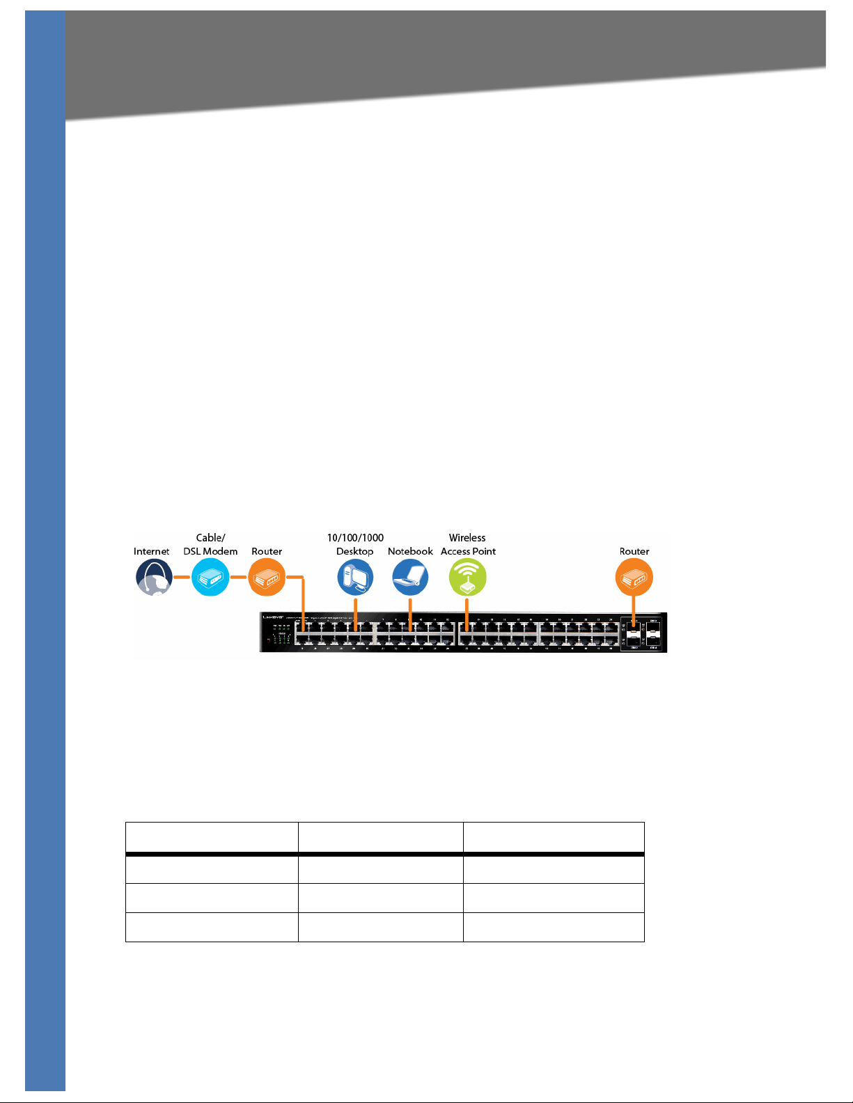
Sample Network Configuration
For an example of a possible network configuration, see the application diagrams shown
below.
Maximum Cabling Distances
When you connect your network devices, make sure you don’t exceed the maximum cabling
distances, which are listed in the following table:
From To Maximum Distance
Switch Switch or Hub* 100 meters (328 feet)
Hub Hub 5 meters (16.4 feet)
Switch or Hub Computer 100 meters (328 feet)
*A hub refers to any type of 100Mbps hub, including regular hubs and stackable hubs. A
bp
10M
SGE2010/SGE2010P Administration Guide 4
s hub connected to another 10Mbps hub can span up to 100 meters (328 feet).
Page 8

Connecting Devices to the SGE2010/SGE2010P
Before You Install the Switch...
Before You Install the Switch...
When you choose a location for the switch, observe the following guidelines:
• Make sure that the switch will be accessible and that the cables can be easily connected.
• Keep cabling away from sources of electrical noise, power lines, and fluorescent lighting
tures.
fix
• Position the switch away from water and moisture sources.
sur
• To ensure adequate air flow around the switch, be
two inches (50 mm).
e to provide a minimum clearance of
• Connect the supplied power cord to the switch’s powe
electrical outlet.
CAUTION: Ma
different power cord could damage the switch.
ke sure you use the power cord that is supplied with the switch. Use of a
r port, and plug the other end into an
Placement Options
Before connecting cables to the Ethernet switch, first you will physically install the Ethernet
switch. Either set the Ethernet switch on its four rubber feet for desktop placement, mount it in
a standard-sized, 19-inch wide for rack-mount placement, or mount it on a wall with the wallmount brackets provided.
NOTE: T
mou
Desktop Placement
1. Attach the rubber feet to the recessed areas on the bottom of the Ethernet switch.
he four supplied mounting brackets can be used for either wall mount or rack
nt installations.
2. Place the Ethernet switch on a desktop near an AC power source.
SGE2010/SGE2010P Administration Guide 5
Page 9

Connecting Devices to the SGE2010/SGE2010P
Placement Options
CAUTION: Keep enough ventilation space for the Ethernet switch so it does not exceed the
environmental restrictions mentioned in the specifications.
Rack-Mount Placement
To mount the Ethernet switch in any standard-sized, 19-inch wide, (each Ethernet switch
requires 1RU of space in the rack), follow these instructions:
1. Remove the four front screws on one side of the Ethernet switch. Retain the screws for re-
inst
allation.
2. Place one of the supplied spacers on the side of the Ethernet switch so the four holes align
he screw holes.
to t
3. Place a rack mount bracket next to the spacer and reinstall the four screws (removed in step
1).
4. Repeat steps 2 through 3 for the other side of the Ethernet switch.
5. Attach the Ethernet switch to the rack using the supplied screws.
SGE2010/SGE2010P Administration Guide 6
Page 10
Connecting Devices to the SGE2010/SGE2010P
Connecting the Cables
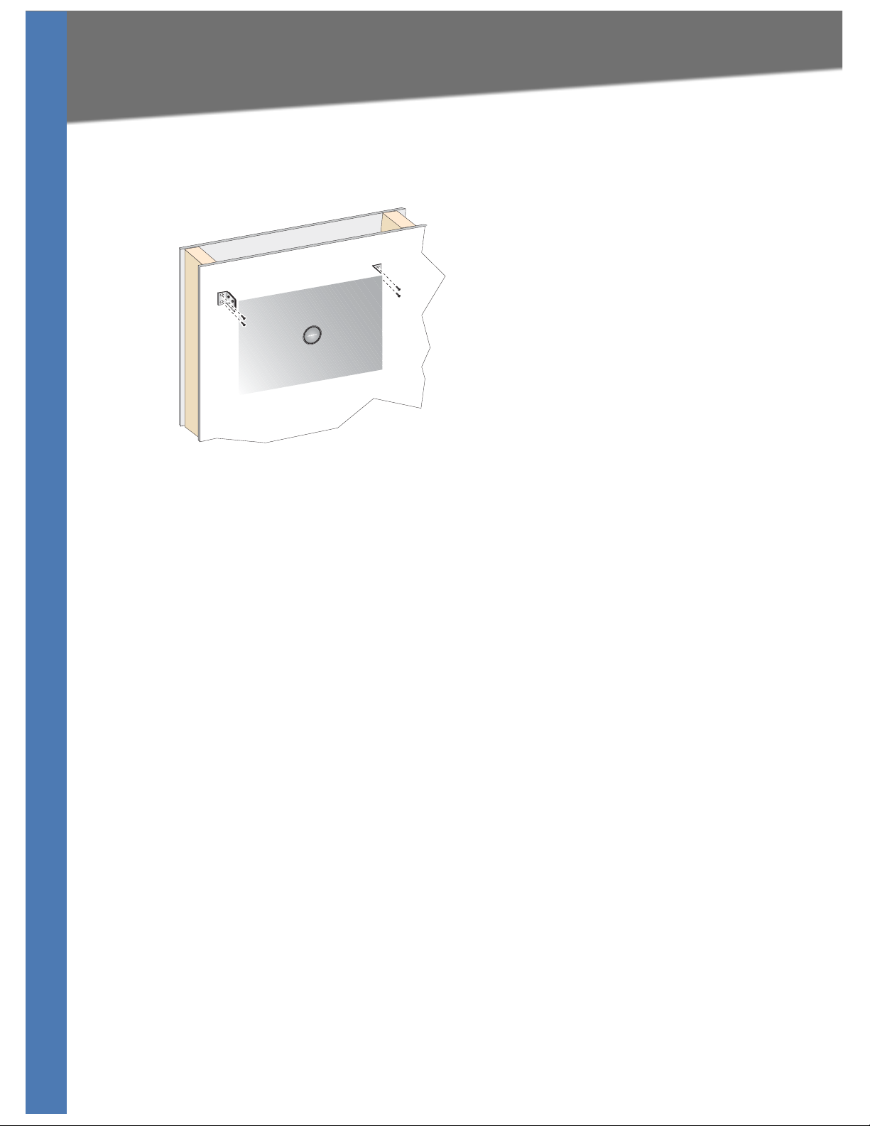
Wall-Mount Placement
1. On one of the side corners, remove the four front screws on of the Ethernet switch. Retain
the screws for re-installation.
NOTE: The Ethernet switch, shown below, is mounted with the ports located on top. When
th
e switch is mounted to a wall, the ports can be oriented in any direction.
2. Place one of the supplied spacers on the side of the Ethernet switch so the four holes align
he screw holes.
to t
3. Place a rack mount bracket next to the spacer and reinstall the four screws (removed in step
e wall mount brackets should point towards the bottom of the Ethernet switch.
1). Th
4. Repeat steps 1 through 3 for the other corners of the Ethernet switch.
5. Attach the Ethernet switch to a wall with appropriate screws (not supplied).
sur
CAUTION: En
e that the Ethernet switch is securely attached to the wall.
Connecting the Cables
To connect network devices to the Ethernet switch, follow these instructions:
1. For 10/100Mbps devices, connect a Category 5 Ethernet network cable to one of the
numbe
Ethernet network cable to one of the uplink ports on the Ethernet switch.
red ports on the Ethernet switch. For a 1000Mbps device, connect a Category 5e
NOTE: I
on the SVR3000.
2. Connect the other end to a PC or other network device.
3. Repeat steps 2 and 3 to connect additional devices.
4. If you are using the mini-GBIC port, then insert the mini-GBIC module to the mini-GBIC port.
o
F
SGE2010/SGE2010P Administration Guide 7
f connecting an Ethernet switch
r detailed instructions, refer to the documentation supplied with the mini-GBIC module.
to an SVR3000 router, connect it to a Cascade port
Page 11

Connecting Devices to the SGE2010/SGE2010P
Connecting the Cables
CAUTION: Observe the orientation of the mini-GBIC module before inserting it into a mini-
GBIC port. The bottom mini-GBIC ports are upside down in relation to the top mini-GBIC
ports.
5. If you use the console interface to configure the Ethernet switch, then connect the supplied
a
l cable to the console port (located on the back of the Ethernet switch), and tighten the
seri
captive retaining screws. Connect the other end to your PC’s serial port. (The PC must be
running VT100 terminal emulation software, such as HyperTerminal.)
6. Connect the supplied power cord to the power port, and plug the other end into an
l
ectrical outlet.
e
CAUTION: Make sure you use the power cord that is supplied with the Ethernet switch. Use
different power cord could damage the Ethernet switch.
of a
7. Power on the network devices connected to the Ethernet swi
corresponding Act/Link LED will light up on the Ethernet switch. If a port has an active
Gigabit connection, then its corresponding Gigabit LED will also light up.
8. Proceed as needed:
• If you will use the console interface to configure the Ethernet switch, proceed to
”Console Configuration” section on page 33 for directions.
• If you use the Web-based Utility to configure the Ethernet switch, proceed to ”Web
Utility Configuration” section on page 50.
tch. Each active port’s
SGE2010/SGE2010P Administration Guide 8
Page 12

Using the Console
4
Connecting to Your Switch with HyperTerminal
Using the Console
This chapter describes the use of the switch console, which allows you to perform basic
configuration of the switch.
The switch features a menu-driven console interface for basic configuration of the switch and
manageme
Configuration can also be performed through the web utility, which is covered in the next
chapter.
• ”Connecting to Your Switch with HyperTerminal,” on page 9
• ”Connecting to the Switch with Telnet,” on page 12
• Logging On to the Console (see page 12)
• Selecting Menu Options and Actions (see page 12)
nt of your network.This chapter describes console interface configuration.
• Using the Switch Main Menu (see page 13)
• System Configuration (see page 13)
• Port Status (see page 44)
• Port Configuration (see page 46)
• System Mode (Layer 2 / Layer 3) Selection (see page 48)
• Help (see page 49)
• Logout (see page 50)
Connecting to Your Switch with HyperTerminal
You can use the HyperTerminal to connect to your switch.
NOTE: The switch also can be configured through a telnet connection. Telnet to the switch IP
ress 192.168.1.254. Then, press the Enter key. The default logon ID is admin with a blank
add
password.
Before you use HyperTerminal to connect to your switch for the first time, you must configure
application on your PC. You can save the settings to use each time you connect to your
the
switch.
SGE2010/SGE2010P Administration Guide 9
Page 13
Using the Console
Connecting to Your Switch with HyperTerminal
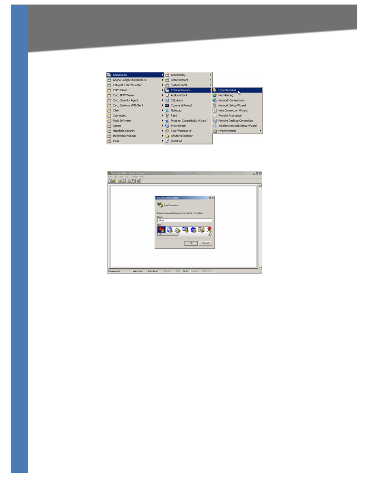
1. Click the Start button. Choose Programs > Accessories > Communications >
HyperTerminal.
2. On the Connection Description screen, type a name for this connection, select an icon, and
n click OK.
the
3. On the Connect T
communicate with the switch: COMn, or TCP/ IP.
o screen, use the Connect using drop-down list to select a port to
SGE2010/SGE2010P Administration Guide 10
Page 14
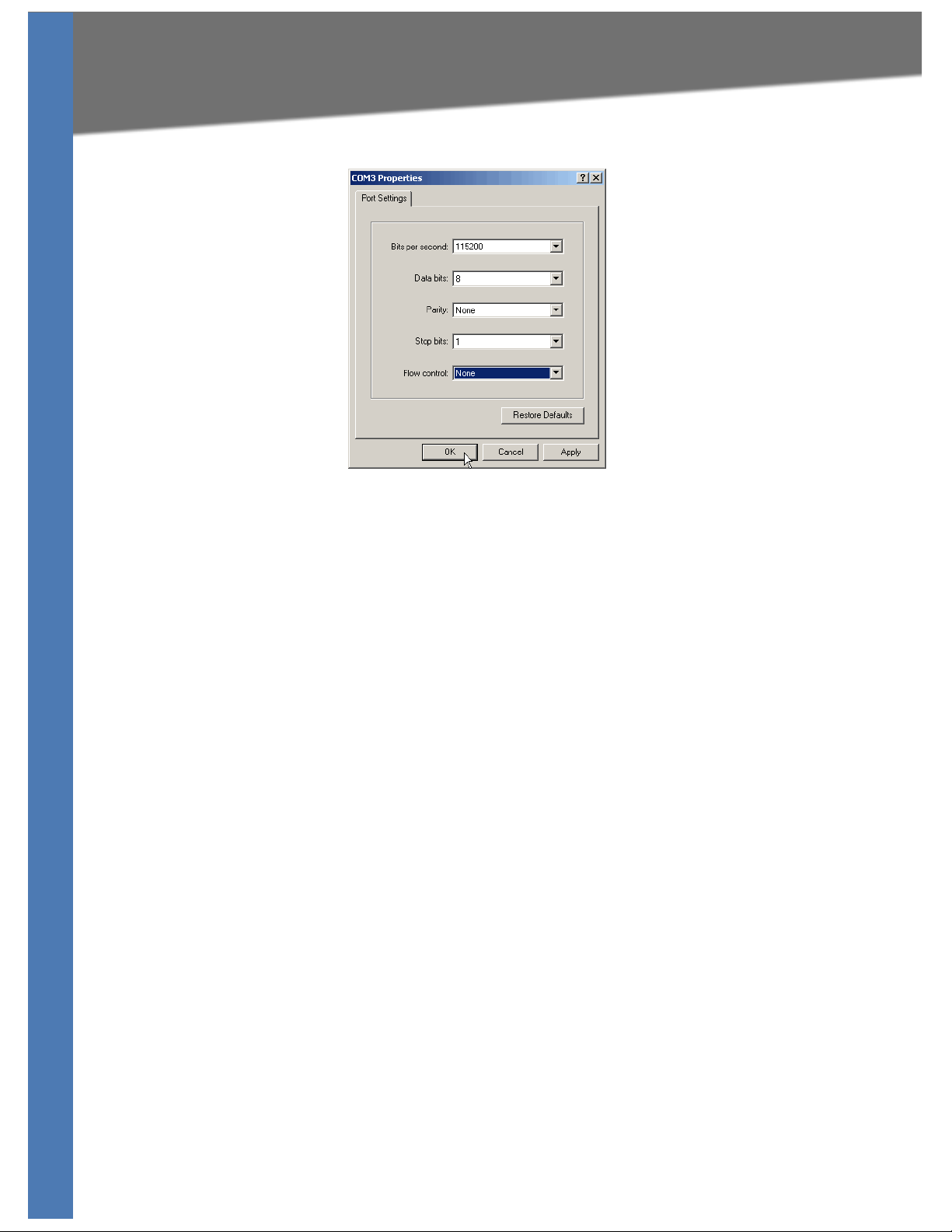
4. Set the serial port settings as follows:
Using the Console
Connecting to Your Switch with HyperTerminal
• Bits per second: 115200
• Data bits: 8
• Parity: No
• Stop bits: 1
• Flow control: None
Then, click the OK button.
5.
ne
Optionally, on the File menu, click Save to save these settings. The next time that you need
6.
to connect to the console, you can open this saved connection.
SGE2010/SGE2010P Administration Guide 11
Page 15

Connecting to the Switch with Telnet
Connecting to the Switch with Telnet
You can connect to the switch with telnet.
Using the Console
1. Open a command line editor and enter telnet <
key.
2. When the Log
the Password field blank.
3. Press the Esc
4. Select Ent
NOTE: The Use
users.
in screen appears, select Edit and enter admin in the User Name field. Leave
key to return to the Login screen.
er to enter the CLI interface.
rname & Password Settings screen can also be used to set passwords for other
switch ip address>. Then, press the Enter
Logging On to the Console
1. Start HyperTerminal and open the connection that you configured previously.
2. When the blinking cursor appears, press the Ent
3. When prompted to login, enter the default login and password: admi
The Switch Main Menu a
ppears.
er key.
n
Selecting Menu Options and Actions
Within the Console Interface, menus list options in numeric order. Actions appear at the end of
the screen. To select menu options and actions, use the following keys on your keyboard:
Key Function
Arrow keys Move the cursor up, down, left, or right.
Number key Press the menu number and then press Enter key to select a menu
option.
Tab Move the cursor from one field to the next on an editing screen.
Enter Select an option that is highlighted by the cursor.
Esc Return to the previous menu or screen, or move cursor from
editable fields to Action list.
SGE2010/SGE2010P Administration Guide 12
Page 16

Using the Console
Using the Switch Main Menu
Using the Switch Main Menu
The Switch Main Menu provides access to screens that you can use to configure your system,
view or modify port and PoE settings, and view or modify system and stacking mode.
1. System Configuration (see page 13)
2. Port Status (see page 44)
3. Port Configuration (see page 46)
4. System Mode (Layer 2 / Layer 3) Selection (see page 48)
5. Help (see page 49)
ogout (see page 50)
0.L
System Configuration
The System Configuration Menu provides access to screens where you can manage system
information, view or modify management settings, set up user accounts, and manage security
settings. It also provides access to screens where you can manage VLAN IDs, IPv4 and IPv6
settings, and download upgrade files. You also will use this menu if you need to restore default
settings, reset the switch to the factory default configuration, or reboot the system.
1. System Information (see page 14)
2. Management Settings (see page 16)
SGE2010/SGE2010P Administration Guide 13
Page 17

3. Username & Password Settings (see page 21)
4. Security Settings (see page 22)
5. VLAN Management (see page 25)
6. IP Configuration (see page 26)
7. File Management (see page 40)
8. Restore System Default Settings (see page 43)
9. Reset to Factory Settings (see page 43)
10. Reboot System (see page 43)
11. Stack Configuration (see page 44)
0.Back (Select return to the previous menu.)
Using the Console
System Configuration
To open this screen:
From the S
witch Main Menu, s
elect 1. System Configuration Menu.
System Information
The System Information menu provides access to screens where you can view firmware version
information and general system information.
1. Versions (see page 15)
2. General Information (see page 15)
0.Back (Select to return to the previous menu.)
To op e n th is me nu:
w
1. From the S
2. From the Sy
3. When you are finished using this screen, select 0. Ba
SGE2010/SGE2010P Administration Guide 14
itch Main Menu, select 1. System Configuration.
stem Configuration Menu, select 1. System Information.
ck.
Page 18

Using the Console
System Configuration
Versions
Use the Versions screen to display the boot, software, and hardware firmware versions of the
Ethernet switch. In stacking mode, this information is displayed for the stack master.
To open this screen:
1. From the Sw
2. From the Sy
3. From the Sys
itch Main Menu, select 1. System Configuration.
stem Configuration Menu, select 1. System Information.
tem Information Menu, select 1. Versions.
General Information
Use the General System Information screen to view the system description, system up time, and
system MAC address. You also can enter a system contact, system name, and system location.
To open this screen:
w
1. From the S
2. From the Sy
3. From the Sys
SGE2010/SGE2010P Administration Guide 15
itch Main Menu, select 1. System Configuration.
stem Configuration Menu, select 1. System Information.
tem Information Menu, select 2. General System Information.
Page 19

Using the Console
System Configuration
To change the system contact, system name, and location:
1. Select Edit, and then make your changes. Press the Tab key to move the cursor from one
field to the next.
2. Press the Esc ke
3. Select Sav
4. When the Oper
Action list.
y to return to the Action list.
e to save your changes.
ation complete message appears, press the Esc key to move the cursor to the
Management Settings
The Management Settings screen provides access to screens where you can change the settings
for serial port, telnet, and secure telnet (SSH).
1. Serial Port Configuration (see page 17)
2. Telnet Configuration (see page 17)
3. SSH Configuration (see page 18)
0.Back (Select to return to the previous menu.)
To open this screen:
w
1. From the S
2. From the Sy
itch Main Menu, select 1. System Configuration Menu.
stem Configuration Menu, select 2. Management Settings.
SGE2010/SGE2010P Administration Guide 16
Page 20

Using the Console
System Configuration
Serial Port Configuration
Use the Serial Port Configuration screen to view or change the baud rate of the Ethernet switch.
To open this screen:
w
1. From the S
2. From the Sy
3. From the Ma
To change the baud rate of the serial port:
1. Select Ed
2. Press the Esc ke
3. Select Sav
4. When the Oper
Action list.
itch Main Menu, select 1. System Configuration Menu.
stem Configuration Menu, select 2. Management Settings.
nagement Settings Menu, choose 1. Serial Port Configuration.
i
t, and then make changes.
y to move the cursor to the Action list.
e to save your changes.
ation complete message appears, press the Esc key to move the cursor to the
Tel net Con fig urati on
Use the Telnet Configuration screen to view or change the time-out settings.
SGE2010/SGE2010P Administration Guide 17
Page 21

Using the Console
To open this screen:
1. From the Switch Main Menu, select 1. System Configuration Menu.
System Configuration
2. From the Sy
3. From the Ma
To change the time-out setting:
1. Select Ed
2. Press the Esc ke
3. Select Sav
4. When the Oper
Action list.
stem Configuration Menu, select 2. Management Settings.
nagement Settings Menu, choose 2. Telnet Configuration.
i
t, and then make your changes.
y to move the cursor to the Action list.
e to save your changes.
ation complete message appears, press the Esc key to move the cursor to the
SSH Configuration
The SSH Configuration menu provides access to screens where you can configure SSH server
settings, generate crypto keys, and generate keys fingerprints.
1. SSH Server Configuration (see page 19)
2. SSH Status (see page 19)
3. SSH Crypto Key Generation (see page 20)
4. SSH Keys Fingerprints (see page 21)
0.Back (Select to return to the previous menu.)
To open this screen:
itch Main Menu, select 1. System Configuration Menu.
1. From the S
2. From the Sy
3. From the Ma
SGE2010/SGE2010P Administration Guide 18
w
stem Configuration Menu, select 2. Management Settings.
nagement Settings Menu, choose 3. SSH Configuration.
Page 22

SSH Server Configuration
Using the Console
System Configuration
Use the SSH Server Configuration scr
enable or disable the server and configure the SSH server port
To open this screen:
w
1. From the S
2. From the Sy
3. From the Ma
4. From the SSH C
itch Main Menu, select 1. System Configuration Menu.
stem Configuration Menu, select 2. Management Settings.
nagement Settings Menu, choose 3. SSH Configuration.
onfiguration Menu, select 1. SSH Server Configuration.
een to view or edit the status of the SSH server. You can
To change SSH Server settings:
i
1. Select Ed
2. Press the Esc ke
3. Select Sav
4. When the Oper
Action list.
SSH Status
Use the SSH Status screen to view information about SSH sessions.
t, and then make your changes.
y to move the cursor to the Action list.
e to save your changes.
ation complete message appears, press the Esc key to move the cursor to the
SGE2010/SGE2010P Administration Guide 19
Page 23

Using the Console
To open this screen:
1. From the Switch Main Menu, select 1. System Configuration Menu.
System Configuration
2. From the Sy
3. From the Ma
4. From the SSH C
5. When you finish using this screen, select Quit.
SH Crypto Key Generation
S
Use the SSH Crypto Key Generation screen to generate an SSH RSA or DSA key.
stem Configuration Menu, select 2. Management Settings.
nagement Settings Menu, choose 3. SSH Configuration.
onfiguration Menu, select 2. SSH Status.
To open this screen:
w
1. From the S
2. From the Sy
3. From the Ma
4. From the SSH C
5. When you finish using this screen, select Quit.
o change SSH Crypto Key Generation settings:
T
NOTE: Only t
1. Select Edi
2. Press the Esc ke
3. Select Sav
4. When the Oper
Action list.
itch Main Menu, select 1. System Configuration Menu.
stem Configuration Menu, select 2. Management Settings.
nagement Settings Menu, choose 3. SSH Configuration.
onfiguration Menu, select 3. SSH Crypto Key Generation.
he public key algorithm can be changed.
t, and then make your changes.
y to move the cursor to the Action list.
e to save your changes.
ation complete message appears, press the Esc key to move the cursor to the
SGE2010/SGE2010P Administration Guide 20
Page 24

To generate the crypto key:
1. Verify that the information is correct.
Using the Console
System Configuration
2. Select Exec
3. When the Oper
Action list.
SSH Keys Fingerprints
Use the SSH
To open this screen:
1. From the Sw
ute.
ation complete message appears, press the Esc key to move the cursor to the
Keys Fingerprints scre
itch Main Menu, select 1. System Configuration Menu.
en to view the RSA and DSA fingerprints.
2. From the Sy
3. From the Ma
4. From the SSH C
5. When you finish using this screen, select Quit.
stem Configuration Menu, select 2. Management Settings.
nagement Settings Menu, choose 3. SSH Configuration.
onfiguration Menu, select 4. SSH Keys Fingerprints.
Username & Password Settings
You can use the Username & Password Settings screen to view, add, or modify the user accounts
for the switch. Up to five users can be assigned.
SGE2010/SGE2010P Administration Guide 21
Page 25

NOTE: The default user is “admin” with no password.
To open this screen:
1. From the Switch Main Menu, select 1. System Configuration.
Using the Console
System Configuration
2. From the Sy
To change User & Password settings:
1. Select Ed
next.
NOTE: The username and password can be 20 characters in length. You must enter the
e password in the Password field and the Password Again field.
sam
2. Press the Esc ke
3. Select Sav
4. When the Oper
Action list.
stem Configuration Menu, select 3. Username & Password Settings.
i
t, and then make your changes. Press the Tab key to move from one field to the
y to move the cursor to the Action list.
e to save your changes.
ation complete message appears, press the Esc key to move the cursor to the
Security Settings
The Security Settings screen provides access to screens where you can generate SSL certificates
and view the SSL certificate listings. You also can use this module to disable the active
management access profile.
1. SSL Generate Certificate (see page 23)
2. Show Certificate (see page 24)
3. Disable Active Management Access Profile (see page 24)
0.Back (Select to return to the previous menu.)
To open this screen:
itch Main Menu, select 1. System Configuration.
1. From the S
2. From the Sy
SGE2010/SGE2010P Administration Guide 22
w
stem Configuration Menu, select 4. Security Settings.
Page 26

Using the Console
System Configuration
SSL Generate Certificate
Use the SSL Certificate Generation screen to view, edit, and execute device-generated
certificates.
To open this screen:
w
1. From the S
2. From the Sy
3. From the Sec
itch Main Menu, select 1. System Configuration.
stem Configuration menu, select 4. Security Settings.
urity Settings Menu, select 1. SSL Generate Certificate.
To edit and execute a certificate:
i
1. Select Ed
t, and then make your changes. Press the Tab key to move the cursor from field to
field.
2. Press the Esc ke
3. Select Exec
4. When the Oper
y to move the cursor to the Action list.
ute to generate the certificate with the new parameters.
ation complete message appears, press the Esc key to move the cursor to the
Action list.
The following fields are specified:
Public Key Algorithm Specifies the SSL type
Public Key Length Specifies the SSL RSA key length. (Range: 512 to 2048)
Common Name (FQCN) IP address of the Ethernet switch
Department Name Specifies the department name. (Range: 1 to 32 characters)
Organization Name Specifies the organization name. (Range: 1 to 32
characters)
Locality or City Name Specifies the location or city name. (Range: 1 to 32
characters)
State or Province Name Specifies the state or province name. (Range: 1 to 32
characters)
SGE2010/SGE2010P Administration Guide 23
Page 27

Using the Console
System Configuration
Country Name Specifies the country name. (Range: 2 to 2)
Validity Term Specifies number of days certification is valid. (Range: 30 to
3650)
Show Certificate
Use the Show Certificate screen to display the internal certificate.
To open this screen:
1. From the Sw
2. From the Sy
3. From the Sec
itch Main Menu, select 1. System Configuration.
stem Configuration Menu, select 4. Security Settings.
urity Settings Menu, select 2. SSL Show Certificate.
4. When you finish using this screen, select Quit.
Disable Active Management Access Profile
You can use select option 3 on the Security Settings menu to disable the active management
access profile.
To disable the active management access profile:
w
1. From the S
2. From the Sy
3. From the Sec
4. When the confirmation message appears, press Y to
itch Main Menu, select 1. System Configuration.
stem Configuration menu, select 4. Security Settings.
urity Settings Menu, select 3. Disable Active Management Access Profile.
confirm, or press N to cancel.
SGE2010/SGE2010P Administration Guide 24
Page 28

Using the Console
System Configuration
VLAN Management
The VLAN Management menu provides access to a screen where you can view or modify the
default VLAN ID.
1. Default VLAN Setup (see page 25)
0.Back (Select to return to the previous menu.)
To open this screen:
itch Main Menu, select 1. System Configuration.
1. From the S
2. From the Sy
w
stem Configuration Menu, select 5. Vlan Management.
Default VLAN Setup
You can use the Default VLAN Setup screen to view and change the VLAN ID.
To open this screen:
1. From the Sw
2. From the Sy
3. From the VLAN
SGE2010/SGE2010P Administration Guide 25
itch Main Menu, select 1. System Configuration.
stem Configuration Menu, select 5. Vlan Management.
Management menu, press 1. Default VLAN Setup.
Page 29

To ed it t he V LA N ID :
1. Select Edit.
2. Type the VLAN ID.
Using the Console
System Configuration
3. Press the Esc ke
4. Select Exec
5. When the Oper
Action list.
y to move the cursor to the Action list.
ute.
ation complete message appears, press the Esc key to move the cursor to the
IP Configuration
The IP Configuration menu provides access to screens where you can manage IPv4 and IPv6
address configuration, HTTP and HTTPS configuration, and network configuration.
1. IPv4 Address Configuration (see page 27)
2. IPv6 Address Configuration (see page 28)
3. HTTP Configuration (see page 34)
4. HTTPS Configuration (see page 34)
5. Network Configuration (see page 35)
0.Back (Select to return to the previous menu.)
To open this screen:
w
1. From the S
2. From the Sy
itch Main Menu, select 1. System Configuration.
stem Configuration Menu, select 6. IP Configuration.
SGE2010/SGE2010P Administration Guide 26
Page 30

Using the Console
System Configuration
IPv4 Address Configuration
The IPv4 Configuration menu provides access to the IPv4 address settings and DHCP renew.
1. IPv4 Address Settings (see page 27)
2. DHCP Renew (see page 28)
0.Back (Select to return to the previous menu.)
To open this screen:
itch Main Menu, select 1. System Configuration.
1. From the S
2. From the Sy
3. From the IP
IPv4 Address Settings
You can use this screen to view or editing the IPv4 address settings.
w
stem Configuration Menu, select 6. IP Configuration.
Configuration menu, select 1. IPv4 Address Configuration.
To open this screen:
w
1. From the S
2. From the Sy
3. From the IP
SGE2010/SGE2010P Administration Guide 27
itch Main Menu, select 1. System Configuration.
stem Configuration Menu, select 6. IP Configuration.
Configuration menu, select 1. IPv4 Address Configuration.
Page 31

Using the Console
System Configuration
4. From the IPv4 Address Configuration menu, select 1. IPv4 Address Settings.
To edit the IPv4 address settings:
i
1. Select Ed
field to the next.
NOTE: To enable or disable the DHCP client, move the cursor to the field, and then press the
ace Bar to toggle between ENABLE and DISABLE.
Sp
t., and then make the changes. Press the Ta b key to move the cursor from one
2. Press the Esc ke
3. Select Sav
4. When the Oper
Action list.
DHCP Renew
You can select this option to renew DHCP.
NOTE: T
IP
To re new DH CP:
1. From the S
2. From the Sy
3. From the IP
4. From the IP
his option is available only if the interface is configured as a DHCP interface, through
v4 Address Settings.
message appears.
y to move the cursor to the Action list.
e to save your settings
ation complete message appears, press the Esc key to move the cursor to the
w
itch Main Menu, select 1. System Configuration.
stem Configuration Menu, select 6. IP Configuration.
Configuration menu, select 1. IPv4 Address Configuration.
v4 Address Configuration menu, select 2. DHCP Renew. The Operation Complete
IPv6 Address Configuration
The IPv6 Configuration menu provides access to screens where you can manage the settings for
IPv6 and ISATAP.
SGE2010/SGE2010P Administration Guide 28
Page 32

1. IPv6 Interface Enable (see page 29)
2. IPv6 Address Settings (see page 30)
3. IPv6 Address Table (see page 31)
4. IPv6 ISATAP Enable (see page 31)
5. IPv6 ISATAP Interface Show (see page 32)
6. IPv6 Default Gateway (see page 33)
To open this screen:
w
1. From the S
itch Main Menu, select 1. System Configuration.
Using the Console
System Configuration
2. From the Sy
3. From the IP
IPv6 Interface Enable
You can use the IPv6 Int
To open this screen:
1. On the Sw
stem Configuration Menu, select 6. IP Configuration.
Configuration menu, select 2. IPv6 Address Configuration.
itch Main Menu, select 6. IP Configuration.
erface Enable screen to enable or disable the IPv6 interface.
2. On the IP Configuration menu, selec
3. On the IPv6 Address Configuration me
To edit the IPv6 interface settings:
1. When you finish using this Select Ed
move the cursor from one field to the next.
NOTE: To enable or disable the interface, move the cursor to the field, and then press the
ace Bar to toggle between ENABLE and DISABLE. If you select ENABLE, a warning
Sp
appears. Press the Enter key to acknowledge the warning.
c ke
2. Press the Es
SGE2010/SGE2010P Administration Guide 29
y to move the cursor to the Action list.
t 2. IPv6 Address Configuration.
nu, select 1. IPv6 Interface Enable.
i
t., and then make the changes. Press the Tab key to
Page 33

3. Select Save to save your settings
Using the Console
System Configuration
4. When the Oper
Action list.
5. When you are finished working on this screen, select Qui
IPv6 Address Settings
You can use the IP
To open this screen:
1. From the Sw
ation complete message appears, press the Esc key to move the cursor to the
v6 Address - Configuration screen to edit the IPv6 address settings.
itch Main Menu, select 1. System Configuration.
t.
2. From the Sy
3. From the IP
4. From the IP
To edit the IPv6 address settings:
1. Select Ed
field to the next.
NOTE: To enable or disable the DHCP client, move the cursor to the field, and then press the
ace Bar to toggle between ENABLE and DISABLE.
Sp
2. Press the Esc ke
3. Select Sav
4. When the Oper
Action list.
stem Configuration Menu, select 6. IP Configuration.
Configuration menu, select 2. IPv6 Address Configuration.
v6 Address Configuration menu, select 2. IPv6 Address Settings.
i
t., and then make the changes. Press the Ta b key to move the cursor from one
y to move the cursor to the Action list.
e to save your settings
ation complete message appears, press the Esc key to move the cursor to the
SGE2010/SGE2010P Administration Guide 30
Page 34

IPv6 Address Table
The IPv6 Address Table lists the IPv6 addresses that are configured.
To open this screen:
Using the Console
System Configuration
w
1. From the S
2. From the Sy
3. From the IP
4. From the IP
IPv6 ISATAP Enable
You can use the IPv6 I
itch Main Menu, select 1. System Configuration.
stem Configuration Menu, select 6. IP Configuration.
Configuration menu, select 2. IPv6 Address Configuration.
v6 Address Configuration menu, select 3. IPv6 Address Table.
SATAP Enable screen to configure the ISATAP tunnel.
To open this screen:
1. From the Sw
2. From the Sy
3. From the IP
4. From the IP
SGE2010/SGE2010P Administration Guide 31
itch Main Menu, select 1. System Configuration.
stem Configuration Menu, select 6. IP Configuration.
Configuration menu, select 2. IPv6 Address Configuration.
v6 Address Configuration menu, select 4. IPv6 ISATAP Enable.
Page 35

Using the Console
System Configuration
To edit the ISATAP tunnel settings
1. Select Edit., and then make the changes. Press the Tab key to move the cursor from one
field to the next.
NOTE: To enable or disable the ISATAP tunnel, move the cursor to the Sta
press the Space Bar to toggle between ENABLE and DISABLE.
2. Press the Esc ke
3. Select Sav
4. When the Oper
Action list.
IPv6 ISATAP Interface Show
You can use the
y to move the cursor to the Action list.
e to save your settings
ation complete message appears, press the Esc key to move the cursor to the
ISATAP Interface Show screen to view the interface type and address.
tus field, and then
To open this screen:
1. From the Sw
2. From the Sy
3. From the IP
4. From the IP
SGE2010/SGE2010P Administration Guide 32
itch Main Menu, select 1. System Configuration.
stem Configuration Menu, select 6. IP Configuration.
Configuration menu, select 2. IPv6 Address Configuration.
v6 Address Configuration menu, select 5. ISATAP Interface Show.
Page 36

IPv6 Default Gateway
Using the Console
System Configuration
You can use the IPv
Gateway.
To open this screen:
w
1. From the S
2. From the Sy
3. From the IP
4. From the IP
itch Main Menu, select 1. System Configuration.
stem Configuration Menu, select 6. IP Configuration.
Configuration menu, select 2. IPv6 Address Configuration.
v6 Address Configuration menu, select 6. IPv6 Default Gateway.
6 Default Gateway screen to view or edit information about the IPv6 Default
To edit the IPv6 default gateway settings:
i
1. Select Ed
field to the next.
NOTE: To change the state of the gateway, move the cursor to the St
the Space Bar to toggle between ENABLE and DISABLE.
2. Press the Esc ke
3. Select Exec
4. When the Oper
Action list.
t., and then make the changes. Press the Ta b key to move the cursor from one
y to move the cursor to the Action list.
ute to save your settings
ation complete message appears, press the Esc key to move the cursor to the
ate field, and then press
SGE2010/SGE2010P Administration Guide 33
Page 37

Using the Console
System Configuration
HTTP Configuration
You can use the HTTP screen to view and edit the HTTP settings.You can enable or disable the
HTTP server and configure the port on which the session is enabled.
To open the screen:
1. From the Sw
2. From the Sy
3. From the IP
To change the HTTP settings:
1. Select Ed
2. Press the Esc ke
3. Select Sav
4. When the Oper
Action list.
itch Main Menu, select 1. System Configuration.
stem Configuration Menu, select 6. IP Configuration.
Configuration menu, select 3. HTTP Configuration.
i
t, and then make your changes.
y to move the cursor to the Action list.
e to save your changes.
ation complete message appears, press the Esc key to move the cursor to the
HTTPS Configuration
Use the HTTPS Configuration screen to configure HTTPS settings. You can enable or disable the
HTTPS server and configure the port on which the session is enabled.
SGE2010/SGE2010P Administration Guide 34
Page 38

To open the screen:
1. From the Switch Main Menu, select 1. System Configuration.
Using the Console
System Configuration
2. From the Sy
3. From the IP
To ch a ng e HT TPS s ett i ngs :
1. Select Ed
2. Press the Esc ke
3. Select Sav
4. When the Oper
Action list.
stem Configuration Menu, select 6. IP Configuration.
Configuration menu, select 4. HTTPS Configuration.
i
t, and then make your changes.
y to move the cursor to the Action list.
e to save your changes.
ation complete message appears, press the Esc key to move the cursor to the
Network Configuration
The Network Configuration screen provides access to screens where you can execute ping tests
and traceroute tests for IPv4 and IPv6 addresses.
1. Ping IPv4 (see page 36)
2. Ping IPv6 (see page 37)
3. TraceRoute IPv4 (see page 38)
4. TraceRoute IPv6 (see page 39)
0.Back (Select to return to the previous menu.)
To open the screen:
itch Main Menu, select 1. System Configuration.
1. From the S
2. From the Sy
3. From the IP
SGE2010/SGE2010P Administration Guide 35
w
stem Configuration Menu, select 6. IP Configuration.
Configuration menu, select 5. Network Configuration.
Page 39

Ping IPv4
Using the Console
System Configuration
You can use the Ping IPv
To open the screen:
1. From the Sw
2. From the Sy
3. From the IP
4. From the Network C
itch Main Menu, select 1. System Configuration.
stem Configuration Menu, select 6. IP Configuration.
Configuration menu, select 5. Network Configuration.
4 screen to ping an IPv4 address.
onfiguration menu, select 1. IPv4 Ping.
To change the IP address:
i
1. Select Ed
2. Press the Esc ke
3. Select Sav
4. When the Oper
Action list.
To be gin the ping test :
1. Select Ex
2. After the ping test is complete, the results of the test appear on the screen.
3. When the Oper
Action list.
t, and then enter the IP address.
y to move the cursor to the Action list.
e to save your changes.
ation complete message appears, press the Esc key to move the cursor to the
ec
ute to begin the ping test.
ation complete message appears, press the Esc key to move the cursor to the
SGE2010/SGE2010P Administration Guide 36
Page 40

Ping IPv6
Using the Console
System Configuration
You can use the Ping IPv
To open the screen:
1. From the Sw
2. From the Sy
3. From the IP
4. From the Network C
itch Main Menu, select 1. System Configuration.
stem Configuration Menu, select 6. IP Configuration.
Configuration menu, select 5. Network Configuration.
6 screen to ping an IPv6 address.
onfiguration menu, select 2. IPv6 Ping.
To change the IP address:
i
1. Select Ed
2. Press the Esc ke
3. Select Sav
4. When the Oper
Action list.
To be gin the ping test :
1. Select Ex
2. After the ping test is complete, the results of the test appear on the screen.
3. When the Oper
Action list.
t, and then enter the IPv6 address.
y to move the cursor to the Action list.
e to save your changes.
ation complete message appears, press the Esc key to move the cursor to the
ec
ute to begin the ping test.
ation complete message appears, press the Esc key to move the cursor to the
SGE2010/SGE2010P Administration Guide 37
Page 41

TraceRoute IPv4
Using the Console
System Configuration
You can use the Tra
To open the screen:
1. From the Sw
2. From the Sy
3. From the IP
4. From the Network C
ceRoute IP v4 screen to run a trace route test for an IPv4 address
itch Main Menu, select 1. System Configuration.
stem Configuration Menu, select 6. IP Configuration.
Configuration menu, select 5. Network Configuration.
onfiguration menu, select 3. Trace Router IPv4.
To change the IP address:
i
1. Select Ed
2. Press the Esc ke
To begin the trace route test:
1. Select Ex
2. After the test is complete, the results of the test appear on the screen.
3. When the Oper
Action list.
t, and then enter the IPv4 address.
y to move the cursor to the Action list.
ec
ute to begin the test.
ation complete message appears, press the Esc key to move the cursor to the
SGE2010/SGE2010P Administration Guide 38
Page 42

TraceRoute IPv6
Using the Console
System Configuration
You can use the Tra
To open the screen:
1. From the Sw
2. From the Sy
3. From the IP
4. From the Network C
ceRoute IP v6 screen to run a trace route test for an IPv6 address.
itch Main Menu, select 1. System Configuration.
stem Configuration Menu, select 6. IP Configuration.
Configuration menu, select 5. Network Configuration.
onfiguration menu, select 4. Trace Router IPv6.
To change the IP address:
i
1. Select Ed
2. Press the Esc ke
To begin the trace route test:
1. Select Ex
2. After the test is complete, the results of the test appear on the screen.
3. When the Oper
Action list.
t, and then enter the IPv6 address.
y to move the cursor to the Action list.
ec
ute to begin the test.
ation complete message appears, press the Esc key to move the cursor to the
SGE2010/SGE2010P Administration Guide 39
Page 43

Using the Console
System Configuration
File Management
The File Management Menu provides access to screens where you can download upgrade files
from an IPv4 or IPv6 address.
1. Upgrade / Backup IPv4 (see page 40)
2. Upgrade / Backup IPv6 (see page 41)
3. Active Image (see page 42)
0.Back (Select to return to the previous menu.)
To open this screen:
w
1. From the S
2. From the Sy
itch Main Menu, select 1. System Configuration.
stem Configuration Menu, select 7. File Management.
Upgrade / Backup IPv4
You can use the Upgrade/Backup IPv4 screen to download files from an IPv4 address.
To open this screen:
w
1. From the S
2. From the Sy
3. From the File M
SGE2010/SGE2010P Administration Guide 40
itch Main Menu, select 1. System Configuration.
stem Configuration Menu, select 7. File Management.
anagement Menu, select 1. IPv4 Upgrade/Backup.
Page 44

Using the Console
System Configuration
To enter the IPv4 Upgrade/Backup file name and location:
1. Select Edit, and then make the changes. Press the Ta b key to move the cursor from one
field to the next.
NOTE: Specify the source and destination of the file, the file name, and the IPv4 address of
he file server where the upgrade file is stored,
t
2. Press the Esc ke
To download a file from the specified location:
3. Verify that the file name and location are correct.
4. Select Ex
5. When the Oper
Action list.
ec
y to move the cursor to the Action list.
ute.
ation complete message appears, press the Esc key to move the cursor to the
Upgrade / Backup IPv6
You can use the Upgrade/Backup IPv6 screen to download files from an IPv6 address.
To open this screen:
w
1. From the S
2. From the Sy
3. From the File M
To enter the IPv6 Upgrade/Backup file
1. Select Edi
field to the next.
NOTE: Specify the source and destination of the file, the file name, and the IPv6 address of
he file server where the upgrade file is stored. For an IPv6 address, you also must specify
t
the interface type and ID.
2. Press the Es
SGE2010/SGE2010P Administration Guide 41
itch Main Menu, select 1. System Configuration.
stem Configuration Menu, select 7. File Management.
anagement Menu, select 2. IPv6 Upgrade/Backup.
name and location:
t, and then make the changes. Press the Tab key to move the cursor from one
c ke
y to move the cursor to the Action list.
Page 45

To download a file from the specified location:
3. Verify that the file name and location are correct.
Using the Console
System Configuration
4. Select Exec
5. When the Oper
Action list.
ute.
ation complete message appears, press the Esc key to move the cursor to the
Active Image
There are two software images on the Ethernet switch: Image 1 and Image 2. When you copy an
image to the switch via TFTP, the inactive image is replaced. When you copy an image to the
switch via the console port, the active image is replaced.You can use the Active Image screen to
specify which image is the active image on the switch.
To open this screen:
w
1. From the S
2. From the Sy
3. From the File M
To enter the active image settings
1. Select Ed
2. Press the Spac
3. When the correct image setting appears in the field, press the Esc key
the Action list.
4. Select Exec
5. When the Oper
Action list.
itch Main Menu, select 1. System Configuration.
stem Configuration Menu, select 7. File Management.
anagement Menu, select 3. Active Image.
i
t. The cursor moves to the Active Image after Reset field.
e Bar to change the image setting.
ute to save your settings. The selected image will be active after reset.
ation complete message appears, press the Esc key to move the cursor to the
to move the cursor to
SGE2010/SGE2010P Administration Guide 42
Page 46

Restore System Default Settings
You can restore the switch to the system default settings.
To restore system default settings
w
1. From the S
itch Main Menu, select 1. System Configuration.
Using the Console
System Configuration
2. From the Sy
3. When the confirmation message appears, press y to r
to cancel.
NOTE: Restoring default settings from the console or web resets all values except stacking
onfiguration (stacking mode, stacking ports, and auto-numbering settings are not reset). To
c
reset stacking configuration, use the hardware reset button on the front of the Ethernet switch.
stem Configuration Menu, select 8. Restore System Default Settings.
estore the default settings, or press n
Reset to Factory Settings
You can restore the switch to the factory default settings.
To restore factory default settings
w
1. From the S
2. From the Sy
3. When the confirmation message appears, press y to r
to cancel.
NOTE: Restoring factory settings from the console or web resets all values except stacking
onfiguration (stacking mode, stacking ports, and auto-numbering settings are not reset). To
c
reset stacking configuration, use the hardware reset button on the front of the Ethernet switch.
itch Main Menu, select 1. System Configuration.
stem Configuration Menu, select 9. Restore Factory Settings.
estore the default settings, or press n
Reboot System
You can restart the Ethernet switch.
To restore system default settings
w
1. From the S
2. From the Sy
3. When the confirmation message appears, press y to r
to cancel.
SGE2010/SGE2010P Administration Guide 43
itch Main Menu, select 1. System Configuration.
stem Configuration Menu, select 10. Reboot System.
estore the default settings, or press n
Page 47

Using the Console
Port Status
Stack Configuration
You can use the Stack Configuration screen to specify the Stack ID for the Ethernet switch. By
default, ID numbers are automatically assigned to each device.
To open this screen:
w
1. From the S
2. From the Sy
itch Main Menu, select 1. System Configuration.
stem Configuration Menu, select 11. Stack Configuration.
Port Status
The Port Status menu provides access to screens where you can view the port status and the
PoE status for each port on the switch.
1. Port Status (see page 45)
2. PoE Status (see page 45)
0.Back (Select to return to the previous screen.)
To open this screen:
From the S
SGE2010/SGE2010P Administration Guide 44
witch Main Menu, pr
ess 2. Port Status.
Page 48

Using the Console
Port Status
Port Status
You can use the Port Status screen to view the port connection status. You can use the up or
down arrow keys to scroll through all the ports on the switch.
NOTE: To configure ports, use the P
To open this screen:
w
1. From the S
2. From the Por
itch Main Menu, press 2. Port Status.
t Status Menu, press 1. Port Status.
ort Configuration screen. See ”Port Settings,” on page 46.
PoE Status
You can use the PoE Status screen to view the PoE status of the ports.
NOTE: To configure PoE, use the P
To open this screen:
w
1. From the S
2. From the Por
SGE2010/SGE2010P Administration Guide 45
itch Main Menu, press 2. Port Status.
t Status Menu, press 2. Poe Status.
oE Configuration screen. See ”PoE Settings,” on page 47.
Page 49

Using the Console
Port Configuration
Port Configuration
The Port Configuration Menu provides access to screens where you can view or modify port
settings and PoE settings.
1. Port Settings (see page 46)
2. PoE Settings (see page 47)
0.Back (Select to return to the previous screen.)
From the S
witch Main Menu, pr
ess 3. Port Configuration.
Port Settings
You can use the Port Settings screen to specify the auto negotiation status, port speed, duplex
mode, and flow control settings. You can use the up or down arrow keys to scroll through all the
ports on the Ethernet switch.
To open this screen:
w
1. From the S
2. From the Por
SGE2010/SGE2010P Administration Guide 46
itch Main Menu, press 3. Port Configuration.
t Status Menu, press 2. Poe Status.
Page 50

To configure the ports:
1. Select Edit.
2. Proceed as needed:
Using the Console
Port Configuration
a. Press the down a
b. Press the right
rrow key to scroll down through the list of ports.
arrow key to move the cursor from one field to the next within a row.
c. To change a setting, move the cursor to the field, and then press the Spac
desired setting appears.
Field Settings
Enable Enable or Disable
Auto Neg. On or Off
Spd/Dpx Auto, 10H, 100H, 10F, 100F, 1000F
Flow Ctrl Auto, On or Off
3. Press the Esc ke
4. Select Sav
5. When the Oper
y to move the cursor to the Action list.
e to save your settings
ation complete message appears, press the Esc key to move the cursor to the
Action list.
e Bar until the
PoE Settings
You can use the PoE Settings screen to specify the priority and PoE settings for each port. You
can use the up or down arrow keys to scroll through all the ports on the Ethernet switch.
To open this screen:
w
1. From the S
2. From the Por
itch Main Menu, press 3. Port Configuration.
t Status Menu, press 2. Poe Settings.
SGE2010/SGE2010P Administration Guide 47
Page 51

To configure the PoE settings:
1. Select Edit.
2. Proceed as needed:
Using the Console
System Mode (Layer 2 / Layer 3) Selection
a. Press the down a
b. Press the right
c. To change a setting, move the cursor to the field, and then press the Spac
desired setting appears.
Field Settings
Priority Low, High, or Critical
Enable Enable or Disable
3. Press the Esc ke
4. Select Sav
5. When the Oper
Action list.
e to save your settings
rrow key to scroll down through the list of ports.
arrow key to move the cursor from one field to the next within a row.
e Bar until the
y to move the cursor to the Action list.
ation complete message appears, press the Esc key to move the cursor to the
System Mode (Layer 2 / Layer 3) Selection
You can use the System Mode Selection screen to specify whether the Ethernet switch is
operating in Layer 2 or Layer 3 mode. You can also configure stacking mode from this screen.
To open this screen:
From the S
SGE2010/SGE2010P Administration Guide 48
witch Main Menu, pr
ess 4. System Mode.
Page 52

To edit the system mode or stacking mode:
1. Select Edit.
2. Proceed as needed:
Using the Console
Help
a. Press the down a
b. Press the Tab
rrow key to scroll down through the list of ports.
key to move the cursor from one field to the next.
c. To change a setting, move the cursor to the field, and then press the Spac
desired setting appears.
Field Settings
System Mode after
Reset
Stacking Mode after
et
Res
3. Press the Esc ke
4. Select Sav
e to save your settings
5. When the Oper
y to move the cursor to the Action list.
ation complete message appears, press the Esc key to move the cursor to the
Layer 2 or Layer 3
Stack or Standalone
Action list.
6. Reboot the Ethernet switch. Your new settings will take effect after reboot.
e Bar until the
Help
You can use the Help screen to view information about the console menus and options.
To open this screen:
From the Switch Main Menu, pr
ess 5. Help.
SGE2010/SGE2010P Administration Guide 49
Page 53

Logout
The Logout command lets you logout from the Ethernet switch.
Using the Console
Logout
NOTE: When you
issue this command, you are immediately logged off the Ethernet switch.
SGE2010/SGE2010P Administration Guide 50
Page 54

Web Utility Configuration
5
Connecting to the Switch with the Web-Based Utility
Web Utility Configuration
This chapter provides an introduction to the features of the web-based configuration utility.
Linksys switch provides a complete web-based utility to configure the switch. This utility is
accessed
• ”Connecting to the Switch with the Web-Based Utility ,” on page 51
• ”Using Menus in the Web-Based Utility,” on page 51
• ”Viewing On-line Help ,” on page 52
Connecting to the Switch with the Web-Based Utility
You can connect to the switch using a standard web browser on a computer that is connected
to the same network as the switch.
through your web browser.
To access the web-based utility, enter the IP address of the switch to the address field of your
b browser. The default IP address is 192.168.1.254.
we
Using Menus in the Web-Based Utility
Use the left navigation panel to choose options in the web-based utility.
SGE2010/SGE2010P Administration Guide 51
Page 55

Web Utility Configuration
Viewing On-line Help
Viewing On-line Help
The Web Utility has on-line Help including field definitions for each screen. To access the online help for a particular screen, click the Help button on the right side of the screen.
SGE2010/SGE2010P Administration Guide 52
Page 56

A
US/Canada Contacts
Contacts
For additional information or troubleshooting help, refer to the User Guide on the CD-ROM.
Additional support is also available by phone or online.
US/Canada Contacts
• 24-Hour Technical Support: 800-326-7114
• RMA (Return Merchandise Authorization): http://www.linksys.com/warranty
• Website: http://www.linksys.com
• FTP Site: ftp://ftp.linksys.com
• Support: http://www.linksys.com/support
• Sales Information: 800-546-5797 (800-LINKSYS)
EU Contacts
•Website: http://www.linksys.com/international
• Product Registration: http://www.linksys.com/registration
SGE2010/SGE2010P Administration Guide 53
Page 57

B
Customer Site Survey
Use this Customer Site Survey to gather customer contact information and other information
about the customer site that will be needed for the implementation and installation of the
Linksys Solution.
Site Business Address
Business Name
Street Address
City
State
Zip Code
Shipping Address
(if different from above)
Street Address
City
State
Zip Code
Site Contact
Contact Name
Title
Phone
Mobile
Fax
Pager #
E-mail
After Hours Contact Phone Number
Is this Site owned and maintained by the
customer?
Yes No
If this site is not customer-owned, who is the
ow
ner and maintainer of the site?
Is this a manned site?
Specify the hours of operation (for example,
Monday through Friday, 8am to 5pm,
Saturday 9 am to 12 Noon).
SGE2010/SGE2010P Administration Guide 54
Yes No
Page 58

How many users are at your site?
Phone number and location of the telephone
nearest to the Linksys equipment
Access Procedures
Specify room access procedures (for example,
must visiting personnel be escorted by
customer personnel?).
Security/Safety Procedures
Specify any special security/safety
procedures, such as the need for safety
glasses, safety shoes, and the location(s) of
hardhat areas.
Site Coordinator
Specify the name and phone number of the
site coordinator responsible for ensuring that
the site is adequately prepared for the
installation of the Cisco equipment.
Name:
Phone:
Network/Bandwidth
What is the downlink and uplink speed of
your broadband connection?
Uplink speed (must be greater than 768
Kbps):
Downlink speed (must be greater than 768
Kbps):
Does your network use a firewall?
Yes No
SGE2010/SGE2010P Administration Guide 55
Page 59

C
Limited Warranty
Warranty Information
Limited Warranty
Linksys warrants this Linksys hardware product against defects in materials and workmanship
under normal use for the Warranty Period, which begins on the date of purchase by the original
end-user purchaser and lasts for the period specified for this product at
warranty. The internet URL address and the web pages referred to herein may be updated by
Linksys from time to time; the version in effect at the date of purchase shall apply.
www.linksys.com/
This limited warranty is non-transferable and extend
Your exclusive remedy and Linksysf entire liability under this limited warranty will be for
Linksys, at its option, to (a) repair the product with new or refurbished parts, (b) replace the
product with a reasonably available equivalent new or refurbished Linksys product, or (c)
refund the purchase price of the product less any rebates. Any repaired or replacement
products will be warranted for the remainder of the original Warranty Period or thirty (30) days,
whichever is longer. All products and parts that are replaced become the property of Linksys.
s only to the original end-user purchaser.
Exclusions and Limitations
This limited warranty does not apply if: (a) the product assembly seal has been removed or
damaged, (b) the product has been altered or modified, except by Linksys, (c) the product
damage was caused by use with non.Linksys products, (d) the product has not been installed,
operated, repaired, or maintained in accordance with instructions supplied by Linksys, (e) the
product has been subjected to abnormal physical or electrical stress, misuse, negligence, or
accident, (f ) the serial number on the Product has been altered, defaced, or removed, or (g) the
product is supplied or licensed for beta, evaluation, testing or demonstration purposes for
which Linksys does not charge a purchase price or license fee.
S
ALL SOFTWARE PROVIDED BY LINK
THE PRODUCT OR CONTAINED ON MEDIA ACCOMPANYING THE PRODUCT, IS PROVIDED gAS
ISh WITHOUT WARRANTY OF ANY KIND. Without limiting the foregoing, Linksys does not
warrant that the operation of the product or software will be uninterrupted or error free. Also,
due to the continual development of new techniques for intruding upon and attacking
networks, Linksys does not warrant that the product, software or any equipment, system or
network on which the product or software is used will be free of vulnerability to intrusion or
attack. The product may include or be bundled with third party software or service offerings.
This limited warranty shall not apply to such third party software or service offerings. This
limited warranty does not guarantee any continued availability of a third party’s service for
which this product’s use or operation may require.
YS WITH THE PRODUCT, WHETHER FACTORY LOADED ON
TO THE EXTENT NOT PROHIBITED BY LAW, ALL IMPLIED WARRANTIES AND CONDITIONS OF
CHANT
MER
LIMITED TO THE DURATION OF THE WARRANTY PERIOD. ALL OTHER EXPRESS OR IMPLIED
CONDITIONS, REPRESENTATIONS AND WARRANTIES, INCLUDING, BUT NOT LIMITED TO, ANY
IMPLIED WARRANTY OF NON-INFRINGEMENT, ARE DISCLAIMED. Some jurisdictions do not
allow limitations on how long an implied warranty lasts, so the above limitation may not apply
to you. This limited warranty gives you specific legal rights, and you may also have other rights
which vary by jurisdiction.
SGE2010/SGE2010P Administration Guide 56
ABILITY, SATISFACTORY QUALITY OR FITNESS FOR A PARTICULAR PURPOSE ARE
Page 60

Obtaining Warranty Service
TO THE EXTENT NOT PROHIBITED BY LAW, IN NO EVENT WILL LINKSYS BE LIABLE FOR ANY LOST
DATA, REVENUE OR PROFIT, OR FOR SPECIAL, INDIRECT, CONSEQUENTIAL, INCIDENTAL OR
PUNITIVE DAMAGES, REGARDLESS OF THE THEORY OF LIABILITY (INCLUDING NEGLIGENCE),
ARISING OUT OF OR RELATED TO THE USE OF OR INABILITY TO USE THE PRODUCT (INCLUDING
ANY SOFTWARE), EVEN IF LINKSYS HAS BEEN ADVISED OF THE POSSIBILITY OF SUCH DAMAGES.
IN NO EVENT WILL LINKSYS’ LIABILITY EXCEED THE AMOUNT PAID BY YOU FOR THE PRODUCT.
The foregoing limitations will apply even if any warranty or remedy provided under this limited
warranty fails of its essential purpose. Some jurisdictions do not allow the exclusion or
limitation of incidental or consequential damages, so the above limitation or exclusion may not
apply to you.
Obtaining Warranty Service
If you have a question about your product or experience a problem with it, please go to
www.linksys.com/support where you will find a variety of online support tools and information
to assist you with your product. If the product proves defective during the Warranty Period,
contact the Value Added Reseller (VAR) from whom you purchased the product or Linksys
Technical Support for instructions on how to obtain warranty service. The telephone number
for Linksys Technical Support in your area can be found in the product User Guide and at
www.linksys.com. Have your product serial number and proof of purchase on hand when
calling. A DATED PROOF OF ORIGINAL PURCHASE IS REQUIRED TO PROCESS WARRANTY
CLAIMS. If you are requested to return your product, you will be given a Return Materials
Authorization (RMA) number. You are responsible for properly packaging and shipping your
product to Linksys at your cost and risk. You must include the RMA number and a copy of your
dated proof of original purchase when returning your product. Products received without a
RMA number and dated proof of original purchase will be rejected. Do not include any other
items with the product you are returning to Linksys. Defective product covered by this limited
warranty will be repaired or replaced and returned to you without charge. Customers outside of
the United States of America and Canada are responsible for all shipping and handling charges,
custom duties, VAT and other associated taxes and charges. Repairs or replacements not
covered under this limited warranty will be subject to charge at Linksys’ then-current rates.
Technical Support
This limited warranty is neither a service nor a support contract. Information about Linksys’
current technical support offerings and policies (including any fees for support services) can be
found at:
jurisdiction in which the Product was purchased by you. Please direct all inquiries to: Linksys,
P.O. Box 18558, Irvine, CA 92623
SGE2010/SGE2010P Administration Guide 57
www.linksys.com/support. This limited warranty is governed by the laws of the
Page 61

D
Federal Communication Commission Interference Statement
This Equipment has been tested and found to comply with the limits for a Class A digital device,
pursuant to part 15 of the FCC Rules. These limits are designed to provide reasonable
protection against harmful interference when the equipment is operated in a commercial
environment. This equipment generates, uses, and can radiate radio frequency energy and, if
not installed and used in accordance with the instruction manual, may cause harmful
interference to radio communications.
kely to cause harmful interference in which
Operation of this equipment in a residential area is
case the user will be required to correct the interference at his own expense.
li
WAR NING: You are cautioned that
changes or modifications not
expressly approved by the party
responsible for compliance could
void your authority to operate the
equipment.
Industry Canada Statement
The Class [A] digital apparatus meets all requirements of the Canadian Interference-Causing
Equipment Regulation. Cet appareil numerique de la class [A] respecte toutes les exigences du
Reglement sur le materiel brouilleur du Canada.
EC Declaration of Conformity (Europe)
In compliance with the EMC Directive 89/336/EEC, Low Voltage Directive 73/23/EEC, and
Amendment Directive 93/68/EEC, this product meets the requirements of the following
standards:
• EN55022 Emission
• EN55024 Immunity
SGE2010/SGE2010P Administration Guide 58
Page 62

E
Specifications
Model
Ports 48 RJ-45 connectors for 10BASE-T/100BASE-TX/1000Base-T with 4 Gigabit combo
Cabling Type UTP CAT 5 or better for 10BASE-T/100BASE-TX, UTP CAT 5e or better for
Switching Capacity 96 Gig non-blocking
Forwarding Capacity 71.4M packets per second (64-byte packets)
LEDs Power, Fan, Link/Act, PoE, Speed, RPS, Master, Stack ID 1 - 8
Stack Operation
• SGE2010 48-port 10/100/1000 Ethernet Switch
• SGE2010P 48-port 10/100/1000 Ethernet Switch with PoE
• IEEE 802.3af PoE on delivered over any of the 48 10/100 ports
• Power budget allows for max power of 15.4W to an Ethernet port, with
360W available to all ports on regular AC, and 280W available on
redundant power supply
ports shared between mini-GBIC ports
Console port
Auto MDI/MDI-X
Autonegotiate/Manual setting
RPS port for connecting to Redundant Power Supply unit
1000BASE-T
• Up to 192 ports in a stack
• Hot Insertion and removal
• Ring and Chain stacking options
• Master and Backup master for resilient stack control
• Auto-numbering or manual configuration of units in stack
Buttons Reset Button
Layer 2 options 8K
256 active VLANs (4096 range)
Port-based and 802.1Q Tag-based VLANs
Protocol-based VLAN
Management VLAN
Multicast TV VLAN
Private VLAN Edge (PVE)
GVRP
Head of line blocking prevention
Layer 3 options Static Routing
CIDR (Classless Interdomain Routing)
60 Static Routes
IPv4 and IPv6
Forwarding in silicon - Wirespeed forwarding of layer 3 traffic
SGE2010/SGE2010P Administration Guide 59
Page 63

Environment Operating Temp: Operating Temp. 0ºC to 40ºC (32ºF to 104ºF)
Storage Temp: Storage Temp. -20ºC to 70ºC
Operating Humidity: Operating Humidity 10% to 90% relative humidity, NonCondensing
Storage Humidity: Storage Humidity 10% to 95% relative humidity, NonCondensing
Web User Interface Built-in Web UI for easy browser-based configuration (HTTP/HTTPS)
SNMP SNMP version 1, 2c, 3 with support for traps
SNMP MIBs SNMP version 1, 2c, 3 with support for traps
RFC1213 MIB-2, RFC2863 Interface MIB, RFC2665 Ether-like MIB, RFC1493 Bridge
MIB, RFC2674 Extended Bridge MIB (P-bridge, Q-bridge), RFC2819 RMON MIB
(groups 1,2,3,9 only), RFC2737 Entity MIB, RFC 2618 RADIUS Client MIB RFC 1215
Tra ps
RMON Embedded Remote Monitoring (RMON) software agent supports four RMON
groups (history, statistics, alarms, and events) for enhanced traffic management,
monitoring, and analysis.
Firmware Upgrade Web Browser upgrade (HTTP) and TFTP
Dual images for resilient firmware upgrades
Port Mirroring Traffic on a port can be mirrored to another port for analysis with a network
analyzer or RMON probe
Other Management Traceroute
Single IP Management
Secure Socket Layer (SSL) security for Web UI
Secure Shell (SSH)
RADIUS
Port Mirroring
TFTP upgrade
DHCP Client
BootP
SNTP
Xmodem upgrade
Cable Diagnostics
PING
Syslog
Telnet Client (SSH secure support)
IEEE 802.1x 802.1x - RADIUS Authentication. MD5 Hash
Guest VLAN
Single/Multiple Host mode
SGE2010/SGE2010P Administration Guide 60
Page 64

Access Control ACLs - Drop or Rate Limit based on:
Source and Destination MAC-based
Source and Destination IP address
Protocol
Port
VLAN
DSCP/IP Precedence
TCP/UDP Source and Destination ports
802.1p priority
Ethernet Type
ICMP packets
IGMP packets
DHCP Snooping
ARP Inspection
IP Source Address Guard
Up to 1018 rules
Link Aggregation Link Aggregation using IEEE 802.3ad LACP
Up to 8 ports in up to 8 groups
Storm Control Broadcast, Multicast and Unknown Unicast
DOS prevention DOS Attack prevention
Spanning Tree IEEE 802.1D Spanning Tree, IEEE 802.1w Rapid Spanning Tree, IEEE 802.1s Multiple
Spanning Tree, Fast Linkover
IGMP Snooping IGMP (v1/v2) snooping limits bandwidth-intensive video traffic to only the
requestors. Support 256 multicast groups.
Power Redundancy Connection to RPSU for power redundancy
QoS Priority levels: 4 Hardware queues
Scheduling: Priority Queuing and Weighted Round Robin (WRR)
Class of Service:
• Port-based
• 802.1p VLAN priority based
• IPv4/v6 IP Precedence/TOS/DSCP based
•Diffserv
• Classification and Remarking ACLs
Rate Limiting:
• Ingress policer
• Egress rate control
• Per VLAN
Statistics: 16 meters
Standards 802.3 10BASE-T Ethernet, 802.3u 100BASE-TX Fast Ethernet, 802.3ab 1000BASE-T
Gigabit Ethernet, 802.3z Gigabit Ethernet, 802.3x Flow Control, 802.3 ad LACP,
802.1d STP, 802.1Q/p VLAN, 802.1w Rapid STP, 802.1s Multiple STP, 802.1x Port
Access Authentication
Certifications UL (UL 60950), CSA (CSA 22.2), CE mark, FCC Part 15 (CFR 47) Class A
Regulatory Compliance Products with the CE Marking indicate compliance with the 89/336/EEC and 73/
23/EEC directives, which include the safety and EMC standards listed below.
SGE2010/SGE2010P Administration Guide 61
Page 65

Safety UL 60950-1
IEC60950-1 CB / TUV/Rh
CSA-C22.2 No. 60950
EN 60950
AS/NZS 60950-1
C-Tick
EMC FCC Part 15 (CFR 47) Class A
ICES-003 Class A
EN 55022 Class A
CISPR22 Class A
EN 55024, EN 50082-1, EN 61000-3-2, EN 61000-3-3, EN 61000-6-1
Dimensions Metric: 440 mm (W) x 375 mm (H) x 44 mm (D)
English: 17.32 in. (W) x 14.70 in. (H) x 1.73 in. (D)
Unit Weight SGE2010 — 4.94kg, or 10.89 lbs (174.25 oz.)
SGE2010P — 4.94kg, or 10.89 lbs (174.25 oz.)
Power SGE2010 — 100-240V 47-73Hz, Internal, Universal; Also equipped with external
redundant power supply connector for external power supply, -48VDC
SGE2010P — 100-240V 47-63Hz, Internal, Universal; Also equipped with external
redundant power supply connector for external power supply, -48VDC
SGE2010/SGE2010P Administration Guide 62
Page 66

080312A-LB
 Loading...