

Linksys SFE2000P - Managed Ethernet Switch, SGE2000 - Cisco - Gigabit Switch, RPS1000 Installation And Administration Manual
Page 1
¸
Linksys One Business Series RPS1000
Installation and Administration Guide
March 2007
Linksys One Business Series 380W Redundant
Power Supply
Model RPS1000
LINKSYS BUSINESS SERIES RPS1000 INSTALLATION AND ADMINISTRATION GUIDE
Page 2

© Copyright 2007, Cisco Systems, Inc.
Specifications are subject to change without notice.
Linksys, the Cisco Systems logo, the Linksys Logo, and the Linksys One logo are registered trademarks of Cisco
Systems, Inc. All other trademarks mentioned in this document are the property of their respective owners.
Document Revision History
Revision Date Description
1.1 March 16, 2007 Edits from feedback
1.0 December 15, 2006 Initial release
Page 3

Contents
RPS1000—380W Redundant Power Supply Unit Installation Guide
Chapter 1: Preface . . . . . . . . . . . . . . . . . . . . 1
Audience 1
Purpose 1
Organization 1
Related Documentation 1
Chapter 2: Product Overview . . . . . . . . . . . . . . . . 3
Features 3
Front-Panel Description 5
LEDs 5
STBY/ACTIVE Button 6
Rear-Panel Description 7
Deployment Strategies 8
Chapter 3: Installation . . . . . . . . . . . . . . . . . . 10
Preparing for Installation 10
Warnings. 11
Site Requirements 13
Verifying the Package Contents 13
Installing the Switch 14
Table or Shelf-Mounting 14
Rack-Mounting 14
Planning Your Rack-Mount Installation 15
Tools and Equipment Required 15
Attaching the Brackets to the RPS1000 16
Mounting the RPS1000 in a Rack 17
Connecting the RPS1000 17
Appendix A: Technical Specifications . . . . . . . . . . . . . 20
Appendix B: Troubleshooting . . . . . . . . . . . . . . . . 22
Appendix C: Linksys Contact Information . . . . . . . . . . . . 23
Appendix D: Connector and Cable Specifications . . . . . . . . . 25
i
Page 4

Chapter
RPS1000—Business Series 380W RPS Unit Installation & Administration
Preface
Audience
This publication is designed for people who have some experience installing networking equipment
such as routers, hubs, servers, and switches. We assume the person installing and troubleshooting
the RPS1000 is familiar with electronic circuitry and wiring practices and has experience as an
electronic or electromechanical technician.
Purpose
This guide documents the hardware features of the Linksys Business Series 380W Redundant Power
Supply Unit (RPS1000). It describes the physical and performance characteristics of the RPS1000,
explains how to install the RPS1000, and provides troubleshooting information.
The RPS1000 provides redundant power for the Linksys Business Series family of Ethernet switches.
To determine if your switch can use the RPS1000, refer to your switch’s documentation.
1
Organization
This guide is organized into the following chapters:
• Chapter 2, "Product Overview,"is a physical and functional overview of the RPS1000. It
describes the features, the LEDs and includes examples of how the RPS1000 could be
deployed.
• Chapter 3, "Installation," contains the procedures on how to install the RPS1000 on a rack,
table, or shelf, and how to connect the RPS1000 to supported devices.
• Appendix A, "Technical Specifications," lists the specifications for the RPS1000.
• Appendix B, "Troubleshooting," describes how to identify and resolve some of the problems
that might arise when installing the switch.
• Appendix C, "Linksys Contact Information," lists the various methods for contacting Linksys
for assistance.
• Appendix D, "Connector and Cable Specifications,"describes the connectors, cables, and
adapters that can be used to connect to the RPS1000.
Related Documentation
Refer to the following documents for additional information related to the Linksys Business Series
solution:
• SFE2000 Fast Ethernet Switch Quick Installation Guide
• SFE2000P Fast Ethernet Switch Quick Installation Guide
Chapter 1: Preface
Audience
1
Page 5

RPS1000—Business Series 380W RPS Unit Installation & Administration
• SGE2000 Gigabit Ethernet Switch Quick Installation Guide
• SGE2000P Gigabit Ethernet Switch Quick Installation Guide
• SFE2000/SFE2000P Fast Ethernet Administration Guide
• SFE2000/SFE2000P Fast Ethernet Reference Guide
• SGE2000/SGE2000P Gigabit Ethernet Administration Guide
• SGE2000/SGE2000P Gigabit Ethernet Reference Guide
Chapter
1
Chapter 1: Preface
Related Documentation
2
Page 6
Chapter
RPS1000—Business Series 380W RPS Unit Installation & Administration
Product Overview
The RPS1000 provides N+1 redundancy. The RPS1000 provides seamless failover to internal power
supply failures for one of up to six switches. The RPS1000 automatically senses when a connected
device has experienced an internal power supply failure. It then begins to supply power to the
device. The RPS1000 supplies power until the power supply of the failed device is replaced or the
device is replaced. You can then return the RPS1000 to active mode so that it is available to supply
power to another device.
If a connected device fails, the RPS1000 sends status information to the other connected devices and
to network management software.
This status information alerts administration that these devices are not supported until the failed
device or the power supply of the failed device is brought up or replaced. To achieve one-to-one
redundancy, you must connect each device to a different RPS1000.
NOTE: The RPS1000 is designed to provide backup for
internal power supply failures of connected device power
supplies. It is not designed to act as a backup power
source that protects against losses of power due to
external power outages. We recommend using an
uninterruptable power system (UPS) as protection against
power outages.
2
The RPS1000 was designed to support specific Linksys Business Series products. Connectors are not
interchangeable.
Consult your switch documentation to determine if it supports the RPS1000 product.
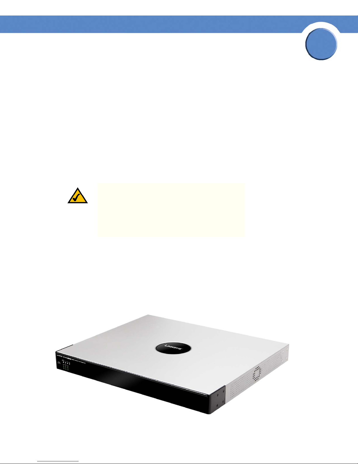
Features
The Linksys Business Series RPS1000 is shown in the figure below.
Chapter 2: Product Overview
Features
3
Page 7

Chapter
RPS1000—Business Series 380W RPS Unit Installation & Administration
The RPS1000 has these features:
• Six output channels to support multiple devices
• RPS1000 status information available through the network management application on the
device
• Front-panel LEDs to show status for each output channel, internal power supplies, fans, and
temperature
• Quick switch over capability to ensure that the switch does not reboot if the internal switch
power supply should fail
• Support for the SFE2000/2000P and SGE2000/2000P Ethernet switches
• Small form-factor suitable for rack-mounting to provide maximum wiring closet port density
• Two output levels:
– –48 VDC / 5.6A
2
– 12 VDC / 8.5A
The two output levels provide a maximum total output power of 380 W. The –48 VDC mode
powers telephone systems in Power over Ethernet (PoE) switches.
• A single 48-inch (1.2-meter) 16-pin-to-14-pin connector cable (part number: RPSCBL1) to
allow connection to an external device. Additional cables can be ordered separately.
Chapter 2: Product Overview
Features
4
Page 8

Chapter
RPS1000—Business Series 380W RPS Unit Installation & Administration
Front-Panel Description
The RPS1000 front panel includes the status LEDs for the RPS1000 and a STBY/ACTIVE button.
LEDs
The LEDs display the status of the RPS1000 and show whether the RPS1000 is powering a
connected device. LEDs can be off, green, or amber.
2
The six DC output LEDs display the status of the six output connectors that you use to connect to
supported devices. The output LEDs are numbered 1 to 6, which corresponds to the numbers on the
DC outputs.
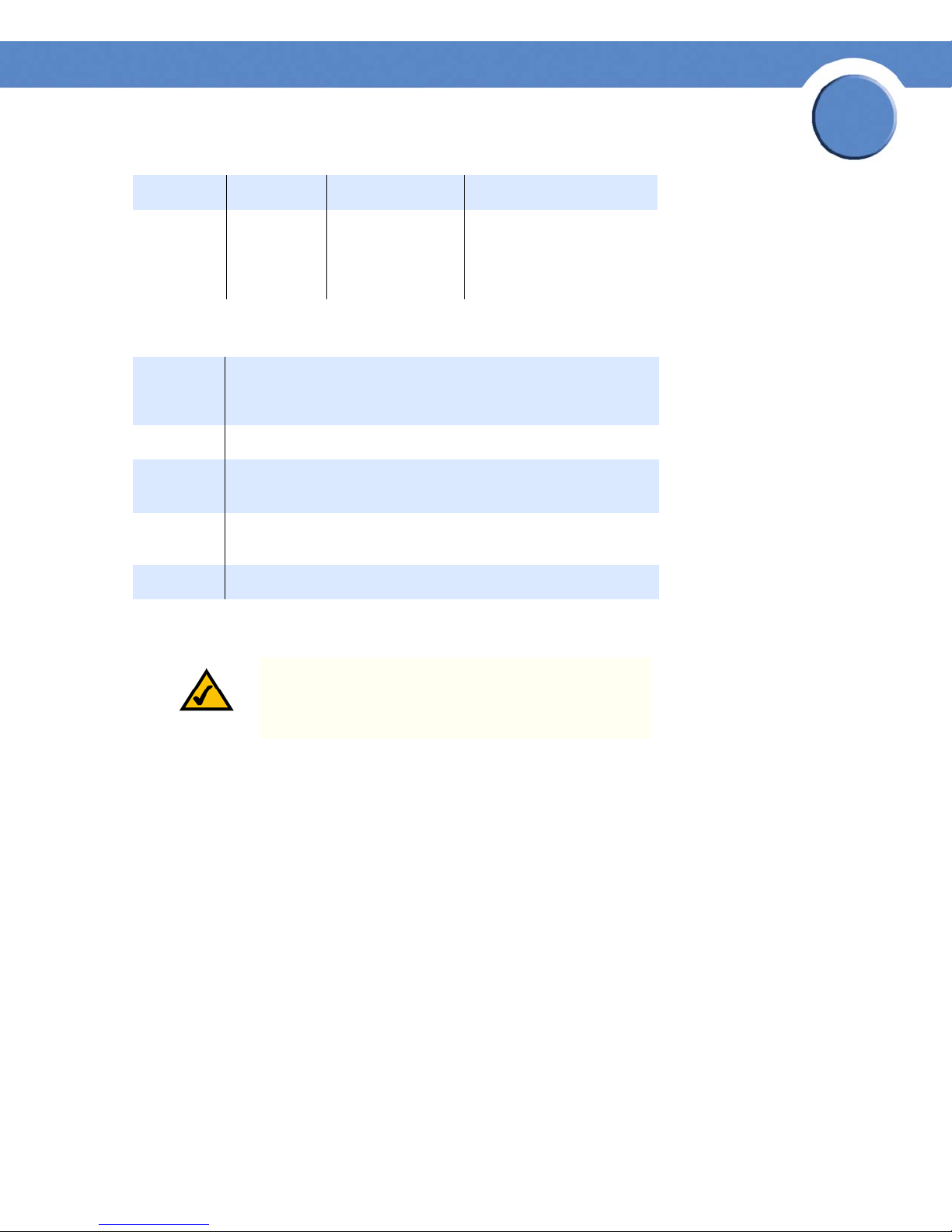
LED Off Green Amber
STBY/
ACTIVE
DC The
TEMP The
The
RPS1000 is
not powered
up.
RPS1000 is
not powered
up.
RPS1000 is
not powered
up.
The RPS1000 is in
active mode and
available to backup a failed
device.
The RPS1000
internal power
supplies are up
and running.
The RPS1000
internal
temperature is in
the acceptable
range.
(Blinking) The RPS1000 is
in standby mode. You can
connect devices to the
RPS1000, and it does not
attempt to back them up
until you press the STBY/
ACTIVE button and place
the RPS1000 into active
mode.
The DC output power is
not functioning correctly.
The RPS1000 is
approaching an overtemperature condition.
Chapter 2: Product Overview
Front-Panel Description
5
Page 9
RPS1000—Business Series 380W RPS Unit Installation & Administration
LED Off Green Amber
Chapter
2
FAN The
RPS1000 is
not powered
up.
The fan is
running.
The fan is not operating
properly.
STBY/ACTIVE Button
Color DC Output Status
Off No device is connected to the output connector.
Green A device is connected to the output connector.
Blinking
green
Blinking
amber
Amber The RPS1000 is in standby mode or in a fault condition.
The RPS1000 has a front panel STBY/ACTIVE button.
The RPS1000 is unavailable to the connected device. The
RPS1000 is providing power to another connected device.
The RPS1000 is providing power to the connected device; the
output is active.
NOTE: The RPS1000 is in active mode (STBY/ACTIVE
LED green) when it powers up. It must be in standby
mode every time you connect devices to it.
If you connect a device to the RPS1000 when it is in active mode (STBY/ACTIVE LED green), the
RPS1000 might unnecessarily begin supplying backup power to the device. This situation might
occur if you connect the device before it is powered up, or if the RPS1000 does not immediately
sense that the device power supply was supplying power. In this case, the RPS1000 would not be
available as a backup power source for other connected devices.
Press the STBY/ACTIVE button to change the RPS1000 from active mode to standby mode when you
connect devices. When you change the mode to active, the STBY/ACTIVE LED turns green.
Chapter 2: Product Overview
Front-Panel Description
6
Page 10

Chapter
RPS1000—Business Series 380W RPS Unit Installation & Administration
When you want to connect additional devices, press the STBY/ACTIVE button to place the RPS1000
in standby mode. The STBY/ACTIVE LED flashes amber. When you have connected and powered up
all devices, press the STBY/ACTIVE button again to put the RPS1000 into active mode.
NOTE: When the RPS1000 is in standby mode, all of the
DC Output LEDs are amber.
2
NOTE: When the RPS1000 is in standby mode, the
RPS1000 LED that is on the connected device is amber;
this means that the RPS1000 is connected but is not
functioning. When you press the STBY/ACTIVE button,
the RPS1000 LED that is on the connected device changes
to green to show that the RPS1000 is operating properly.
Rear-Panel Description
The RPS1000 rear panel has an AC power input connector and six DC output connectors (numbered
1 to 6) to connect to supported devices.
12 2 2 2 2 2 3
1 AC input connector
2 DC output connectors
3 Fan exhaust
Use the supplied AC power cord to connect to an AC power outlet.
The DC output connectors require a Cisco 16-pin-to-14-pin cable (RPSCBL1) to connect to supported
devices. (One cable is supplied with the RPS1000; you can order additional cables separately.) The
Chapter 2: Product Overview
Rear-Panel Description
7
Page 11

Chapter
Ethernet Switches
RPS1000—Business Series 380W RPS Unit Installation & Administration
16-pin connector plugs into the RPS1000, and the 14-pin connector plugs into the device. Use only
the Cisco cable for this connection.
WAR NI NG : Attach only the RPS1000 cable (part #
RPSCBL1) to the RPS1000 receptacle.
Deployment Strategies
You can deploy the RPS1000 in a variety of situations with mission-critical applications.
One application might be in a voice and data network in which Linksys Business Series switches are
connected to Linksys Business Series IP phones and PCs. Connecting an RPS1000 to the switches can
prevent voice network failures that are caused by switch failures.
Another application might be that of using traditional data 10/100/1000 Ethernet switches that
carry mission-critical data. These applications would typically use one RPS1000 to support one to
six switches as shown below.
2
RPS 1000
In this configuration, if one device has a power-supply or power-related failure, the RPS1000
immediately begins to supply power to this device and is no longer available as a backup power
source for the other devices. The RPS1000 sends status information to network management
software to alert the system administrator that the other devices are not supported until the failed
device or the power supply in the failed device is repaired or replaced.
Chapter 2: Product Overview
Deployment Strategies
DC output 6
DC output 1
81531
8
Page 12

Chapter
Ethernet Switches
RPS1000 RPS Units
RPS1000—Business Series 380W RPS Unit Installation & Administration
When the network supports mission-critical applications that require one-to-one redundancy, an
RPS1000 is connected to each supported device to ensure that each switch is always supported. This
one-to-one redundant configuration is shown below.
2
181532
Chapter 2: Product Overview
Deployment Strategies
9
Page 13

RPS1000—Business Series 380W RPS Unit Installation & Administration
Installation
This chapter describes how to install and connect the RPS1000 and includes these topics:
• Preparing for Installation
• Installing the Switch
• Connecting the RPS1000
Preparing for Installation
Read these sections and perform the procedures in the order that they are presented:
• Site Requirements
• Verifying the Package Contents
Chapter
3
Chapter 3: Installation
Preparing for Installation
10
Page 14

Warnings.
RPS1000—Business Series 380W RPS Unit Installation & Administration
WAR NI NG : To prevent the switch from overheating, do
not operate it in an area that exceeds the maximum
recommended ambient temperature of 113°F (45°C). To
prevent airflow restriction, allow at least 3 inches (7.6
cm) of clearance around the ventilation openings.
WAR NI NG : Before working on equipment that is
connected to power lines, remove jewelry (including
rings, necklaces, and watches). Metal objects will heat up
when connected to power and ground and can cause
serious burns or weld the metal object to the terminals.
WAR NI NG : If a RPS1000 is not connected to the switch,
install an RPS1000 connector cover on the back of the
switch.
Chapter
3
WAR NI NG : Do not work on the system or connect or
disconnect cables during periods of lightning activity.
WAR NI NG : Read the installation instructions before
connecting the system to the power source.
WAR NI NG : To prevent bodily injury when mounting or
servicing this unit in a rack, you must take special
precautions to ensure that the system remains stable. The
following guidelines are provided to ensure your safety:
• This unit should be mounted at the bottom of the
rack if it is the only unit in the rack.
• When mounting this unit in a partially filled rack,
load the rack from the bottom to the top with the
heaviest component at the bottom of the rack.
• If the rack is provided with stabilizing devices,
install the stabilizers before mounting or servicing
the unit in the rack.
Chapter 3: Installation
Preparing for Installation
11
Page 15

RPS1000—Business Series 380W RPS Unit Installation & Administration
WAR NI NG : This unit is intended for installation in
restricted access areas. A restricted access area can be
accessed only through the use of a special tool, lock and
key, or other means of security.
WAR NI NG : The plug-socket combination must be
accessible at all times, because it serves as the main
disconnecting device.
WAR NI NG : This equipment must be grounded. Never
defeat the ground conductor or operate the equipment in
the absence of a suitably installed ground conductor.
Contact the appropriate electrical inspection authority or
an electrician if you are uncertain that suitable grounding
is available.
Chapter
3
WAR NI NG : Only trained and qualified personnel should
be allowed to install, replace, or service this equipment.
WAR NI NG : Ultimate disposal of this product should be
handled according to all national laws and regulations.
WAR NI NG : No user-serviceable parts inside. Do not
open.
WAR NI NG : Installation of the equipment must comply
with local and national electrical codes.
In addition, you should always follow these guidelines:
• Do not work alone if potentially hazardous conditions exist.
• Never assume that power is disconnected from a circuit. Always check.
Chapter 3: Installation
Preparing for Installation
12
Page 16

Chapter
RPS1000—Business Series 380W RPS Unit Installation & Administration
Site Requirements
Be sure to observe these requirements as you determine where to place the RPS1000:
WAR NI NG : This unit is intended for installation in
restricted access areas. A restricted access area can be
accessed only through the use of a special tool, lock and
key, or other means of security.
For proper operation, where you locate the RPS1000 is extremely important. If the equipment is
placed too close together, the ventilation is inadequate, and panels are inaccessible, malfunctions
and shutdowns might result, and maintenance will be difficult.
Consider this information when you plan the location of the chassis:
• Provide for access to both the front and rear panels of the RPS1000.
• Make sure that the room where the RPS1000 operates has adequate ventilation. Ambient
air temperature might not cool equipment to acceptable operating temperatures without
adequate ventilation. See the RPS1000—Business Series 380W RPS Quick Installation
Guide for temperature requirements.
3
Verifying the Package Contents
NOTE: Carefully remove the contents from the shipping
container and check each item for damage. If any item is
missing or damaged, contact your Cisco representative
or reseller for support. Replace all packing material into
the shipping container and save it.
These items are shipped:
• The RPS1000
•This Linksys Business Series RPS1000 Redundant Power System Hardware Installation Guide
• Product Registration Card
• AC power cord
• One 16-pin-to-14-pin DC connector cable
• Mounting kit that contains:
– Four rubber feet for mounting the switch on a table
– Two mounting brackets
– Four Phillips flat-head screws for attaching the brackets to the switch
– Four Phillips truss-head screws for attaching the brackets to the switch
Chapter 3: Installation
Preparing for Installation
13
Page 17

RPS1000—Business Series 380W RPS Unit Installation & Administration
– Four Phillips machine screws for attaching the brackets to a rack
Installing the Switch
This section describes these installation procedures:
• Table or Shelf-Mounting, page 14
•Rack-Mounting, page14
Table or Shelf-Mounting
WAR NI NG : Do not stack the chassis on any other
equipment. If the chassis falls, it can cause severe bodily
injury and equipment damage.
Follow these steps to install your chassis on a table or shelf:
Chapter
3
1. Unpack the RPS1000.
2. Attach the rubber feet from the accessory kit into the round recesses that are located on the
bottom of the chassis.
3. Place the RPS1000 chassis on an appropriate table, shelf, or desktop.
NOTE: If you have questions or need assistance, see the
Appendix C, "Linksys Contact Information," section.
Rack-Mounting
To install the chassis in a 19-inch or 24-inch rack, follow the instructions described in these
procedures.
NOTE: A 24-inch rack requires optional mounting
hardware.
Chapter 3: Installation
Installing the Switch
14
Page 18

RPS1000—Business Series 380W RPS Unit Installation & Administration
Planning Your Rack-Mount Installation
WAR NI NG : To prevent bodily injury when mounting or
servicing this unit in a rack, you must take special
precautions to ensure that the system remains stable. The
following guidelines are provided to ensure your safety:
• This unit should be mounted at the bottom of the
rack if it is the only unit in the rack.
• When mounting this unit in a partially filled rack,
load the rack from the bottom to the top with the
heaviest component at the bottom of the rack.
• If the rack is provided with stabilizing devices,
install the stabilizers before mounting or servicing
the unit in the rack.
Consider this information when you plan your equipment rack installation:
Chapter
3
• Enclosed racks must have adequate ventilation. Make sure that the rack is not congested
because each unit generates heat. The intake ports of equipment that is located higher in the
rack can draw heat upward from the equipment that is located near the bottom of the rack.
An enclosed rack should have louvered sides and a fan to provide cooling air.
• When mounting a chassis in an open rack, make sure that the rack frame does not block the
intake or exhaust ports. If the chassis is installed on slides, check the position of the chassis
when it is seated in the rack.
• Baffles can isolate exhaust air from intake air, which also helps to draw cooling air through
the chassis. The best placement of the baffles depends on the airflow patterns in the rack,
which you can determine by experimenting with different configurations.
• When equipment installed in a rack (particularly in an enclosed rack) fails, try this test:
Operate the equipment by itself, if possible. Power off other equipment in the rack and in
adjacent racks to allow the unit under test a maximum of cooling air and clean power.
• Install the RPS1000 and the external devices to which it will connect in adjacent shelves in a
rack.
Tools and Equipment Required
To rack-mount the RPS1000, you need these tools and equipment:
• Number 12 Phillips screwdriver
• Number 8 Phillips screwdriver
• Screws for attaching the brackets to the RPS1000 and the RPS1000 to the rack
• Rack-mount brackets (19-inch or 24-inch) from the accessory kit
Chapter 3: Installation
Installing the Switch
15
Page 19

Chapter
RPS1000—Business Series 380W RPS Unit Installation & Administration
Attaching the Brackets to the RPS1000
The bracket orientation and the screws that you use depend on whether you are attaching the
brackets for a 19-inch or a 24-inch rack. Use two of the supplied screws to attach each bracket,
according to the following guidelines:
• For a 19-inch rack, use the supplied number-8 Phillips flat-head screws to attach the long
side of the bracket to the RPS1000.
• For a 24-inch rack, use the supplied number-8 Phillips truss-head screws to attach the short
side of the bracket to the RPS1000.
NOTE: If you install the switch in a 24-inch rack, an
optional bracket kit that is not included with the switch is
required. You can order a kit that contains the 24-inch
rack-mounting brackets and hardware from Cisco (part
number RCKMNT-1RU=).
You can install the RPS1000 into a rack with either the front panel or the rear panel facing forward.
3
NOTE: If you plan to use the optional cable guide, you
should mount the RPS1000 with the rear panel forward.
The following figures show how to attach a bracket to one side of the RPS1000 for installation into
19-inch or 24-inch racks with the front panel facing forward The device can also be mounted so that
the rear panel of the RPS1000 faces forward.
Chapter 3: Installation
Installing the Switch
16
Page 20

Chapter
RPS1000—Business Series 380W RPS Unit Installation & Administration
Mounting the RPS1000 in a Rack
After the brackets are attached to the RPS1000, use the four supplied number-12 Phillips machine
screws to securely attach the brackets to the rack, as shown below.
3
Connecting the RPS1000
CAUTION: Make sure that the RPS1000 is either in
standby mode or that the RPS1000 AC power is
disconnected before you connect the RPS1000 to a
switch. This precaution is necessary because when you
connect the RPS1000 to the AC power, the RPS1000
automatically becomes active.
NOTE: Do not use different power sources to power up
the RPS1000 and the connected device. If you connect to
separate AC power sources, reset conditions might occur.
Chapter 3: Installation
Connecting the RPS1000
17
Page 21

Chapter
RPS1000—Business Series 380W RPS Unit Installation & Administration
NOTE: The switch might restart when it changes from
RPS1000 power to its own internal power. This situation
might occur after the power supply on a switch fails, the
RPS1000 takes over, and the switch reverts to its own
power. We advise you to assume this possibility and plan
accordingly when you restart a switch using its internal
power after using the RPS1000 as backup power.
WAR NI NG : Before working on a system that has an on/
off switch, turn OFF the power and unplug the power
cord.
With the RPS1000 on a desktop or in a rack, connect devices as follows:
1. If the RPS1000 is already connected to AC power, press the STBY/ACTIVE button on the
RPS1000 to put it into standby mode or disconnect the RPS1000 from the AC power. If you
pressed the STBY/ACTIVE button, the STBY/ACTIVE LED should begin blinking amber. If the
STBY/ACTIVE LED does not blink amber, see Chapter B, "Troubleshooting".
3
2. Connect one end of an RPS1000 connector cable (part number: RPSCBL1) to an RPS1000 DC
output connector. To ensure proper operation, be sure that you completely seat the connector
and that you securely tighten the screw.
NOTE: The connector is designed to be inserted into the
receptacle in its correct orientation.
WAR NI NG : Attach only the Cisco RPS1000 (model
PWR675-AC-RPS-N1) to the RPS1000 receptacle.
3. Connect the other end of the RPS1000 connector cable to the RPS1000 receptacle on the switch.
4. Repeat 2. through 3. for each switch that the RPS1000 will support.
Chapter 3: Installation
Connecting the RPS1000
18
Page 22

Chapter
RPS1000—Business Series 380W RPS Unit Installation & Administration
5. Connect all supported devices to an AC power source.
NOTE: The RPS1000 is designed to provide backup for
internal power supply failures of connected device power
supplies. It is not designed to act as a backup power
source that protects against losses of power due to
external power outages. We recommend using an
uninterruptable power system (UPS) as protection against
power outages.
6. If the RPS1000 is not already connected to AC power, connect the AC power cable to the
RPS1000, and connect the other end of the power cable to an AC power source.
7. Press the RPS1000 STBY/ACTIVE button to put the RPS1000 into active mode.
The STBY/ACTIVE, Output Power, Temperature, and Fan LEDs on the RPS1000 front panel should be
green. The DC Output LEDs for the connected devices should also be green. If they are not green,
see “LEDs” section on page 5 for the appropriate action to take.
3
Chapter 3: Installation
Connecting the RPS1000
19
Page 23

RPS1000—Business Series 380W RPS Unit Installation & Administration
Technical Specifications
The following table lists the technical specifications for the RPS1000.
Environmental Ranges
Appendix
A
Operating temperature
Storage temperature
Operating humidity
Storage humidity
Operating altitude
Storage altitude
Power Requirements
AC input voltage
Power delivery (available
power) Total
Standby power
KVA
32 to 113°F (0 to 45°C)
–4 to 149°F (–20 to 65°C)
10 to 85% (noncondensing)
5 to 95% (noncondensing)
Up to 10,000 ft (3,000 m)
Up to 15,000 ft (4,570 m)
100 to 240 VAC (auto ranging)
6 to 10 A, 50 to 60 Hz
875 W
375 W per –48 VDC output and
300 W per 12 VDC output
25 W
0.875 KVA
Physical Dimensions
Weight
Dimensions (H x W x D)
Safety EMC
UL 60950 FCC Part 15 Class A
CAN/CSA 22.2 No. 60950 BSMI
IEC 60950/EN 60950 EN 55022: 1998 (CISPR22) Class A
Appendix A:
11.5 lb. (5.22 kg)
1.75 x 17.5 x 14.88 in.
(4.45 x 44.45 x 37.8 cm)
20
Page 24

RPS1000—Business Series 380W RPS Unit Installation & Administration
AS/NZS 3260, TS001 EN 55024: 1998 (CISPR24)
CE VCCI Class A
CCC approval pending AS/NZS 3548 Class A
CLEI code CE
NOM CNS 13438 Class A
MIC
Appendix
A
Appendix A:
21
Page 25

Appendix
RPS1000—Business Series 380W RPS Unit Installation & Administration
Troubleshooting
The RPS1000 is not repairable in the field. The following table shows the appropriate action to take
for specific LED indications.
Symptom Condition Action
B
STBY/ACTIVE LED is
blinking amber.
STBY/ACTIVE LED is
off.
Output Power LED is
amber.
Temper at ur e LE D i s
amber.
Fan LED is amber.
One or more DC
Output LEDs are
blinking green.
The RPS1000 is in standby mode.
The AC power connection to one
or both of the internal power
supplies is faulty or not connected.
The DC output power from the
internal power supplies is not
available or is not functioning
correctly.
The RPS1000 is approaching an
over-temperature condition.
The fan is not operating properly. The fan is defective. Replace the RPS1000.
The RPS1000 is unavailable to the
connected device. It is either
providing power to another
connected device or a fault
condition exists.
Press the STBY/ACTIVE button to put the
RPS1000 in active mode.
Check the AC power connection to
external power.
If the AC power is connected properly, the
problem might be with the RPS1000
internal power supplies.
An internal power supply is defective, or
the RPS1000 has reacted to an overcurrent condition. Press the STBY/ACTIVE
button. If the LED color does not turn
green, replace the RPS1000.
Reduce the ambient temperature.
Verify that the RPS1000 is supplying
power to one device. If so, this is a normal
indication and will change when that
external device is again supplying its own
power and you press the STBY/ACTIVE
button.
One or more DC
Output LEDs are
solid amber.
Appendix B:
The RPS1000 is in standby mode.
Press the STBY/ACTIVE button to put the
RPS1000 into active (or ready) mode.
22
Page 26

Appendix
RPS1000—Business Series 380W RPS Unit Installation & Administration
Linksys Contact Information
Need to contact Linksys?
Visit us online for information on the latest products and updates to your existing products at:
http://www.linksys.com/international
If you experience problems with any Linksys product, you can e-mail us at:
In Europe E-mail Address
Austria support.at@linksys.com
Belgium support.be@linksys.com
Czech Republic support.cz@linksys.com
C
Denmark support.dk@linksys.com
Finland support.fi@linksys.com
France support.fr@linksys.com
Germany support.de@linksys.com
Greece support.gr@linksys.com (English only)
Hungary support.hu@linksys.com
Ireland support.ie@linksys.com
Italy support.it@linksys.com
Netherlands support.nl@linksys.com
Norway support.no@linksys.com
Poland support.pl@linksys.com
Portugal support.pt@linksys.com
Russia support.ru@linksys.com
Spain support.es@linksys.com
Sweden support.se@linksys.com
Switzerland support.ch@linksys.com
United Kingdom support.uk@linksys.com
Appendix C:
23
Page 27

RPS1000—Business Series 380W RPS Unit Installation & Administration
Outside of Europe E-mail Address
Asia Pacific asiasupport@linksys.com (English only)
Appendix
C
Latin America
Middle East & Africa support.mea@linksys.com (English only)
South Africa support.ze@linksys.com (English only)
UAE support.ae@linksys.com (English only)
U.S. and Canada support@linksys.com
support.portuguese@linksys.com or
support.spanish@linksys.com
Appendix C:
24
Page 28

Appendix
Top of Connector (Logo Side)
50211
Top of Connector (Logo Side)
86671
RPS1000—Business Series 380W RPS Unit Installation & Administration
Connector and Cable
Specifications
This appendix describes the cable connector that is used to connect the RPS1000 to a supported
device. The cable (CAB-RPS-1614=) is a 48-inch (1.2-meter) cable with a 16-pin connector on one
end and a 14-pin connector on the other end. The following figures show the pinout information.
TIP: The connector is keyed to insert into the receptacle
only in its correct orientation.
14-Pin Connector Pinouts
D
8 9 10 11 12 13 14
1234567
16-Pin Connector Pinouts
9 101112131415
1234567168
Pin Number 14-Pin Designation 16-Pin Designation
1 GND GND–48 V
2 –48 V –48 V
3 12 V 12 V
Appendix D:
25
Page 29

RPS1000—Business Series 380W RPS Unit Installation & Administration
Pin Number 14-Pin Designation 16-Pin Designation
412 V 12 V
5 12 V 12 V
612 V 12 V
7 GND GND–12
8GND GND–12
9 –48 V GND–48 V
10 RPS_PRES (RPS1000 present) –48 V
11 RPS_CTRL 0 RPS_PRES (RPS1000 present)
12 RPS_CTRL 1 RPS_CTRL 0
Appendix
D
13 PWR_GOOD (power is good) RPS_CTRL 1
14 GND PWR_GOOD (power is good)
15 GND–12
16 GND–12 V
Appendix D:
26
Page 30

©2007 Cisco Systems, Inc. All rights reserved. Linksys is a registered trademark and the Linksys One logo is a trademark of Cisco Systems, Inc.
 Loading...