

Page 1
¸
SFE1000P 8-port 10/100 Ethernet Switch with
PoE Administration Guide
March 2008
SFE1000P 8-port 10/100 Ethernet Switch with PoE
Administration Guide
SFE1000P 8-PORT 10/100 ETHERNET SWITCH WITH POE ADMINISTRATION GUIDE
Page 2

© Copyright 2008, Cisco Systems, Inc.
Specifications are subject to change without notice.
Linksys, the Cisco Systems logo, the Linksys Logo, and the Linksys One logo are registered trademarks of Cisco
Systems, Inc. All other trademarks mentioned in this document are the property of their respective owners.
Document Revision History
Revision Date Description
1.0 March 2008 Initial release
Page 3

Contents
SFE1000P Gigabit Ethernet Switch Administration Guide
Chapter 1: Preface . . . . . . . . . . . . . . . . . . . . 1
Audience 1
Purpose 1
Organization 1
Chapter 2: Getting Started . . . . . . . . . . . . . . . . . 3
Starting the Application 3
Understanding the Interface 5
Device Representation 6
Using the Linksys Management Buttons 7
Using Screen and Table Options 7
Adding Device Information 7
Modifying Device Information 8
Deleting Device Information 8
Resetting the Device 9
Logging Off The Device 9
Chapter 3: Managing Device Information . . . . . . . . . . . 10
Understanding the Device Zoom View 10
Defining General System Information 11
Resetting the Device 11
Chapter 4: Managing Power-over-Ethernet Devices . . . . . . . . 13
Defining PoE Settings 13
Chapter 5: Configuring Device Security . . . . . . . . . . . . 15
Passwords Management 15
Modifying the Local User Settings 17
Defining Authentication 17
Defining Authentication Profiles 18
Modify the Authentication Profile 19
Mapping Authentication Profiles 19
Defining TACACS+ 20
Modifying TACACS+ Settings 22
Defining RADIUS 22
Modifying RADIUS Server Settings 24
Defining Access Method 24
Defining Access Profiles 24
Defining Profile Rules 26
Modifying Profile Rules 28
Defining Traffic Control 29
Defining Storm Control 29
Modifying Storm Control 30
Defining Port Security 30
Modifying Port Security 31
1
Page 4

Contents
SFE1000P Gigabit Ethernet Switch Administration Guide
Defining 802.1x 32
Defining Port Authentication 33
Modifying 8021X Security 34
Defining Multiple Hosts 35
Modifying Multiple Host Settings 35
Defining Authenticated Host 36
Defining Access Control 36
Defining MAC Based ACL 37
Adding Rule to MAC Based ACL 38
Defining IP Based ACL 38
Adding an IP Based Rule 40
Defining ACL Binding 40
Modifying ACL Binding 41
Defining DoS Prevention 41
Global Settings 42
Defining Martian Addresses 42
Chapter 6: Configuring Device Interfaces . . . . . . . . . . . . 44
Defining Port Settings 44
Modifying Port Settings 44
Defining LAG Management 45
Modifying LAG Membership 47
Defining LAG Settings 48
Configuring LACP 49
Modify LACP Parameter Settings 50
Chapter 7: Configuring VLANs . . . . . . . . . . . . . . . 51
Defining VLAN Properties 52
Modifying VLANs 53
Defining VLAN Membership 53
Modifying VLAN Membership 54
Defining Interface Settings 54
Modifying VLAN Interface Settings 55
Configuring GVRP Settings 55
Modifying GVRP Settings 56
Defining VLAN Protocol Group 57
Modifying Protocol Groups 58
Defining VLAN Protocol Port 58
Chapter 8: Configuring IP Information . . . . . . . . . . . . . 60
Domain Name System 60
Defining DNS Server 60
Mapping DNS Hosts 62
Configuring Layer 2IP Addresses 63
Configuring IP Addressing 63
Defining IP Interfaces 63
2
Page 5

Contents
SFE1000P Gigabit Ethernet Switch Administration Guide
Enabling ARP 64
Modifying ARP Settings 65
Chapter 9: Defining Address Tables . . . . . . . . . . . . . 66
Defining Static Addresses 66
Defining Dynamic Addresses 67
Chapter 10: Configuring Multicast Forwarding . . . . . . . . . 69
IGMP Snooping 69
Modifying IGMP Snooping 70
Defining Multicast Bridging Groups 70
Modifying a Multicast Group 72
Defining Multicast Forwarding 72
Modifying Multicast Forwarding 73
Chapter 11: Configuring Spanning Tree . . . . . . . . . . . . 74
Defining STP Properties 75
Defining Interface Settings 76
Modifying Interface Settings 77
Defining Rapid Spanning Tree 78
Modifying RTSP 79
Defining Multiple Spanning Tree 79
Defining MSTP Properties 80
Mapping MSTP Instances to VLAN 81
Defining MSTP Instance Settings 82
Defining MSTP Interface Settings 83
Chapter 12: Configuring SNMP . . . . . . . . . . . . . . . 85
Configuring SNMP Security 86
Defining the SNMP Engine ID 86
Defining SNMP Views 87
Defining SNMP Users 88
Modifying SNMP Users 89
Define SNMP Groups 89
Modifying SNMP Group Profile Settings 90
Defining SNMP Communities 91
Modifying SNMP Community Settings 92
Defining Trap Management 93
Defining Trap Settings 93
Configuring Station Management 93
Modifying SNMP Notifications Settings 96
Defining SNMP Filter Settings 96
Chapter 13: Configuring Quality of Service . . . . . . . . . . . 98
Defining General Settings 99
Defining CoS 100
3
Page 6

Contents
SFE1000P Gigabit Ethernet Switch Administration Guide
Modifying Interface Priorities 100
Defining Queue 101
Mapping CoS to Queue 101
Mapping DSCP to Queue 102
Configuring Bandwidth 103
Defining Advanced Mode 104
Configuring DSCP Mapping 105
Defining Class Mapping 106
Defining Aggregate Policer 107
Modifying QoS Aggregate Policer 108
Configuring Policy Table 109
Modifying the QoS Policy Profile 110
Defining Policy Binding 111
Modifying QoS Policy Binding Settings 112
Defining QoS Basic Mode 112
Chapter 14: Managing System Files . . . . . . . . . . . . 114
File Management Overview 114
File Management 115
Firmware Upgrade 115
Save Configuration 116
Copy Files 117
Active Image 118
Chapter 15: Managing System Logs . . . . . . . . . . . . 119
Enabling System Logs 119
Viewing the Device Memory Logs 121
Clearing Message Logs 121
Viewing the Flash Logs 122
Clearing Message Logs 122
Viewing Remote Logs 123
Modify Syslog Server Settings 124
Chapter 16: Configuring System Time . . . . . . . . . . . . 125
Defining System Time 125
Defining SNTP Settings 126
Defining SNTP Authentication 127
Chapter 17: Viewing Statistics . . . . . . . . . . . . . . . 128
Viewing Ethernet Statistics 128
Defining Ethernet Interface 128
Resetting Interface Statistics Counters 129
Viewing Etherlike Statistics 129
Resetting Etherlike Statistics Counters 129
Viewing GVRP Statistics 130
Resetting GVRP Statistics Counters 130
4
Page 7

Contents
SFE1000P Gigabit Ethernet Switch Administration Guide
Viewing EAP Statistics 131
Managing RMON Statistics 132
Viewing RMON Statistics 132
Resetting RMON Statistics Counters 132
Configuring RMON History 133
Defining RMON History Control 133
Modify History Control Settings 134
Viewing the RMON History Table 134
Configuring RMON Events 135
Defining RMON Events Control 135
Modify Event Control Settings 136
Viewing the RMON Events Logs 137
Defining RMON Alarms 137
Modify RMON Alarm Settings 139
Chapter 18: Managing Device Diagnostics . . . . . . . . . . 140
Viewing Integrated Cable Tests 140
Performing Optical Tests 141
Configuring Port Mirroring 142
Modifying Port Mirroring 143
Defining CPU Utilization 143
Appendix A: Console Interface Configuration . . . . . . . . . 144
Overview 144
Configuring the HyperTerminal Application 144
Connecting to the SFE1000P through a Telnet Session 147
Appendix B: Contacts . . . . . . . . . . . . . . . . . . 148
US/Canada Contacts 148
EU Contacts 148
Appendix C: Warranty Information . . . . . . . . . . . . . 149
LIMITED WARRANTY 149
Exclusions and Limitations 149
Obtaining Warranty Service 150
Technical Support 151
Appendix D: Regulatory Information . . . . . . . . . . . . 152
Federal Communications Commission Interference Statement 152
Industry Canada Statement 152
Règlement d’Industry Canada 153
EC Declaration of Conformity (Europe) 153
User Information for Consumer Products Covered by EU Directive 2002/96/EC on
Waste Electric and Electronic Equipment (WEEE) 153
Appendix E: Environmental Specifications . . . . . . . . . . 161
5
Page 8

Contents
SFE1000P Gigabit Ethernet Switch Administration Guide
Appendix F: Safety Information . . . . . . . . . . . . . . 162
Meaning of the Warning Symbol 162
General Safety Information 162
Appendix G: Software License Agreement . . . . . . . . . . 164
Software in Linksys Products: 164
Software Licenses: 164
Schedule 1 Linksys Software License Agreement 164
Schedule 2 166
Schedule 3 171
6
Page 9

Chapter
SFE1000P Gigabit Ethernet Switch Administration Guide
Preface
Audience
This publication is designed for people who have some experience installing networking equipment
such as routers, hubs, servers, and switches. We assume the person installing and troubleshooting
the SFE1000P is familiar with electronic circuitry and wiring practices and has experience as an
electronic or electromechanical technician.
Purpose
This guide documents the features of the Linksys Business Series SFE1000P Gigabit Ethernet Switch
(SFE1000P). It describes the administration of the SFE1000P, explains how to install the SFE1000P,
and provides configuration information.
Organization
1
This guide is organized into the following chapters:
• Chapter 2, "Getting Started,"is an introduction to the user interface.
• Chapter 3, "Managing Device Information,"provides information for defining both basic
and advanced system information.
• Chapter 4, "Managing Power-over-Ethernet Devices,"describes configuring PoE settings.
• Chapter 5, "Configuring Device Security,"describes password management, defining
authentication, access method, traffic control, 802.1x protocols, access control, and Denial
of service prevention.
• Chapter 6, "Configuring Device Interfaces,"describes defining port settings, LAG
management, LAG settings, and configuring LACP.
• Chapter 7, "Configuring VLANs," provides information for defining VLAN properties,
VLAN memberships, interface settings, and GVRP settings.
• Chapter 8, "Configuring IP Information," provides information for defining device IP
addresses.
• Chapter 9, "Defining Address Tables," contains information for defining both static and
dynamic Forwarding Database entries.
• Chapter 10, "Configuring Multicast Forwarding," contains information on configuring
IGMP snooping, defining multicast bridging groups, and multicast forwarding.
• Chapter 11, "Configuring Spanning Tree," contains information on configuring Spanning
Tree Protocol with classic STP, Rapid STP, and Multiple STP.
• Chapter 12, "Configuring SNMP," describes how to configure SNMP security and define
trap management.
Chapter 1: Preface
Audience
1
Page 10

Chapter
SFE1000P Gigabit Ethernet Switch Administration Guide
• Chapter 13, "Configuring Quality of Service," shows how to define Quality of Service
general settings, advanced mode settings, and basic mode settings. It also describes
configuring policy tables.
• Chapter 14, "Managing System Files," describes working with file management, logs, and
diagnostics.
• Chapter 15, "Managing System Logs," shows how to enable system logs, view device
memory logs, flash logs, and remote logs.
• Chapter 16, "Configuring System Time," provides information for configuring the system
time, and includes defining system time, SNTP settings, and SNTP authentication.
• Chapter 17, "Viewing Statistics," describes viewing and managing device statistics for
RMON, interfaces, GVRP, EAP, and Etherlike statistics.
• Chapter 18, "Managing Device Diagnostics," contains information for configuring port
mirroring, running cable tests, and viewing device operational information.
• Appendix B, "Contacts," is a listing of support resources and contact information for such.
1
• Appendix C, "Warranty Information," is the Linksys warranty.
Chapter 1: Preface
Organization
2
Page 11
Chapter
186906
SFE1000P Gigabit Ethernet Switch Administration Guide
Getting Started
This section provides an introduction to the user interface, and includes the following topics:
• Starting the Application
• Understanding the Interface
• Using the Linksys Management Buttons
• Using Screen and Table Options
• Resetting the Device
• Logging Off The Device
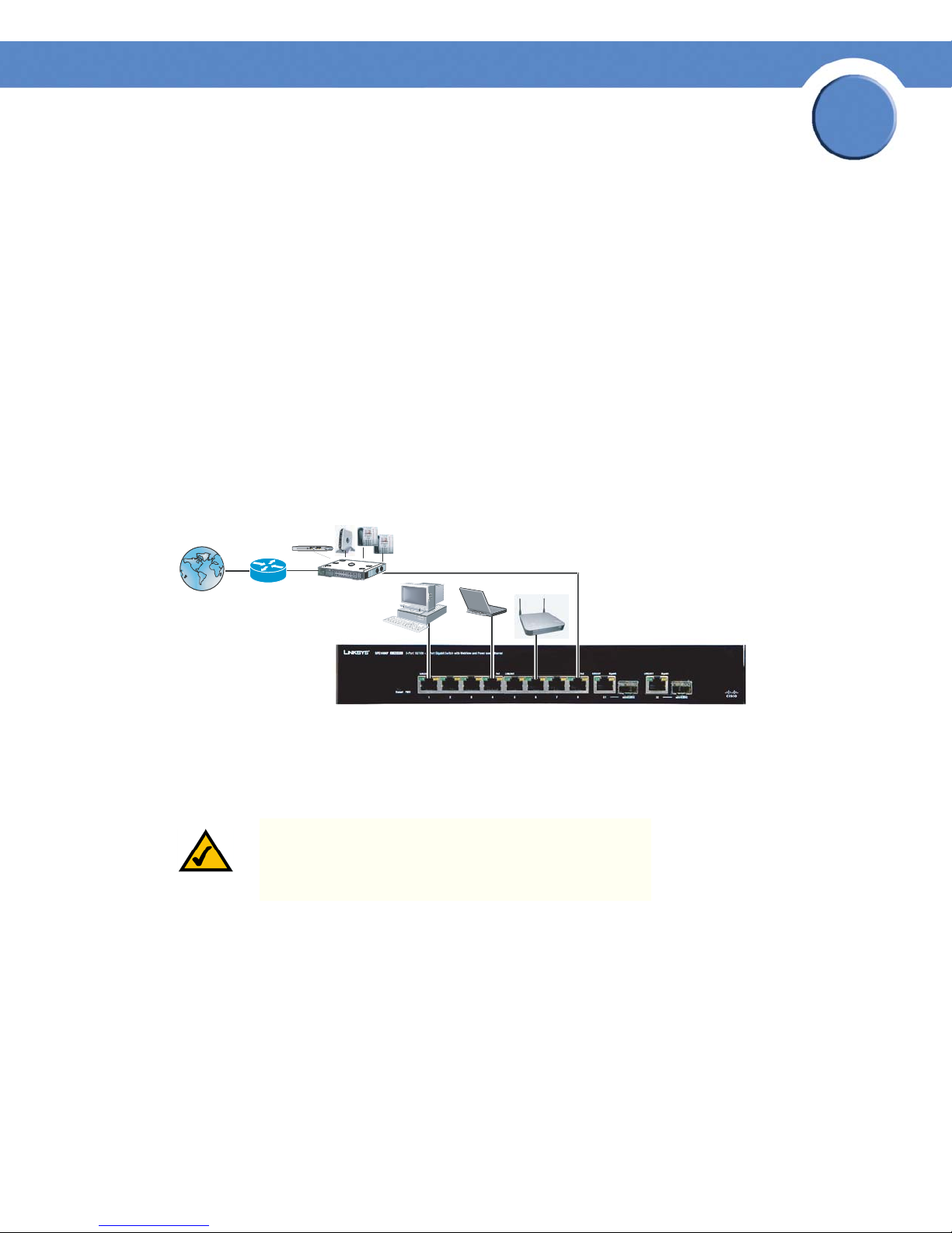
The following diagram illustrates how the SFE1000P fits into your network.
2
Starting the Application
This section contains information for starting the Linksys User Interface.
NOTE: By default, the IP address of the device is assigned
dynamically. The IP address can be changed.
To open the User Interface:
1. Open a web browser.
2. Enter the device’s IP address in the address bar and press Enter. An "Enter Network Password
Page" opens:
Chapter 2: Getting Started
Starting the Application
3
Page 12

SFE1000P Gigabit Ethernet Switch Administration Guide
Enter Network Password Page
Chapter
2
3. Enter a user name and password. The default user name is "admin"
configured with a default password, and can be configured without entering a password.
Passwords are both case sensitive and alpha-numeric.
4. Click Login The Embedded Web System Home Page opens:
NOTE: If you have logged in automatically via the Service
Router user interface, the Tree and Device views appear
and allow you to navigate through the various areas of
the web interface. However, the following page will
appear within the frame provided by the Service Router
user interface.
. The device is not
Chapter 2: Getting Started
Starting the Application
4
Page 13
SFE1000P Gigabit Ethernet Switch Administration Guide
Embedded Web System Home Page
Chapter
2
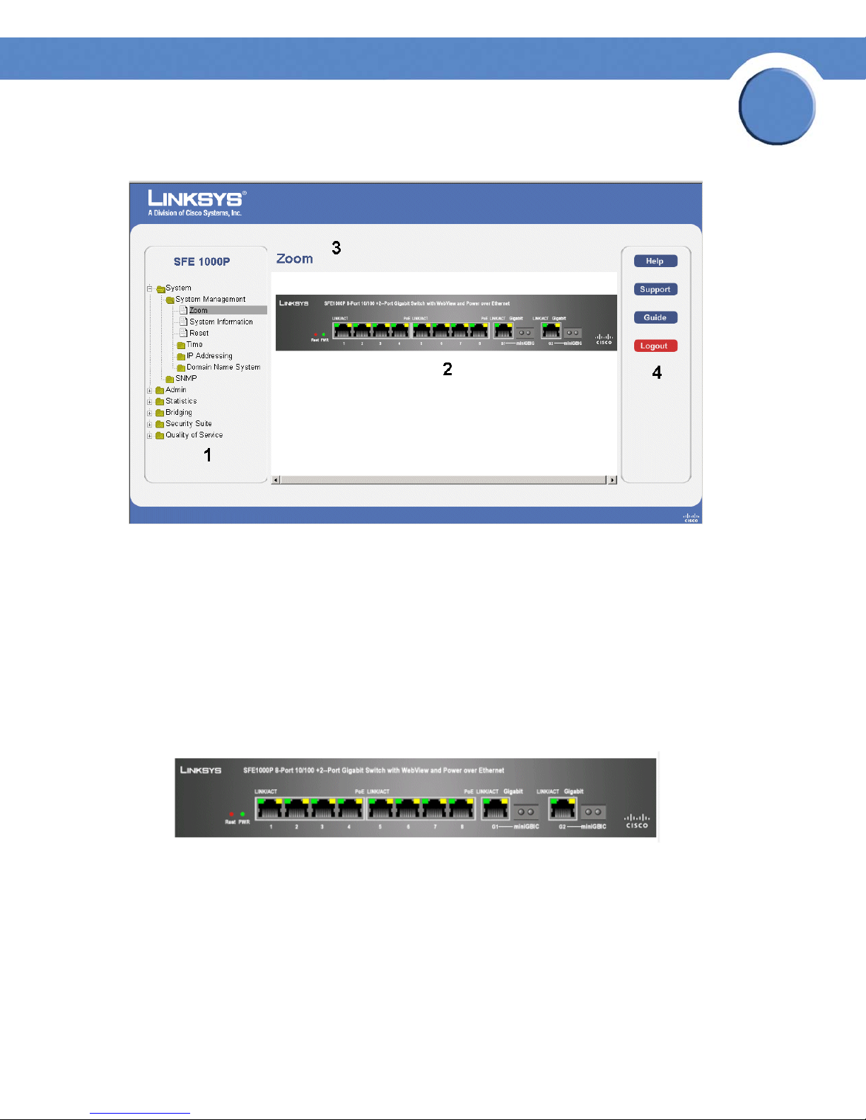
Understanding the Interface
The following table lists the interface components with their corresponding numbers:
Interface Components
Component Description
Tree View The Tree View provides easy navigation through the configurable
1
device features.The main branches expand to provide the subfeatures.
2 Device View The device view provides information about device ports, current
configuration and status, table information, and feature
components.The device view also displays other device information
and dialog boxes for configuring parameters.
3 Table Area The Table area enables navigating through the different device
features. Click the tabs to view all the components under a specific
feature.
4 EWS Information The EWS information tabs provide access to the online help, contains
information about the EWS.
Chapter 2: Getting Started
Understanding the Interface
5
Page 14
SFE1000P Gigabit Ethernet Switch Administration Guide
Linksys User Interface Components
Chapter
2
This section provides the following additional information:
•
Device Representation — Provides an explanation of the Linksys user interface buttons, including both
management buttons and task icons.
Using the Linksys Management Buttons — Provides instructions for adding, modifying, and deleting
•
device parameters.
Device Representation
The Linksys home page displays a graphical representation of the device:
Device Representation
The Linksys home page contains a graphical SFE1000 and SFE1000P front panel illustration.
Chapter 2: Getting Started
Understanding the Interface
6
Page 15

Chapter
SFE1000P Gigabit Ethernet Switch Administration Guide
Using the Linksys Management Buttons
Device Management buttons and icons provide an easy method of configuring device information,
and include the following:
Device Management Buttons
Button Name Button Description
Apply Applies changes to the device.
Clear Counters Clears statistic counters
Clear Logs Clears log files
2
Add Opens an Add page
Delete Removes entries from tables
Reset Resets the settlings of a selected
port to the default settings
Test Performs cable tests immediately.
Using Screen and Table Options
Linksys contains screens and tables for configuring devices. This section contains the following
topics:
•Adding Device Information
• Modifying Device Information
• Deleting Device Information
Adding Device Information
User defined information can be added to specific EWS pages, by opening a new Add page. To
add information to tables or EWS pages:
Chapter 2: Getting Started
Using the Linksys Management Buttons
7
Page 16
SFE1000P Gigabit Ethernet Switch Administration Guide
1. Open an EWS page.
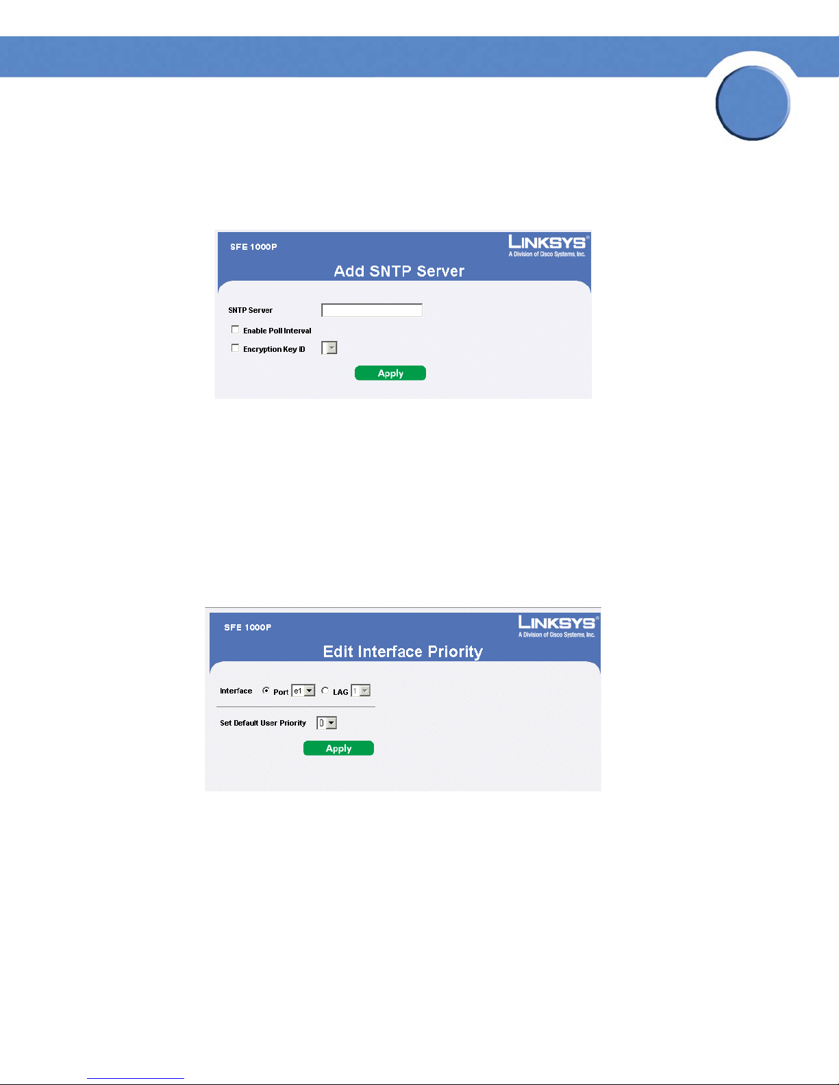
2. Click the Add button. An add page opens, for example, the Add SNTP Server Page:
Add SNTP Server
3. Define the fields.
4. Click Apply. The configuration information is saved, and the device is updated.
Chapter
2
Modifying Device Information
1. Open the EWS page.
2. Select a table entry.
3. Click the Edit Button. A Modify page opens, for example, the Interface Priority Page opens:
Edit Interface Priority
4. Define the fields.
5. Click Apply. The fields are modified, and the information is saved to the device.
Deleting Device Information
1. Open the EWS page.
2. Select a table row.
3. Check the Remove checkbox.
Chapter 2: Getting Started
Using Screen and Table Options
8
Page 17

Chapter
SFE1000P Gigabit Ethernet Switch Administration Guide
4. Click the Delete button. The information is deleted, and the device is updated.
Resetting the Device
The Reset page enables the device to be reset from a remote location. Save all changes to the
Running Configuration file before resetting the device. This prevents the current device configuration
from being lost. To reset the device:
1. Click System > General > Reset. The Reset page opens.
Reset Page
2
2. Click the Reset button. The device is reset, and a prompt for a user name and password is
displayed.
3. Enter a user name and password to reconnect to the Web Interface, if the device is not part of a
full Linksys One system. If the device is part of a Linksys One system, login is automatically done
from the Service Router.
Logging Off The Device
Click . The system logs off. The Embedded Web System Home Page closes.
Chapter 2: Getting Started
Resetting the Device
9
Page 18
Chapter
SFE1000P Gigabit Ethernet Switch Administration Guide
Managing Device Information
This section provides information for defining both basic and advanced system information. This
section contains the following topics:
• Understanding the Device Zoom View
• Defining General System Information
• Resetting the Device
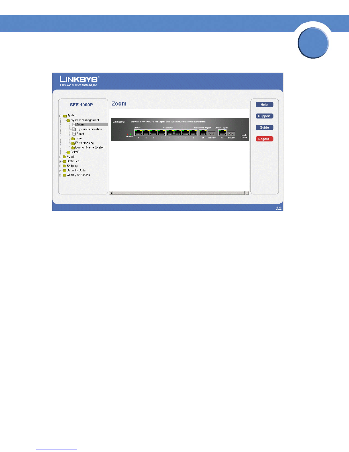
Understanding the Device Zoom View
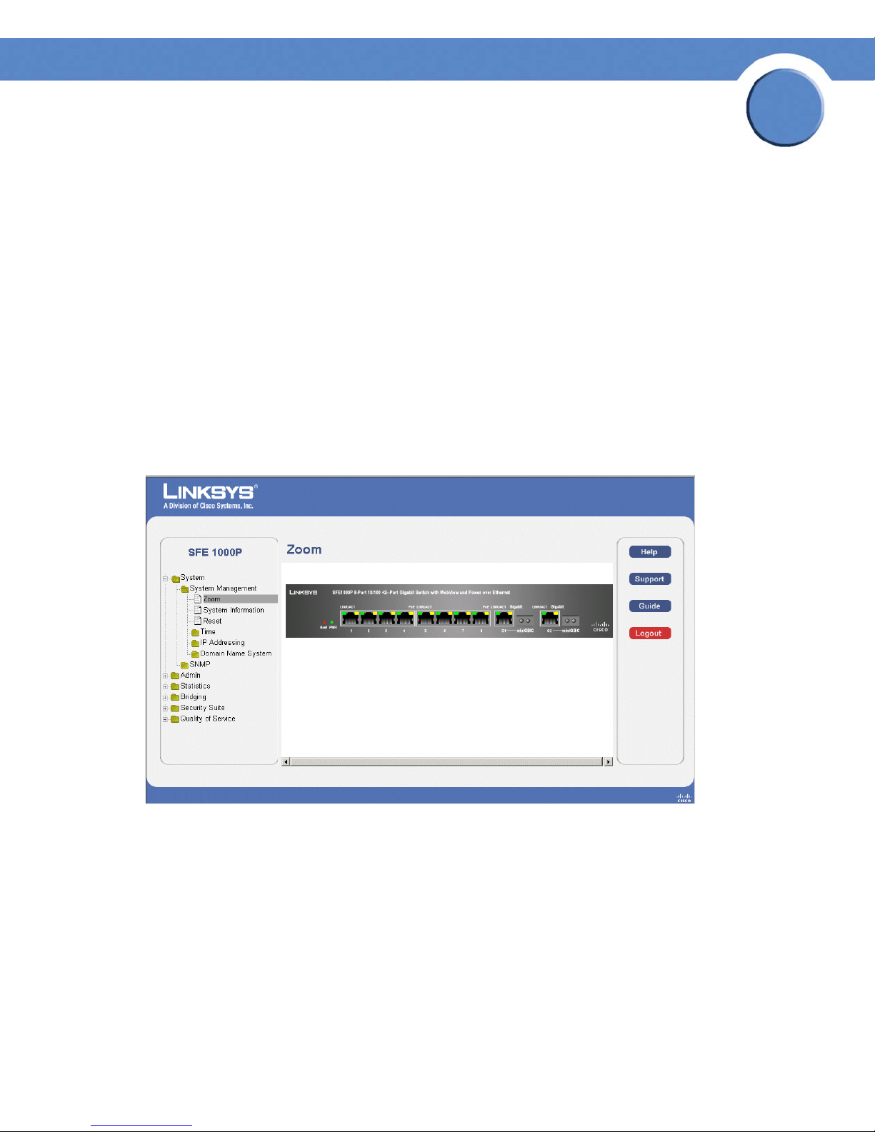
The Zoom Page is the main window used for viewing the device. To open the Zoom Page:
Click the System > System Management > Zoom. The Zoom Page opens:
Zoom Page
3
The Zoom Page contains the following port indicators:
• Green — Indicates the port is currently operating.
Chapter 3: Managing Device Information
Understanding the Device Zoom View
10
Page 19
Chapter
SFE1000P Gigabit Ethernet Switch Administration Guide
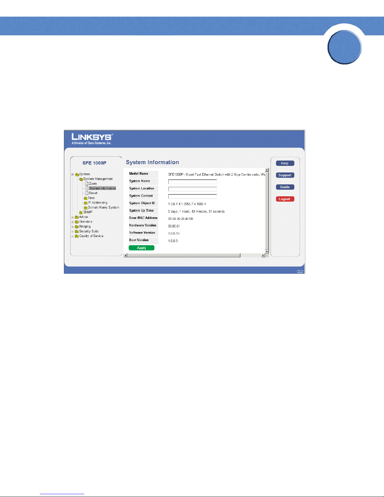
Defining General System Information
The System Information Page contains parameters for configuring general device information.
1. Click the System > System Management > System Information. The System Information Page
opens:
System Information Page
3
2. Enter information into the appropriate fields and press Apply.
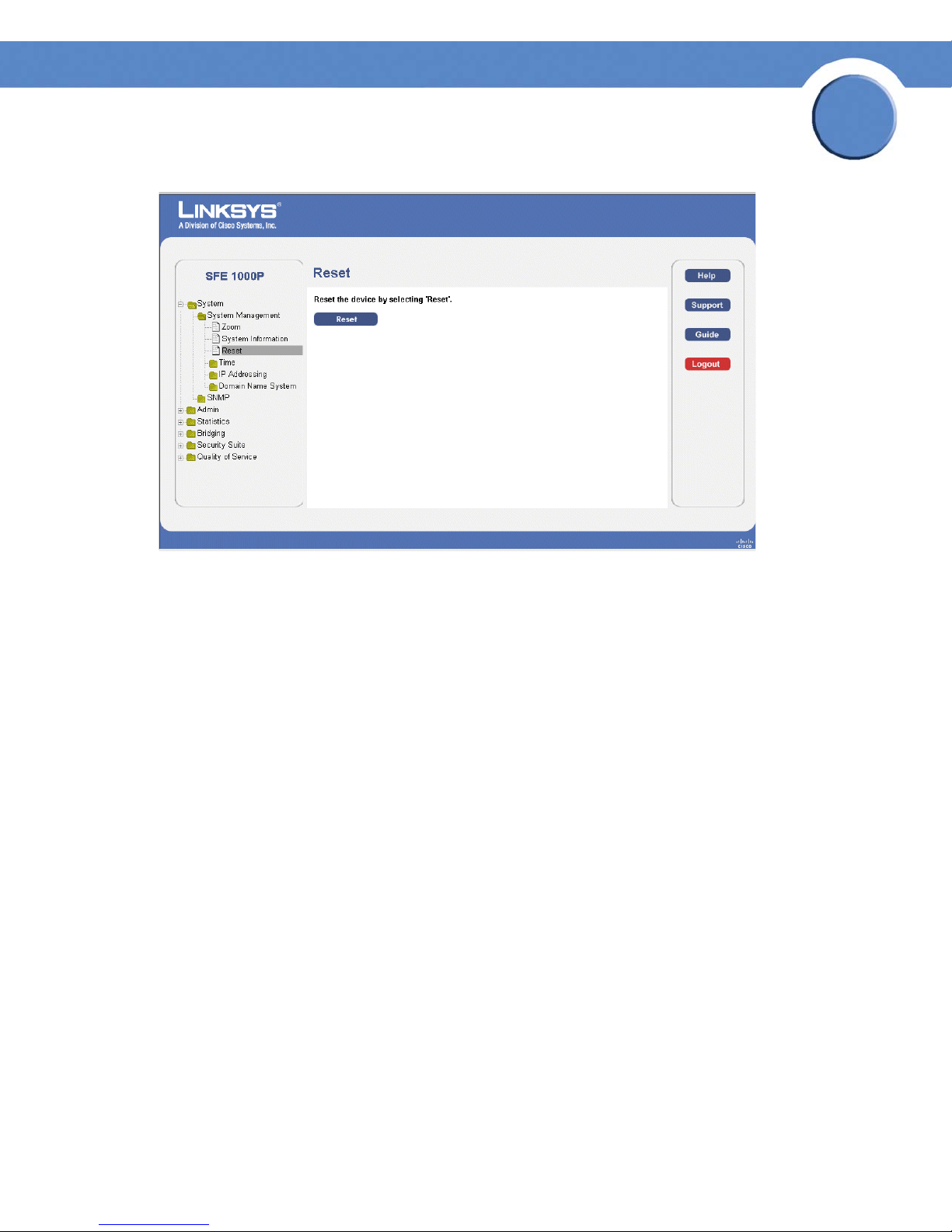
Resetting the Device
The Reset page enables the device to be reset from a remote location. Save all changes to the
Startup Configuration file before resetting the device. This prevents the current device configuration
from being lost.
To reset the device:
1. Click System > General > Reset. The Reset page opens.
Chapter 3: Managing Device Information
Defining General System Information
11
Page 20
Chapter
SFE1000P Gigabit Ethernet Switch Administration Guide
Reset Page
3
2. Click the Reset button.
3. Enter a user name and password to reconnect to the Web Interface. If the device is part of a
Linksys One system, login is automatically done from the Service Router.
Chapter 3: Managing Device Information
Resetting the Device
12
Page 21
Chapter
SFE1000P Gigabit Ethernet Switch Administration Guide
Managing Power-over-Ethernet Devices
Power-over-Ethernet (PoE) provides power to devices over existing LAN cabling, without updating or
modifying the network infrastructure. Power-over-Ethernet removes the necessity of placing network
devices next to power sources.
Power-over-Ethernet can be used in the following applications:
•IP Phones
• Wireless Access Points
•IP Gateways
•PDAs
• Audio and video remote monitoring
Defining PoE Settings
4
Powered Devices are devices which receive power from the device power supplies, for example IP
phones. Powered Devices are connected to the device via Ethernet ports. Guard Band protects the
device from exceeding the maximum power level. For example, if 400W is maximum power level,
and the Guard Band is 20W, if the total system power consumption exceeds 380W no additional
PoE components can be added. The accumulated PoE components power consumption is rounded
down for display purposes, therefore remove value after decimal point.
NOTE: Due to hardware limitations, the power
measurement accuracy is 4%.
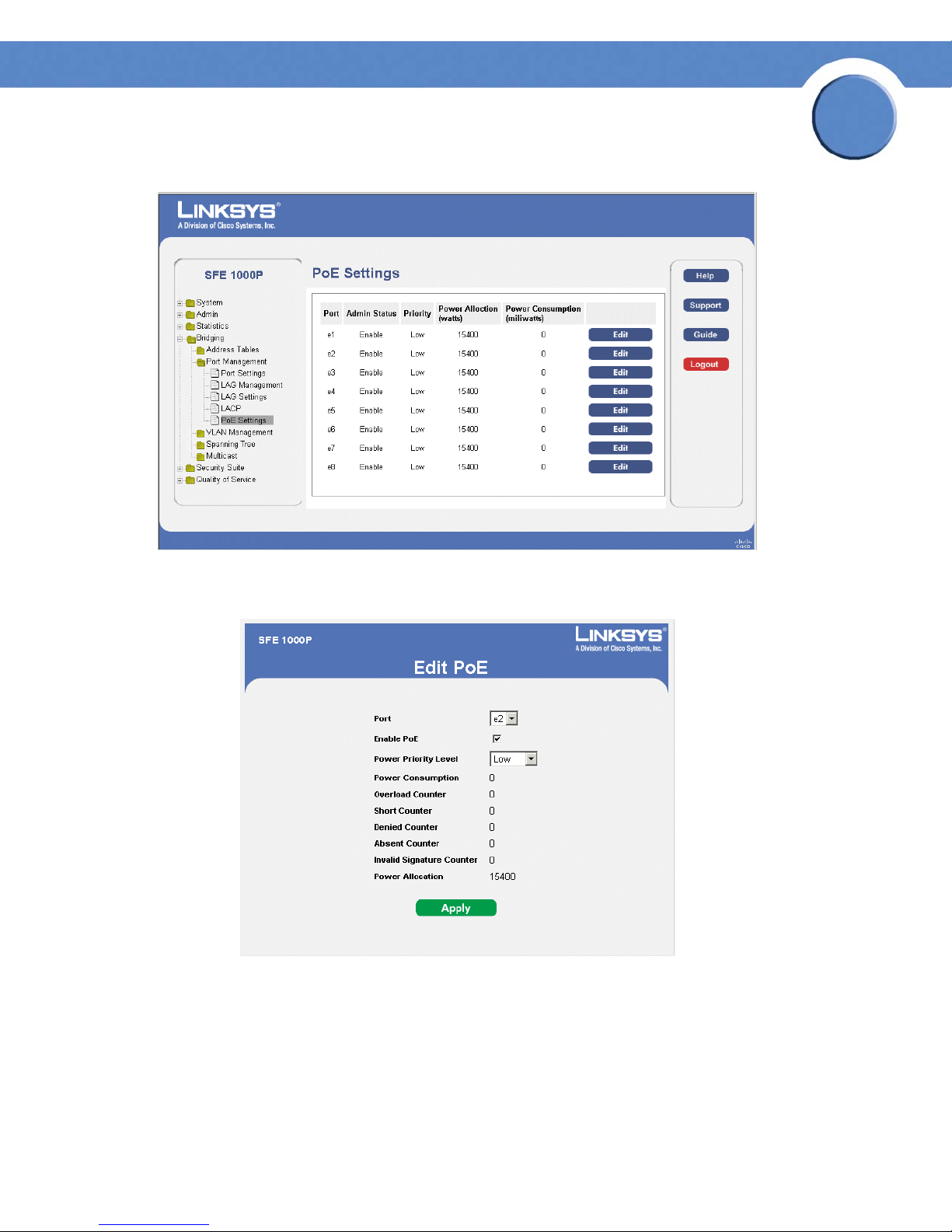
The PoE Settings Page contains system PoE information for enabling PoE on the device, monitoring
the current power usage, and enabling PoE traps.
1. Click Bridging > Port Management > PoE Settings. The PoE Settings Page opens:
Chapter 4: Managing Power-over-Ethernet Devices
Defining PoE Settings
13
Page 22
SFE1000P Gigabit Ethernet Switch Administration Guide
PoE Settings Page
Chapter
4
2. Click the Edit button. The Edit PoE opens:
Edit PoE
3. Define the relevant fields.
4. Click Apply. The PoE Settings are defined, and the device is updated.
Chapter 4: Managing Power-over-Ethernet Devices
Defining PoE Settings
14
Page 23
SFE1000P Gigabit Ethernet Switch Administration Guide
Configuring Device Security
The Security Suite contains the following sections:
• Passwords Management
• Defining Authentication
• Defining Access Method
• Defining Traffic Control
• Defining 802.1x
• Defining Access Control
• Defining DoS Prevention
Passwords Management
Chapter
5
This section contains information for defining passwords. Passwords are used to authenticate users
accessing the device.
NOTE: By default, a single user name is defined,
"admin", with no password. An additional user name/
password is configured for use in the system.
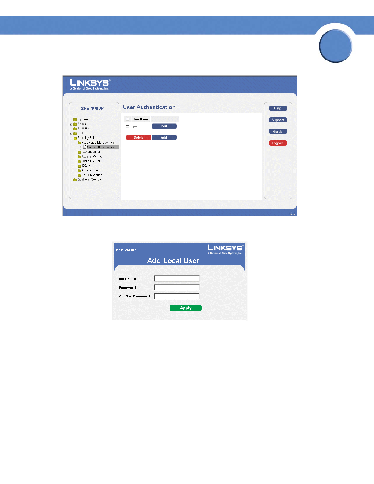
1. Click Security Suite > Passwords Management > User Authentication. The User Authentication
Page opens:
Chapter 5: Configuring Device Security
Passwords Management
15
Page 24
SFE1000P Gigabit Ethernet Switch Administration Guide
User Authentication Page.
Chapter
5
2. Click the Add button. The Add Local User Page opens:
Add Local User Page
3. Define the relevant fields.
4. Click Apply. The local user settings are modified.
Chapter 5: Configuring Device Security
Passwords Management
16
Page 25
Chapter
SFE1000P Gigabit Ethernet Switch Administration Guide
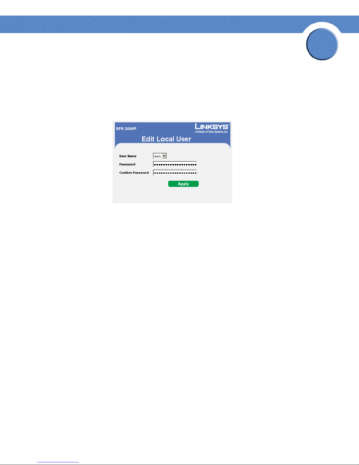
Modifying the Local User Settings
1. Click Security Suite > Passwords Management > User Authentication. The User Authentication
Page Opens:
2. Click the Edit Button. The Edit Local User Page opens:
Edit Local User Page
5
3. Define the relevant fields.
4. Click Apply. The local user settings are modified, and the device is updated.
Defining Authentication
The Authentication section contains the following pages:
• Defining Authentication Profiles
• Mapping Authentication Profiles
• Defining TACACS+
• Defining RADIUS
Chapter 5: Configuring Device Security
Defining Authentication
17
Page 26

Chapter
SFE1000P Gigabit Ethernet Switch Administration Guide
Defining Authentication Profiles
Authentication profiles allow network administrators to assign authentication methods for user
authentication. User authentication can be performed locally or on an external server. User
authentication occurs in the order the methods are selected. If the first authentication method is not
available, the next selected method is used. For example, if the selected authentication methods are
RADIUS and Local, and the RADIUS server is not available, then the user is authenticated locally.
1. Click Security Suite > Authentication > Profiles. The Profiles Page opens:
Profiles Page
5
2. Click the Add button. The Add Authentication Profile Page opens:
Add Authentication Profile Page
3. Define the relevant fields.
4. Click Apply. The settings are modified, and the device is updated.
Chapter 5: Configuring Device Security
Defining Authentication
18
Page 27
SFE1000P Gigabit Ethernet Switch Administration Guide
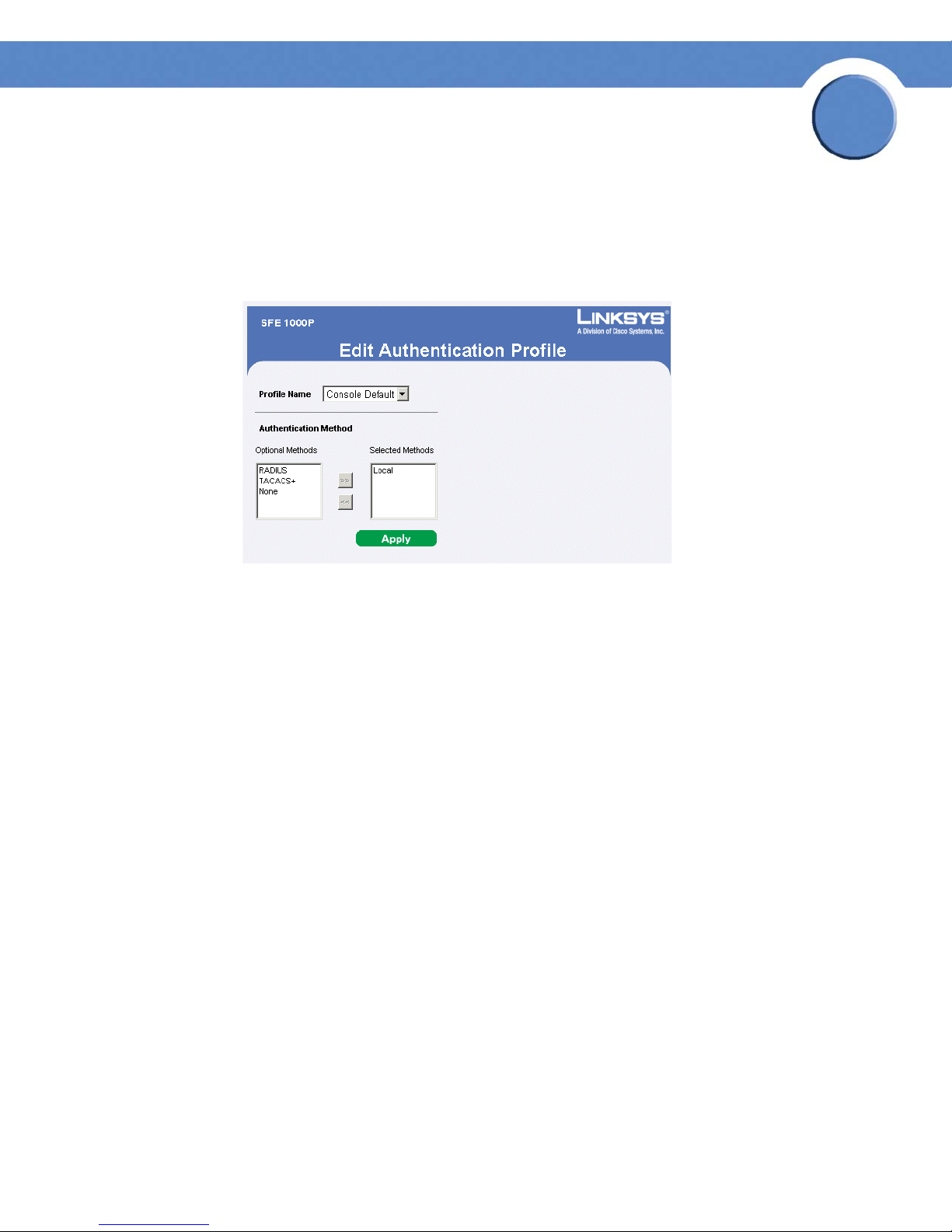
Modify the Authentication Profile
1. Click Security Suite > Authentication > Profiles. The Profiles Page opens:
2. Click the Edit Button. The Edit Authentication Profile Page opens:
Edit Authentication Profile Page
Chapter
5
3. Define the relevant fields.
4. Click Apply. The authentication profile is defined, and the device is updated.
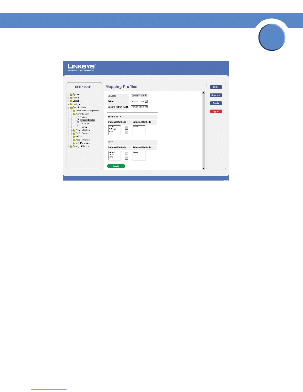
Mapping Authentication Profiles
After authentication profiles are defined, they can be applied to management access methods. For
example, console users can be authenticated by one authentication profile, while Telnet users are
authenticated by another authentication profile.
Authentication methods are selected using arrows. The order in which the methods are selected is
the order by which the authentication methods are used.
The Mapping Profiles Page contains parameters for mapping authentication methods.
1. Click Security Suite > Authentication > Mapping Profiles. The Mapping Profiles Page opens:
Chapter 5: Configuring Device Security
Defining Authentication
19
Page 28
SFE1000P Gigabit Ethernet Switch Administration Guide
Mapping Profiles Page
Chapter
5
2. Define the relevant fields.
3. Click Apply. Mapping Profiles is defined, and the device is updated.
Defining TACACS+
The devices provide Terminal Access Controller Access Control System (TACACS+) client support.
TACACS+ provides centralized security for validation of users accessing the device. TACACS+
provides a centralized user management system, while still retaining consistency with RADIUS and
other authentication processes. TACACS+ provides the following services:
• Authentication — Provides authentication during login and via user names and user-
defined passwords.
• Authorization — Performed at login. Once the authentication session is completed, an
authorization session starts using the authenticated user name. The TACACS server checks
the user privileges.
The TACACS+ protocol ensures network integrity through encrypted protocol exchanges between
the device and TACACS+ server.
The TACACS+ default parameters are user-assigned defaults. The default settings are applied to
newly defined TACACS+ servers. If default values are not defined, the system defaults are applied to
the new TACACS+ new servers. The TACACS+ Page contains fields for assigning the Default
Parameters for the TACACS+ servers.
Chapter 5: Configuring Device Security
Defining Authentication
20
Page 29
SFE1000P Gigabit Ethernet Switch Administration Guide
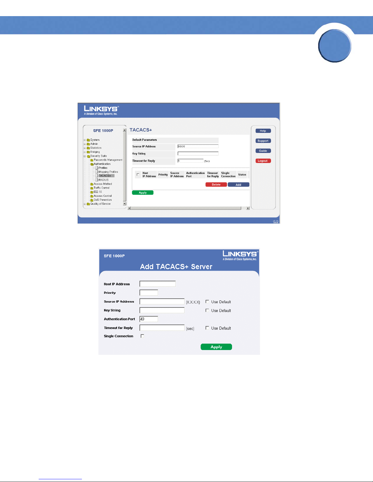
To d ef ine TACA CS +:
1. Click Security Suite > Authentication > TACACS+. The TAC ACS+ P age opens:
TACACS+ Page
Chapter
5
2. Click The Add button. The Add TACACS+ Server Page opens:
Add TACACS+ Server Page
3. Add a TACACS+ server.
4. Click Apply. The TACACS+ server is added, and the device is updated.
Chapter 5: Configuring Device Security
Defining Authentication
21
Page 30
Chapter
SFE1000P Gigabit Ethernet Switch Administration Guide
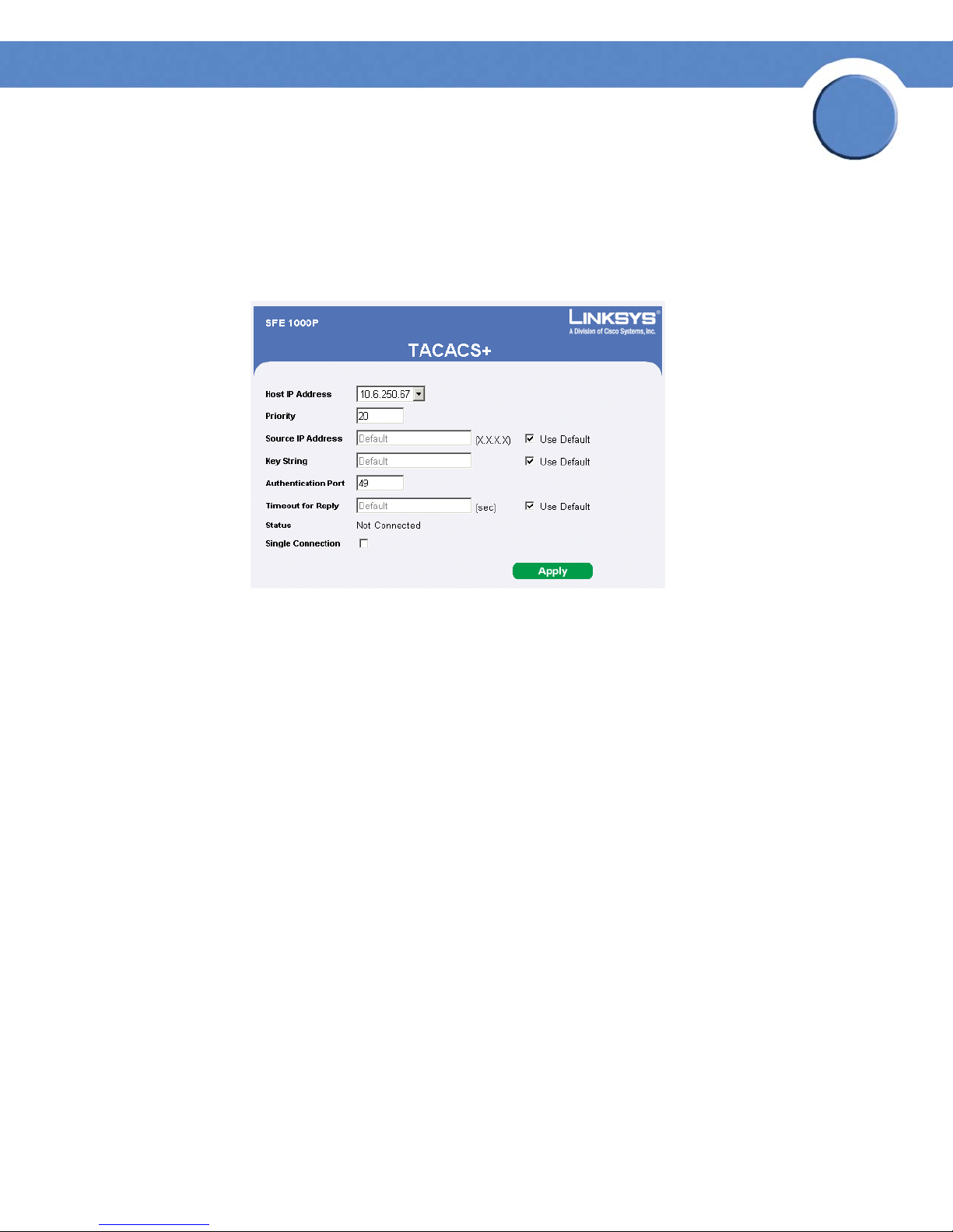
Modifying TACACS+ Settings
1. Click Security Management > Security Suite > Authentication. The TACACS+ Page opens:
2. Click the Edit Button. The TACACS+ Page opens:
TACACS+ Page
5
3. Define the relevant fields.
4. Click Apply. The TACACS+ settings are modified, and the device is updated.
Defining RADIUS
Remote Authorization Dial-In User Service (RADIUS) servers provide additional security for
networks. RADIUS servers provide a centralized authentication method for web access. The default
parameters are user-defined, and are applied to newly defined RADIUS servers. If new default
parameters are not defined, the system default values are applied to newly defined RADIUS servers.
To d ef ine RA DIU S :
1. Click Security Suite > Authentication > RADIUS. The RADIUS Page opens:
Chapter 5: Configuring Device Security
Defining Authentication
22
Page 31

SFE1000P Gigabit Ethernet Switch Administration Guide
RADIUS Page
Chapter
5
2. Click the Add button. The Add Radius Server Page opens:
Add Radius Server Page
3. Define the relevant fields.
4. Click Apply. The Radius Server is added, and the device is updated.
Chapter 5: Configuring Device Security
Defining Authentication
23
Page 32

SFE1000P Gigabit Ethernet Switch Administration Guide
Modifying RADIUS Server Settings
1. Click Security Suite > Authentication > RADIUS. The RADIUS Page opens:
2. Click the Edit button. The Edit RADIUS Settings Page opens:
Edit RADIUS Settings Page
Chapter
5
3. Define the relevant fields.
4. Click Apply. The RADIUS Server settings are modified, and the device is updated.
Defining Access Method
The access method section contains the following pages:
• Defining Access Profiles
• Defining Profile Rules
Defining Access Profiles
Access profiles are profiles and rules for accessing the device. Access to management functions can
be limited to user groups. User groups are defined for interfaces according to IP addresses or IP
subnets. Access profiles contain management methods for accessing and managing the device. The
device management methods include:
•All
•Telnet
• Secure Telnet (SSH)
• HTTP
Chapter 5: Configuring Device Security
Defining Access Method
24
Page 33

Chapter
SFE1000P Gigabit Ethernet Switch Administration Guide
• Secure HTTP (HTTPS)
•SNMP
Management access to different management methods may differ between user groups. For
example, User Group 1 can access the switch module only via an HTTPS session, while User Group
2 can access the switch module via both HTTPS and Telnet sessions. The Access Profile Page contains
the currently configured access profiles and their activity status. Assigning an access profile to an
interface denies access via other interfaces. If an access profile is assigned to any interface, the
device can be accessed by all interfaces.
To define access profiles:
1. Click Security Suite > Access Method > Access Profiles. The Access Profiles Page opens:
Access Profiles Page
5
2. Click the Add button. The Add Access Profile Page opens:
Chapter 5: Configuring Device Security
Defining Access Method
25
Page 34

3. Define the relevant fields.
SFE1000P Gigabit Ethernet Switch Administration Guide
Add Access Profile Page
Chapter
5
4. Click Apply. The access profile is added, and the device is updated.
Defining Profile Rules
Access profiles can contain up to 128 rules that determine which users can manage the switch
module, and by which methods. Users can also be blocked from accessing the device. Rules are
composed of filters including:
• Rule Priority
•Interface
• Management Method
• IP Address
•Prefix Length
• Forwarding Action
Chapter 5: Configuring Device Security
Defining Access Method
26
Page 35

SFE1000P Gigabit Ethernet Switch Administration Guide
To d ef ine pr ofil e rul es:
1. Click Security Suite > Access Method > Profile Rules. The Profile Rules Page opens:
Profile Rules Page
Chapter
5
2. Click the Add button. The Add Profile Rule Page opens:
Add Profile Rule Page
3. Define the relevant fields.
4. Click Apply. The profile rule settings are added, and the device is updated.
Chapter 5: Configuring Device Security
Defining Access Method
27
Page 36

SFE1000P Gigabit Ethernet Switch Administration Guide
Modifying Profile Rules
1. Click Security Suite > Access Method > Profile Rules. The Profile Rules Page opens:
2. Click the Edit button. The Edit Profile Rule Page opens:
Edit Profile Rule Page
Chapter
5
3. Define the relevant fields.
4. Click Apply. The profile rules are defined, and the device is updated.
Chapter 5: Configuring Device Security
Defining Access Method
28
Page 37

Chapter
SFE1000P Gigabit Ethernet Switch Administration Guide
Defining Traffic Control
The Traffic Control section contains the following pages:
• Defining Storm Control
• Defining Port Security
Defining Storm Control
Storm Control enables limiting the amount of Multicast and Broadcast frames accepted and
forwarded by the device. When Layer 2 frames are forwarded, Broadcast and Multicast frames are
flooded to all ports on the relevant VLAN. This occupies bandwidth, and loads all nodes connected
on all ports.
A Broadcast Storm is a result of an excessive amount of broadcast messages simultaneously
transmitted across a network by a single port. Forwarded message responses are heaped onto the
network, straining network resources or causing the network to time out.
5
Storm Control is enabled per all ports by defining the packet type and the rate the packets are
transmitted. The system measures the incoming Broadcast and Multicast frame rates separately on
each port and discards the frames when the rate exceeds a user-defined rate.
The Storm Control Page provides fields for configuring Broadcast Storm Control.
To define storm control:
1. Click Security Suite > Traf fic Control > Storm Control. The Storm Control Page opens:
Storm Control Page
2. Define the relevant fields.
3. Click Apply. Storm control is enabled, and the device is updated.
Chapter 5: Configuring Device Security
Defining Traffic Control
29
Page 38

SFE1000P Gigabit Ethernet Switch Administration Guide
Modifying Storm Control
1. Click Security Suite > Traf fic Control > Storm Control. The Storm Control Page opens:
2. Click the Edit Button. The Edit Storm Control Page opens:
Edit Storm Control Page
3. Modify the relevant fields.
Chapter
5
4. Click Apply. Storm control is modified, and the device is updated.
Defining Port Security
Network security can be increased by limiting access on a specific port only to users with specific
MAC addresses. The MAC addresses can be dynamically learned or statically configured. Locked
port security monitors both received and learned packets that are received on specific ports. Access
to the locked port is limited to users with specific MAC addresses. These addresses are either
manually defined on the port, or learned on that port up to the point when it is locked. When a
packet is received on a locked port, and the packet source MAC address is not tied to that port
(either it was learned on a different port, or it is unknown to the system), the protection mechanism is
invoked, and can provide various options. Unauthorized packets arriving at a locked port are
either:
•Forwarded
• Discarded with no trap
• Discarded with a trap
• Cause the port to be shut down.
Locked port security also enables storing a list of MAC addresses in the configuration file. The MAC
address list can be restored after the device has been reset. Disabled ports are activated from the
Port Management page.
NOTE: To configure port lock, 802.1x multiple host mode
must be enabled.
Chapter 5: Configuring Device Security
Defining Traffic Control
30
Page 39

SFE1000P Gigabit Ethernet Switch Administration Guide
Perform the following to define port security:
1. Click Security Suite > Traf fic Control > Port Security. The Port Security Page opens:
Port Security Page
Chapter
5
2. Define the relevant fields.
3. Click Apply. Port security is defined, and the device is updated.
Modifying Port Security
1. Click Security Suite > Traf fic Control > Port Security. The Port Security Page opens:
2. Click the Edit Button. The Edit Port Security Page opens:
Edit Port Security Page
3. Modify the relevant fields.
4. Click Apply. Port security is modified, and the device is updated.
Chapter 5: Configuring Device Security
Defining Traffic Control
31
Page 40

Chapter
SFE1000P Gigabit Ethernet Switch Administration Guide
Defining 802.1x
Port based authentication enables authenticating system users on a per-port basis via a external
server. Only authenticated and approved system users can transmit and receive data. Ports are
authenticated via the RADIUS server using the Extensible Authentication Protocol (EAP). Port
Authentication includes:
• Authenticators — Specifies the port, which is authenticated before permitting system access.
• Supplicants — Specifies host connected to the authenticated port requesting to access the
system services.
• Authentication Server — Specifies the external server, for example, the RADIUS server that
performs the authentication on behalf of the authenticator, and indicates whether the
supplicant is authorized to access system services.
Port based authentication creates two access states:
• Controlled Access — Permits communication between the supplicant and the system, if the
supplicant is authorized.
5
• Uncontrolled Access — Permits uncontrolled communication regardless of the port state.
The 802.1x page configures port to use Extensible Authentication Protocol (EAP).
The 802.1x section contains the following pages:
• Defining 802.1X Properties
• Defining Port Authentication
• Defining Multiple Hosts
• Defining Authenticated Host
The 802.1x page configures port to use Extensible Authentication Protocol (EAP).
Chapter 5: Configuring Device Security
Defining 802.1x
32
Page 41

SFE1000P Gigabit Ethernet Switch Administration Guide
1. Click Security Suite > 802.1X > Properties. The 802.1X Properties Page opens:
802.1X Properties Page
Chapter
5
2. Define the relevant fields.
3. Click Apply. The 802.1X properties are defined, and the device is updated.
Defining Port Authentication
1. Click Security Suite > 802.1X > Port Authentication. The 802.1X Properties Page opens:
802.1X Port Authentication Page
2. Define the relevant fields.
3. Click Apply. The port authentication settings are modified, and the device is updated.
Chapter 5: Configuring Device Security
Defining 802.1x
33
Page 42

SFE1000P Gigabit Ethernet Switch Administration Guide
Modifying 8021X Security
1. Click Security Suite > 802.1X > Properties. The 802.1X Properties Page opens:
2. Click the Edit button. The Port Authentication Settings Page opens:
Port Authentication Settings Page
Chapter
5
3. Modify the relevant fields.
4. Click Apply. The port authentication settings are defined, and the device is updated.
Chapter 5: Configuring Device Security
Defining 802.1x
34
Page 43

Chapter
SFE1000P Gigabit Ethernet Switch Administration Guide
Defining Multiple Hosts
The 802.1X Multiple Host Page allows network managers to configure advanced port-based
authentication settings for specific ports and VLANs.
1. Click Security Suite > 802.1X > Multiple Host. The 802.1X Multiple Host Page opens:
802.1X Multiple Host Page
5
2. Define the relevant fields.
3. Click Apply. The host settings are modified, and the device is updated.
Modifying Multiple Host Settings
1. Click Security Suite > 802.1X > Multiple Host. The 802.1X Properties Page opens:
2. Click the Edit button. The Edit Multiple Host Page opens:
Edit Multiple Host Page
3. Modify the relevant fields.
4. Click Apply. The multiple host settings are defined, and the device is updated.
Chapter 5: Configuring Device Security
Defining 802.1x
35
Page 44

Chapter
SFE1000P Gigabit Ethernet Switch Administration Guide
Defining Authenticated Host
The Authenticated Host Page contains a list of authenticated users.
1. Click Security Suite > 802.1X > Authenticated Host. The Authenticated Host Page opens:
Authenticated Host Page
5
2. Define the relevant fields.
3. Click Apply. The authenticated host settings are defined, and the device is updated.
Defining Access Control
Access Control Lists (ACL) allow network managers to define classification actions and rules for
specific ingress ports. Your switch supports up to 256 ACLs. Packets entering an ingress port, with
an active ACL, are either admitted or denied entry. If they are denied entry, the user can disable the
port. ACLs are composed of access control entries (ACEs) that are made of the filters that determine
traffic classifications. The total number of ACEs that can be defined in all ACLs together is 256.
The Access Control section contains the following pages:
• Defining MAC Based ACL
• Defining IP Based ACL
• Defining ACL Binding
Chapter 5: Configuring Device Security
Defining Access Control
36
Page 45

Chapter
SFE1000P Gigabit Ethernet Switch Administration Guide
Defining MAC Based ACL
The MAC Based ACL Page page allows a MAC-based Access Control List (ACL) to be defined. The
table lists Access Control Elements (ACE) rules, which can be added only if the ACL is not bound to
an interface.
To d ef ine th e MAC Bas ed ACL :
1. Click Security Suite >Access Control > MAC Based ACL. The MAC Based ACL Page opens:
MAC Based ACL Page
5
2. Click the Add ACL button. The Add MAC Based ACL Page opens:
Add MAC Based ACL Page
3. Define the relevant fields.
4. Click Apply. The MAC Based ACL is defined, and the device is updated.
Chapter 5: Configuring Device Security
Defining Access Control
37
Page 46

SFE1000P Gigabit Ethernet Switch Administration Guide
Adding Rule to MAC Based ACL
1. Select an existing ACL.
2. Click the Add Rule button. The Add MAC Based Rule Page opens:
Add MAC Based Rule Page
Chapter
5
3. Define the relevant fields.
4. Click Apply. The ACL Rule is defined, and the device is updated.
Defining IP Based ACL
The IP Based ACL Page contains information for defining IP Based ACLs, including defining the
ACEs defined for IP Based ACLs.
Chapter 5: Configuring Device Security
Defining Access Control
38
Page 47

SFE1000P Gigabit Ethernet Switch Administration Guide
1. Click Security Suite >Access Control > IP Based ACL. The IP Based ACL Page opens:
IP Based ACL Page
Chapter
5
2. Click the Add Button. The Add IP Based ACL Page opens:
Add IP Based ACL Page
3. Define the relevant fields,
4. Click Apply. The IP Based ACL is defined, and the device is updated.
Chapter 5: Configuring Device Security
Defining Access Control
39
Page 48

SFE1000P Gigabit Ethernet Switch Administration Guide
Adding an IP Based Rule
1. Click Security Suite > Access Control > IP Based ACL. The IP Based ACL Page opens:
2. Click the Add ACL Rule button. The Add IP Based Rule Page opens:
Add IP Based Rule Page
Chapter
5
3. Select either Match DSCP or Match IP.
4. Click Apply. The IP based rule settings are modified, and the device is updated.
Defining ACL Binding
When an ACL is bound to an interface, all the ACE rules that have been defined are applied to the
selected interface.
that do not match the ACL are matched to the default rule, which is Drop unmatched packets.
Chapter 5: Configuring Device Security
Defining Access Control
Whenever an ACL is assigned on a port or a LAG flows from that ingress interface
40
Page 49

SFE1000P Gigabit Ethernet Switch Administration Guide
1. Click Security Suite > Access Control > ACL Binding. The ACL Binding Page opens
ACL Binding Page
Chapter
5
2. Define the relevant fields.
3. Click Apply. The ACL binding settings are modified, and the device is updated.
Modifying ACL Binding
1. Click Security Suite > Access Control > ACL Binding. The ACL Binding Page opens:
2. Click the Edit button. The Edit ACL Binding Page opens:
Edit ACL Binding Page
3. Define the relevant fields.
4. Click Apply. ACL binding is defined, and the device is updated.
Defining DoS Prevention
The DoS Prevention section contains the following pages:
• Global Settings
• Defining Martian Addresses
Chapter 5: Configuring Device Security
Defining DoS Prevention
41
Page 50

Chapter
SFE1000P Gigabit Ethernet Switch Administration Guide
Global Settings
1. Click Security Suite > Dos Prevention > Global Settings. The Global Settings Page opens:
Global Settings Page
5
2. Define the relevant fields.
3. Click Apply. The Dos prevention global settings are defined, and the device is updated.
Defining Martian Addresses
1. Click Security Suite > Dos Prevention > Martian Addresses. The Martian Addresses Page
opens:
Martian Addresses Page
Chapter 5: Configuring Device Security
Defining DoS Prevention
42
Page 51

SFE1000P Gigabit Ethernet Switch Administration Guide
2. Click the Add button. The Add Martian Addresses Page opens:
Add Martian Addresses Page
3. Define the relevant fields.
4. Click Apply. The martian addresses are added, and the device is updated.
Chapter
5
Chapter 5: Configuring Device Security
Defining DoS Prevention
43
Page 52

SFE1000P Gigabit Ethernet Switch Administration Guide
Configuring Device Interfaces
This section contains information for configuring ports and contains the following topic:
• Defining Port Settings
• Defining LAG Management
• Defining LAG Settings
•Configuring LACP
Defining Port Settings
The Port Settings Page contains fields for defining port parameters.
To define port settings:
1. Click Bridging > Port Management > Port Settings. The Port Settings Page opens:
Chapter
6
Port Settings Page
2. Define the relevant fields.
3. Click Apply. Port Settings are defined, and the device is updated.
Modifying Port Settings
1. Click Bridging > Port Management > Port Settings. The Port Settings Page opens:
2. Click the Edit button. The Edit Port Settings Page opens:
Chapter 6: Configuring Device Interfaces
Defining Port Settings
44
Page 53

SFE1000P Gigabit Ethernet Switch Administration Guide
Edit Port Settings Page
Chapter
6
3. Define the relevant fields.
4. Click Apply. The Port Settings are modified, and the device is updated.
Defining LAG Management
Link Aggregation optimizes port usage by linking a group of ports together to form a single LAG.
Aggregating ports multiplies the bandwidth between the devices, increases port flexibility, and
provides link redundancy.
The device supports both static LAGs and Link Aggregation Control Protocol (LACP) LAGs. LACP
LAGs negotiate aggregating port links with other LACP ports located on a different device. If the
other device ports are also LACP ports, the devices establish a LAG between them. Ensure the
following:
• All ports within a LAG must be the same media type.
• A VLAN is not configured on the port.
• The port is not assigned to a different LAG.
• Auto-negotiation mode is not configured on the port.
Chapter 6: Configuring Device Interfaces
Defining LAG Management
45
Page 54

Chapter
SFE1000P Gigabit Ethernet Switch Administration Guide
• The port is in full-duplex mode.
• All ports in the LAG have the same ingress filtering and tagged modes.
• All ports in the LAG have the same back pressure and flow control modes.
• All ports in the LAG have the same priority.
• All ports in the LAG have the same transceiver type.
• The device supports up to 8 LAGs, and eight ports in each LAG.
• Ports can be configured as LACP ports only if the ports are not part of a previously
configured LAG.
Ports added to a LAG lose their individual port configuration. When ports are removed from the
LAG, the original port configuration is applied to the ports.
To define LAG management:
6
1. Click Bridging > Port Management > LAG Management. The LAG Management Page opens:
LAG Management Page
2. Define the relevant fields.
3. Click Apply. LAG Management is defined, and the device is updated.
Chapter 6: Configuring Device Interfaces
Defining LAG Management
46
Page 55

Chapter
SFE1000P Gigabit Ethernet Switch Administration Guide
Modifying LAG Membership
1. Click Bridging > Port Management > LAG Management. The LAG Management Page opens:
2. Click the Edit button. The Edit LAG Membership Page opens:
Edit LAG Membership Page
6
3. Define the relevant fields.
4. To assign ports to a LAG, click the port numbers in the Port List and then click the Right Arrow
button. The port number then appears in the LAG Members list.
Conversely, to remove a port from a LAG, click the port number in the LAG Members list and
then click the Left Arrow button.
5. Click Apply. The LAG membership is defined, and the device is updated.
Chapter 6: Configuring Device Interfaces
Defining LAG Management
47
Page 56

Chapter
SFE1000P Gigabit Ethernet Switch Administration Guide
Defining LAG Settings
Link Aggregated Groups optimize port usage by linking a group of ports together to form a single
aggregated group. Link aggregated groups multiply the bandwidth between the devices, increase
port flexibility, and provide link redundancy.
The LAG Settings Page contains fields for configuring parameters for configured LAGs. The device
supports up to eight ports per LAG, and eight LAGs per system.
1. Click Bridging > Port Management > LAG Settings. The LAG Settings Page opens:
LAG Settings Page
6
2.
Click the Edit button. The LAG Configuration Settings opens:
Chapter 6: Configuring Device Interfaces
Defining LAG Settings
48
Page 57

SFE1000P Gigabit Ethernet Switch Administration Guide
LAG Configuration Settings
Chapter
6
3. Define the relevant fields.
4. Click Apply. The LAG configuration settings are modified, and the device is updated.
Configuring LACP
Aggregate ports can be linked into link-aggregation port-groups. Each group is comprised of ports
with the same speed, set to full-duplex operations.
Aggregated Links can be manually setup or automatically established by enabling Link Aggregation
Control Protocol (LACP) on the relevant links. Aggregate ports can be linked into link-aggregation
port-groups. Each group is comprised of ports with the same speed.
Chapter 6: Configuring Device Interfaces
Configuring LACP
49
Page 58

SFE1000P Gigabit Ethernet Switch Administration Guide
To d ef ine LA CP:
1. Click Bridging > Port Managing > LACP. The LACP Page opens:
LACP Page
Chapter
6
2. Define the relevant fields.
3. Click Apply. The LACP settings are modified, and the device is updated.
Modify LACP Parameter Settings
1. Click Bridging > Port Managing > LACP. The LACP Page opens:
2. Click the Edit button. The Edit LACP Page opens:
Edit LACP Page
3. Define the relevant fields.
4. Click Apply. The LACP Parameters settings are defined, and the device is updated.
Chapter 6: Configuring Device Interfaces
Configuring LACP
50
Page 59

Chapter
SFE1000P Gigabit Ethernet Switch Administration Guide
Configuring VLANs
VLANs are logical subgroups with a Local Area Network (LAN) which combine user stations and
network devices into a single unit, regardless of the physical LAN segment to which they are
attached. VLANs allow network traffic to flow more efficiently within subgroups. VLANs use
software to reduce the amount of time it takes for network changes, additions, and moves to be
implemented.
VLANs have no minimum number of ports, and can be created per unit, per device, or through any
other logical connection combination, since they are software-based and not defined by physical
attributes.
VLANs function at Layer 2. Since VLANs isolate traffic within the VLAN, a Layer 3 router working at
a protocol level is required to allow traffic flow between VLANs. Layer 3 routers identify segments
and coordinate with VLANs. VLANs are Broadcast and Multicast domains. Broadcast and Multicast
traffic is transmitted only in the VLAN in which the traffic is generated.
VLAN tagging provides a method of transferring VLAN information between VLAN groups. VLAN
tagging attaches a 4-byte tag to packet headers. The VLAN tag indicates to which VLAN the packets
belong. VLAN tags are attached to the VLAN by either the end station or the network device. VLAN
tags also contain VLAN network priority information.
7
Combining VLANs and GARP (Generic Attribute Registration Protocol) allows network managers to
define network nodes into Broadcast domains. The VLAN Management section contains the
following pages:
• Defining VLAN Properties
• Defining VLAN Membership
• Defining Interface Settings
• Configuring GVRP Settings
Chapter 7: Configuring VLANs
51
Page 60

Chapter
SFE1000P Gigabit Ethernet Switch Administration Guide
Defining VLAN Properties
The VLAN Properties Page provides information and global parameters for configuring and working
with VLANs.
1. Click Bridging > VLAN Management > Properties. The Properties Page opens.
Properties Page
7
2. Click the Add button. The Add VLAN Page opens:
Add VLAN Page
3. Define the relevant fields.
4. Click Apply. The add VLAN settings are modified, and the device is updated.
Chapter 7: Configuring VLANs
Defining VLAN Properties
52
Page 61

SFE1000P Gigabit Ethernet Switch Administration Guide
Modifying VLANs
1. Click Bridging > VLAN Management > Properties. The Properties Page opens.
2. Click Edit. The Edit VLAN Page opens:
Edit VLAN Page
3. Define the relevant fields.
4. Click Apply. The VLAN Settings are defined, and the device is updated.
Chapter
7
Defining VLAN Membership
The VLAN Membership Page contains a table that maps VLAN parameters to ports. Ports are
assigned VLAN membership by toggling through the Port Control settings.
1.
Click Bridging > VLAN Management > Membership. The VLAN Membership Page opens:
Membership Page
2. Define the relevant fields.
3. Click Apply. VLAN membership is defined, and the device is updated.
Chapter 7: Configuring VLANs
Defining VLAN Membership
53
Page 62

Chapter
SFE1000P Gigabit Ethernet Switch Administration Guide
Modifying VLAN Membership
1. Click Bridging > VLAN Management > Membership. The VLAN Membership Page opens:
2. Click the Edit button. The Edit VLAN Membership Page opens:
Edit VLAN Membership Page
3. Define the relevant fields.
7
4. Click Apply. VLAN Membership is modified, and the device is updated.
Defining Interface Settings
The VLAN Interface Setting Page provides parameters for managing ports that are part of a VLAN.
The port default VLAN ID (PVID) is configured on the VLAN Port Settings page. All untagged packets
arriving to the device are tagged by the ports PVID.
1. Click Bridging > VLAN Management > Interface Setting. The VLAN Interface Setting Page
opens:
Interface Setting Page
2. Define the relevant fields.
Chapter 7: Configuring VLANs
Defining Interface Settings
54
Page 63

Chapter
SFE1000P Gigabit Ethernet Switch Administration Guide
3. Click Apply. The VLAN Interface Settings are defined, and the device is updated.
Modifying VLAN Interface Settings
1. Click Bridging > VLAN Management > Interface Setting. The VLAN Interface Setting Page
opens:
2. Click the Edit button. The Edit Ports Page opens:
Edit Ports Page
7
3. Define the relevant fields.
4. Click Apply. The VLAN Interface settings are modified, and the device is updated.
Configuring GVRP Settings
GARP VLAN Registration Protocol (GVRP) is specifically provided for automatic distribution of VLAN
membership information among VLAN-aware bridges. GVRP allows VLAN-aware bridges to
automatically learn VLANs to bridge ports mapping, without having to individually configure each
bridge and register VLAN membership.
NOTE: The Global System LAG information displays the
same field information as the ports, but represent the
LAG GVRP information.
Chapter 7: Configuring VLANs
Configuring GVRP Settings
55
Page 64

Chapter
SFE1000P Gigabit Ethernet Switch Administration Guide
To d ef ine GV RP:
1. Click Bridging > VLAN Management > GVRP Settings. The GVRP Settings Page opens:
GVRP Settings Page
7
2. Define the relevant fields.
3. Click Apply. The GVRP Settings are defined, and the device is updated.
Modifying GVRP Settings
1. Click Bridging > VLAN Management > GVRP Settings. The GVRP Settings Page opens:
2. Click the Edit button. The Edit GVRP Page opens:
Edit GVRP Page
3. Define the relevant fields.
4. Click Apply. GVRP settings are modified, and the device is updated.
Chapter 7: Configuring VLANs
Configuring GVRP Settings
56
Page 65

Chapter
SFE1000P Gigabit Ethernet Switch Administration Guide
Defining VLAN Protocol Group
The Protocol Group Page contains information defining protocol names and the VLAN Ethernet type.
Interfaces can be classified as a specific protocol based interface.
1. Click Bridging > VLAN Management > Protocol Group. The Protocol Group Page opens:
Protocol Group Page
7
2. Click the Add Button. The Add Protocol Group Page opens:
Add Protocol Group Page
3. Define the relevant fields.
4. Click Apply. The Protocol Group is added, and the device is updated.
Chapter 7: Configuring VLANs
Defining VLAN Protocol Group
57
Page 66

Chapter
SFE1000P Gigabit Ethernet Switch Administration Guide
Modifying Protocol Groups
The Protocol Group Settings Page provides information for configuring existing VLAN protocol
groups.
1. Click Bridging > VLAN Management > Protocol Group. The Protocol Group Page opens:
2. Click the Edit Button. The Protocol Group Settings Page opens:
Protocol Group Settings Page
7
3. Define the relevant fields.
4. Click Apply. The Protocol group is modified, and the device is updated.
Defining VLAN Protocol Port
The Protocol Port Page adds interfaces to Protocol groups.
To define the protocol port:
1. Click Bridging > VLAN Management > Protocol Port. The Protocol Port Page opens:
Protocol Port Page
2. Click the Add Button. The Add Protocol Port to VLAN Page opens:
Chapter 7: Configuring VLANs
Defining VLAN Protocol Port
58
Page 67

SFE1000P Gigabit Ethernet Switch Administration Guide
Add Protocol Port to VLAN Page
3. Define the relevant fields.
4. Click Apply. The protocol ports are mapped to VLANs, and the device is updated.
Chapter
7
Chapter 7: Configuring VLANs
Defining VLAN Protocol Port
59
Page 68

Chapter
SFE1000P Gigabit Ethernet Switch Administration Guide
Configuring IP Information
This section provides information for defining device IP addresses, and includes the following topics:
•Domain Name System
• Configuring Layer 2IP Addresses
• Configuring Layer 3
Domain Name System
Domain Name System (DNS) converts user-defined domain names into IP addresses. Each time a
domain name is assigned, the DNS service translates the name into a numeric IP address. For
example, www.ipexample.com is translated into 192.87.56.2. DNS servers maintain databases of
domain names and their corresponding IP addresses. The Domain Name System contains the
following windows:
8
• Defining DNS Server
• Mapping DNS Hosts
Defining DNS Server
Domain Name System (DNS) converts user-defined domain names into IP addresses. Each time a
domain name is assigned, the DNS service translates the name into a numeric IP address. For
example, www.ipexample.com is translated into 192.87.56.2. DNS servers maintain databases of
domain names and their corresponding IP addresses.
The DNS Servers Page contains fields for enabling and activating specific DNS servers.
Chapter 8: Configuring IP Information
Domain Name System
60
Page 69

Chapter
SFE1000P Gigabit Ethernet Switch Administration Guide
To enable a DNS client:
1. Click System > System Management > Domain Name System > DNS Servers. The DNS
Servers Page opens:
DNS Servers Page
8
2. Click the Add button. The Add DNS Server Page opens:
Add DNS Server Page
3. Define the relevant fields.
4. Click Apply. The DNS server is added, and the device is updated.
Chapter 8: Configuring IP Information
Domain Name System
61
Page 70

Chapter
SFE1000P Gigabit Ethernet Switch Administration Guide
Mapping DNS Hosts
The Host Mapping Page provides information for defining DNS Host Mapping.
1. Click System > System Management > Domain Name System > Host Mapping. The Host
Mapping Page opens:
Host Mapping Page
8
2. Click the Add button. The Add DNS Host Page opens:
The Add DNS Host Page provides information for defining DNS Host Mapping.
Add DNS Host Page
3. Define the relevant fields.
4. Click Apply. The DNS Host settings are defined, and the device is updated.
Chapter 8: Configuring IP Information
Domain Name System
62
Page 71

Chapter
SFE1000P Gigabit Ethernet Switch Administration Guide
Configuring Layer 2IP Addresses
The IP address and default gateway can be either dynamically or statically configured. In Layer 2, a
static IP address is configured on the VLAN Management Properties Page. The Management VLAN
is set to VLAN 100 by default, but can be modified.
This section provides information for configuring Layer 2 features, and includes the following topics:
• Configuring IP Addressing
• Defining IP Routing
Configuring IP Addressing
The IP Addressing subsection contains the following pages:
• Defining IP Interfaces
• Enabling ARP
8
Defining IP Interfaces
The IP Interface Page contains fields for assigning IP addresses. Packets are forwarded to the default
IP when frames are sent to a remote network. The configured IP address must belong to the same IP
address subnet of one of the IP interfaces.
1. Click System > System Management > IP Addressing > IP Interface. The IP Interface Page
opens:
IP Interface Page
2. Define the relevant fields.
3. Click Apply. The IP Interface settings are modified, and the device is updated.
Chapter 8: Configuring IP Information
Configuring Layer 2IP Addresses
63
Page 72

Chapter
SFE1000P Gigabit Ethernet Switch Administration Guide
Enabling ARP
The Address Resolution Protocol (ARP) is a TCP/IP protocol that converts IP addresses into physical
addresses. The ARP table is used to maintain a correlation between each MAC address and its
corresponding IP address. The ARP table can be filled in statically by the user. When a static ARP
entry is defined, a permanent entry is put in the table, which the system uses to translate IP
addresses to MAC addresses.
To d ef ine AR P:
1. Click System > System Management > IP Addressing > ARP. The ARP Page opens:
ARP Page
8
2.
Click on the Add ARP button. The Add ARP Page opens:
Add ARP Page
3. Define the relevant fields.
4. Click Apply. The ARP Settings are defined, and the device is updated.
Chapter 8: Configuring IP Information
Configuring Layer 2IP Addresses
64
Page 73

SFE1000P Gigabit Ethernet Switch Administration Guide
Modifying ARP Settings
1. Click System > System Management > IP Addressing > ARP. The ARP Page opens:
2. Click the Edit button. The Edit ARP Page opens:
Edit ARP Page
Chapter
8
3. Define the relevant fields.
4. Click Apply. The ARP Settings are modified, and the device is updated.
Chapter 8: Configuring IP Information
Configuring Layer 2IP Addresses
65
Page 74

Chapter
SFE1000P Gigabit Ethernet Switch Administration Guide
Defining Address Tables
MAC addresses are stored in either the Static Address or the Dynamic Address databases. A packet
addressed to a destination stored in one of the databases is forwarded immediately to the port. The
Dynamic Address Table can be sorted by interface, VLAN, and MAC Address. MAC addresses are
dynamically learned as packets from sources arrive at the device. Addresses are associated with
ports by learning the ports from the frames source address. Frames addressed to a destination MAC
address that is not associated with any port, are flooded to all ports of the relevant VLAN. Static
addresses are manually configured. In order to prevent the bridging table from overflowing,
dynamic MAC addresses, from which no traffic is seen for a certain period, are erased.
This section contains information for defining both static and dynamic Forwarding Database entries,
and includes the following topics:
• Defining Static Addresses
• Defining Dynamic Addresses
9
Defining Static Addresses
A static address can be assigned to a specific interface on this switch. Static addresses are bound to
the assigned interface and cannot be moved. When a static address is seen on another interface,
the address will be ignored and will not be written to the address table.
To define static addresses:
1. Click Bridging > Address Tables > Static. The Static Page opens:
Static Page
2. Click the Add button. The Add Static MAC Address Page opens:
Chapter 9: Defining Address Tables
Defining Static Addresses
66
Page 75

SFE1000P Gigabit Ethernet Switch Administration Guide
Add Static MAC Address Page
3. Define the relevant fields.
4. Click Apply. The Static MAC Address is added, and the device is updated.
Defining Dynamic Addresses
Chapter
9
The Dynamic Address Table contains the MAC addresses learned by monitoring the source address
for traffic entering the switch. When the destination address for inbound traffic is found in the
database, the packets intended for that address are forwarded directly to the associated port.
Otherwise, the traffic is flooded to all ports.
The Dynamic Page contains parameters for querying information in the Dynamic MAC Address
Table, including the interface type, MAC addresses, VLAN, and table storing. The Dynamic MAC
Address table contains information about the aging time before a dynamic MAC address is erased,
and includes parameters for querying and viewing the Dynamic MAC Address table. The Dynamic
MAC Address table contains address parameters by which packets are directly forwarded to the
ports. The Dynamic Address Table can be sorted by interface, VLAN, and MAC Address.
Chapter 9: Defining Address Tables
Defining Dynamic Addresses
67
Page 76

SFE1000P Gigabit Ethernet Switch Administration Guide
1. Click Bridging > Address Tables > Dynamic. The Dynamic Page opens:
Dynamic Page
Chapter
9
2. Define the relevant fields.
3. Click Query. The Dynamic MAC Address Table is queried, and the results are displayed.
4. Click Apply. Dynamic addressing is defined, and the device is updated.
Chapter 9: Defining Address Tables
Defining Dynamic Addresses
68
Page 77

Chapter
SFE1000P Gigabit Ethernet Switch Administration Guide
Configuring Multicast Forwarding
The Multicast section contains the following pages:
• IGMP Snooping
• Defining Multicast Bridging Groups
• Defining Multicast Forwarding
IGMP Snooping
When IGMP Snooping is enabled globally, all IGMP packets are forwarded to the CPU. The CPU
analyzes the incoming packets and determines:
• Which ports want to join which Multicast groups.
• Which ports have Multicast routers generating IGMP queries.
10
• Which routing protocols are forwarding packets and Multicast traffic.
Ports requesting to join a specific Multicast group issue an IGMP report, specifying that Multicast
group is accepting members. This results in the creation of the Multicast filtering database.
To enable IGMP Snooping:
1. Click Bridging > Multicast > IGMP Snooping. The IGMP Snooping Page opens:
IGMP Snooping Page
2. Define the relevant fields.
3. Click Apply. The IGMP Global Parameters are updated, and the device is updated.
Chapter 10: Configuring Multicast Forwarding
IGMP Snooping
69
Page 78

SFE1000P Gigabit Ethernet Switch Administration Guide
Modifying IGMP Snooping
1. Click Bridging > Multicast > ICMP Snooping. The IGMP Snooping Page opens:
2. Click the Edit button. The Edit IGMP Snooping Page:
Edit IGMP Snooping Page
Chapter
10
3. Define the relevant fields.
4. Click Apply. The IGMP Global Parameters are modified, and the device is updated.
Defining Multicast Bridging Groups
The Multicast Group page displays the ports and LAGs that are members of Multicast service
groups. The Port and LAG tables also reflect the manner in which the port or LAGs joined the
Multicast group. Ports can be added either to existing groups or to new Multicast service groups.
Multicast Group Page permits new Multicast service groups to be created. The Multicast Group Page
also assigns ports to a specific Multicast service address group.
The
Chapter 10: Configuring Multicast Forwarding
Defining Multicast Bridging Groups
70
Page 79

SFE1000P Gigabit Ethernet Switch Administration Guide
To define Multicast groups:
1. Click Bridging > Multicast> Multicast Groups. The Multicast Group Page opens:
Multicast Group Page
Chapter
10
2. Click the Add button. The Add Multicast Group Page opens:
Add Multicast Group Page
3. Define the relevant fields.
4. Click Apply. The Multicast Group settings are modified, and the device is updated.
Chapter 10: Configuring Multicast Forwarding
Defining Multicast Bridging Groups
71
Page 80

Chapter
SFE1000P Gigabit Ethernet Switch Administration Guide
Modifying a Multicast Group
1. Click Bridging > Bridge Multicast> Multicast Groups. The Multicast Group Page opens:
2. Click the Edit button. The Edit Multicast Group Page opens.
Edit Multicast Group Page
3. Define the Multicast Group Port Settings.
10
4. Click Apply. The Multicast group parameters are saved, and the device is updated.
Defining Multicast Forwarding
The Multicast Forward Page contains fields for attaching ports or LAGs to a device that is attached to
a neighboring Multicast router/switch. Once IGMP Snooping is enabled, Multicast packets are
forwarded to the appropriate port or VLAN.
To define Multicast forward settings:
1. Click Bridging > Multicast > Forward. The Multicast Forward Page opens:
Chapter 10: Configuring Multicast Forwarding
Defining Multicast Forwarding
72
Page 81

2. Define the relevant fields.
SFE1000P Gigabit Ethernet Switch Administration Guide
Multicast Forward Page
Chapter
10
3. Click Apply. The multicast forward all settings are defined, and the device is updated.
Modifying Multicast Forwarding
1. Click Bridging > Multicast > Forward. The Multicast Forward Page opens:
2. Click the Edit button. The Edit Multicast Forward All Page opens:
Edit Multicast Forward All Page
3. Define the relevant fields.
4. Click Apply. The multicast forward all settings are defined, and the device is updated.
Chapter 10: Configuring Multicast Forwarding
Defining Multicast Forwarding
73
Page 82

Chapter
SFE1000P Gigabit Ethernet Switch Administration Guide
Configuring Spanning Tree
The Spanning Tree Protocol (STP) provides tree topography for any arrangement of bridges. STP
also provides one path between end stations on a network, eliminating loops.
Loops occur when alternate routes exist between hosts. Loops in an extended network can cause
bridges to forward traffic indefinitely, resulting in increased traffic and reducing network efficiency.
The device supports the following Spanning Tree versions:
• Classic STP — Provides a single path between end stations, avoiding and eliminating loops.
• Rapid STP — Detects and uses network topologies that provide faster convergence of the
spanning tree, without creating forwarding loops.
• Multiple STP — Provides full connectivity for packets allocated to any VLAN. Multiple STP is
based on the RSTP. In addition, Multiple STP transmits packets assigned to different VLANs
through different MST regions. MST regions act as a single bridge.
11
• The Spanning Tree section contains the following pages:
• Defining STP Properties
• Defining Interface Settings
• Defining Rapid Spanning Tree
• Defining Multiple Spanning Tree
Chapter 11: Configuring Spanning Tree
74
Page 83

Chapter
SFE1000P Gigabit Ethernet Switch Administration Guide
Defining STP Properties
The STP Properties Page contains parameters for enabling STP on the device. The STP Properties
Page is divided into three areas, Global Settings, Bridge Settings. and Designated Root.
1. Click Bridging > Spanning Tree > Properties. The STP Properties Page opens:
STP Properties Page
11
2. Define the relevant fields.
3. Click Apply. STP is enabled, and the device is updated.
Chapter 11: Configuring Spanning Tree
Defining STP Properties
75
Page 84

Chapter
SFE1000P Gigabit Ethernet Switch Administration Guide
Defining Interface Settings
Network administrators can assign STP settings to specific interfaces using the STP Interface Settings
Page.
To assign STP settings to an interface:
1. Click Bridging > Spanning Tree > Interface Settings. The Interface Settings Page opens:
Interface Settings Page
11
2. Define the relevant fields.
3. Click Apply. STP is enabled on the interface, and the device is updated.
Chapter 11: Configuring Spanning Tree
Defining Interface Settings
76
Page 85

Chapter
SFE1000P Gigabit Ethernet Switch Administration Guide
Modifying Interface Settings
1. Click Bridging > Spanning Tree > Interface Settings. The Interface Settings Page opens:
2. Click the Edit button. The Edit Interface Settings Page opens:
Edit Interface Settings Page
11
3. Define the relevant fields.
4. Click Apply. The interface settings are modified, and the device is updated.
Chapter 11: Configuring Spanning Tree
Defining Interface Settings
77
Page 86

Chapter
SFE1000P Gigabit Ethernet Switch Administration Guide
Defining Rapid Spanning Tree
While the classic spanning tree prevents Layer 2 forwarding loops in a general network topology,
convergence can take between 30-60 seconds. This time may delay detecting possible loops, and
propagating status topology changes. Rapid Spanning Tree Protocol (RSTP) detects and uses
network topologies that allow a faster STP convergence without creating forwarding loops.
1. Click Bridging > Spanning Tree > RSTP. The RSTP Page opens:
RSTP Page
11
2. Define the relevant fields.
3. Click Apply. The Rapid Spanning Tree Settings are defined, and the device is updated.
Chapter 11: Configuring Spanning Tree
Defining Rapid Spanning Tree
78
Page 87

SFE1000P Gigabit Ethernet Switch Administration Guide
Modifying RTSP
1. Click Bridging > Spanning Tree > RSTP. The RSTP Page opens:
2. Click the Edit button. The Edit Rapid Spanning Tree Page opens:
Edit Rapid Spanning Tree Page
Chapter
11
3. Define the relevant fields.
4. Click Apply. The Rapid Spanning Tree Settings are modified, and the device is updated.
Defining Multiple Spanning Tree
MSTP provides differing load balancing scenarios. For example, while port A is blocked in one STP
instance, the same port is placed in the Forwarding State in another STP instance. The MSTP
Properties page contains information for defining global MSTP settings, including region names,
MSTP revisions, and maximum hops.
The MSTP section contains the following pages:
• Defining MSTP Properties
• Mapping MSTP Instances to VLAN
• Defining MSTP Instance Settings
• Defining MSTP Interface Settings
Chapter 11: Configuring Spanning Tree
Defining Multiple Spanning Tree
79
Page 88

Chapter
SFE1000P Gigabit Ethernet Switch Administration Guide
Defining MSTP Properties
The MSTP Properties Page contains information for defining global MSTP settings, including region
names, MSTP revisions, and maximum hops.
To d ef ine MS TP:
1. Click Bridging > Spanning Tree > MSTP > Properties. The MSTP Properties Page opens:
MSTP Properties Page
11
2. Define the relevant fields.
3. Click Apply. The MSTP properties are defined, and the device is updated.
Chapter 11: Configuring Spanning Tree
Defining Multiple Spanning Tree
80
Page 89

Chapter
SFE1000P Gigabit Ethernet Switch Administration Guide
Mapping MSTP Instances to VLAN
MSTP maps VLANs into STP instances. Packets assigned to various VLANs are transmitted along
different paths within Multiple Spanning Tree Regions (MST Regions). Regions are one or more
Multiple Spanning Tree bridges by which frames can be transmitted. In configuring MSTP, the MST
region to which the device belongs is defined. A configuration consists of the name, revision, and
region to which the device belongs.
The VLAN screen enables mapping VLANs to MSTP Instances.
1. Click Bridging > Spanning Tree > MSTP > Instance to VLAN. The Instance to VLAN Page opens:
Instance to VLAN Page
11
2. .Define the relevant fields.
3. Click Apply. The local user settings are modified, and the device is updated.
Chapter 11: Configuring Spanning Tree
Defining Multiple Spanning Tree
81
Page 90

Chapter
SFE1000P Gigabit Ethernet Switch Administration Guide
Defining MSTP Instance Settings
MSTP maps VLANs into STP instances. Packets assigned to various VLANs are transmitted along
different paths within Multiple Spanning Tree Regions (MST Regions). Regions are one or more
Multiple Spanning Tree bridges by which frames can be transmitted. In configuring MSTP, the MST
region to which the device belongs is defined. A configuration consists of the name, revision, and
region to which the device belongs.
Network Administrators can define MSTP Instances settings using the MSTP Instance Settings Page.
1. Click Bridging > Spanning Tree > MSTP > Instance Settings. The MSTP Instance Settings Page
opens:
MSTP Instance Settings Page
11
2. Define the relevant fields.
3. Click Apply. The local user settings are modified, and the device is updated.
Chapter 11: Configuring Spanning Tree
Defining Multiple Spanning Tree
82
Page 91

Chapter
SFE1000P Gigabit Ethernet Switch Administration Guide
Defining MSTP Interface Settings
Network Administrators can define MSTP Instances settings using the MSTP Interface Settings Page.
1. Click Bridging > Spanning Tree > MSTP > Interface Settings. The MSTP Interface Settings Page
opens:
MSTP Interface Settings Page
11
2. Click the Interface Table button. The Interface Table Page opens:
Chapter 11: Configuring Spanning Tree
Defining Multiple Spanning Tree
83
Page 92

SFE1000P Gigabit Ethernet Switch Administration Guide
Interface Table Page
Chapter
11
3. Define the relevant fields.
4. Click Apply. The Interface settings are modified, and the device is updated.
Chapter 11: Configuring Spanning Tree
Defining Multiple Spanning Tree
84
Page 93

Chapter
SFE1000P Gigabit Ethernet Switch Administration Guide
Configuring SNMP
The Simple Network Management Protocol (SNMP) provides a method for managing network
devices. The device
SNMP v1 and v2
SNMP agents maintain a list of variables that are used to manage the device. The variables are
defined in the Management Information Base (MIB). The MIB presents the variables controlled by the
agent. The SNMP agent defines the MIB specification format, as well as the format used to access
the information over the network. Access rights to the SNMP agents are controlled by access strings.
SNMP v3
SNMP v3 also applies access control and a new traps mechanism to SNMPv1 and SNMPv2 PDUs.
In addition, User Security Model (USM) is defined for SNMPv3 and includes:
• Authentication — Provides data integrity and data origin authentication.
supports the following SNMP versions:
12
•
Privacy — Protects against disclosure message content. Cipher Bock-Chaining (CBC) is used for
encryption.
and privacy are enabled on a SNMP message. However privacy cannot be enabled without
authentication.
•
Timeliness — Protects against message delay or message redundancy. The SNMP agent compares the
incoming message to the message time information.
•
Key Management — Defines key generation, key updates, and key use. The device supports SNMP
notification filters based on Object IDs (OID). OIDs are used by the system to manage device
features. SNMP v3 supports the following features:
–Security
– Feature Access Control
–Traps
The device generates copy traps.
The SNMP section contains the following sections:
•Configuring SNMP Security
• Defining Trap Management
Either authentication is enabled on an SNMP message, or both authentication
Chapter 12: Configuring SNMP
85
Page 94

SFE1000P Gigabit Ethernet Switch Administration Guide
Configuring SNMP Security
The Security section contains the following pages:
• Defining the SNMP Engine ID
• Defining SNMP Views
• Defining SNMP Users
• Define SNMP Groups
• Defining SNMP Communities
Defining the SNMP Engine ID
The Engine ID Page provides information for defining the device engine ID.
1. Click System > SNMP > Security > Engine IP. The Engine ID Page opens:
Chapter
12
Engine ID Page
2. Define the relevant fields.
3. Click Apply. The Engine ID settings are modified, and the device is updated.
Chapter 12: Configuring SNMP
Configuring SNMP Security
86
Page 95

Chapter
SFE1000P Gigabit Ethernet Switch Administration Guide
Defining SNMP Views
SNMP Views provide access or block access to device features or feature aspects. For example, a
view can be defined that states that SNMP Group A has Read Only (R/O) access to Multicast
groups, while SNMP Group B has Read-Write (R/W) access to Multicast groups. Feature access is
granted via the MIB name, or MIB Object ID.
To define SNMP views:
1. Click System > SNMP > Security > Views. The SNMP Views Page opens:
SNMP Views Page
12
2. Click the Add button. The Add SNMP View Page opens:
Add SNMP View Page
3. Define the relevant fields.
4. Click Apply. The SNMP views are defined, and the device is updated.
Chapter 12: Configuring SNMP
Configuring SNMP Security
87
Page 96

Chapter
SFE1000P Gigabit Ethernet Switch Administration Guide
Defining SNMP Users
The SNMP Users Page provides information for creating SNMP groups, and assigning SNMP access
control privileges to SNMP groups. Groups allow network managers to assign access rights to
specific device features, or feature aspects.
1. Click System > SNMP > Security > Users. The SNMP Users Page opens:
SNMP Users Page
12
2. Click the Add button. The Add SNMP Group Membership Page opens:
Add SNMP Group Membership Page
3. Define the relevant fields.
4. Click Apply. The SNMP Group Membership settings are modified, and the device is updated.
Chapter 12: Configuring SNMP
Configuring SNMP Security
88
Page 97

Chapter
SFE1000P Gigabit Ethernet Switch Administration Guide
Modifying SNMP Users
The Edit SNMP User Page provides information for assigning SNMP access control privileges to
SNMP groups. The Edit SNMP User Page contains the following fields.
1. Click System > SNMP > Security > Users to open the Edit SNMP User Page
2. Define the relevant fields.
3. Click Apply. The SNMP User is modified, and the device is updated.
Define SNMP Groups
The SNMP Groups Profile Page provides information for creating SNMP groups and assigning
SNMP access control privileges to SNMP groups. Groups allow network managers to assign access
rights to specific device features, or features aspects.
1. Click System > SNMP > Security > Groups. The SNMP Groups Profile Page opens:
SNMP Groups Profile Page
12
2. Click the Add button. The Add SNMP Group Profile Page opens:
Chapter 12: Configuring SNMP
Configuring SNMP Security
89
Page 98

SFE1000P Gigabit Ethernet Switch Administration Guide
Add SNMP Group Profile Page
3. Define the relevant fields.
4. Click Apply. The SNMP settings are modified, and the device is updated.
Modifying SNMP Group Profile Settings
1. Click System > SNMP > Security > Groups. The SNMP Groups Profile Page opens:
Chapter
12
2. Click the Edit Button. The Edit SNMP Group Profile Page opens:
Edit SNMP Group Profile Page
3. Define the relevant fields.
4. Click Apply. The SNMP settings are modified, and the device is updated.
Chapter 12: Configuring SNMP
Configuring SNMP Security
90
Page 99

Chapter
SFE1000P Gigabit Ethernet Switch Administration Guide
Defining SNMP Communities
The Access rights are managed by defining communities in the SNMP Communities Page. When the
community names are changed, access rights are also changed. SNMP communities are defined
only for SNMP v1 and SNMP v2c.
To define SNMP Communities:
1. Click System > SNMP > Security > Communities. The SNMP Communities Page opens:
SNMP Communities Page
12
2. Click the Add button. The Add SNMP Community Page opens.
Add SNMP Community Page
3. Define the relevant fields.
4. Click Apply. The SNMP settings are modified, and the device is updated.
Chapter 12: Configuring SNMP
Configuring SNMP Security
91
Page 100

Chapter
SFE1000P Gigabit Ethernet Switch Administration Guide
Modifying SNMP Community Settings
1. Click System > SNMP > Security > Communities. The SNMP Communities Page opens:
2. Click the Edit Button. The Edit SNMP Community Page:
Edit SNMP Community Page
12
3. Define the relevant fields.
4. Click Apply. The SNMP Community settings are defined, and the device is updated.
Chapter 12: Configuring SNMP
Configuring SNMP Security
92
 Loading...