

Linksys PLS300, PLK300 Owner's Manual

USER GUIDE
Powerline AV Network Adapter,
Powerline 4-Port AV Network Adapter,
Powerline AV Network Kit
Model: PLE300, PLS300, PLK300
About This Guide
Icon Descriptions
While reading through the User Guide you may see
various icons that call attention to specific items. Below is
a description of these icons:
NOTE: This check mark indicates that there is
a note of interest and is something that you
should pay special attention to while using the
product.
WARNING: This exclamation point indicates
that there is a caution or warning and it is
something that could damage your property or
product.
About This Guide
WEB: This globe icon indicates a noteworthy
website address or e-mail address.
Online Resources
Website addresses in this document are listed without
http:// in front of the address because most current web
browsers do not require it. If you use an older web browser,
you may have to add http:// in front of the web address.
Resource Website
Linksys www.linksys.com
Linksys International www.linksys.com/international
Glossary www.linksys.com/glossary
Network Security www.linksys.com/security
Copyright and Trademarks
Linksys, Cisco and the Cisco Logo are
registered trademarks or trademarks
of Cisco Systems, Inc. and/or its
affiliates in the U.S. and certain other
countries. Copyright © 2008 Cisco
Systems, Inc. All rights reserved.
Other brands and product names are
trademarks or registered trademarks
of their respective holders.
Powerline AV Network Adapter
i

Table of Contents
Chapter 1: Introduction to Powerline Networking 1
How Powerline Networking Works. . . . . . . . . . . . . . . . . . . . . . . . . . . . . . . . . . . 1
How to Share Internet Access over the Powerline Network . . . . . . . . . . . . . . . . . . . 1
A Powerline Network in a Two-Story House . . . . . . . . . . . . . . . . . . . . . . . . . . . . . 2
Chapter 2: Product Overview 3
Front Panel of the Powerline AV Network Adapter (model number: PLE300) . . . . . . . . 3
Back Panel of the Powerline AV Network Adapter (model number: PLE300). . . . . . . . . 3
Front Panel of the Powerline AV 4-Port Network Adapter (model number: PLS300). . . . 3
Back Panel of the Powerline AV 4-Port Network Adapter (model number: PLS300) . . . . 4
Placement Options . . . . . . . . . . . . . . . . . . . . . . . . . . . . . . . . . . . . . . . . . . . . 4
Chapter 3:Advanced Security 6
Overview . . . . . . . . . . . . . . . . . . . . . . . . . . . . . . . . . . . . . . . . . . . . . . . . . . . 6
Security for First Two Adapters . . . . . . . . . . . . . . . . . . . . . . . . . . . . . . . . . . . . . 6
Security for Additional Adapter. . . . . . . . . . . . . . . . . . . . . . . . . . . . . . . . . . . . . 6
Appendix A: Troubleshooting 8
Appendix B: Specications 9
Appendix C: Warranty Information 10
Limited Warranty. . . . . . . . . . . . . . . . . . . . . . . . . . . . . . . . . . . . . . . . . . . . . .10
Appendix D: Regulatory Information 12
FCC Statement . . . . . . . . . . . . . . . . . . . . . . . . . . . . . . . . . . . . . . . . . . . . . . .12
Safety Notices. . . . . . . . . . . . . . . . . . . . . . . . . . . . . . . . . . . . . . . . . . . . . . . .12
Industry Canada Statement . . . . . . . . . . . . . . . . . . . . . . . . . . . . . . . . . . . . . . .12
User Information for Consumer Products Covered by EU Directive 2002/96/EC on Waste
Electric and Electronic Equipment (WEEE) . . . . . . . . . . . . . . . . . . . . . . . . . . . . . .13
Appendix E: Software License Agreement 17
Software in Linksys Products . . . . . . . . . . . . . . . . . . . . . . . . . . . . . . . . . . . . . .17
Software Licenses . . . . . . . . . . . . . . . . . . . . . . . . . . . . . . . . . . . . . . . . . . . . .17
Powerline AV Network Adapter
ii
Chapter 1
Introduction to Powerline Networking
Chapter 1: Introduction to Powerline Networking
How Powerline Networking Works
Powerlines run through your home or office, carrying
electrical power to electrical outlets in every room.
The typical wired Ethernet network uses Ethernet network
cables to connect your wired network devices. A powerline
network uses your existing powerlines as the wiring for
your powerline network.
To create your powerline network, use Powerline AV
Adapters. Each device on your powerline network requires
connection to an Adapter.
The Powerline AV Network Adapter (model number:
PLE300) features one Ethernet port and connects to the
following:
an electrical outlet •
a computer or other Ethernet network device (using •
an Ethernet cable)
The Powerline AV 4-Port Network Adapter (model number:
PLS300) features four Ethernet ports and connects to the
following:
an electrical outlet •
up to four computers or other Ethernet network •
devices (using Ethernet cables)
How to Share Internet Access over the Powerline Network
To share Internet access over the powerline network, add
your router to the powerline network. Connect an Adapter
to one of the local Ethernet network ports on your router.
Then connect the Adapter to an electrical outlet.
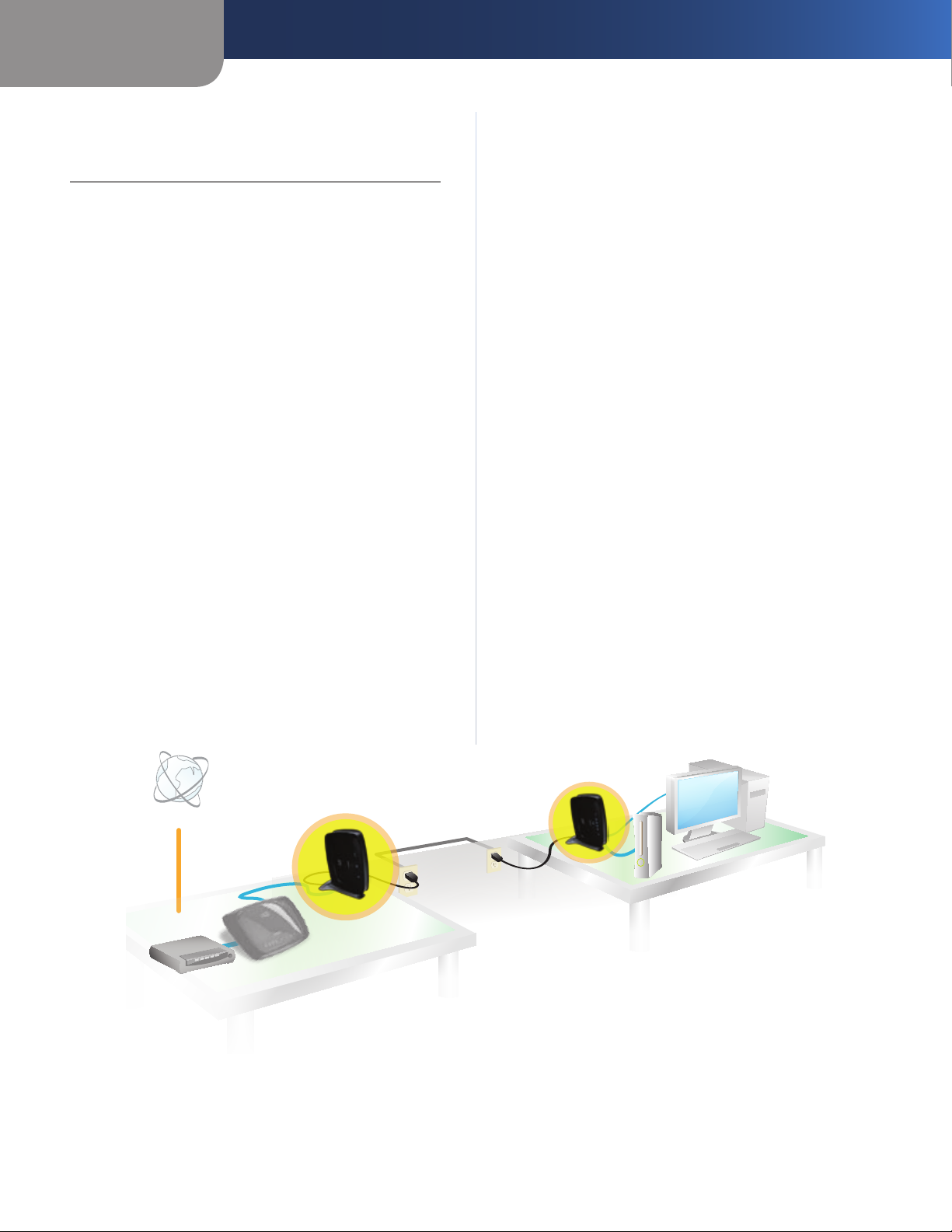
The diagram below shows the connections of a basic
powerline network. The connections between the Internet,
modem, and router stay the same.
Using an Ethernet network cable, the router is connected
to its Adapter, which is plugged into an electrical outlet.
Using Ethernet network cables, the gaming console and
computer are connected to their Powerline AV 4-Port
Network Adapter, which is plugged into an electrical
outlet.
Internet
Modem
Powerline AV Network Adapter
Router
Powerline AV
Network Adapter
Powerline
Connection Diagram of a Basic Powerline Network
Powerline AV 4-Port
Network Adapter
Gaming Console
Computer
1

Chapter 1
A Powerline Network in a Two-Story House
This diagram shows a basic powerline network in a twostory house. The router upstairs is connected to its Adapter,
which is plugged into an electrical outlet. Downstairs, the
gaming console and a computer share their Powerline
AV 4-Port Network Adapter, which is plugged into an
electrical outlet.
Using the powerlines of the home, the router expands
your local network to include the gaming console and
desktop computer in the living room. Internet access and
files can be shared between your computers and other
networked devices.
For online gaming, you can play downstairs in the comfort
of your living room, while taking advantage of your router
and high-speed Internet connection upstairs.
Introduction to Powerline Networking
Modem
Router
Powerline AV
Network Adapter
Diagram of a Powerline Network in a Two-Story House
Gaming
Console
Computer
Powerline AV
4-Port Network
Adapter
Powerline AV Network Adapter
2

Chapter 2
Product Overview
Chapter 2: Product Overview
Thank you for choosing the Linksys by Cisco powerline
products: Powerline AV Network Adapter (model number:
PLE300), Powerline AV 4-Port Network Adapter (model
number: PLS300), or Powerline AV Network Kit (model
number: PLK300).
The Powerline AV Network Adapter features one Ethernet
port to connect a router, computer, or other network
device to your powerline network, while the Powerline
AV 4-Port Network Adapter features four Ethernet ports to
connect up to four computers or other network devices to
your powerline network.
The Kit features one Powerline AV Network Adapter and
one Powerline AV 4-Port Network Adapter to create a
powerline network. Connect the Powerline AV Network
Adapter to your network router, and connect the Powerline
AV 4-Port Network Adapter to computers or other network
devices.
For more information about powerline networking, refer
to Chapter 1: Introduction to Powerline Networking,
page 1.
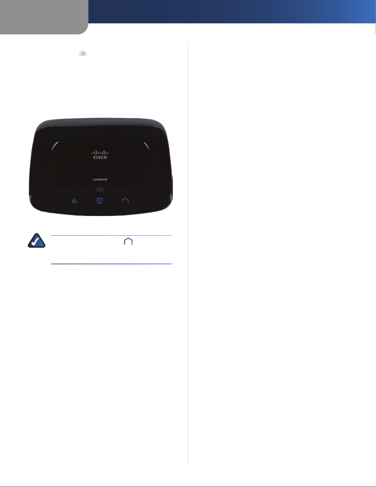
Front Panel of the Powerline AV Network Adapter (model number: PLE300)
Ethernet (Blue) The Ethernet LED lights up
when the Adapter is connected to a network
device through the Ethernet port. The LED
flashes to indicate network activity over
that port.
Powerline (Blue) The Powerline LED lights
up when the Adapter is connected to the
powerline network through the Power port. The
LED flashes to indicate network activity over
that port.
Back Panel of the Powerline AV Network Adapter (model number: PLE300)
Ethernet The Ethernet port connects to an
Ethernet network device, such as a router or
computer.
Reset To restore the factory default settings
(including the advanced security setting,
Network Password), press and hold the Reset
button for three seconds.
Power The Power port connects to the
powerline end of the power cord.
HomePlug Simple Connect Button Use the
HomePlug Simple Connect button to configure
advanced security (the Network Password) for
your powerline network. For instructions, refer
to Chapter 3: Advanced Security, page 6.
Power (Blue) The power LED lights up when
the Adapter is powered on.
Powerline AV Network Adapter
Front Panel of the Powerline AV 4-Port Network Adapter (model number: PLS300)
3
Chapter 2
HomePlug Simple Connect Button Use the
HomePlug Simple Connect button to configure
advanced security for your powerline network.
For instructions, refer to Chapter 3: Advanced
Security, page 6.
Power (Blue) The power LED lights up when
the Adapter is powered on.
Ethernet (Blue) These numbered LEDs
correspond with the numbered Ethernet ports
on the back panel. A LED lights up when its
corresponding port is connected to a network
device. It flashes to indicate network activity
over that port.
Powerline (Blue) The Powerline LED lights
up when the Adapter is connected to the
powerline network through the Power port. The
LED flashes to indicate network activity over
that port.
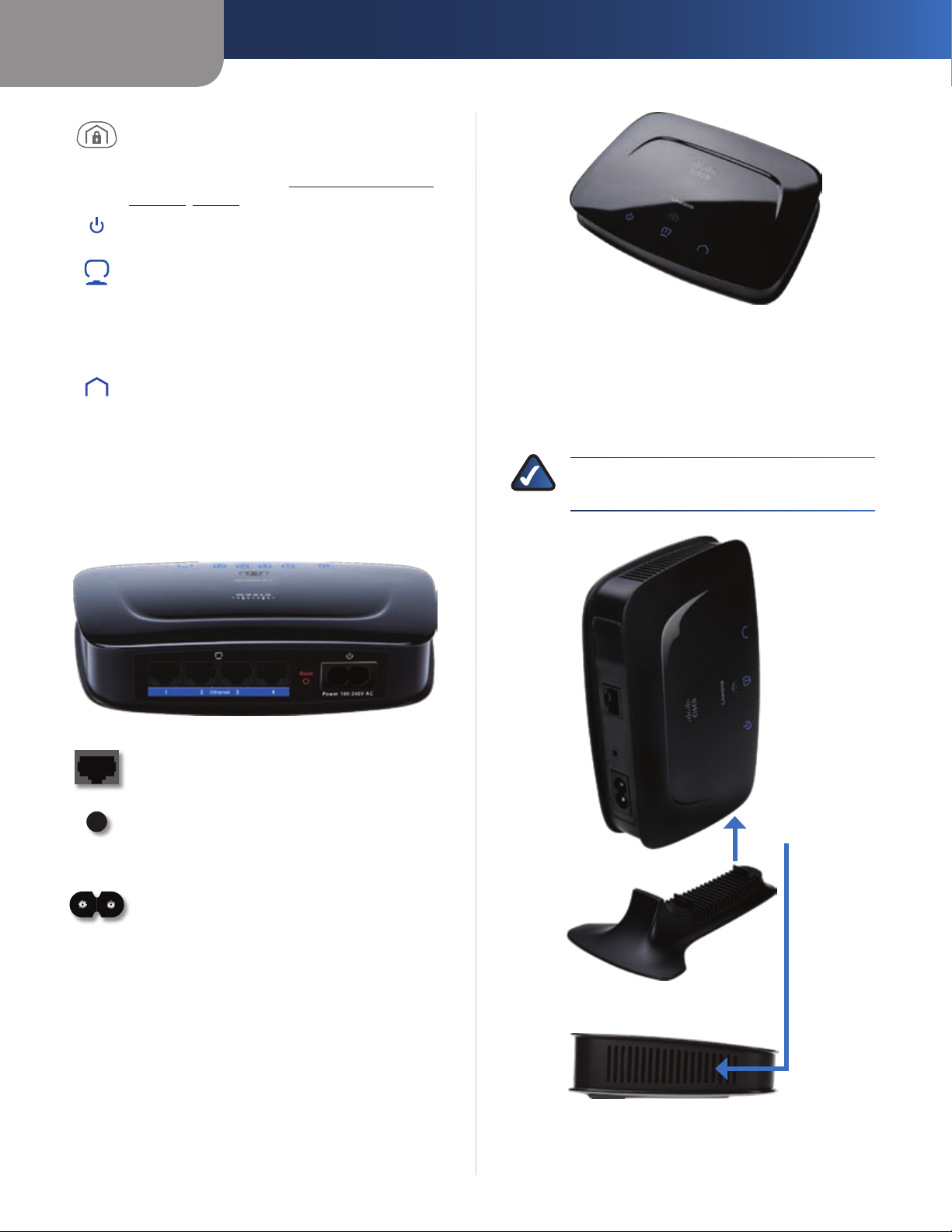
Back Panel of the Powerline AV 4-Port
Product Overview
Vertical Placement
The stand fits only on the side panel adjacent to the Power
port.
Insert the stand into the side panel until it snaps into 1.
place.
NOTE: When the Adapter is on the stand, the
Power port is closest to the stand.
Network Adapter (model number: PLS300)
Ethernet 1-4 These Ethernet ports (1, 2, 3,
4) connect to computers or other network
devices.
Reset To restore the factory default settings
(including the advanced security setting,
Network Password), press and hold the Reset
button for three seconds.
Power The Power port connects to the
powerline end of the power cord.
Placement Options
Fourth Slot of
Side Panel
There are three ways to place the Adapter. The first way
is horizontal placement on a surface. The second way
is vertical placement on a stand. The third way is wallmounting.
Horizontal Placement
Place the Adapter on a level surface near an electrical
outlet.
Powerline AV Network Adapter
Insert Stand into Side Panel
Place the Adapter on a level surface near an electrical 2.
outlet.
4
Chapter 2
60 mm
Product Overview
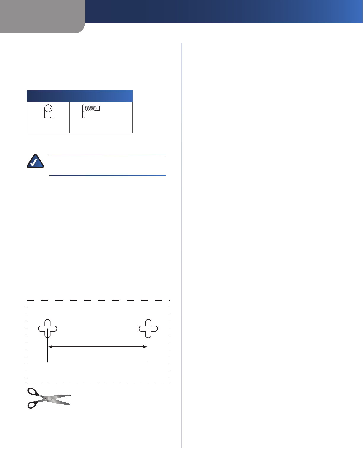
Wall-Mounting Placement
The Adapter has four wall-mount slots on its back panel.
The distance between two adjacent slots is 60 mm
(2.36 inches).
Two screws are needed to mount the Adapter.
Suggested Mounting Hardware
4 mm 1-1.5 mm
Note: Mounting hardware illustrations are not †
true to scale.
NOTE: Linksys is not responsible for damages
incurred by insecure wall-mounting hardware.
Follow these instructions:
Determine where you want to mount the Adapter. 1.
Make sure that the wall you use is smooth, flat, dry,
and sturdy. Also make sure the location is within reach
of an electrical outlet.
Drill two holes into the wall. Make sure the holes are 2.
60 mm (2.36 inches) apart.
Insert a screw into each hole and leave 3 mm 3.
(0.12 inches) of its head exposed.
Maneuver the Adapter so the two wall-mount slots 4.
line up with the two screws.
Place the wall-mount slots over the screws and slide 5.
the Adapter down until the screws fit snugly into the
wall-mount slots.
2-2.5 mm
should be 60 mm. Then place the template on the wall to
drill precise spacing.
Wall Mounting Template
Print this page at 100% size, and cut along the dotted line.
Check the template’s accuracy by measuring the distance
between the wall-mount slots with a ruler. This distance
Powerline AV Network Adapter
5

Chapter 3
Advanced Security
Chapter 3: Advanced Security
Overview
Before you begin, you should have a powerline network
already installed; the Powerline AV Network Adapters are
connected and powered on.
The following instructions describe how to configure
advanced security for three Adapters (Adapters 1, 2, and
3). The HomePlug Simple Connect button is located
on the top panel of each Adapter. You will use this button
on the Adapters to set up a new Network Password for the
powerline network.
NOTE: The devices connected to the Powerline
AV Network Adapters will temporarily lose
Internet connection during the security setup.
Security for First Two Adapters
(If the Power LED does not start flashing, try again;
press and hold the HomePlug Simple Connect button
for two seconds.)
After the Network Password is configured, 5.
Adapters 1 and 2 will restart. On each Adapter, the
Power and Powerline LEDs light up.
(If the Powerline LEDs do not light up, try again; repeat
steps 1-4.)
In this section, configure a new Network Password for two
Adapters.
On Adapter 1, press and hold the HomePlug Simple 1.
Connect button for at least ten seconds. Release
the button when the Power LED starts flashing and
Adapter 1 restarts.
NOTE: Holding the HomePlug Simple Connect
button for at least ten seconds prepares the
Adapter for security setup.
On Adapter 2, press and hold the HomePlug Simple 2.
Connect button
the button when the Power LED starts flashing and the
Adapter restarts.
For Adapter 1, wait for the Power LED to become 3.
solidly lit. Press and hold the HomePlug Simple
Connect button for two seconds. Then release
the button. The Power LED starts flashing.
(If the Power LED does not start flashing, try again;
press and hold the HomePlug Simple Connect button
for two seconds.)
NOTE: Holding the HomePlug Simple Connect
button for two seconds shares the new Network
Password between the two Adapters.
On Adapter 2, press and hold the HomePlug Simple 4.
Connect button
the button. The Power LED starts flashing.
for at least ten seconds. Release
for two seconds. Then release
Power, Ethernet, and Powerline LEDs are Lit
NOTE: The devices connected to the Adapters
will regain Internet connection within five
minutes.
Congratulations! Security has been configured for the
first two Powerline AV Adapters.
Security for Additional Adapter
In this section, configure a new Network Password for
Adapter 3.
On Adapter 3, press and hold the HomePlug Simple 1.
Connect button for at least ten seconds. Release
the button when the Power LED starts flashing and
Adapter 3 restarts.
NOTE: Do not press the HomePlug
Simple Connect button on any Adapter
that already has the new Network
Password configured, including Adapter 1
and 2.
For Adapter 3, wait for the Power LED to become solidly 2.
lit. Press and hold the HomePlug Simple Connect
button for two seconds. Then release the button.
The Power LED starts flashing.
Powerline AV Network Adapter
6
Chapter 3
On Adapter 1 or 2, press and hold the HomePlug Simple 3.
Connect button for two seconds. Then release the
button. The Power LED starts flashing.
After the Network Password is configured, Adapter 3 4.
will restart, and the Power and Powerline LEDs
light up.
(If the Powerline LEDs do not light up, try again; repeat
steps 1-3.)
Advanced Security
Power, Ethernet, and Powerline LEDs are Lit
NOTE: The Powerline LED indicates that
the connection between Adapter 3 and your
powerline network has been established.
Repeat steps 1-4 to add additional Adapters, one at a 5.
time.
Congratulations! Security has been configured for the
additional Powerline AV Adapter(s).
Powerline AV Network Adapter
7
 Loading...