

Linksys NSS4000 Series, NSS6000 Series Administrator's Manual
Linksys Business Series Network Storage System
Administrator Guide
Linksys Business Series Network Storage System
Models NSS4000 and NSS6000 Series
ADMINISTRATOR GUIDE

© 2007 Copyright 2007, Cisco Systems, Inc.
Specifications are subject to change without notice.
Linksys, the Cisco Systems logo, the Linksys Logo, and the Linksys One logo are registered trademarks of Cisco
Systems, Inc. All other trademarks mentioned in this document are the property of their respective owners.

Contents
Network Storage System (NSS) Administrator Guide
Chapter 1: Introduction . . . . . . . . . . . . . . . . . . 4
Using the Help 5
Recommended Disk Drive List 6
Chapter 2: Working with the System . . . . . . . . . . . . . 7
Viewing the Hardware Monitor 11
Viewing and Managing the System Logs 12
Configuring the System for UPS Support 14
NSS-supported UPS Product Families 15
Chapter 3: Managing the Network Options . . . . . . . . . . . 16
Viewing the Network Settings 18
Configuring the Network Link IP 19
Resetting the DHCP Lease on a Link 20
Viewing VLANs Configured on the NSS 21
Allowing a VLAN Access to the NSS 22
Changing a VLAN Configuration 25
Removing a VLAN’s Access to the NSS 26
Configuring the NSS Network Identification 27
Configuring DNS or WINS for Name Resolution 29
Joining the NSS to a Network Information System (NIS) Domain 31
Editing Access Control Lists (ACLs) from Windows Explorer: Restrictions 33
Running Diagnostics of your Physical Links 34
Configuring the Network Ports 35
Setting up the Link Bonding & Advertising Modes 36
Chapter 4: Managing your Storage . . . . . . . . . . . . . . 38
Choosing a RAID Array Level 42
Creating a RAID Array 44
Adding a Disk Drive to an Array 45
Deleting an Array 47
Migrating a RAID Array to another Storage Device 48
Virtualizing Storage within your Network 49
Exporting Storage to your Network 50
Creating Virtualized Storage 51
Unexporting Storage 52
Volume Management 53
Creating a Volume 54
Expanding a Volume 56
Deleting a Volume 58
Viewing the Snapshot Reserve Details 59
Creating a Snapshot for a Volume 61
Taking a Manual Snapshot of a Volume 63
1

Contents
Network Storage System (NSS) Administrator Guide
Windows End Users: Accessing a Snapshot for a Share 64
Volume Encryption Overview 65
Locking an Encrypted Volume 66
Unlocking a Locked Volume 67
Changing the Password for an Encrypted Volume 69
Storage Options 71
Setting the RAID Rebuild Priority 72
Setting the Spin Down Time 73
Chapter 5: Administering Access to the NSS. . . . . . . . . . . 74
Managing your NSS Users 75
Creating a User Profile 76
Editing a User Profile 78
Integrating Users from an ADS, NTv4, or NIS Domain 80
Deleting a User Profile 81
Working with Groups 82
Creating a Group 83
Changing the Users Assigned to a Group 85
Integrating Groups from an Active Directory, NTv4, or NIS Domain 86
Deleting a Group 87
Managing Volume Quotas 89
Creating Volume Quota for a User or Group 91
Setting up the Grace Period for a Volume Quota 93
Changing a Volume Quota for a User or Group 94
Clearing a Quota 95
Network Filters Overview 96
Defining the Default Network Policy 97
Creating a Network Filter 98
Available Access Filters 100
Deleting a Network Filter 102
Configuring the User/Group Settings 103
Chapter 6: Managing the Shares. . . . . . . . . . . . . . 104
Creating a Share 105
Editing an Existing Share 108
Adding a DFS Shared Folder 110
Restrictions using Microsoft DFS from the NSS 112
Setting up CIFS Access 113
Setting up Network Filesystem (NFS) Access 114
Configuring the NSS for FTP Access 115
Creating or Running a Backup of a Share 117
Creating a Scheduled Backup for a Share 118
Initiating a Backup for a Share 120
2

Contents
Network Storage System (NSS) Administrator Guide
Deleting Backup Images 122
Chapter 7: Managing the Admininstrator Options . . . . . . . 123
Rebooting or Shutting Down the NSS 124
Upgrading the NSS Firmware 126
Restoring the Factory Default Configuration 127
Managing the NSS Configuration 129
Saving the Current Configuration 130
Restoring a Configuration File 132
Deleting a Configuration File 134
Configuring the Timing Settings 135
Configuring SNMP Alerts 137
Changing the Administrator Password 139
Chapter 8: Accessing the NSS’s Storage . . . . . . . . . . . 140
Logging into the CIFS Shares with Administrator Privileges 141
Windows Users: Accessing the NSS Storage using CIFS/SMB 142
Windows Users: Accessing the NSS Storage through FTP 143
Mac Users: Accessing Storage through CIFS/SMB 144
Mac Users: Accessing Storage through FTP 145
UNIX/Linux Users: Accessing Storage through NFS 146
UNIX/Linux Users: Accessing Storage through FTP 147
Chapter 9: Glossary . . . . . . . . . . . . . . . . . . 148
Chapter 10: Troubleshooting . . . . . . . . . . . . . . . 157
LEDs & Buttons 157
Repairing a Degraded Array 160
Working with a Failed Array 162
Free Bound Aggregation Storage when the Master System Fails 163
All CIFS Connections were Unexpectedly Ended 164
Hotplugging the Ethernet Link doesn’t Reset IP or Link Rate 165
Unable to Create a Share or Quota for a Volume 166
Cannot access the NSS through FTP 167
Configuration Page does not Appear in Internet Explorer 168
Handling an Unexpected (Unclean) Shutdown 170
Appendix A: Support Contact Information . . . . . . . . . . 171
3

Chapter
Network Storage System (NSS) Administrator Guide
Introduction
Thank you for choosing the Linksys Business Series Network Storage System (NSS).
Administering a network can be a difficult job. Finding low-cost ways to simplify your datamanagement tasks means that you have more resources to dedicate elsewhere. The NSS is a
Network Attached Storage (NAS) unit that appears as a native file server for the various clients
within your network, including Windows, Apple Macintosh, UNIX, and Linux platforms. The biggest
benefit to your users is that they can now access data that might be stored across different physical
platforms as simply as if it were on their own computers. The NSS provides a single repository that
is completely dedicated to storage, ensuring the integrity, reliability, and accessibility of your data
for a relatively low cost.
The NSS lets you install up to four physical disk drives as well as virtualize your storage into one or
more logical, redundant storage units or RAID arrays. The NSS uses the most common file-based
protocols such as NFS, CIFS, and FTP for file sharing.
Benefits
1
The NSS offers the following main advantages to your business:
• Cross-platform File Sharing: Share files easily and inexpensively across heterogeneous
platforms over a cost-effective Ethernet and IP network.
• Easy Installation and Administration: With a basic understanding of networking, the NSS is
easy to get going and to maintain.
• Data Consolidation: Centralize data to reduce management costs and maximize your
investment in existing hardware. This also means better data security.
Chapter 1: Introduction
4
Chapter
Network Storage System (NSS) Administrator Guide
Using the Help
The NSS (Network Storage System) help file provides information about using the configuration
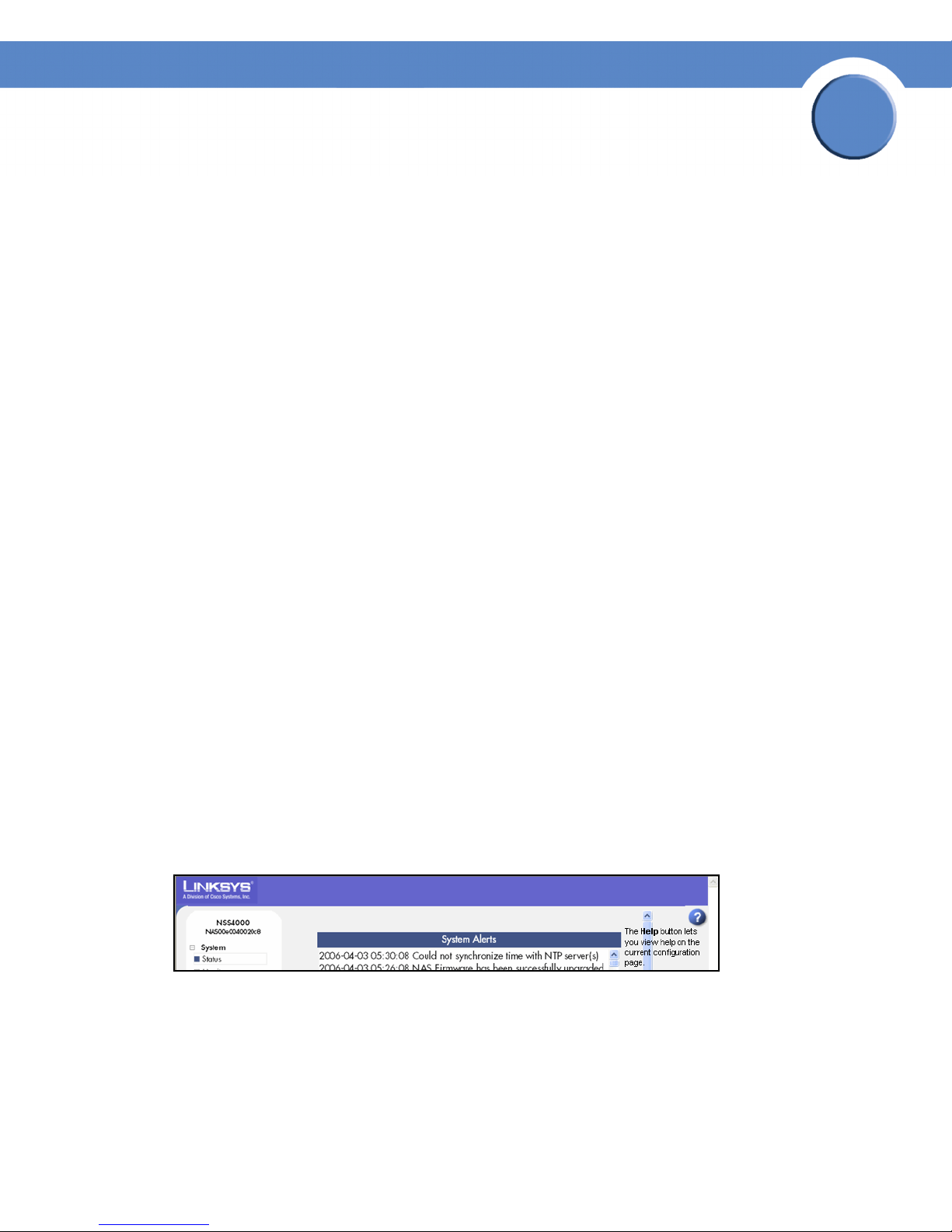
interface to configure the NSS. You can access the help topics either through the Help link found in
the Manager Menu or by clicking the Help button at the top-right corner of each configuration
page.
Audience
The information contained in these help pages is intended for use by network administrators. It
assumes a basic understanding of storage-related concepts, including RAID, filesystems, and
networking.
About the NSS Configuration Interface
The NSS configuration interface contains some basic navigation features to help you as you
configure the NSS.
• Manager Menu: The Manager Menu forms the left side of the configuration interface
window. It contains the menu options that represent the major configuration areas for the
NSS. For example, System, Network, Share, Storage, and so on. When you click an option,
a sub-menu of related options appears. Clicking a subtopic opens the associated topic in the
Top ic page in the right side of the window.
1
• Topi c Pa ge: When you select a topic from the Manager Menu, the configuration page for
that topic appears in the right side of the window.
Getting Help
There are two buttons on the NSS configuration interface window that you can click to access help:
•From the Manager Menu click Help to display the full online Administrator Guide. Use the
navigation tools within the help to find information for your chosen topic.
• A context-sensitive help button appears in the upper-right corner of the topic page. Click it to
display help on the specific configuration area. For example, if the current configuration topic
is about the status of your disk drives, click the Help button for information about the details
that appear on the status page.
Chapter 1: Introduction
Using the Help
5

Chapter
Network Storage System (NSS) Administrator Guide
Recommended Disk Drive List
If you are purchasing disk drives to install in the NSS, please refer to the product support
information offered on the LinksysOne website for a list of recommended disk drives.
The decision of which disks to purchase also needs to be made based on the RAID levels you want to
create. For example, if you are creating a RAID (versus a JBOD), make sure that each of the disks
used in the array have the same disk capacity. The RAID is built using the capacity of the smallest
disk in the array.
1
Chapter 1: Introduction
Recommended Disk Drive List
6
Chapter
Network Storage System (NSS) Administrator Guide
Working with the System
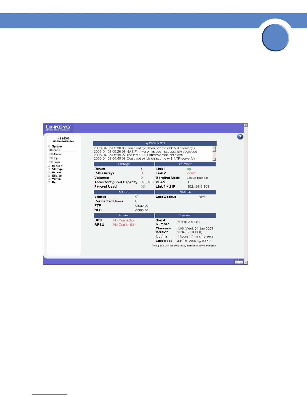
The System Status page provides an overview of the current operating condition of the NSS. For
example, you can view system alert messages such as if a disk drive is failing or has failed, if a
volume is approaching its full capacity, if an array rebuild is complete, and so on. You can also view
the current status of any of the following: storage, shares, backups, volume snapshots, network,
power, and system details. Status pages like the System Status page automatically refresh on a
regular interval and are very helpful for monitoring the progress of certain processes such as
building a RAID.
2
The following sections provide a detailed explanation of the information that appears on the System
Status page.
System Alerts
The System Alerts section shows any system messages issued since the last time they were cleared.
Messages can range in severity from informational to immediate action required.
There are three type of alerts that can appear in this area of the System Status page:
• Error: These types of messages indicate the most severe problem with the NSS. They are
color-coded red and require immediate action. For example, if a disk drive or RAID array is
in a failed condition.
Chapter 2: System
7

Chapter
Network Storage System (NSS) Administrator Guide
• Warning: These types of messages indicate there is a problem with the NSS that requires
eventual action. They are color-coded orange. For example, if the amount of storage used for
a volume is over 90%.
• Notification: These types of messages are simply to advise of changes to the NSS. They do
not require action and are color-coded green. For example, the RAID rebuild is complete.
Storage Status
The Storage area displays details about the configured storage on the NSS, including:
• Drives: The number of physical disk drives installed.
• RAID Arrays: The number of configured RAID Arrays.
• Volumes: The number of configured volumes.
• Total Configured Capacity: The total aggregate size of all configured volumes.
• Percent Used: The total amount of the configured capacity used. The percentage is colorcoded according to the current percentage used:
2
- Green: 0 to 74%
- Orange: 75-89%
- Red: 90-100%
Network Status
The Network area displays the following:
• Link 1 & 2: The current status of the physical links. The status of the link can be up (colorcoded green) or down (color-coded red). If the link is not present, the status appears as
"down".
• Bonding Mode: Displays how the bonding mode for the physical links has been configured
on the Network Properties page. (see Setting up the Link Bonding & Advertising Modes)
• VLANs: The number of VLANs configured on the NSS.
• Link 1 IP: The IP address of the first Ethernet link.
• Link 2 IP: The IP address of the second Ethernet link (if installed). If the bonding mode is set to
"active backup" or "802.3ad", the two links appear as a single entity (i.e., "Link 1+2 IP").
Shares Status
The Shares area displays the status of the following:
• Shares: The number of configured shares.
• Connected Users: The total number of user sessions currently connected to the NSS.
Chapter 2: System
8

Chapter
Network Storage System (NSS) Administrator Guide
• FTP: FTP access state (enabled or disabled).
• NFS: NFS access state (enabled or disabled).
Backup/Snapshots Status
The Backup/Snapshots area displays the following:
• Snapshots: The total number of volume snapshots configured.
• Last Backup: The date and time of the last backup run. If a backup has never been run on the
system, the word "never" appears.
Power Status
The Power area displays the following:
• UPS: The following options are available depending on the current operating condition of the
UPS. For more information about the functioning of the UPS, refer to the UPS documentation.
2
- No Connection: A UPS is not currently connected to the NSS.
- On Mains: A UPS is connected to the NSS but is not currently being used to power the unit.
The NSS is deriving power from the mains power.
- On Battery (%): The NSS is currently deriving its power from the UPS battery. The
percentage of power still available is also listed and is color-coded according to the amount
of battery remaining.
• RPSU: The following options are available depending on the current operating condition of
the RPSU. For more information about the functioning of the RPSU, refer to the RPSU
documentation.
- No Connection: There is no RPSU installed.
- Ready: An RPSU is installed and is currently available as a backup power source.
- Standby/Fault: An RPSU is installed but is in Standby mode, or, the RPSU is installed and
has some sort of fault condition. For example, the RPSU is connected to the NSS but is
powered off.
- Active: The RPSU is currently being used to provide backup power to the NSS.
- Unavailable: The RPSU is currently providing backup power to another device and is not
available to provide backup power to the NSS.
System Status
The System area displays the following:
• Serial Number: The serial number of the NSS.
• Firmware Version: The current version and date of the firmware installed on the NSS.
Chapter 2: System
9

Network Storage System (NSS) Administrator Guide
• Uptime: The number of days the NSS has been running since it was last rebooted.
• Last Boot: The date when the NSS was last rebooted.
Chapter
2
Chapter 2: System
10
Chapter
Network Storage System (NSS) Administrator Guide
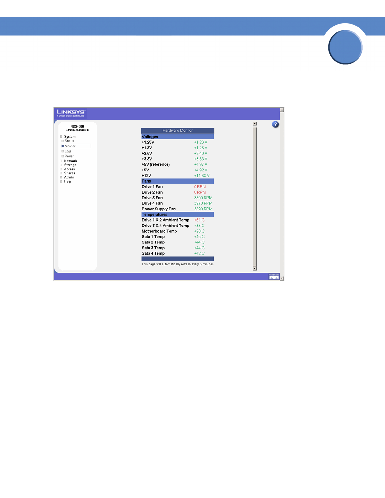
Viewing the Hardware Monitor
The Hardware Monitor page displays details about the following physical conditions related to the
NSS:
2
• Voltages : The current voltage reading for all voltage rails in the system. The reading is colorcoded depending on whether the voltage level is within specification (green) or out of
specification and in need of attention (red).
• Fans: The fan speed for each chassis fan. If the fan has stalled, the reading is color-coded
red. Normal fan operation is color-coded green.
• Tem pe rat ur es: The NSS has temperature sensors located at various parts of the chassis.
Temperature readings are done from these sensors as well as from any installed disks
(provided that the disk has an internal temperature sensor). If a disk does not have a
temperature sensor, the reading appears as "unavailable". If the temperature of the system or
disks is over or under the ideal temperature, the temperature is color-coded red. When the
temperature is within the normal range the color-coding is green.
Chapter 2: System
Viewing the Hardware Monitor
11
Chapter
Network Storage System (NSS) Administrator Guide
Viewing and Managing the System Logs
The NSS captures various types of information into log files, such as user access details. The logs can
be stored locally or sent to a remote server on the network. Since local space allocated for log files is
limited, the logs are overwritten once the space is filled. Each new event overwrites the oldest event
recorded in the file.
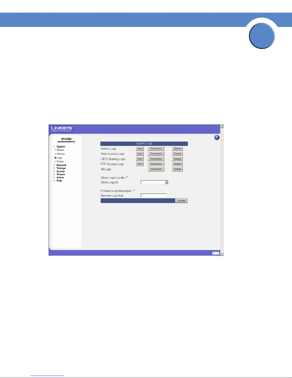
To work with the log files:
1. From the Manager Menu, click System Logs.
The System Logs page appears.
2
2. You can view, download, or delete any of the following types of log files:
• Admin: A full list of time-stamped actions that were initiated through the NSS configuration
interface.
• Web Access: This log displays IP addresses of the systems that accessed the NSS
configuration interface and the date and time of the authentication requests. This information
helps you detect unauthorized attempts to access the NSS configuration interface.
• CIFS Sharing: A time-stamped event log of events initiated by users accessing shares through
CIFS.
• FTP Access: A time-stamped log of FTP actions, including user logins, file transfers, and user
logouts.
Chapter 2: System
Viewing and Managing the System Logs
12
Chapter
Network Storage System (NSS) Administrator Guide
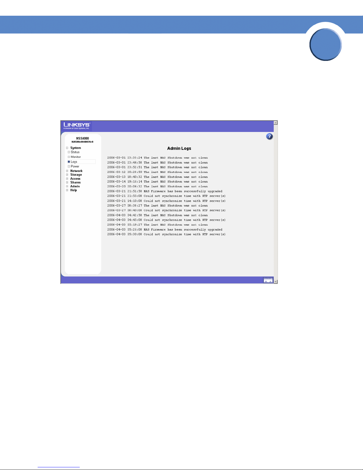
• All Logs: A concatenation of all the log files. You can download and save this file to a
location on your network as required.
• Diagnostics: A time-stamped log of the cable diagnostic tests run. You can download and
save this file.
The following screenshot is an example of the Administrator Log:
2
3. Choose where you want to store the log files:
• Locally: To store the log files on the NSS, select Store Logs Locally, and then select the volume
to which you want to store the logs from the options in the Store Logs to drop-down menu.
• Remotely: To store the log files on a remote server, select Forward Log Messages, and then
enter the name or IP address of the server in the Remote Log Host field. Note that the remote
server must be running a syslog server.
4. Click Update.
Chapter 2: System
Viewing and Managing the System Logs
13
Chapter
Network Storage System (NSS) Administrator Guide
Configuring the System for UPS Support
You can set up the NSS to use an uninterruptible power supply (UPS) if one is connected directly to
the UPS port on the NSS.
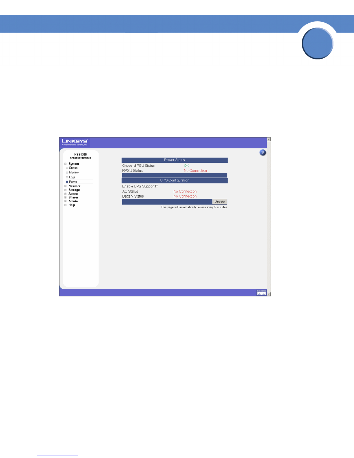
To set up the UPS:
1. From the Manager Menu, click System Power.
The System Power page appears.
2
2. To enable UPS support, select Enable UPS support.
3. Click Update.
Chapter 2: System
Configuring the System for UPS Support
14

Network Storage System (NSS) Administrator Guide
NSS-supported UPS Product Families
The NSS supports the following UPS product families:
• APC Back-UPS Pro USB
• APC Back-UPS RS USB
•APC Back-UPS USB
• APC Back-UPS LS USB
• APC Back-UPS ES/CyberFort 350
• APC Smart-UPS USB
Chapter
2
Chapter 2: System
NSS-supported UPS Product Families
15
Chapter
Network Storage System (NSS) Administrator Guide
Managing the Network Options
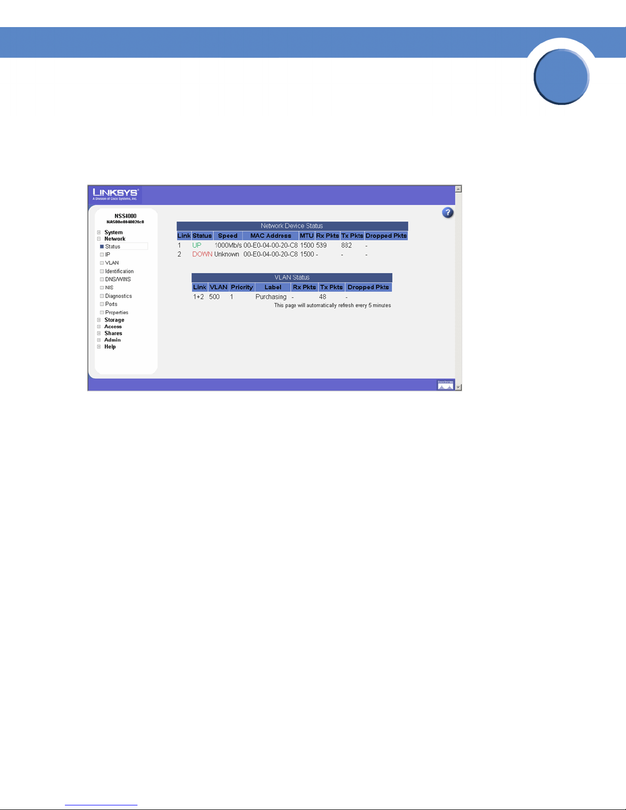
The Network Device Settings page displays the current status of the NSS’s physical and virtual
network interfaces.
3
Physical Interfaces
The Network Device Status table displays the current status of the physical Ethernet links connected
to the NSS.
• Link: The number that appears in this column identifies the link attached to the NSS. It can be
either 1 or 2.
• Status: The status of the physical link. Options include:
- Up: The link is up (color-coded green) and operational.
- Down: The link is down (color-coded red) and not operational. If a cable is actually
connected to the Ethernet port, check the cable integrity and the status of the device (switch,
router, or computer) at the other end of the cable. You can use the NSS’s cable diagnostic
feature (see Running Diagnostics of your Physical Links) to assist you.
• Speed: The configured speed, in Mbps, of the physical link. Options include: 10 Mbps, 100
Mbps, 1000 Mbps.
• MAC Address: The Ethernet MAC address for the link.
• MTU: The Maximum Transmission Unit (MTU) in bytes defined for the link. This is set either
manually from the Network Properties page or set via the DHCP server.
• Rx Pkts: The total number of IP packets received since the last boot.
• Tx Pkts: The total number of IP packets transmitted since the last boot.
Chapter 3: Network
16

Chapter
Network Storage System (NSS) Administrator Guide
• Dropped Pkts: The total number of IP packets dropped since the last boot.
Virtual Interfaces
The VLAN Status area of the Network Status page displays the current status and details regarding
each configured VLAN.
• Link: The number that appears in this column identifies the physical link on which the VLAN is
configured. If there are two physical links, the link appears as either "1" or "2", or, if the two
links are bonded, the number appears as "1+2".
• VLAN: The VLAN number.
• Priority: The 802.1p priority set for the VLAN. Options include 0 through 7 (0 being best
effort data and 7 being network critical data).
• Label: The text description defined for the VLAN.
• Rx Pkts: The total number of IP packets received on the VLAN interface since the last boot.
3
• Tx Pkts: The total number of IP packets transmitted on the VLAN interface since the last boot.
• Dropped Pkts: The total number of IP packets dropped on the VLAN interface since the last
boot.
Chapter 3: Network
17
Chapter
Network Storage System (NSS) Administrator Guide
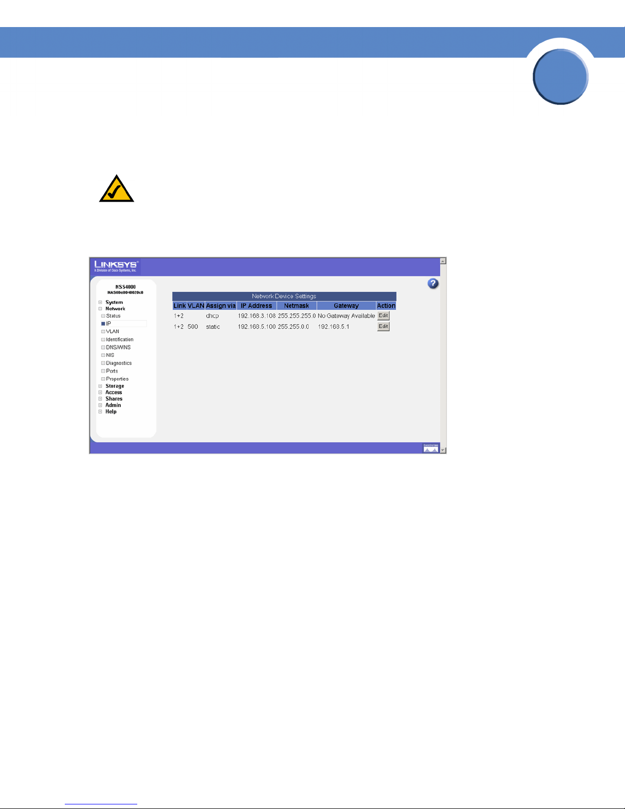
Viewing the Network Settings
The Network Device Settings page displays information about the physical and virtual interfaces
currently configured on the NSS.
NOTE: If you hotplug the Ethernet link after the initial installation of the NSS, wait 15
seconds between the time you unplug the cable and then plug it back in. The NSS
displays the correct new settings within 10 seconds.
3
To dis pla y the Network Device Settings page, from the Manager Menu, click Network IP. The
Network Device Settings table displays the following:
• Link: "1+ 2" appears in this column.
• VLAN: The ID assigned to the virtual interface. For a physical interface, this column is blank.
• Assign Via: The method used to assign an IP configuration to the physical or virtual interface.
Options include:
- DHCP: The IP configuration was assigned by the DHCP server.
- Manual: A static IP configuration was manually entered through the NSS.
- AutoIP: The interface was configured to use DHCP for IP configuration but no DHCP server
was found. Instead the IP address was assigned by the AutoIP protocol.
• IP Address: The IP address for the physical or virtual interface.
• Netmask: The netmask for the physical or virtual interface.
• Gateway: The address of the gateway for the physical or virtual interface.
Chapter 3: Network
Viewing the Network Settings
18
Chapter
Network Storage System (NSS) Administrator Guide
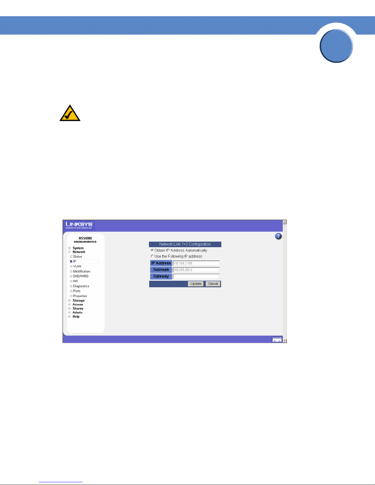
Configuring the Network Link IP
You need to configure the method for assigning an IP configuration to each physical and virtual
interface connected to the NSS.
NOTE: If you hotplug the Ethernet link after the initial installation of the NSS, make sure you
wait 15 seconds between the time you unplug the cable and then plug it back in. The
NSS displays the correct new settings within 10 seconds.
To set the IP address allocation method for an interface:
1. From the Manager Menu, click Network IP.
The Network IP page appears listing each physical and virtual interface.
2. Click Edit on the row of the interface you want to configure.
3
The Network Link Configuration page appears.
3. Select one of the following:
• Obtain IP Address Automatically: Use a DHCP server to retrieve the IP address, netmask,
and gateway address for the interface.
• Use the Following IP Address: Enter the IP configuration details manually, in dotted-quad
notation.
4. Click Update.
Chapter 3: Network
Configuring the Network Link IP
19
Chapter
Network Storage System (NSS) Administrator Guide
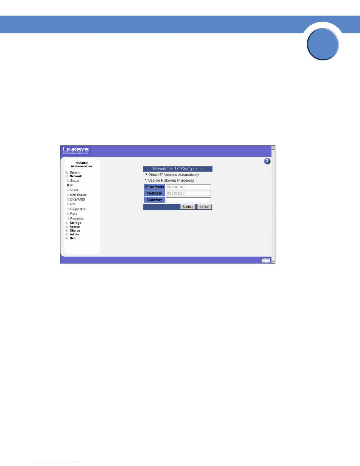
Resetting the DHCP Lease on a Link
You can force a renewal of the DHCP lease on a physical link or VLAN that is configured for DHCP:
1. From the Manager Menu, click Network IP.
The Network IP page appears listing each physical and virtual interface.
2. Click Edit on the row of the link IP you want to reset.
The Network Link Configuration page appears.
3
3. Click Update.
Chapter 3: Network
Resetting the DHCP Lease on a Link
20
Chapter
Network Storage System (NSS) Administrator Guide
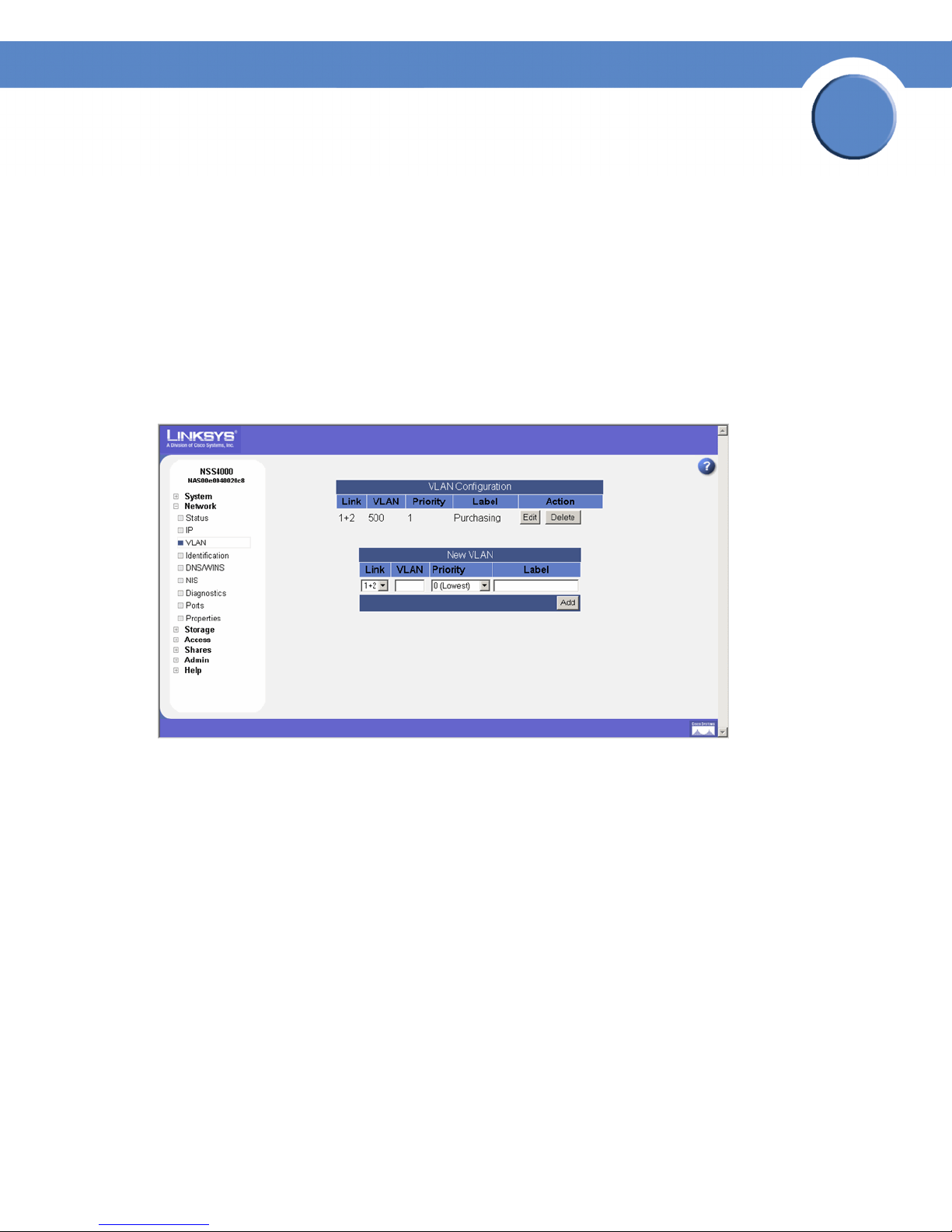
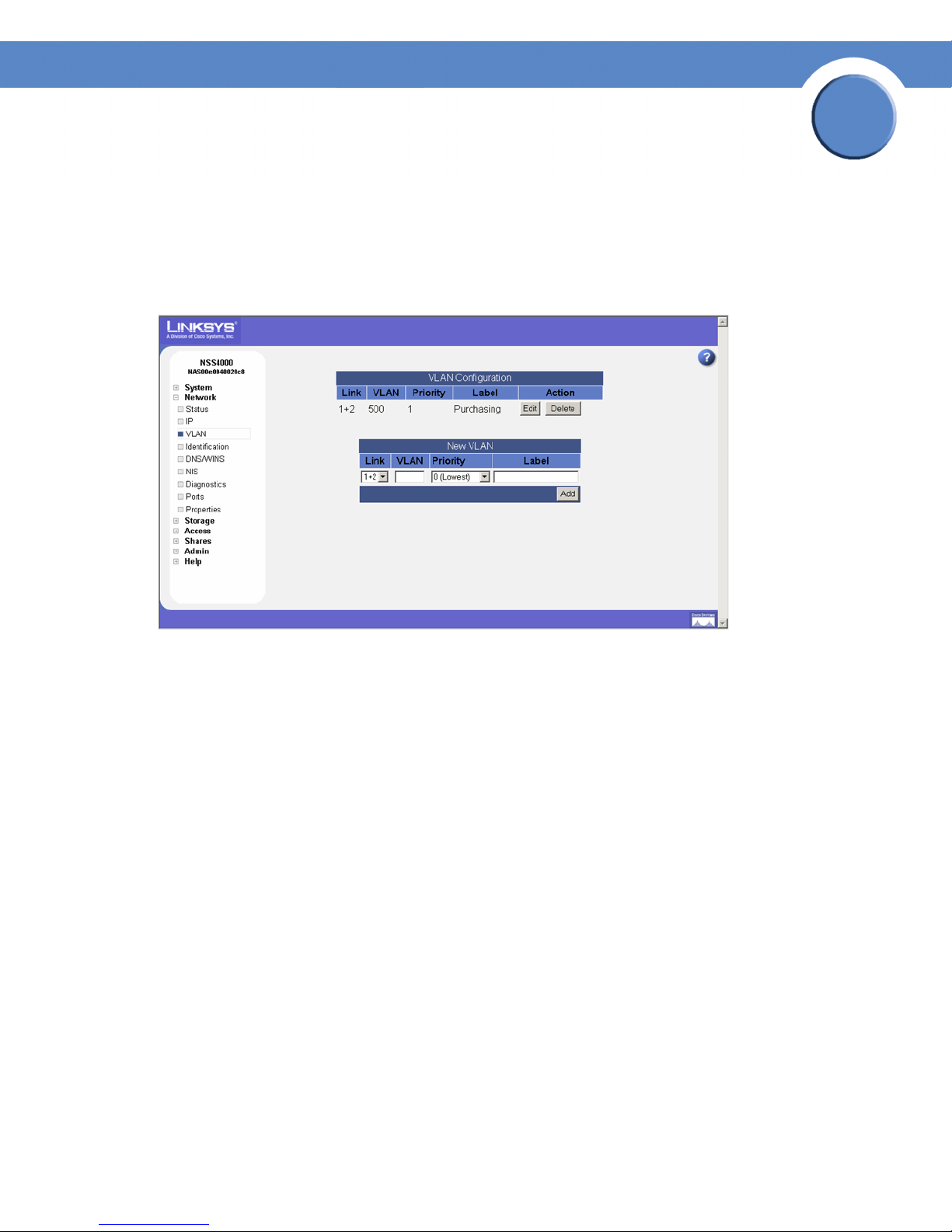
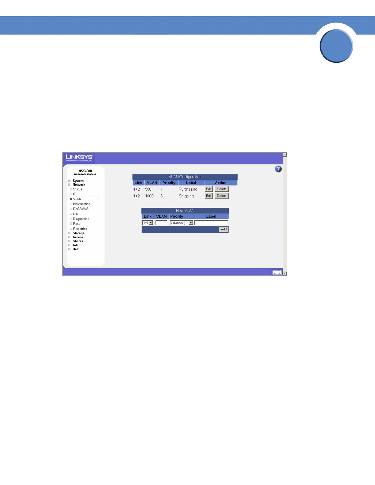
Viewing VLANs Configured on the NSS
When you first display the Network VLAN page, the currently configured VLANs appear.
Configuring a VLAN to connect to the NSS depends if it is trunk-based or port-based. To configure a
trunk-based VLAN, follow the steps provided next. To configure a port-based VLAN, configure the
switch to assign the port to which the NSS is connected to the desired VLAN. In this case, no
configuration changes are required on the NSS.
To view the VLANs currently configured on the NSS:
1. From the Manager Menu, click Network VLAN.
The VLAN Configuration page appears.
3
2. View the following details for each existing VLAN that appears in the VLAN Configuration
table:
• Link: The link on which the VLAN is configured. The status appears as "1+2".
• VLAN: The ID of the VLAN. This is configured when the VLAN is added to the NSS and
should match the ID of the VLAN as it is configured in your network. The range of valid VLAN
IDs is from 0 to 4095.
• Priority: The quality of service (QoS) as defined in the IEEE 802.1p standard for the VLAN
traffic. VLAN Ethernet frames contain a three-bit priority tag ranging from 0 to 7 (where 0 is
best effort and 7 is network-critical traffic).
• Label: A text description for the VLAN (for example, "Data," "Voice," "Video," and so on).
This description is used solely as a reference within the NSS interface and does not affect its
operation.
Chapter 3: Network
Viewing VLANs Configured on the NSS
21
Network Storage System (NSS) Administrator Guide
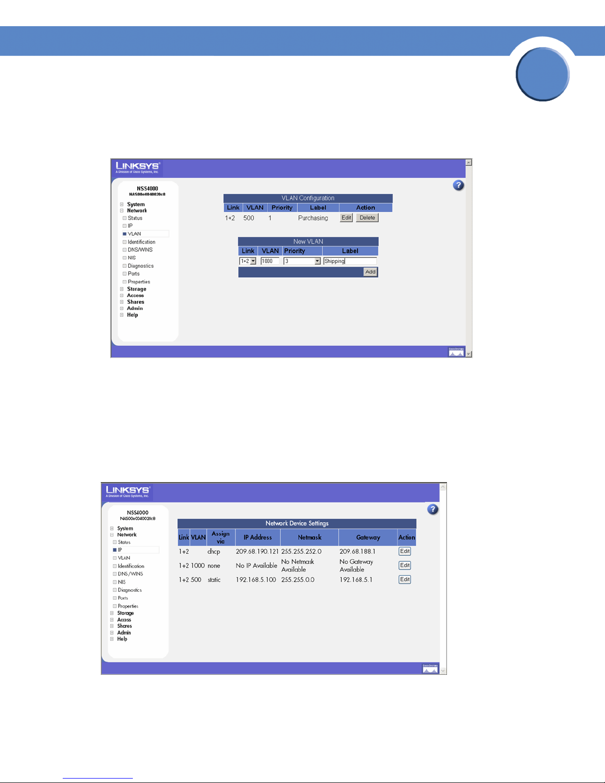
Allowing a VLAN Access to the NSS
To set up a network VLAN to access the NSS:
1. From the Manager Menu, click Network VLAN.
The VLAN Configuration page appears.
Chapter
3
2. In the New VLAN area of the page, set up the following fields:
• Link: Select the Ethernet link on which you want the VLAN to connect to the NSS. Available
options depend on the configuration of your Ethernet link(s).
• VLAN: Enter the ID of the VLAN as it is defined within your network. The range of valid VLAN
IDs is from 0 to 4095.
• Priority: Select the QoS priority for the VLAN traffic as it is defined for your network. Valid
options range from 0 to 7 (as defined by the IEEE 802.1p standard). VLAN Ethernet frames
contain a three-bit priority tag ranging from 0 to 7 (where 0 is best effort and 7 is networkcritical traffic).
Chapter 3: Network
Allowing a VLAN Access to the NSS
22
Chapter
Network Storage System (NSS) Administrator Guide
• Label: Enter a text description for the VLAN (for example, "Data", "Voice", "Video", etc.). It
can be made up of alphanumeric characters. Note that this description is used solely as a
reference within the NSS interface and does not affect its operation.
3
3. Click Add.
The newly added VLAN appears in the VLAN Configuration table. The VLAN configuration
ONLY takes effect after you configure the IP address for the VLAN. A message appears to
advise that the VLAN does not take effect until you configure the IP address.
4. Click OK.
The Network IP page appears. The newly added VLAN appears in the list.
5. Click Edit for the VLAN.
Chapter 3: Network
Allowing a VLAN Access to the NSS
23
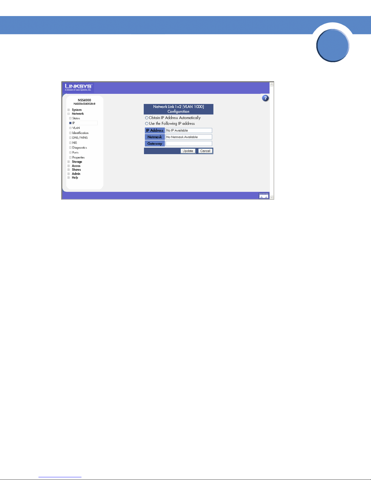
The Network Configuration page appears.
Chapter
Network Storage System (NSS) Administrator Guide
3
6. Click one of the following, depending on how you want to assign the VLAN IP addressing:
• Obtain IP Address Automatically: Use a DHCP server to retrieve the IP address, netmask
address, and gateway address for the VLAN.
• Use the Following IP address: Enter the IP configuration details manually.
7. Click Update.
Chapter 3: Network
Allowing a VLAN Access to the NSS
24
Network Storage System (NSS) Administrator Guide
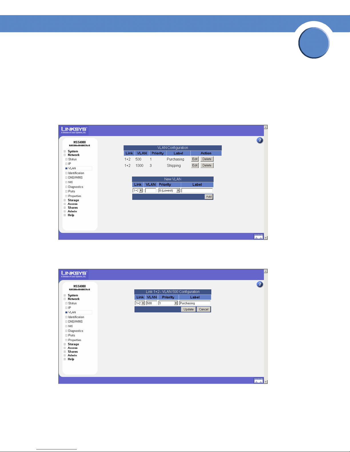
Changing a VLAN Configuration
After you set up a VLAN to access the NSS, you can change its configuration details.
To edit a VLAN configuration:
1. From the Manager Menu, click Network VLAN.
The VLAN Configuration page appears.
Chapter
3
2. Click Edit for the VLAN you want to change.
The VLAN Configuration page appears.
3. Make changes to any of the VLAN configuration fields as required.
4. Click Update.
Chapter 3: Network
Changing a VLAN Configuration
25
Chapter
Network Storage System (NSS) Administrator Guide
Removing a VLAN’s Access to the NSS
All connected VLANs appear when you first display the VLAN Configuration page. You can delete
the connection between a VLAN and the NSS. Note that deleting the VLAN only affects the VLAN’s
ability to access the NSS. It does not impact the VLANs operation within your network.
To disconnect a VLAN’s access to the NSS:
1. From the Manager Menu, click Network VLAN.
The VLAN Configuration page appears.
3
2. From the VLAN Configuration table, click Delete for the VLAN you want to remove.
The VLAN disappears from the VLAN Configuration table and no longer has access to the NSS.
Chapter 3: Network
Removing a VLAN’s Access to the NSS
26
Chapter
Network Storage System (NSS) Administrator Guide
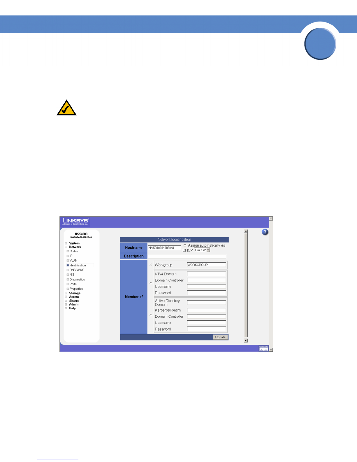
Configuring the NSS Network Identification
The Network Identification page is where you configure the network identity of the NSS, including
the hostname and domain membership.
NOTE: Before you join the NSS to an NTv4 or Active Directory Service (ADS) domain, make
sure you do the following:
• Configure the IP and DNS information.
• Set up your user and group ID ranges on the User/Group Settings page. (see Configuring the
User/Group Settings) You cannot make changes to the User or Group ID range after the
domain is joined.
To configure the NSS network identity:
1. From the Manager Menu, click Network Identification.
3
The Network Identification page appears.
2. In the Hostname field, enter the name you want to use for the NSS. Note any special naming
restrictions or conventions enforced by the domain(s) into which the NSS is being joined.
Chapter 3: Network
Configuring the NSS Network Identification
27

Chapter
Network Storage System (NSS) Administrator Guide
Warning: If you change the hostname, any current CIFS connections to shares on the NSS will
be disconnected.
3. To assign the hostname for the NSS using the DHCP server, select Assign automatically via
DHCP. If the DHCP server is not available or if it is not configured to supply a hostname, the NSS
hostname is assigned using the information entered in the Hostname field.
4. In the Description field, enter the textual description for the NSS as you want it to appear in the
file manager window for your users.
5. Select the type of network into which you are making the NSS a member from the following
options:
• Workgroup: Make the NSS part of a peer-to-peer network.
• NTv4 Domain: Make the NSS a part of a pre-Windows 2000 domain. If you select this
option, set up the following fields:
- NTv4 Domain: Enter the domain name.
3
- Domain Controller: Enter the hostname or IP address of the domain controller.
- Username: Enter the username of an account that has administrator privileges for this
domain.
- Password: Enter the password for the administrator account.
• Member of Active Directory domain: Make the NSS part of an Active Directory (ADS)
domain. If you select this option, set up the following fields:
- Active Directory Domain: Enter the domain name.
- Domain Controller: Enter the hostname or IP address of the domain controller.
- Kerberos Realm: Enter the name of your Kerberos realm. If you are not sure what to enter
here, enter the domain name. In most standard Windows domain installations, this is the
correct value.
- Username: Enter the username of an account that has administrator privileges for this
domain.
- Password: Enter the password for the administrator account.
6. Click Update.
If you configured the NSS to join a domain, when you click Update, the domain join occurs. The
NSS configuration interface displays the status of the domain join (i.e., successful or not
successful).
Chapter 3: Network
Configuring the NSS Network Identification
28
 Loading...