

Page 1

Wireless Access Control System
SYSTEM
POWER
DISPLAY
CONTRAST
RESET
RADIO
RADIO
READER IN
1
DECODE
ACCESS GRANTED
NETWORK DATA
ACCESS OUT DATA
READER KEYPAD
PERIPHERALS
CHANNEL A CHANNEL B CHANNEL C CHANNEL D
N.O. COM.
MEMORY EXPANSION CARD
ACCESS OUT
WARNING
SEVERE
ELECTRICAL
DAMAGE
LARGE (128 K)
X-LARGE (256 K)
KEYPAD IN
B
1BO
SMALL (16 K )
MEDIUM (64 K)
TURN THE POWER SWITCH OFF BEFORE INSTALLING OR
REMOVING THIS MEMORY EXPANSION CARD
NETWORK
O1O1O
1
2
3
4
5
6
7
8
9
0
#
*
RELAYS
ACCESS A
ACCESS B
ACCESS C
ACCESS D
MAGIC WAND
OBSTACLE
EXTERNAL CONTROL
N.C. N.O. COM. N.C. N.O. COM.
N.C. N.O.
RS-232
ON
OFF
POWER
EARTH
GROUND
AC POWER
DC POWER
INPUT
INPUT
COM.
14 - 24 VAC12 - 35 VDC
N.C.
Installation & Programming Instructions
Version 5.0
(760) 438-7000 • FAX (760) 438-7043
USA & Canada (800) 421-1587 & (800) 392-0123
Toll Free FAX (800) 468-1340
www.linearcorp.com
For AM/II
Page 2

TABLE OF CONTENTS
FEATURES . . . . . . . . . . . . . . . . . . . . . . . . . . . . . . . . . . . . 3
Remote Access Software . . . . . . . . . . . . . . . . . . . . . . . . . . 3
AM/II ACCESSORIES . . . . . . . . . . . . . . . . . . . . . . . . . . . . . . . 4
AM/II FEATURES . . . . . . . . . . . . . . . . . . . . . . . . . . . . . . . . . 5
SYSTEM HARDWARE BLOCK DIAGRAM . . . . . . . . . . . . . . . . . . . . 6
BUTTON SCHEDULE . . . . . . . . . . . . . . . . . . . . . . . . . . . . 8
DOOR SCHEDULES . . . . . . . . . . . . . . . . . . . . . . . . . . . . 9
TIME ZONES . . . . . . . . . . . . . . . . . . . . . . . . . . . . . . . 10
ANTI-PASSBACK & KEYPAD STRIKEOUT . . . . . . . . . . . . . . . 11
VALIDATION GROUPS . . . . . . . . . . . . . . . . . . . . . . . . . . 12
EVENT LOG . . . . . . . . . . . . . . . . . . . . . . . . . . . . . . . . 13
REMOTE DEVICES . . . . . . . . . . . . . . . . . . . . . . . . . . . . 14
ACCESS MEDIA . . . . . . . . . . . . . . . . . . . . . . . . . . . . . . 15
RELAY OUTPUTS & SENSING INPUTS . . . . . . . . . . . . . . . . . 16
RS-232 PORT . . . . . . . . . . . . . . . . . . . . . . . . . . . . . . . 17
ACCESS OUT & NETWORK TERMINALS . . . . . . . . . . . . . . . . 18
MEMORY UTILITIES . . . . . . . . . . . . . . . . . . . . . . . . . . . 19
PRE-INSTALLATION PLANNING . . . . . . . . . . . . . . . . . . . . . . . . 20
INSTALLATION OUTLINE . . . . . . . . . . . . . . . . . . . . . . . . . . . 20
WIRELESS INSTALLATION TIPS . . . . . . . . . . . . . . . . . . . . . . . 21
Signals Through Construction Materials . . . . . . . . . . . . . . . . . . 21
Transmitters in Vehicles . . . . . . . . . . . . . . . . . . . . . . . . . . 21
PRE-INSTALLATION . . . . . . . . . . . . . . . . . . . . . . . . . . . . . . 21
Unpacking the System . . . . . . . . . . . . . . . . . . . . . . . . . . . 21
Installing the Memory Module . . . . . . . . . . . . . . . . . . . . . . . 21
MOUNT UNIT . . . . . . . . . . . . . . . . . . . . . . . . . . . . . . . . . . 22
EARTH GROUND & POWER CONNECTIONS . . . . . . . . . . . . . . . . . 23
Earth Ground . . . . . . . . . . . . . . . . . . . . . . . . . . . . . . . 23
Power . . . . . . . . . . . . . . . . . . . . . . . . . . . . . . . . . . . 23
REMOTE DEVICE WIRING REQUIREMENTS . . . . . . . . . . . . . . . . . 24
Cable Type . . . . . . . . . . . . . . . . . . . . . . . . . . . . . . . . 24
Load Number . . . . . . . . . . . . . . . . . . . . . . . . . . . . . . . 24
ANTENNA HOOK-UP . . . . . . . . . . . . . . . . . . . . . . . . . . . . . . 25
REMOTE RADIO RECEIVER CONNECTIONS . . . . . . . . . . . . . . . . . 25
REMOTE KEYPAD CONNECTIONS . . . . . . . . . . . . . . . . . . . . . . 26
REMOTE PROXIMITY RECEIVER . . . . . . . . . . . . . . . . . . . . . . . 26
CARD READER INTERFACE . . . . . . . . . . . . . . . . . . . . . . . . . . 27
CONTROL INPUTS . . . . . . . . . . . . . . . . . . . . . . . . . . . . . . . 27
Open Request . . . . . . . . . . . . . . . . . . . . . . . . . . . . . . . 27
Door Sense . . . . . . . . . . . . . . . . . . . . . . . . . . . . . . . . 27
RELAY OUTPUT CONNECTIONS . . . . . . . . . . . . . . . . . . . . . . . 28
Relay Operation Options . . . . . . . . . . . . . . . . . . . . . . . . . . 28
RS-232 PORT CONNECTIONS . . . . . . . . . . . . . . . . . . . . . . . . . 30
Printer Connections . . . . . . . . . . . . . . . . . . . . . . . . . . . . 30
Personal Computer and Data Terminal Connections . . . . . . . . . . . 31
Modem Connections . . . . . . . . . . . . . . . . . . . . . . . . . . . . 31
ACCESS OUT CONNECTIONS . . . . . . . . . . . . . . . . . . . . . . . . . 32
NETWORK CONNECTIONS . . . . . . . . . . . . . . . . . . . . . . . . . . 33
SYSTEM POWER-UP . . . . . . . . . . . . . . . . . . . . . . . . . . . . . . 34
First Time Power-up . . . . . . . . . . . . . . . . . . . . . . . . . . . . . 34
Internal Diagnostic Checks . . . . . . . . . . . . . . . . . . . . . . . . . 34
Watchdog Monitor . . . . . . . . . . . . . . . . . . . . . . . . . . . . . . 34
MEDIA ENCODING . . . . . . . . . . . . . . . . . . . . . . . . . . . . . . . . 34
Transmitter Coding . . . . . . . . . . . . . . . . . . . . . . . . . . . . . 34
Block Coded Transmitters . . . . . . . . . . . . . . . . . . . . . . . . . . 34
Block Coded Cards . . . . . . . . . . . . . . . . . . . . . . . . . . . . . 34
Keypad Entry Codes . . . . . . . . . . . . . . . . . . . . . . . . . . . . 34
DISPLAYS . . . . . . . . . . . . . . . . . . . . . . . . . . . . . . . . . . . . . 35
Radio Indicator . . . . . . . . . . . . . . . . . . . . . . . . . . . . . . . 35
Decode Indicator . . . . . . . . . . . . . . . . . . . . . . . . . . . . . . 35
Access Granted Indicator . . . . . . . . . . . . . . . . . . . . . . . . . . 35
KEYPAD FUNCTIONS . . . . . . . . . . . . . . . . . . . . . . . . . . . . . . 36
Data Entry Keys . . . . . . . . . . . . . . . . . . . . . . . . . . . . . . . 36
Numeric Keypad . . . . . . . . . . . . . . . . . . . . . . . . . . . . . . . 36
[
] Key . . . . . . . . . . . . . . . . . . . . . . . . . . . . . . . . . . . . 36
*
[#] Key . . . . . . . . . . . . . . . . . . . . . . . . . . . . . . . . . . . . 36
Alphanumeric Data Entry . . . . . . . . . . . . . . . . . . . . . . . . . . 36
SYSTEM PROGRAMMING . . . . . . . . . . . . . . . . . . . . . . . . . . . . 37
Entering Program Mode . . . . . . . . . . . . . . . . . . . . . . . . . . . 37
Exiting Program Mode . . . . . . . . . . . . . . . . . . . . . . . . . . . . 37
PROGRAMMING MENU TREES . . . . . . . . . . . . . . . . . . . . . . . . . 38
PROGRAMMING OUTLINE . . . . . . . . . . . . . . . . . . . . . . . . . . . . 40
AREA 01
SINGLE TRANSMITTER PROGRAMMING . . . . . . . . . . . . . . . . . . . 41
Learning Single Transmitters . . . . . . . . . . . . . . . . . . . . . . . . 41
Suspending Single Transmitters . . . . . . . . . . . . . . . . . . . . . . 41
Reactivating Single Transmitters . . . . . . . . . . . . . . . . . . . . . . 41
Status of Single Transmitters . . . . . . . . . . . . . . . . . . . . . . . . 41
Deleting One Single Transmitter . . . . . . . . . . . . . . . . . . . . . . 41
Deleting All Single Transmitters . . . . . . . . . . . . . . . . . . . . . . . 41
AREA 02
BLOCK TRANSMITTERS . . . . . . . . . . . . . . . . . . . . . . . . . . . . . 42
Entering Block Transmitters . . . . . . . . . . . . . . . . . . . . . . . . . 42
Suspending Block Transmitters . . . . . . . . . . . . . . . . . . . . . . . 42
Reactivating Block Transmitters . . . . . . . . . . . . . . . . . . . . . . . 42
Status of Block Transmitters . . . . . . . . . . . . . . . . . . . . . . . . 42
Deleting All Block Transmitters . . . . . . . . . . . . . . . . . . . . . . . 42
AREA 03
OBSTACLE TRANSMITTERS . . . . . . . . . . . . . . . . . . . . . . . . . . 43
Naming Obstacle Transmitters . . . . . . . . . . . . . . . . . . . . . . . 43
Learning Obstacle Transmitters . . . . . . . . . . . . . . . . . . . . . . . 43
Deleting Obstacle Transmitters . . . . . . . . . . . . . . . . . . . . . . . 43
AREA 04
MAGIC WAND TRANSMITTERS . . . . . . . . . . . . . . . . . . . . . . . . . 44
Naming Magic Wand Transmitters . . . . . . . . . . . . . . . . . . . . . 44
Learning Magic Wand Transmitters . . . . . . . . . . . . . . . . . . . . . 44
Deleting Magic Wand Transmitters . . . . . . . . . . . . . . . . . . . . . 44
Page 3

AREA 05
ENTRY CODES . . . . . . . . . . . . . . . . . . . . . . . . . . . . . . . . . 45
Entering Entry Codes . . . . . . . . . . . . . . . . . . . . . . . . . . . 45
Suspending Entry Codes . . . . . . . . . . . . . . . . . . . . . . . . . 45
Reactivating Entry Codes . . . . . . . . . . . . . . . . . . . . . . . . . 45
Status of Entry Codes . . . . . . . . . . . . . . . . . . . . . . . . . . . 45
Deleting One Single Entry Code . . . . . . . . . . . . . . . . . . . . . . 45
Deleting All Entry Codes . . . . . . . . . . . . . . . . . . . . . . . . . . 45
AREA 06
BLOCK CARD CODES . . . . . . . . . . . . . . . . . . . . . . . . . . . . . 46
Entering Block Card Codes . . . . . . . . . . . . . . . . . . . . . . . . 46
Suspending Block Card Codes . . . . . . . . . . . . . . . . . . . . . . 46
Reactivating Block Card Codes . . . . . . . . . . . . . . . . . . . . . . 46
Status of Block Card Codes . . . . . . . . . . . . . . . . . . . . . . . . 46
Deleting All Block Card Codes . . . . . . . . . . . . . . . . . . . . . . . 46
AREA 07
TELEPHONE ENTRY NUMBERS . . . . . . . . . . . . . . . . . . . . . . . . 47
Entering Tenant Names & Numbers . . . . . . . . . . . . . . . . . . . . 47
Deleting Directory Entries . . . . . . . . . . . . . . . . . . . . . . . . . 47
AREA 10
VALIDATION GROUPS . . . . . . . . . . . . . . . . . . . . . . . . . . . . . 48
Configuring Validation Groups . . . . . . . . . . . . . . . . . . . . . . . 48
AREA 11
BUTTON SCHEDULES . . . . . . . . . . . . . . . . . . . . . . . . . . . . . 49
Setting the Channel “A” Button Schedule . . . . . . . . . . . . . . . . . 49
Setting the Channel “B” Button Schedule . . . . . . . . . . . . . . . . . 49
Setting the Channel “C” Button Schedule . . . . . . . . . . . . . . . . . 49
Setting the Channel “D” Button Schedule . . . . . . . . . . . . . . . . . 49
AREA 12
DOOR SCHEDULES . . . . . . . . . . . . . . . . . . . . . . . . . . . . . . 50
Setting the Door Schedules . . . . . . . . . . . . . . . . . . . . . . . . 50
AREA 13
TIME ZONES . . . . . . . . . . . . . . . . . . . . . . . . . . . . . . . . . . 51
Setting the Time Zones . . . . . . . . . . . . . . . . . . . . . . . . . . 51
AREA 20
TIME AND CALENDAR . . . . . . . . . . . . . . . . . . . . . . . . . . . . . 52
Setting the Time . . . . . . . . . . . . . . . . . . . . . . . . . . . . . . 52
Setting the Date . . . . . . . . . . . . . . . . . . . . . . . . . . . . . . 52
Daylight Savings Option . . . . . . . . . . . . . . . . . . . . . . . . . . 52
Setting Keypad Downlight Time . . . . . . . . . . . . . . . . . . . . . . 52
Setting Holiday Dates . . . . . . . . . . . . . . . . . . . . . . . . . . . 52
Setting Expiring Holiday Dates . . . . . . . . . . . . . . . . . . . . . . 52
AREA 21
RELAY SETUP . . . . . . . . . . . . . . . . . . . . . . . . . . . . . . . . . 53
Relay Timing Options . . . . . . . . . . . . . . . . . . . . . . . . . . . 53
Relay Programming . . . . . . . . . . . . . . . . . . . . . . . . . . . . 53
AREA 22
SYSTEM SETUP . . . . . . . . . . . . . . . . . . . . . . . . . . . . . . . . 54
Setting Installation and Unit Names . . . . . . . . . . . . . . . . . . . . 54
Setting Event Log Limits . . . . . . . . . . . . . . . . . . . . . . . . . . 54
Setting Anti-Passback Time . . . . . . . . . . . . . . . . . . . . . . . . 54
Setting Intregral Radio Direction . . . . . . . . . . . . . . . . . . . . . . 54
Setting Network Address . . . . . . . . . . . . . . . . . . . . . . . . . 54
Setting Keypad Strike Outs . . . . . . . . . . . . . . . . . . . . . . . . 54
Setting Door Ajar Time . . . . . . . . . . . . . . . . . . . . . . . . . . . 54
Setting Local Password . . . . . . . . . . . . . . . . . . . . . . . . . . 54
Setting Remote Password . . . . . . . . . . . . . . . . . . . . . . . . . 54
Setting Priority Access Password . . . . . . . . . . . . . . . . . . . . . 54
AREA 23
Facility/Site Codes . . . . . . . . . . . . . . . . . . . . . . . . . . . . . . . . 55
System Site Code . . . . . . . . . . . . . . . . . . . . . . . . . . . . . 55
Transmitter Facility Code . . . . . . . . . . . . . . . . . . . . . . . . . 55
Card Facility Codes . . . . . . . . . . . . . . . . . . . . . . . . . . . . 55
AREA 24
RS-232 PORT SETUP . . . . . . . . . . . . . . . . . . . . . . . . . . . . . 56
Setting RS-232 Device . . . . . . . . . . . . . . . . . . . . . . . . . . 56
Changing Modem Initialization Strings . . . . . . . . . . . . . . . . . . . 56
Setting Modem Termination String . . . . . . . . . . . . . . . . . . . . 56
AREA 25
CONFIGURE REMOTE DEVICES . . . . . . . . . . . . . . . . . . . . . . . 57
Remote Device Programming . . . . . . . . . . . . . . . . . . . . . . . 57
AREA 26
CONFIGURE ACCESS OUT . . . . . . . . . . . . . . . . . . . . . . . . . . 58
Access Out Application Note . . . . . . . . . . . . . . . . . . . . . . . 58
Access Out Setup . . . . . . . . . . . . . . . . . . . . . . . . . . . . . 58
AREA 27
TELEPHONE ENTRY SETUP . . . . . . . . . . . . . . . . . . . . . . . . . . 59
Configuring Directory . . . . . . . . . . . . . . . . . . . . . . . . . . . 59
Setting PBX Dialing Digit . . . . . . . . . . . . . . . . . . . . . . . . . 59
Setting Talk Time . . . . . . . . . . . . . . . . . . . . . . . . . . . . . 59
Editing Display Messages . . . . . . . . . . . . . . . . . . . . . . . . . 59
Deleting All Telephone Entries . . . . . . . . . . . . . . . . . . . . . . 59
Adjusting the Speaker/Microphone Balance . . . . . . . . . . . . . . . . 59
Set Priority Access Function . . . . . . . . . . . . . . . . . . . . . . . . 59
AREA 29
MEMORY MODULE UTILITIES . . . . . . . . . . . . . . . . . . . . . . . . . 60
Sending Memory Module . . . . . . . . . . . . . . . . . . . . . . . . . 60
Receiving Memory Module . . . . . . . . . . . . . . . . . . . . . . . . 60
Copying Memory Module . . . . . . . . . . . . . . . . . . . . . . . . . 60
Printing Memory Module . . . . . . . . . . . . . . . . . . . . . . . . . . 60
Initializing Memory Module . . . . . . . . . . . . . . . . . . . . . . . . 60
AREA 30
SYSTEM REPORTS/UTILITIES . . . . . . . . . . . . . . . . . . . . . . . . . 61
Printing System Report . . . . . . . . . . . . . . . . . . . . . . . . . . 61
Printing Single Transmitter Report . . . . . . . . . . . . . . . . . . . . . 61
Printing Block Transmitter Report . . . . . . . . . . . . . . . . . . . . . 61
Printing Entry Code Report . . . . . . . . . . . . . . . . . . . . . . . . 61
Printing Block Card Report . . . . . . . . . . . . . . . . . . . . . . . . 61
Printing Telephone Entry Report . . . . . . . . . . . . . . . . . . . . . 61
Printing Event Log . . . . . . . . . . . . . . . . . . . . . . . . . . . . . 61
OPERATION OVERVIEW . . . . . . . . . . . . . . . . . . . . . . . . . . . . 62
Standard Operation . . . . . . . . . . . . . . . . . . . . . . . . . . . . 62
Manual Operation . . . . . . . . . . . . . . . . . . . . . . . . . . . . . 62
Magic Wand Transmitters . . . . . . . . . . . . . . . . . . . . . . . . . 62
Obstacle Transmitters . . . . . . . . . . . . . . . . . . . . . . . . . . . 62
SPECIFICATIONS . . . . . . . . . . . . . . . . . . . . . . . . . . . . . . . . 63
Outputs . . . . . . . . . . . . . . . . . . . . . . . . . . . . . . . . . . 63
Inputs . . . . . . . . . . . . . . . . . . . . . . . . . . . . . . . . . . . 63
Hardware . . . . . . . . . . . . . . . . . . . . . . . . . . . . . . . . . 63
Construction . . . . . . . . . . . . . . . . . . . . . . . . . . . . . . . . 63
INDEX . . . . . . . . . . . . . . . . . . . . . . . . . . . . . . . . . . . . . . 64
LINEAR LIMITED WARRANTY . . . . . . . . . . . . . . . . . . . . . . . . . 66
1
Page 4

INTRODUCTION
The AM/II is designed for a broad range of access control
applications. Its wireless design with the proven MegaCode
radio format, the Wiegand and RS-232 interfaces, make it
easily adaptable for virtually any access control requirement.
The AM/II contains a high-gain superheterodyne UHF receiver.
When used with an external antenna, signals can be received
from up to 200 feet away. Two lockable metal enclosures are
available to house the AM/II.
Four dry contact relay outputs are provided to activate four
access devices, such as door strikes, barrier gates, automatic
sliding gates and automatic doors. The relay outputs can also
be used for alarm contact shunting, operator obstacle
triggering, and alarm activation. Two open request pushbutton
inputs are supplied for hardwire activation of the access
devices. Two door sense inputs allow detection of propped
open doors.
The AM/II has an RS-232 interface (bi-directional). The system
can be linked to a printer or personal computer. The event log
feature, for example, makes it possible to keep track of how
many employees are on premises, which employees are
present, and when they clock in and out. With connection to a
personal computer, the AM/II can be programmed locally or
remotely through the telephone system with standard Hayes
compatible modems. System reports can be printed or
captured from the RS-232 port.
The Wiegand interface is for connection to other
manufacturer’s access control systems. The AM/II can act as
a wireless receiver for an existing access control system. When
interconnected to a Sentex Infinity system, the AM/II can
simulate two Sentex card readers, receiving signals from
thousands of transmitters. The AM/II also supports the industry
standard Wiegand26 and Securakey31 data formats for
connecting to other access control panels.
Up to eight AM/II’s can be networked together allowing
information sharing between the units. A common event l og is
retained for all of the networked units.
Four different size memory modules are available. The small,
medium, large and x-large modules allow tailoring the system
to meet the requirements of the installation. The larger the
memory module, the more transmitter ID codes and logged
events can be stored.
Additional remote accessory devices can be connected to the
AM/II. A rugged, die cast, weatherproof keypad (AM-KP) for
manual input of entry codes. A card reader interface (AM-CRI)
can connect to one or two card readers. A proximity receiver
(AM-RPR) provides ultra-short range radio reception for
transmitters. A remote radio receiver (AM-RRR) can be used
to extend the reception capabilities of the AM/II. Up to six
remote accessory devices can be used with each AM/II unit.
User Tx
Keypad &
Remote
Receiver
6-WIRE
LOCAL BUS
Barrier Gate
STANDARD
2-WIRE SIGNAL
CONNECTION
Barrier Gate with Controlled
Door, Remote Receivers and
Remote Keypads.
Access is Controled with
Time Zones.
Safety Edge
Transmitter
BACK NEXT
Modem for Remote
Access & Programming
AM/II
OK
Controlled Door
Keypad
Door
Strike
Proximity
Receiver
User Tx
6-WIRE
LOCAL BUS
STANDARD
2-WIRE DOOR
STRIKE
CONNECTION
2
Page 5

FEATURES
✶ Ideally suited for gated communities, condos, airports,
parking garages, municipal gated parking, office buildings,
government buildings, hospitals, factories, utility
companies, computer facilities, museums, warehouses,
dormitories, banks, libraries, retail stores, hotels/motels,
educational facilities, small commercial buildings and
recreational facilities.
✶ Controls up to four access devices.
✶ Supports thousands of transmitters, entry codes and card
codes (depends on memory module size).
✶ MegaCode radio format featu res over one million possible
transmitter identification codes.
✶ Remote activation from up to 200 feet away.
✶ Integral 2 line by 24 character backlit LCD display.
✶ Real-time print log (RS-232 output to a line printer).
✶ Remote and local programming with a pe rsonal computer.
✶ Sentex30, Securakey31, and Wiegand26 compatible output
to connect to other access control panels.
✶ Block coding for transmitters and cards (just the first and last
number in a “block” needs to be programmed).
✶ Magic wand support (special transmitter for maintenance
personnel).
✶ Obstacle-sensing support with Linear’s MGT Safety Edge
transmitter.
✶ Two door sensing inputs for propped open doors.
✶ Automatic door relock when door sense input is used.
✶ Two request to exit inputs for pushbutton or knox box
activation.
✶ Time scheduled relay activation, 15 time zones with 4
periods each.
✶ Time zone access validation, 15 time zones with 4 periods
each.
✶ Day of week and holiday access validation, up to 24 expiring
holidays and 24 non-expiring holidays.
✶ Door access restriction for each validation group.
✶ Timed anti-passback modes.
Remote Access Software
Either of the following two Windows based software
programs can be downloaded from our website
(www.linearcorp.com)
✶ Access Base - used in networks or single AM/II installations.
✶ Account Manager - used in non-networked, single AM/II
installations.
Door
07:00 ACCESS U SE R 2
07:10 ACCESS U SE R 17
07:14 ACCESS U SE R 34
07:15 ACCESS U SE R 45
07:19 ACCESS U SE R 27
07:23 ACCESS U SE R 56
07:24 ACCESS U SE R 12
07:26 ACCESS U SE R 13
07:26 ACCESS U SE R 23
07:27 ACCESS U SE R 87
07:28 ACCESS U SE R 67
07:29 ACCESS U SE R 98
RECEPTIONIST
Release
CRT
Event
Logging
PRESIDENT'S OFFICE
SPECIAL ACCESS
Small Commercial Installation
with Two Time Zones. Four
Doors: Customer Entrance,
Employee Entrance, Computer
Room & President's Back Door
Card
Reader
CUSTOMER
ENTRANCE
PRESIDENT
LOBBY
ACCOUNTING
Card
Reader
SERVICE
BATH BATH
V.P.
COMPUTER ROOM
SPECIAL ACCESS
SALES
ENG INEER ING
V.P.
SALES
PURCH.
Card
Reader
Keypad
EMPLOYEE
ENTRANCE
CHIEF
ENG .
LAB
CO PIER
AREA
STOR.
COM PUTER
(Two Networked Units)
ROOM
Printer for
Event Logging
AM/II
BACK NEXT
Modem for
Remote
Programming
OK
3
Page 6

AM/II ACCESSORIES
MDT-1
MDTK
2-B utton M egaC ode
Transm itter
Top and front buttons
fu n c tio n th e s a m e to
contro l a single
relay channel.
M egaC ode W ireless K eypad
U ser code is entered on keypad.
Keypad has w eather-proof
construction, easy to read
num bers and is backlit for
use at night. C an be used for up
to 1524 single transm ittte r c o d e s .
MDT-2
3-B utton M egaC ode
Transm itter
Tw o front buttons and a
top button can be used
w ith any relay channel.
ACT-21
1-B utton M egaC ode
M ini Transm itter
D esigned to be used with
the keychain provided.
Activates one relay channel.
SINGLE & BLOCK CODED
TRANSMITTERS
MDT-4
5-B utton M egaC ode
Transm itter
C an control all relay
channels or be used as
a m agic wand transm itter.
ACT-22
2-B utton M egaC ode
M ini Transm itter
D esigned to be used with
the keychain provided.
A c tiv a te s tw o re la y c h a n n e ls .
MGT
Card Reader
In te r fa c e
C onnects to one or
tw o 26-bit or 31-bit card
readers. Functions as
tw o re m o te d e v ic e s .
S u p e r v is e d G a te S a fe t y
Edge Transm itter
C onnects to safety edge
s e n s o r. A c tiv a te s o b s ta c le
relay channel.
AM-CRI
1
2
3
4
5
6
7
8
9
AM-KP
Entry K eypad
O utdoor housing w ith
lighted keypad and tw o
in d ic a to rs . A c tiv a te s o n e
relay channel.
R e m o te P r o x im ity
R eceiver
R e c e iv e s tra n s m itte r
signals from inches
aw ay. For transm itter
activation of specific
a c c e s s p o in t.
*
AM-RPR
0
#
REMOTE ACCESSORY DEVICES
AM-RRR
Rem ote Radio Receiver
H igh-gain rem ote radio
receiver w ith outdoor
housing.
EXA -2000
EXA -1000
Rem ote Antennas
D irectional and om nidirectional antennas for
rem ote placem ent in best
reception areas.
4
Page 7

AM/II FEATURES
3
2
1
4
SYSTEM
POWER
DISPLAY
CONTRAST
RESET
EXPANSION MEMORY CARD
MEMORY EXPANSION CARD
SMALL (16 K)
MEDIUM (64 K)
WARNING
SEVERE
ELECTRICAL
DAMAGE
TURN THE POWER SWITCH OFF BEFORE INSTALLING OR
REMOVING THIS MEMORY EXPANSION CARD
KEYPAD IN
ACCESS OUT
NETWORK
O1O1O
LARGE (128 K)
X-LARGE (256 K)
B
1BO
23
22
21
1. MEMORY EXPANSION CARD
Plug-in memory module. Four sizes available: small, medium, large and
jumbo.
2. RESET BUTTON
Resets and restarts the microprocessor. Runs startup tests.
3. POWER LIGHT
Indicates that DC or AC power is being applied to the unit and that the
POWER switch is turned on.
4. DISPLAY CONTRAST CONTROL
Adjusts the contrast of the unit’s LCD display. Allows setting the display
for maximum readability for different viewing angles.
5. LCD DISPLAY
Backlit, 24-character-per-line, 2-line LCD display. Displays system
operation and programming information.
6. RADIO RANGE KNO B
Controls the gain of the radio receiver. Used to limit the maximum
operating range of transmitters. Turn clockwise for more gain,
counterclockwise for less gain.
7. ANTENNA INPUT
For connection to the EXA-1000 omni-directional or EXA-2000 directional
remote antenna.
8. DATA ENTRY KEYS
Arrow keys are used to scroll through displayed menu trees. OK key is
used as an enter key to accept data entered or selected.
9. RADIO INDICATOR
The RADIO light indicates the presence of RF signal into the unit’s
receiver.
10. NUMERIC KEYPAD
Used for entering data while programming the AM/II.
11. RS-232 PORT
Connects to a serial line printer, PC or data terminal for logging access
transactions. For local programming with a PC or remote programming
with a PC and a modem. Also used to interconnect two AM/II units to copy
the memory between systems.
12. POWER SWITCH
Controls the DC and AC power inputs. This is the master power switch
for the AM/II.
13. EARTH GROUND TERMINAL
For connection to a good earth ground. For electrical safety and optimum
lightning protection, this connection is mandatory.
20
19
5
RADIO
DECODE
ACCESS GRANTED
ACCESS IN DATA
ACCESS OUT DATA
READER KEYPAD
PERIPHERALS
READER IN
1
18
6
7
8
OK
RADIO
CHANNEL A CHANNEL B CHANNEL C CHANNEL D
RELAYS
RS-232
ACCESS A
ACCESS B
N.O. COM.
N.C. N.O. COM. N.C. N.O. COM.
ACCESS C
ACCESS D
MAGIC WAND
OBSTACLE
EXTERNAL CONTROL
17
ON
OFF
POWER
EARTH
GROUND
AC POWER
DC POWER
INPUT
INPUT
N.C. N.O.
14 - 24 VAC12 - 35 VDC
COM.
N.C.
16
15
14. POWER TERMINALS
DC power input terminals for 12 to 35 VDC. AC power input terminals for
14 to 24 VAC. Use either AC or DC power, DO NOT USE BOTH.
15. RELAY INDI C AT ORS AN D AC CESS BU TT ON S
Indicators will light when an output relay is activated. Outputs can be
activated (open) by a transmitter or locked open by pressing an ACCESS
button.
16. EXTERNAL CONTROL INDICATORS
MAGIC WAND indicator lights when the special “MAGIC WAND”
transmitter is activated by a system administrator. OBSTACLE indicator
lights when a signal from a Model MGT safety edge transmitter is
received.
17. RELAY TERMINALS
Connects to the access device to be controlled (door strike, gate operator,
etc.). Open request switch inputs are provided for relay channel s A & B.
18. WIRING STRAIN RELIEF HOOKS
Strain relief hooks are provided on the bottom of the AM/II case. After
wiring is complete, wires can be zip-tied to the strain relief hooks.
19. PERIPHERALS INDICATORS
The DECODE light indicates that the data being received is a valid format
that the unit recognizes. The ACCESS GRANTED indicator lights when
a device that is allowed to have access is triggered. The ACCESS IN and
ACCESS OUT indicators light when da ta is be in g sent or re ceived from
the remote devices.
20. READER IN TERMINALS
Connects to remote accessory devices.
21. KEYPAD IN TERMI N AL S
Connects to remote accessory devices.
22. ACCESS OUT TERMI NA L S
AccessNet Data Bus for connection to other access control units. Sentex
access out format is programmable for connection to Sentex Infinity
systems. Wiegand26 and SecuraKey31 access out formats are
programmable for connection to Wiegand inputs on other access control
units.
23. NETWORK TERMINALS
For connection to other AM/II units. Up to 8 units can be n etworked
together.
9
10
11
12
13
14
5
Page 8

SYSTEM HARDWARE BLOCK DIAGRAM
TRANSMITTERS
2
TRANSMITTERS
AM/II CONTROL
USER'S
OBSTACLE
3
1
ANOTHER
AM/II
INDICATORS
MEMORY
MODULE
NETWORK
TERMINALS
EXTERNAL
ACCESS
CONTROL
ACCESS OUT
PANEL
TERMINALS
DISPLAY KEYBOARD
MICROPROCESSOR
KEYPAD
TERMINALS
READER
TERMINALS
7
DOOR SENSE
& OPEN REQ.
RADIO
RS-232
PORT
RELAY
TERMINALS
4
ACCESS DEVICES
(DOOR STRIKES,
OPERATORS)
ANOTHER
AM/II
UP TO 8
NETWORK
UNITS
6
8
AM-KP
KEYPAD
[DV4]
AM-RPR
RECEIVER
[DV1]
AM-KP
KEYPAD
[DV5]
& PUSHBUTTONS
AM-RRR
RECEIVER
[DV2]
AM-KP
KEYPAD
[DV6]
MAGNETIC
SWITCHES
5
AM-CRI
READER
[DV3]
6
Page 9

➀
AM/II CONTROL
The AM/II is a microprocessor based, world class access
control system with a built-in superheterodyne radio receiver.
The microprocessor runs the entire system, granting access,
performing system “housekeeping” functions, displaying
information, reading inputs and controlling outputs.
Programming information and event logs are stored in the
removable memory module. The soft touch silicone keypad and
numeric keys are used for data entry. The plug-in terminal
blocks connect to access devices, power, remote devices and
sensing inputs. The RS-232 port connects to external computer
equipment for event logging and system programming.
➁
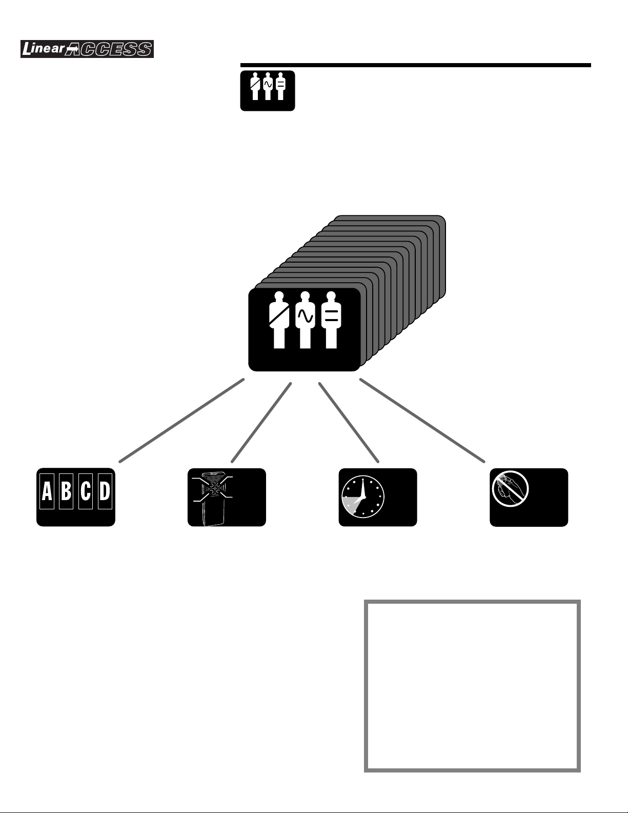
RADIO TRANSMITTERS
Many models of transmitters can be used with the AM/II. Some
are individually coded, others are coded in blocks of numbers.
Both code types will appear to functio n the same to the end
users. The users will activate their transmitter to attempt to gain
access. When the transmitted signal is detected by an AM/II
receiver, the control decides if the user is currently allowed
access. If the programming in the AM/II determines that the
user can have access at that time, the programmed output
relay will activate. Model MGT gate obstacle transmitters can
also send signals to the AM/II.
➄
OPEN REQUEST AND DOOR SENSE
INPUTS
The open request inputs wire to pushbuttons or knox boxes so
that users can activate access devices without needing their
card code or transmitter. Open request pushbuttons are usually
next to the controlled portal inside the controlled area. Doo r
sense inputs are wired to normally closed magnetic or
mechanical switches attached to the door.
➅
REMOTE DEVICES
The remote devices communicate with the AM/II through a
common electrical buss. Each device is set to a unique device
address so the AM/II can recognize each unit as an individual.
Currently available remote devices include entry keypads,
remote radio receivers, radio proximity receivers and card
reader interfaces.
➆
EXTERNAL ACCESS CONTROL
Access control panels from other manufacturers can be
connected to the AM/II. The AM/II can serve as a remote device
for the external panel. The external panel can validate the data
coming from the AM/II and perform its own access functions.
➂
EXTERNAL ANTENNA
The AM/II control has a type “F” antenna connector. The
external antenna is connected with co-ax cable to the
connector. A Model EXA-1000 (omni-directional), or Model
EXA-2000 (directional) antenna is used to receive signals from
the user’s transmitters. The radio gain control knob can be used
to custom tailor the reception area to the installation.
➃
ACCESS DEVICES
The access devices wired to the relay terminals control specific
access portals. When a user is granted access by the AM/II the
access device activates (usually for a timed period).
➇
NETWORKED UNITS
Up to eight AM/II’s can be networked together to function in
unison. Each AM/II functions as an independent unit, but
programming and event logging is shared between all units.
Cards, codes and transmitters can be programmed to activate
a specific AM/II unit.
7
Page 10

CONCEPTS
The following pages provide a foundation for
learning the access control concepts used in
BOTTOM-LEFT
BUTTON
LEFT
BUTTON
the AM/II system.
BOTH
FUNCTION
AS LEFT
BUTTON
LEFT
BUTTON
TOP
BUTTON
RIGHT
BUTTON
BOTTOM-RIGHT
BUTTON
TOP
BUTTON
BOTH EQUALS
TOP BUTTON
BUTTON SCHEDULE
?
?
?
?
BUTTON
SCHEDULE
RIGHT
BUTTON
ANY TRANSMITTER
BUTTON CAN BE
PROGRAMMED TO
ACTIVATE ANY
RELAY CHANNEL
RIGHT
BUTTON
Select which transmitter buttons
activate which relay channels
RELAY
CHANNEL "A"
A
RELAY
CHANNEL "B"
B
RELAY
CHANNEL "C"
C
RELAY
CHANNEL "D"
LEFT
BUTTON
LEFT
BUTTON
BUTTON DEFAULTS
CHANNEL "A" = LEFT
CHANNEL "B" = RIGHT
CHANNEL "C" = BOTTOM-LEFT
CHANNEL "D" = BOTTOM-RIGHT
8
D
SPECIAL INFORMATION
The button schedule must be set before
programming any validation group.
Each validation group can have different
button schedules.
To avoid confusion, using the same button
schedule for all validation groups is
recommended.
Page 11

CONCEPTS
DOOR SCHEDULES
A
BCD
DOOR SCHEDULE
DOOR SCHEDULE
Select which relay channels a validation
group can access
UP TO 15 DIFFERENT DOOR
SCHEDULES [DS1 - DS15] CAN BE SET
RELAY
CHANNEL "A"
RELAY
CHANNEL "B"
EACH DOOR SCHEDULE SETS WHICH
RELAY CHANNEL(S) THAT
THE SCHEDULE CAN ACTIVATE
RELAY
CHANNEL "C"
RELAY
CHANNEL "D"
SPECIAL INFORMATION
Program door schedules before
programming validation groups.
Door schedule 0 [DS0] always allows
access to all four door relay channels.
Up to 15 door schedules can be
programmed.
9
Page 12

CONCEPTS
TIME ZONES
TIME
ZONE
TIME
ZONE
Select the days of the week & what
times that a validation group
will be active
UP TO 15 DIFFERENT TIME ZONES
[TZ1 - TZ15] CAN BE SET
VALID DAYS
❍ SUN
❍ MON
❍ TUES
❍ WED
VALID DAYS SET WHICH DAY(S) THE
TIME ZONE IS ACTIVE. HOLIDAY
OPTION ALLOWS ACCESS ON
PROGRAMMED HOLIDAY DAYS.
❍ THURS
❍ FRI
❍ SAT
❍ HOLIDY
TIME PERIOD 1
BEGIN TIME: 00:00
END TIME: 00:00
TIME PERIOD 2
BEGIN TIME: 00:00
END TIME: 00:00
UP TO FOUR SEPARATE TIME PERIODS
CAN BE SET FOR EACH TIME ZONE.
ACCESS WILL ONLY BE GRANTED
DURING A TIME PERIOD.
TIME PERIOD 3
BEGIN TIME: 00:00
END TIME: 00:00
SPECIAL INFORMATION
Time zones also enables holiday
schedules for a validation group.
Up to 15 time zones can be programmed.
Note: 00:00 settings for all time periods in
a time zone allows 24-hour access.
Time zone 0 [TZ0] always allows 24-hour
access.
TIME PERIOD 4
BEGIN TIME: 00:00
END TIME: 00:00
10
Page 13

CONCEPTS
ANTI-PASSBACK & KEYPAD STRIKEOUT
WHEN ANTI-PASSBACK
OPTION IS ENABLED AND
TRANSMITTER IS ACTIVATED...
ANTI-
PASSBACK
& STRIKEOUT
“tailgating” by unauthorized users,
Timed anti-passback prevents
keypad strikeout discourages
THE TRANSMITTER WILL NOT HAVE
ACCESS AGAIN UNTIL ANTI-PASSBACK
TIME EXPIRES
keycode “guessing”
1
2
3
4
5
6
7
8
9
0
#
*
WHEN KEYPAD STRIKEOUTS ARE SET,
AFTER THE SET NUMBER OF WRONG
CODE ATTEMPTS THE KEYPAD WILL
"LOCKOUT" IGNORING FURTHER
ATTEMPTS UNTIL ONE MINUTE
PASSES
YELLOW LIGHT SHOWS
LOCKED OUT CONDITION
1
2
3
4
5
6
7
8
9
0
#
*
SPECIAL INFORMATION
Anti-passback time can be programmed to
1, 2, 3 or 4 minutes.
Intregral radio direction must be set to IN
for anti-passback to function.
Keypad strikeout can be set from one to
seven failed attempts.
11
Page 14
CONCEPTS
VALIDATION GROUPS
Control who gets access to which areas
VALIDATION GROUP
and at what times
DOOR SCHEDULE
VALIDATION GROUP
?
?
?
?
BUTTON
SCHEDULE
EACH VALIDATION GROUP SELECTS
A DOOR SCHEDULE, BUTTON
SCHEDULE, TIME ZONE AND
ANTI-PASSBACK OPTION
UP TO 15 VALIDATION GROUPS
[VG1 - VG15] CAN BE SET
TIME
ZONE
ANTI-
PASSBACK
& STRIKEOUT
SPECIAL INFORMATION
Set door schedules, time zones, button
schedules and anti-passback timer before
programming validation groups.
12
Up to 15 validation groups can be
programmed. Each selects a door
schedule, time zone, button schedule and
anti-passback option.
Validation group "0" has full access at all
times.
Page 15

CONCEPTS
EVENT LOG
10:52:42 06/20/95 0:0 sTx[00001] ->{A}
Sherie Price AM/II Unit #1
10:52:42 06/20/95 0:2 Crd[01470] ->{D}
Tony Lobianco Front Door Card Reader
10:54:14 06/20/95 0:0 sTx[00003] ->{A}
John Phillips AM/II Unit #1
10:54:21 06/20/95 0:1 Kpd[2003] ->{C}
Moe Howard Front Gate Keypad
10:54:28 06/20/95 0:0 sTx[00002] ->{A}
Jack Hess AM/II Unit #1
EVENT LOG
SAMPLE REAL-TIME EVENT PRINTOUT
10:52:42 06/20/95 0:0 sTx[00001] ->{A}
AM/II Unit #1
10:52:42 06/20/95 0:2 Crd[01470] ->{D}
Front Door Card Reader
10:54:14 06/20/95 0:0 sTx[00003] ->{A}
AM/II Unit #1
10:54:21 06/20/95 0:1 Kpd[2003] ->{C}
Front Gate Keypad
10:54:28 06/20/95 0:0 sTx[00002] ->{A}
AM/II Unit #1
Keeps a record of all access
transactions and supervisory conditions
REAL-TIME EVENT LOG PRINTS EACH
EVENT AS IT HAPPENS
TOP LINE OF EVENT SHOWS:
TIME & DATE
NETWORK ADDRESS : REMOTE DEVICE ADDRESS
STORED EVENT LOG SHOWS ALL
EVENTS FROM MOST RECENT TO
OLDEST STORED EVENT
BOTTOM LINE OF EVENT SHOWS:
DIRECTION OF ENTRY & RELAY LETTER
MEDIA TYPE & ID#
SAMPLE STORED EVENT LOG
Event Log Report Jun 22, 1995 09:56:39 Page 001
Installation: South Hills Apartments AM/II Unit #1
08:55:35 06/22/95 0:0 sTx[00003] ->{B}
Unit #1
08:51:21 06/22/95 0:2 Crd[01470] ->{B}
Front Door Card Reader
08:45:49 06/22/95 0:0 sTx[00001] ->{A}
Unit #1
12:28:42 06/20/95 0:0 Obs[1] Obstacle Txmtr Trouble
11:02:42 06/20/95 0:0 Exit Program Mode
11:02:42 06/20/95 0:0 Program Mode Timed Out
DEVICE NAME
SPECIAL INFORMATION
The number of possible stored events
depends on the size of memory installed
and the amoumt of other data stored.
The stored event log can be set to retain
up to 500, 1000, 2000, 5000, maximum or
no events.
Stored event log can be printed in total,
from the last report or from a selected
date.
13
Page 16

CONCEPTS
REMOTE DEVICES
MODEL AM-KP ENTRY KEYPAD
ACCEPTS ENTRY CODES AS USERS
KEY THEM IN
REMOTE
DEVICE
1
2
4
5
7
8
0
*
Accept input from various media
EACH REMOTE DEVICE CAN BE WIRED
TO THE AM/II AND HAS A ROTARY
SWITCH THAT SELECTS THE DEVICE
ADDRESS
3
6
9
#
MODEL AM-CRI CARD READER INTERFACE
ACCEPTS CARD CODES FROM ONE OR
TWO CARD SWIPE READERS
MODEL AM-RPR RADIO PROXIMITY RECEIVER
ACCEPTS ID CODES FROM
TRANSMITTERS AS USERS ACTIVATE
THEM NEXT TO RECEIVER
14
MODEL AM-RRR REMOTE RADIO RECEIVER
ACCEPTS ID CODES FROM
TRANSMITTERS AS USERS ACTIVATE
THEM WITHIN RANGE OF THE REMOTE
RECEIVER'S ANTENNA
Page 17

HARDWARE & MEDIA
ACCESS MEDIA
The following pages provide a foundation for
learning the hardware devices and access
control media used in the AM/II system.
SINGLE TRANSM ITTERS
UNIQUELY CODED AT THE FACTORY
AND PRO G RAM MED O NE AT A TIM E
N O T E : S IN G L E T R A N S M IT T E R S
ARE NOT COM PATIBLE W ITH
ACC ESSBASE O R ACCO UNT M ANAG ER
BLOCK CODED TRANSM ITTERS
SEQUENTALLY CODED AT THE
FACTORY AND PRO GRAM M ED BY
ENTERING THE STARTING AND
ENDING BLOCK NUM BERS
ACCESS MEDIA
Cards, keypad codes &
transmitters (CCT’s)
BLOCK CODED CARDS
SEQUENTALLY CODED AT THE
FACTORY AND PRO GRAM M ED BY
ENTERING THE STARTING AND
ENDING BLOCK NUM BERS
KEYPAD EN TR Y CODES
PRO G RAMM ED BY THE INSTALLER,
CAN BE FROM TW O TO EIGHT DIGITS
LONG - RECOMMENDED THAT ALL
CODES BE THE SAME LENGTH - FOR
HIGHEST SECURITY, CODES SHOULD
BE AT LEAST FOUR DIGITS LONG
15
Page 18

HARDWARE & MEDIA
R
RELAY OUTPUTS & SENSING INPUTS
Control access devices and sense
OUTPUTS & INPUTS
RELAY OUTPUTS
ELECTRICALLY ISOLATED CONTACTS (3 AMPS, 30 VOLTS MAXIMUM)
●
●
NORMALLY OPEN AND NORMALLY CLOSED CONTACTS
●
PROGRAMMABLE FOR TIME DURATION, PULSE, TOGGLE AND LATCH OUTPUTS
SENSING INPUTS
OPEN REQUEST INPUT AVAILABLE FOR RELAY CHANNELS A & B (NORMALLY OPEN SWITCH)
●
●
DOOR SENSE INPUT AVAILABLE FOR RELAY CHANNELS A & B (NORMALLY CLOSED SWITCH)
auxiliary inputs
RELAY
CHANNEL "A"
A
TYPICAL INSTALLATION
RELAY
CHANNEL "B"
CHANNEL "C"
B
OPEN
REQUEST
PUSHBUTTON MAGNETIC
DOOR
STRIKE
DOOR
SENSE
SWITCH
DOOR
STRIKE
RELAY
C
RELAY
CHANNEL "D"
D
OBSTACLE
TRANSMITTE
CONTROLLED
16
ACCESS
DOOR 1
CONTROLLED
ACCESS
DOOR 2
BARRIER
GATE
Page 19

HARDWARE & MEDIA
SERIAL PRINTER
PRINTS REAL-TIM E EVENT LOG
●
PRINTS SYSTEM REPO RTS
●
USE M ODEL A2P CABLE
●
COMPUTER TERMINAL
DISPLAYS REAL-TIM E EVENT LOG
●
DISPLAYS SYSTEM REPO RTS
●
LO CALLY PRO G RAM AM /II
●
USE M ODEL A2C CABLE
●
PERSONAL COMPUTER
RS-232 PORT
RS-232
PORT
MODEL A2P
PRINTER
CABLE
MODEL A2C
COMPUTER
CABLE
For printing event log, programming
and transferring memory between units
SERIAL
PRINTER
TERMINAL
DISPLAYS REAL-TIM E EVENT LOG
●
DISPLAYS SYSTEM REPO RTS
●
LO CALLY PRO G RAM AM /II
●
STORE AM /II M EMORY TO DISK
●
L O A D A M /II M E M O R Y F R O M D IS K
●
USE M ODEL A2C CABLE
●
COMPUTER MODEM
CONNECTS TO AM/II RS-232 PORT
●
ANSW ERS CALLS FROM REM OTE COM PUTER
●
REMOTELY PROGRAM AM /II
●
R E M O T E L Y S T O R E A M /II M E M O R Y T O D IS K
●
R E M O T E L Y L O A D A M /II M E M O R Y F R O M D IS K
●
REM OTELY DISPLAY STORED EVENT LOG
●
REMOTELY DISPLAY SYSTEM REPORTS
●
USE M ODEL A2M CABLE
●
AM/II INTERCONNECT
C O N N E C T S T W O A M /II U N IT S T O G E T H E R
●
TRANSFER M EMORY BETW EEN UNITS
●
USE M ODEL A2A CABLE
●
MODEL A2M
MODEM
CABLE
PERSONAL
COMPUTER
MODEM
MODEL A2A
INTERCONNECT
CABLE
17
Page 20

HARDWARE & MEDIA
ACCESS OUT & NETWORK TERMINALS
ACCESS OUT TERMINALS
PASSES ACCESS OUT INFORMATION
●
TO AN EXTERNAL ACCESS CONTROL
SYSTEM
SUPPORTS WIEGAND26
●
SECURAKEY31, AND SENTEX30
DATA FORMATS
EXTERNAL ACCESS PANEL CAN BE
●
USED FOR VALIDATION OF
PASS-THROUGH DATA FROM THE AM/II
SIMPLE THREE-WIRE CONNECTION
●
ACCESS OUT
& NETWORK
SYSTEM
POWER
DISPLAY
CONTRAST
RESET
EXPANSION MEMORY CARD
MEMORY EXPANSION CARD
SMALL (16 K)
MEDIUM (64 K)
WARNIN G
SEVERE
ELECTRICAL
DAMAGE
TURN THE POWER SWITCH OFF BEFORE INSTALLING OR
REMOVING THIS MEMORY EXPANSION CARD
ACCESS OUT
KEYPAD IN
NETWORK
O1O1O
For linking an AM/II to an external
access control panel and connecting
multiple AM/II’s together
RELAYS
LARGE (128 K)
X-LARGE (256 K)
B
1BO
RADIO
RADIO
DECODE
ACCESS GRANTED
ACCESS IN DATA
ACCESS OUT DATA
READER KEYPAD
PERIPHERALS
CHANNEL A CHANNEL B
1
N.O.
COM.
N.C.
ACCESS A
ACCESS B
ACCESS C
ACCESS D
MAGIC WAND
OBSTACLE
EXTERNAL CONTROL
N.O.
COM.
N.C. N.O.
CHANNEL C
COM.N.C. N.O.COM. N.C.
RS-232
ON
OFF
POWER
EARTH
GROUND
AC POWER DC POWER
INPUT
INPUT
CHANNEL DREADER IN
14 - 24 VAC
12 - 35 VDC
18
NETWORK TERMINALS
UP TO EIGHT AM/II UNITS CAN BE
●
CONNECTED TOGETHER
EVENT LOG IS SHARED BETWEEN
●
THE NETWORKED UNITS
SIMPLE TWO-WIRE
●
RS-485 CONNECTION
SYSTEM
POWER
DISPLAY
CONTRAST
RESET
EXPANSION MEMORY CARD
MEMORY EXPANSION CARD
SMALL (16 K)
MEDIUM (64 K)
WARNIN G
WARNING
SEVERE
ELECTRICAL
DAMAGE
TURN THE POWER SWITCH OFF BEFORE INSTALLING OR
REMOVING THIS MEMORY EXPANSION CARD
ACCESS OUT
NETWORK
O1O1O
LARGE (128 K)
X-LARGE (256 K)
KEYPAD IN
B
1BO
RELAYS
RADIO
RADIO
DECODE
ACCESS GRANTED
ACCESS IN DATA
ACCESS OUT DATA
READER KEYPAD
PERIPHERALS
POWER
CHANNEL A CHANNEL B
1
N.O.
COM.
N.C.
ACCESS A
ACCESS B
ACCESS C
ACCESS D
MAGIC WAND
OBSTACLE
SYSTEM
EXTERNAL CONTROL
DISPLAY
CHANNEL C
CONTRAST
N.O.
COM.
N.C. N.O.
COM.N.C. N.O.COM. N.C.
RESET
EXPANSION MEMORY CARD
MEMORY EXPANSION CARD
SMALL (16 K)
MEDIUM (64 K)
WARNIN G
SEVERE
ELECTRICAL
DAMAGE
TURN THE POWER SWITCH OFF BEFORE INSTALLING OR
REMOVING THIS MEMORY EXPANSION CARD
ACCESS OUT
KEYPAD IN
NETWORK
O1O1O
1BO
CHANNEL DREADER IN
LARGE (128 K)
X-LARGE (256 K)
B
RS-232
ON
OFF
POWER
EARTH
GROUND
AC POWER
DC POWER
INPUT
INPUT
14 - 24 VAC
12 - 35 VDC
RELAYS
RADIO
RADIO
DECODE
ACCESS GRANTED
ACCESS IN DATA
ACCESS OUT DATA
READER KEYPAD
PERIPHERALS
CHANNEL A CHANNEL B
1
N.O.
COM.
N.C.
RS-232
ACCESS A
ACCESS B
ACCESS C
ACCESS D
MAGIC WAND
OBSTACLE
SYSTEM
EXTERNAL CONTROL
POWER
DISPLAY
DC POWER
CHANNEL C
CHANNEL DREADER IN
CONTRAST
N.O.
COM.
N.C. N.O.
COM.N.C. N.O.COM. N.C.
RESET
EXPANSION MEMORY CARD
MEMORY EXPANSION CARD
LARGE (128 K)
SMALL (16 K)
MEDIUM (64 K)
X-LARGE (256 K)
WARNIN G
SEVERE
ELECTRICAL
DAMAGE
TURN THE POWER SWITCH OFF BEFORE INSTALLING OR
REMOVING THIS MEMORY EXPANSION CARD
KEYPAD IN
ACCESS OUT
NETWORK
B
O1O1O1BO1
ON
OFF
POWER
EARTH
GROUND
AC POWER
INPUT
INPUT
14 - 24 VAC
12 - 35 VDC
RELAYS
RADIO
RADIO
DECODE
ACCESS GRANTED
ACCESS IN DATA
ACCESS OUT DATA
READER KEYPAD
PERIPHERALS
CHANNEL A CHANNEL B CHANNEL C CHANNEL DREADER IN
N.O.
COM.
N.C. N.O. COM.
ACCESS A
ACCESS B
ACCESS C
ACCESS D
MAGIC WAND
OBSTACLE
EXTERNAL CONTROL
N.C.
RS-232
ON
OFF
POWER
EARTH
GROUND
AC POWER
DC POWER
INPUT
INPUT
14 - 24 VAC12 - 35 VDC
N.O.
COM. N.C.
N.O.
COM.N.C.
Page 21

HARDWARE & MEDIA
MEMORY UTILITIES
COPYING MEMORY DATA
MEMORY MODULE INFORMATION
●
CAN BE SENT TO AND RECEIVED
FROM ANOTHER AM/II THROUGH THE
RS-232 PORT USING THE MODEL A2A
CABLE
MEMORY
UTILITIES
POWER
DISPLAY
CONTRAST
RESET
MEMORY EXPANSION CARD
LARGE (128 K)
SMALL (16 K)
MEDIUM (64 K)
X-LARGE (256 K)
WARNIN G
SEVERE
ELECTRICAL
DAMAGE
TURN THE POWER SWITCH OFF BEFORE INSTALLING OR
REMOVING THIS MEMORY EXPANSION CARD
KEYPAD IN
ACCESS OUT
NETWORK
O1O1O
1BO
RADIO
DECODE
ACCESS GRANTED
ACCESS IN DATA
ACCESS OUT DATA
READER KEYPAD
B
1
MODEL A2A
For copying and transferring memory
module data
RS-232
ACCESS A
ACCESS B
ACCESS C
ON
ACCESS D
MAGIC WAND
CHANNEL A CHANNEL B
N.O.
COM.
N.C.
CABLE
OFF
OBSTACLE
N.O.
COM.
POWER
EARTH
GROUND
DC POWER
AC POWER
INPUT
CHANNEL C
CHANNEL DREADER IN
12 - 35 VDC
INPUT
14 - 24 VAC
N.C. N.O.
COM.N.C. N.O.COM. N.C.
POWER
DISPLAY
CONTRAST
RESET
MEMORY EXPANSION CARD
SMALL (16 K)
MEDIUM (64 K)
WARNIN G
SEVERE
ELECTRICAL
DAMAGE
TURN THE POWER SWITCH OFF BEFORE INSTALLING OR
REMOVING THIS MEMORY EXPANSION CARD
KEYPAD IN
ACCESS OUT
NETWORK
O1O1O
1BO
LARGE (128 K)
X-LARGE (256 K)
B
RADIO
ACCESS A
DECODE
ACCESS B
ACCESS GRANTED
ACCESS C
ON
ACCESS D
ACCESS IN DATA
ACCESS OUT DATA
MAGIC WAND
READER KEYPAD
CHANNEL A CHANNEL B
1
N.O.
COM.
N.C.
N.O.
OFF
OBSTACLE
CHANNEL C
COM.
N.C. N.O.
COM.N.C. N.O.COM. N.C.
EARTH
GROUND
AC POWER
DC POWER
INPUT
INPUT
CHANNEL DREADER IN
14 - 24 VAC
12 - 35 VDC
SENDING AND RECEIVING MEMORY DATA
MEMORY MODULE DATA CAN BE
●
SENT AND RECEIVED THROUGH THE
RS-232 PORT OVER THE PHONE LINE
USING A MODEM WITH THE MODEL
A2M CABLE
MEMORY MODULE DATA CAN ALSO
●
BE SENT AND RECEIVED THROUGH
THE RS-232 PORT WITH A PERSONAL
COMPUTER DIRECTLY CONNECTED TO
THE AM/II USING THE MODEL A2C
CABLE
POWER
DISPLAY
CONTRAST
RESET
MEMORY EXPANSION CARD
SMALL (16 K)
MEDIUM (64 K)
WARNIN G
SEVERE
ELECTRICAL
DAMAGE
TURN THE POWER SWITCH OFF BEFORE INSTALLING OR
REMOVING THIS MEMORY EXPANSION CARD
ACCESS OUT
NETWORK
O1O1O
POWER
DISPLAY
CONTRAST
RESET
MEMORY EXPANSION CARD
SMALL (16 K)
MEDIUM (64 K)
WARNIN G
SEVERE
ELECTRICAL
DAMAGE
TURN THE POWER SWITCH OFF BEFORE INSTALLING OR
REMOVING THIS MEMORY EXPANSION CARD
KEYPAD IN
ACCESS OUT
NETWORK
O1O1O
LARGE (128 K)
X-LARGE (256 K)
B
1BO
LARGE (128 K)
X-LARGE (256 K)
KEYPAD IN
1BO
MODEL A2M
RADIO
DECODE
ACCESS GRANTED
ACCESS IN DATA
ACCESS OUT DATA
READER KEYPAD
CHANNEL A CHANNEL B
B
1
N.O.
COM.
N.C.
RS-232
ACCESS A
ACCESS B
ACCESS C
ON
ACCESS D
MAGIC WAND
OFF
OBSTACLE
N.O.
COM.
POWER
EARTH
GROUND
DC POWER
AC POWER
INPUT
CHANNEL C
CHANNEL DREADER IN
12 - 35 VDC
INPUT
14 - 24 VAC
N.C. N.O.
COM.N.C. N.O.COM. N.C.
CABLE
MODEM
PERSONAL COMPUTER
MODEL A2C
RADIO
DECODE
ACCESS GRANTED
ACCESS IN DATA
ACCESS OUT DATA
READER KEYPAD
CHANNEL A CHANNEL B
1
N.O.
COM.
N.C.
RS-232
ACCESS A
ACCESS B
ACCESS C
ON
ACCESS D
MAGIC WAND
OFF
OBSTACLE
DC POWER
AC POWER
INPUT
CHANNEL C
CHANNEL DREADER IN
12 - 35 VDC
N.O.
COM.
14 - 24 VAC
N.C. N.O.
COM.N.C. N.O.COM. N.C.
CABLE
POWER
EARTH
GROUND
INPUT
19
Page 22

PRE-INSTALLATION PLANNING
Before beginning, take time to plan the installation.
✶ Make a sketch of the installation floor plan showing all
controlled access points.
✶ Select a good location to mount the AM/II.
✶ Determine a good location for the antenna.
✶ Select locations for the remote accessory devices (keypads,
card readers, remote receivers, proximity receivers).
✶ Research possible places for wire runs to accessories and
access devices.
INSTALLATION OUTLINE
The following outline is intended to guide you through the
installation of an AM/II system.
Unpack the system. Identify the system components
1.
(transformer, antenna, etc.).
Plan the installation by creating an installation diagram.
2.
Mount the AM/II (in an optional cabinet if required).
3.
Connect the antenna.
4.
Install any remote accessory devices.
5.
Wire connections to the AM/II terminals.
6.
Install a ground stake and run the ground wire or use
A.
a cold water pipe as earth ground for the AM/II.
Connect relay outputs to the access device(s) to be
B.
controlled.
Turn AM/II POWER switch
C.
plug-in transformer or connect the AM/II to a
14-24 VAC or 12-35 VDC auxiliary power supply.
Turn the POWER switch on. The green POWER
D.
indicator should light.
Adjust the display contrast as desired.
E.
Program the system.
7.
Test the system.
8.
Adjust the red RADIO RANGE knob to limit the maximum range
9.
of the receiver.
and connect the
off
LOBBY
ACCOUNTING
PRESIDENT
SERVICE
BATH BATH
V.P.
SALES
ENGINEERING
V.P.
SALES
PURCH.
COPIER
AREA
STOR.
CHIEF
ENG.
LAB
ROOM
COMPUTER
20
Page 23

WIRELESS INSTALLATION TIPS
Signals Through Construction Materials
When installing any wireless system, certain limitations must
be considered. Low power wireless UHF transmitter signals will
not broadcast equally through all types of construction
materials. The AM/II contains a receiver that should allow
reception of the transmitters in almost all locations. Refer to
figure showing approximate signal strength that will occur with
different types of building materials.
Transmitters in Vehicles
The radio range of a transmitter will also be affected when the
transmitter is located in a vehicle. Depending on the location
of the transmitter (on the visor, on the dash, in the center
console) the range will vary. Most of the signal strength
changes are related to the amount of metal in close proximity
to the transmitter. If a transmitter is clipped to the top of the
driver’s sun visor, with the visor flipped up, placing the
transmitter between the metal roof and the metal reinforced
visor, the transmitters range will be reduced.
PRE-INSTALLATION
Unpacking the System
The basic AM/II system package includes the following
accessories:
✶ Plug-in Transformer. Provides low voltage power to the
access control panel.
✶ Mounting Screws. Used to mount the AM/II inside the
cabinet.
Installing the Memory Module
Four sizes of memory modules are available for the AM/II:
✶ SMALL (16K) MEMORY
✶ MEDIUM (64K) MEMORY
✶ LARGE (128K) MEMORY
✶ X-LARGE (256K) MEMORY
One of the memory modules must be installed for the AM/II to
function.
✘
CAUTION! Be sure the AM/II is disconnected from power
or that the AM/II’s POWER switch is off before removing
of replacing the memory module.
STEP 1
STEP 2
With the system power off, plug the memory module
into the AM/II.
Secure the memory module with two screws.
90% - 100%
OF FULL POWER
WALLBOARD AND
WOOD STUDS
PLUG-IN
TRANSFORMER
65% - 95%
OF FULL POWER
LIGHT CONCRETE
OR BRICK
POWER
DISPLAY
CONTRAST
RESET
RADIO
MEMORY EXPANSION CARD
LARGE (128 K)
SMALL (16 K)
MEDIUM (64 K)
X-LARGE (256 K)
WARN ING
SEVERE
ELECTRICAL
DAMAGE
TURN THE POWER SWITCH OFF BEFORE INSTALLING OR
REMOVING THIS MEMORY EXPANSION CARD
ACCESS OUT
KEYPAD IN
NETWORK
O1O1O
1BO
B
DECODE
ACCESS GRANTED
NETWORK DATA
ACCESS OUT DATA
READER KEYPAD
CHANNEL A CHANNEL B
1
N.O.
COM.
N.C.
AM/II UNIT WITH MEMORY INSTALLED
10% - 70%
OF FULL POWER
CONCRETE WITH STEEL
REINFORCEMENT OR
METAL LATH AND PLASTER
ACCESS A
ACCESS B
ACCESS C
ACCESS D
MAGIC WAND
OBSTACLE
CHANNEL C
N.O.
COM.
N.C. N.O.
COM. N.C. N.O. COM.N.C.
CASE MOUNTING
SCREWS
ON
OFF
DC POWER
AC POWER
INPUT
INPUT
CHANNEL DREADER IN
14 - 24 VAC
12 - 35 VDC
EARTH
GROUND
INSTALL MEMORY
MODULE
21
Page 24

MOUNT UNIT
The AM/II can be mounted indoors directly to a wall or in the
Model CAB-1 indoor cabinet. For outdoor mounting, the Model
CAB-2 weather resistant cabinet is recommended. The two
cabinets both provide some security for the unit.
Each cabinet has wiring knockouts for connection to wiring
conduit.
STEP 1
Decide on a good location (near power and good
wiring access) to mount the AM/II. It should be in a
secure location. The mounting area should be
between -22 and +149 degrees Fahrenheit
year-around.
STEP 2
If a cabinet is used, punch out the conduit knockouts
as required for the installation. Attach the cabinet to
the wall with the appropriate fasteners.
STEP 3
Secure the AM/II with three screws.
DIRECT MOUNTING
FOR INDOOR INSTALLATIONS
THE AM/II CAN BE MOUNTED
DIRECTLY USING THREE
SCREWS AND APPROPRIATE
SCREW ANCHORS
CAB-1 MOUNTING
DRIVE FOUR SCREWS INTO
WALL AT THESE LOCATIONS
(LEAVE SCREW HEAD 1/8" OUT
FROM WALL)
USE PLASTIC SCREW
ANCHORS IF REQUIRED
8"
8-3/4"
HANG CABINET ON SCREWS
DIRLL A HOLE AND
DRIVE A FIFTH SCREW
INTO THE HOLE TO
LOCK CABINET TO WALL
SYSTEM
POWER
DISPLAY
CONTRAST
RESET
EXPANSION MEMORY CARD
MEMORY EXPANSION CARD
SMALL MEDIUM LARGE
WARNING
TURN THE POWE R SW ITCH O FF BEFO RE INSTALLING OR
REMOVING THIS MEMORY EXPANSIO N CARD
ACCESS OUT
NETWORK
O1O1O
CAB-2 MOUNTING
CAB-2 MOUNTS WITH FOUR
SCREWS AT THESE LOCATIONS
9"
OK
RELAYS
RADIO
RS-232
RADIO
ACCESS A
DECODE
ACCESS B
ACCESS GRANTED
ACCESS C
ACCESS D
ACCESS IN DATA
ACCESS OUT DATA
SEVERE
ELECTRICAL
DAMAGE
KEYPAD IN
9"
MAGIC WAND
READER KEYPAD
OBSTACLE
PERIPHERALS
EXTERNAL CONTROL
DC POWER
INPUT
CHANNEL A CHANNEL B CHANNEL C CHANNEL DREADER IN
B
1BO1N.O.
COM.N.C.
N.O.
COM.N.C.
N.O.
COM.
N.C.
N.O.COM.
N.C.
USE PLASTIC SCREW
ANCHORS OR CONCRETE
WEDGE ANCHORS
ON
OFF
POWER
EARTH
GROUND
AC POWER
INPUT
14 - 24 VAC12 - 35 VDC
MOUNT AM/II UNIT INTO
CABINET WITH THREE
SCREWS SUPPLIED
PUNCH OUT REQUIRED
CONDUIT CONNECTION
KNOCKOUTS FOR ANTENNA,
POWER, GROUND AND SIGNALS
PUNCH OUT REQUIRED
CONDUIT CONNECTION
KNOCKOUTS FOR ANTENNA,
POWER, GROUND AND SIGNALS
22
SYSTEM
POWER
DISPLAY
CONTRAST
RESET
EXPANSION MEMORY CARD
MEMORY EXPANSION CARD
SMALL MEDIUM LARGE
WARNING
ELECTRICAL
DAMAGE
TURN THE POWER SW ITCH O FF BEFO RE INSTALLING O R
REMOVING THIS MEMORY EXPANSION CARD
ACCESS OUT
NETWORK
O1O1O
SEVERE
KEYPAD IN
B
1BO1N.O.
RADIO
DECODE
ACCESS GRANTED
ACCESS IN DATA
ACCESS OUT DATA
READER KEYPAD
PERIPHERALS
OK
RELAYS
RADIO
RS-232
ACCESS A
ACCESS B
ACCESS C
ON
ACCESS D
MAGIC WAND
OFF
POWER
OBSTACLE
EARTH
EXTERNAL CONTROL
GROUND
AC POWER
DC POWER
INPUT
INPUT
CHANNEL A CHANNEL B CHANNEL C CHANNEL DREADER IN
14 - 24 VAC12 - 35 VDC
COM.N.C.
N.O.
COM.N.C.
N.O.
COM.
N.C.
N.O.COM.
N.C.
MOUNT AM/II UNIT INTO
CABINET WITH THREE
SCREWS SUPPLIED
Page 25

EARTH GROUND & POWER CONNECTIONS
Earth Ground
For the best ground, use size 14 gauge solid wire or la rger to
connect the EARTH GROUND terminal to an 8-foot copper
ground rod. Locate the ground rod next to the Power and
Telephone company rods and bond the rods together with a
new clamp.
Do not disturb the clamps installed by the
Power or Telephone Company.
Alternately, connect the EARTH GROUND terminal to a cold
water pipe or to the GND terminal on the AC transformer.
Power
The AM/II is powered by a 16.5 Volt, 20 VA to 50 VA, internally
fused, UL listed, Class 2 transformer. This transformer is
included with the AM/II system pack.
The system can alternately be powered from a 12-35 VDC or
14-24 VAC auxiliary power supply. Refer to the chart below for
selecting wire size for the distance to the power source.
Typically DC power is used when battery backed-up
uninterruptable operation is required. The externally charged
battery must be capable of supplying the power requirements
of the AM/II and it’s complement of devices.
✘
WARNING! Never short the terminals of the transformer
together. This will cause the internal fuse to blow. The
transformer must be connected to a 120 VAC 60 Hz
unswitched (24 hour) power outlet not controlled by a
wall switch.
STEP 1
STEP 2
✘
WARNING! Do not connect both AC and DC power.
STEP 3
NOTE: Never power door strikes or other high current
☞
magnetic devices from the same power source as the AM/II.
Be sure that the AM/II POWER switch is off.
Connect the transformer to the AC terminals
or
connect the AM/II to th e operator’s auxiliary power
output.
If used, plug transformer into AC outlet and secure
with case screw (if provided).
A COLD WATER PIPE
OR THE AC TRANSFORMER
GND TERMINAL MAY ALSO
BE USED FOR EARTH GROUND
AM/II
EARTH
GROUND
TERMINAL
AM/II & POWER CO.
GROUND STAKES
BONDED TOGETHER
CONNECT EITHER
AC OR DC POWER
NOT BOTH!
DC POWER
INPUT
12 - 35 VDC
AC POWER
INPUT
14 - 24 VAC
EARTH
GROUND
ON
OFF
POWER
14 GA
SOLID
TRANSFORMER
16 VAC, 20 VA
GND
AC
AC
POWER WIRE DISTANCE MINIMUM WIRE SIZE
1-50 FEET 18 AWG
51-150 FEET 16 AWG
151-250 FEET 14 AWG
251-500 FEET 12 AWG
DO NOT
DISTURB
POWER CO.
GROUND!
23
Page 26

REMOTE DEVICE WIRING REQUIREMENTS
Cable Type
Each remote device requires a 6-wire connection to the AM/II.
Depending on the distance of the cable run, two different types
of cable are recommended.
✶ For cable distance up to 300 feet, use BELDEN 9931
(24 AWG).
✶ For cable distance up to 500 feet, use WEICO 9405
(20 AWG).
Load Number
Each hardwired remote accessory device has been assigned
a “load number”. Homerun wiring is recommended for
accessories, although multiple accessories can be wired on the
same cable run if the following formulas are used.
✶ For cable distance up to 300 feet:
CABLE RUN IN FEET x LOAD UNITS = 3,000 OR LESS
✶ For cable distance up to 500 feet:
CABLE RUN IN FEET x LOAD UNITS = 10,000 OR LESS
REMOTE DEVICE LOAD NUMBER
AM-KP 9
AM-RRR 4
AM-CRI 25
AM-RPR 4
24
Page 27

ANTENNA HOOK-UP
EXA-2000
DIRECTIONAL
ANTENNA
MOUNTED
ON WOOD
POST
If using a remote antenna, construct the antenna kit as
described in its instructions. Mount the antenna as high as
possible. Connect the coax lead to the AM/II antenna
connector. Up to 25 feet of coax cable may be used to connect
the antenna.
NOTE: Mount the antenna at least 10 feet from the AM/II
☞
control.
CO-AX TO
RECEIVER
2" MAX
ANTENNA
MOUNTED
AS HIGH
AS POSSIBLE
ATTIC MOUNTING POST MOUNTING
DIA.
U-BOLT
REMOTE RADIO RECEIVER CONNECTIONS
The Model AM-RRR remote radio receiver can be used to
extend the radio range and remote the radio input of the AM/II.
Use the AM-RRR with its local whip antenna or with the
EXA-1000 or EXA-2000 remote antennas.
The receiver is connected to the READER IN terminals on the
AM/II. Follow the instructions supplied with the remote receiver
and the hook-up diagram shown.
The DEVICE ADDRESS SELECTOR switch in the unit selects
the device address. It must be set from 1-6, and be different
from any other remote accessory device.
RADIO
RANGE
CONTROL
RADIO
SIGNAL
INDICATOR
ANTENNA
CONNECTOR
ACCESS GRANTED
INDICATOR
RED = POWER
GREEN = ACCESS
PWR
GND
DAT1
DEVICE
ADDRESS
SELECTOR
DAT0
DVAL
CLK
(GRN)
(BLK)
(WHT)
(BLU)
(RED)
(ORG/YEL)
25
Page 28

REMOTE KEYPAD CONNECTIONS
The Model AM-KP access control keypads can be used for
manual code entry for the AM/II. The keypad can be mounted
on a pedestal or directly to a wall.
The keypad is connected to the KEYPAD IN terminals on the
AM/II. Follow the instructions supplied with the keypad and the
hook-up diagram shown.
The DEVICE ADDRESS SELECTOR switch in the unit selects
the device address. It must be set from 1-6, and be different
from any other remote accessory device.
O
GRN
BLK
WHT
1
2
3
4
5
6
7
8
9
0
#
*
O
1
O
1
O
B
1
O
1
B
B
1
BLU
RED
ORG/YEL
REMOTE PROXIMITY RECEIVER
The Model AM-RPR proximity receiver can be used for
ultra-short range transmitter reception at access portals. The
transmitter will have to be ac tivated right next to this receiver
to activate it. The receiver is mounted in a single-gang plastic
outlet box.
The receiver is connected to the READER IN terminals on the
AM/II. Follow the instructions supplied with the proximity
receiver and the hook-up diagram shown.
The DEVICE ADDRESS SELECTOR switch in the unit selects
the device address. It must be set from 1-6, and be different
from any other remote accessory device.
PWR GND
DAT1
FOR LOCAL POWER,
DISCONNECT RED WIRE AND
CONNECT EXTERNAL 12 VDC
POWER SUPPLY TO PWR & GND
AM/II TERMINALS
B
PWR
GND
DAT1
DAT0
DAT0 DVAL
DVAL
CLK
CLK
26
AM-RPR
Page 29

CARD READER INTERFACE
N.O. COM. N.C.
N.O.
COM. N.C.
CHANNEL A CHANNEL B
CHANNEL "A"
OPEN REQUEST
PUSHBUTTON
CHANNEL "B"
OPEN REQUEST
PUSHBUTTON
AM/II
TERMINALS
N.O. COM. N.C.
N.O.
COM. N.C.
CHANNEL A CHANNEL B
CHANNEL "A"
DOOR SENSE
CONTACT
CHANNEL "B"
DOOR SENSE
CONTACT
(DOOR
CLOSED)
(DOOR
OPEN)
AM/II
TERMINALS
The Model AM-CRI card reader interface can support two card
readers. It would be located between the card readers and the
AM/II, usually near the card readers.
The card reader is connected to the READER IN terminals on
the AM/II. Follow the instructions supplied with the keypad and
the hook-up diagram.
Two rotary switches in the unit selects the device address for
each card reader. They must be set to different numbers from
1-6, and also be different from any other remote accessory
device.
CONTROL INPUTS
Open Request
The open request terminals for relays A & B are available for
connection to an external switch. When the switch closes to
ground, if the relay channel is not locked closed, the relay will
activate.
Common uses would be with a knox box, pushbutton, or key
lock where someone would need to open the access portal
from inside the controlled area.
MAG LOCK
OPEN REQUEST
PUSHBUTTON
PWR
GND
DAT1
DATO
DVAL
CLK
AM-CRI
CARD READER " B"
DEVICE ADDRESS SELECTOR
(1-6)
(GRN)
(BLK)
(WHT)
(BLU)
(ORG/YEL)
(RED)
Door Sense
The door sense terminals for relays A & B are used with
normally closed door contacts. The contacts monitor the
position of the access door. When the door opens, the contacts
open.
Door sensing is required to use the door ajar and door relock
features. Door sensing can detect when a door is propped open
and cause an alarm relay to activate when the door is open
longer than the door ajar time. Door sensing also detects when
the door is closed, deactivating the control relay the moment
the door closes.
CONTACT OPENS WHEN
DOOR OPENS AND MOVES
MAGNET AWAY FROM SWITCH
27
Page 30

RELAY OUTPUT CONNECTIONS
The AM/II provides four relay outputs. Each relay has isolated,
dry contact, Form “C” (N/O & N/C) contacts rated at 3 amps
30 volts maximum.
Relay Operation Options
Relays can be programmed for access control, alarm contact
shunting, alarm triggering, obstacle triggering and CCTV
triggering. Relay wiring method depends on the option selected
and the type of device controlled.
Control Relay Option
Relays programmed with the control option will activate when
access is granted to access media. Relays set with the control
option would be connected to access devices (door strikes,
mag-locks, automatic operators, etc.).
NOTE: Relay channels “A” & “B” are always set as control
☞
relays.
Shunt Relay Option
Relay channels “C” & “D” can be programmed for shunt
operation. A shunt relay would be wired across a set of alarm
contacts, shunting their operation, preventing the alarm from
triggering when genuine access is granted. If the door or gate
is forced open, without having access granted by the AM/II, the
alarm would be triggered.
When programmed for shunt operation, relay channel “C” will
mirror the activation of relay channel “A”. Relay channel “D” will
mirror the activation of relay channel “B”.
CHANNEL A
N.O. COM. N.C.
NOTE: REFER TO DOOR STRIKE
INSTRUCTIONS FOR ANY
SPECIAL HOOK-UP REQUIREMENTS
CHANNEL A
N.O. COM. N.C.
RELAY CHANNEL
A, B, C OR D
RELAY CHANNEL
A, B, C OR D
NOTE: REFER TO DOOR LOCK
INSTRUCTIONS FOR ANY
SPECIAL HOOK-UP REQUIREMENTS
DOOR STRIKE
TRANSFORMER
OR POWER
SUPPLY FOR
DOOR STRIKE
ELECTRIC
DOOR
STRIKE
TRANSFORMER
OR POWER
SUPPLY FOR
MAG LOCK
MAGNETIC
DOOR
LOCK
HOOK-UP
MAG LOCK
HOOK-UP
CHANNEL A
N.O. COM. N.C.
CHANNEL C
N.O. COM. N.C.
RELAY CHANNEL "C" SHUNTS FOR RELAY CHANNEL "A"
RELAY CHANNEL "D" SHUNTS FOR RELAY CHANNEL "B"
RELAY CHANNEL
A, B, C OR D
NOTE: REFER TO OPERATOR
INSTRUCTIONS FOR ANY
SPECIAL HOOK-UP REQUIREMENTS
TO ALARM
RELAY CHANNEL
C OR D
CONTROL
PANEL
DOOR OR GATE
OPERATOR
HOOK-UP
1
DOOR OR
GATE
2
OPERATOR
3
WIRE RELAY OUTPUT TO OPERATOR
"PUSHBUTTON" OR "RADIO" INPUT
SHUNT RELAY
HOOK-UP
N/C
DOOR
ALARM
CONTACT
28
WHEN RELAY CHANNEL "C" OR "D" ACTIVATES, IT SHUNTS THE
ALARM CONTACT PREVENTING THE ALARM FROM TRIGGERING
WHEN THE DOOR IS OPENED
Page 31

Alarm Relay Option
Relay channels “C” & “D” can be programmed for alarm
operation. An alarm relay would be wired to a noisemaker or
to the loop input of an alarm control panel.
Relay channel “C” can function as an alarm relay for relay
channel “A”. Relay channel “D” can function as an alarm relay
for relay channel “B”. The door sense input must be wired for
relay channel “A” and/or “B” for the alarm relay function to work.
If door “A” or “B” is held open longer than the Door Ajar Time
time programmed, the alarm relay for the appropriate relay
channel will activate.
Obstacle Relay Option
Relay channels “C” & “D” can function as obstacle relays when
Model MGT obstacle transmitters are used. Relay channel “C”
activates for MGT obstacle transmitter #1, relay channel “D”
activates for MGT obstacle transmitter #2.
Obstacle relays are used to trigger obstacle inputs on
automatic door and gate operators. Triggering the obstacle
input will reverse or stop the operator.
CCTV Relay Option
Relay channels “C” & “D” can function as CCTV relays. They
can be used only when a Model AE-1 or AE-2 telephone entry
module is installed with the AM/II.
When a telephone connection is made to a directory party, they
can press the “5" digit on their telephone to activate the CCTV
relay. A CCTV camera would activate to send a picture of the
entry area to the directory party.
CHANNEL C
N.O. COM. N.C.
RELAY CHANNEL "C" ALARMS FOR RELAY CHANNEL "A"
RELAY CHANNEL "D" ALARMS FOR RELAY CHANNEL "B"
RELAY CHANNEL "C" ACTIVATES FOR OBSTACLE TX #1
RELAY CHANNEL "D" ACTIVATES FOR OBSTACLE TX #2
CHANNEL C
N.O. COM. N.C.
CHANNEL C
N.O. COM. N.C.
RELAY CHANNEL
C OR D
RELAY CHANNEL
C OR D
ALARM RELAY ACTIVATES WHEN DOOR IS OPEN LONGER
THAN DOOR AJAR TIME OR WHEN DOOR IS FORCED OPEN
WITHOUT VALID ACCESS BEING GRANTED
RELAY CHANNEL
C OR D
NOISEMAKER
TRANSFORMER
OR POWER
SUPPLY FOR
NOISEMAKER
ALARM
CONTROL
PANEL
OBSTACLE RELAY
NOTE: REFER TO OPERATOR
INSTRUCTIONS FOR ANY
SPECIAL HOOK-UP REQUIREMENTS
GATE
OPERATOR
OBSTACLE
INPUT
WIRE RELAY OUTPUT TO OPERATOR
OBSTACLE INPUT
ALARM RELAY
HOOK-UP
HOOK-UP
WHEN RELAY ACTIVATES, IT TRIGGERS THE
OBSTACLE INPUT OF THE OPERATOR,
STOPPING OR REVERSING THE OPERATOR
CHANNEL C
N.O. COM. N.C.
WHEN RELAY ACTIVATES, IT ALLOWS THE
CAMERA TO SEND VIDEO TO THE DIRECTORY
PARTY'S MONITOR
RELAY CHANNEL
C OR D
WIRE RELAY OUTPUT TO CAMERA
IRIS ENABLE OR VIDEO ENABLE INPUT
CCTV RELAY
HOOK-UP
NOTE: REFER TO CCTV CAMERA
INSTRUCTIONS FOR ANY
SPECIAL HOOK-UP REQUIREMENTS
CCTV
CAMERA
IRIS ENABLE
29
Page 32

RS-232 PORT CONNECTIONS
The AM/II RS-232 port can be used to connect to a serial input
line printer, a personal computer, modem or data terminal.
Printer Connections
NOTE: The installation of a printer is optional. The AM/II may
☞
be used without a printer if activity logging is not required.
The AM/II can connect to virtually any standard personal
computer printer that accepts a 9600 baud serial RS-232 input.
Connecting a printer to the AM/II allows for a printed copy of
each transmitter activation showing the transmitter number,
time and date of activation as well as the various system
reports.
printer.
Personal computer printers contain switches for setting the
printer’s data format and options. The printer’s switches must
be set correctly to match the output of the AM/II before the
printer will function properly. Refer to the specific printer’s
instruction manual for the location and possible settings of the
printer’s switches.
The printer may have additional options that may or may not
be useful with the AM/II.
The printer options that must be set are:
✶ Baud Rate 9600
✶ 8 Data Bits
✶ No Parity
✶ 1 Stop Bit
✶ No Auto Line Feed after Carriage Return
✶ X-ON/X-OFF Data Flow Control
Use the Model A2P cable to connect the AM/II to a
POWER
DISPLAY
CONTRAST
RESET
MEMORY EXPANSION CARD
SMALL (16 K)
MEDIUM (64 K)
WARNING
SEVERE
ELECTRICAL
DAMAGE
TURN THE POWER SWITCH OFF BEFORE INSTALLING OR
REMOVING THIS MEMORY EXPANSION CARD
KEYPAD IN
ACCESS OUT
NETWORK
O1O1O
1BO1N.O.
PRINTER
LARGE (128 K)
X-LARGE (256 K)
B
DC POWER
INPUT
12 - 35 VDC
ON
OFF
EARTH
GROUND
AC POWER
INPUT
14 - 24 VAC
MODEL A2C
CABLE
RADIO
DECODE
ACCESS GRANTED
ACCESS IN DATA
ACCESS OUT DATA
READER KEYPAD
CHANNEL A CHANNEL B
ACCESS A
ACCESS B
ACCESS C
ACCESS D
MAGIC WAND
OBSTACLE
CHANNEL C
CHANNEL DREADER IN
COM.
N.C.
N.O.
COM.
N.C.
N.O.
COM.
N.C.
N.O.
COM.
N.C.
A2P CABLE
MALE
DB-25
DB-25 SIGNAL
2
3
7
20
PIN 2 PIN 3 PIN 4 PIN 5 PIN 6 PIN 7 PIN 8
REQUEST
TO SEND
N/C N/C CLEAR
DATA
PIN 1
SEND
DATA
SIGNAL
TD
RD
GND
DTR
RECIEVE
8-PIN
2
1
8
6
TO SEND
8-PIN
MODULAR
RD
TD
AM/II
GND
CTS
N/C GROUND
PIN 1
SAMPLE REAL-TIME EVENT PRINTOUT
10:52:42 06/20/95 0:0 sTx[00001] ->{A}
AM/II Unit #1
10:52:42 06/20/95 0:2 Crd[01470] ->{D}
Front Door Card Reader
10:54:14 06/20/95 0:0 sTx[00003] ->{A}
AM/II Unit #1
10:54:21 06/20/95 0:1 Kpd[2003] ->{C}
Front Gate Keypad
10:54:28 06/20/95 0:0 sTx[00002] ->{A}
AM/II Unit #1
TOP LINE OF EVENT SHOWS:
STORED EVENT LOG SHOWS ALL
EVENTS FROM MOST RECENT TO
OLDEST STORED EVENT
TIME & DATE
NETWORK ADDRESS : REMOTE DEVICE ADDRESS
8-PIN MODULAR
PLUG PINOUT
REAL-TIME EVENT LOG PRINTS EACH
EVENT AS IT HAPPENS
DIRECTION OF ENTRY & RELAY LETTER
MEDIA TYPE & ID#
SAMPLE STORED EVENT LOG
Event Log Report Jun 22, 1995 09:56:39 Page 001
Installation: South Hills Apartments AM/II Unit #1
08:55:35 06/22/95 0:0 sTx[00003] ->{B}
Unit #1
08:51:21 06/22/95 0:2 Crd[01470] ->{B}
Front Door Card Reader
08:45:49 06/22/95 0:0 sTx[00001] ->{A}
Unit #1
12:28:42 06/20/95 0:0 Obs[1] Obstacle Txmtr Trouble
11:02:42 06/20/95 0:0 Exit Program Mode
11:02:42 06/20/95 0:0 Program Mode Timed Out
30
BOTTOM LINE OF EVENT SHOWS:
DEVICE NAME
Page 33

Personal Computer and Data Terminal Connections
3
2
7
5
4
8-PIN
2
1
8
6
3
RD
TD
GND
CTS
RTS
DB-25 SIGNAL
RD
TD
GND
CTS
RTS
SIGNAL
AM/II
MODEM
MALE
DB-25
8-PIN
MODULAR
PIN 1
A2M CABLE
☞
NOTE: The installation of a personal computer (PC) or data
terminal for event logging and system programming is
optional, but recommended. Programming the AM/II is much
easier, especially when using names, with a PC or data
terminal.
The AM/II can connect to virtually any PC’s serial port. Use the
Model A2C-DB25 (25-pin) or A2C-DB9 (9-pin) cable to connect
the AM/II to a computer.
When using a data terminal, connecting the cable and setting
the terminal port options is all that’s required. When using a
PC, a communications program (AccessBase, Account
Manager, Windows Terminal, Procomm, Quick Link,
BitComm, etc.) must be used to communicate with the AM/II.
The computer’s software will have settings for the PC’s port
options.
The software port options must be set correctly to
match the output of the AM/II before the PC software will
function properly.
Refer to the specific software’s instructions
for details on how to set the port options.
The serial port (COM port) options that must be set are:
✶ Baud Rate 9600
✶ 8 Data Bits
✶ No Parity
✶ 1 Stop Bit
✶ X-ON/X-OFF Data Flow Control
Setting the AM/II RS-232 port output to the “PRINTER” option
will show the ongoing event log on the computer screen.
Setting the AM/II RS-232 port output to the “TERMINAL” option
will allow the computer to access the AM/II just like the
keyboard on the AM/II. The only keyboard differences when
using a PC or terminal to access the AM/II are:
✶ The ENTER key equals the AM/II’s OK key.
✶ The ESCAPE (Esc) key is similar the AM/II’s * (star) key.
Press ESCAPE twice to enter program mode, once to jump
back to the main menu.
✶ The A-Z & 0-9 keys are used for character inputs.
✶ Hold the CONTROL (Ctrl) key and press “Z” to exit
programming.
Modem Connections
☞
NOTE: The installation of a modem is optiona l. It will allow
remote programming of the AM/II.
The AM/II can connect to most personal computer external
modems. Use the Model A2M cable to connect the AM /II to a
modem. Connection to a modem allows you to call the AM/II
over the telephone with a personal computer and another
modem. All of the same programming functions that can be
performed locally can be made remotely, off-site. System
reports and the event log can be retrieved remotely.
POWER
DISPLAY
CONTRAST
RESET
MEMORY EXPANSION CARD
SMALL (16 K)
MEDIUM (64 K)
TURN THE POWER SWITCH OFF BEFORE INSTALLING OR
REMOVING THIS MEMORY EXPANSION CARD
ACCESS OUT
NETWORK
O1O1O
POWER
DISPLAY
CONTRAST
RESET
MEMORY EXPANSION CARD
SMALL (16 K)
MEDIUM (64 K)
WARNI NG
SEVERE
ELECTRICAL
DAMAGE
TURN THE POWER SWITCH OFF BEFORE INSTALLING OR
REMOVING THIS MEMORY EXPANSION CARD
KEYPAD IN
ACCESS OUT
NETWORK
O1O1O
RADIO
DECODE
LARGE (128 K)
ACCESS GRANTED
X-LARGE (256 K)
NETWORK DATA
WARNING
ACCESS OUT DATA
SEVERE
ELECTRICAL
DAMAGE
READER KEYPAD
KEYPAD IN
CHANNEL A CHANNEL B
B
1BO1N.O.
COMPUTER
COMPUTER
RADIO
DECODE
LARGE (128 K)
ACCESS GRANTED
X-LARGE (256 K)
NETWORK DATA
ACCESS OUT DATA
READER KEYPAD
B
1BO
1
MAGIC WAND
OBSTACLE
COM.
N.C.
N.O.
COM.
SIGNAL
SIGNAL
CHANNEL A CHANNEL B
N.O.
COM.
N.C.
ACCESS A
ACCESS B
ACCESS C
ACCESS D
CHANNEL C
CHANNEL DREADER IN
N.C.
N.O.
COM.
N.C.
N.O.
COM.
TD
RD
GND
DTR
FEMALE
TD
RD
GND
DTR
DSR
CTS
RTS
N.O.
MODEL A2C
CABLE
ON
OFF
EARTH
GROUND
AC POWER
DC POWER
INPUT
INPUT
12 - 35 VDC
14 - 24 VAC
N.C.
A2C-DB25 CABLE
FEMALE
DB-25
DB-25 SIGNAL
8-PIN
2
3
7
20
A2C-DB9 CABLE
DB-9
DB-9 SIGNAL
8-PIN
3
2
5
4
6
8
7
MAGIC WAND
OBSTACLE
COM.
N.C.
ACCESS A
ACCESS B
ACCESS C
ACCESS D
N.O.
DC POWER
INPUT
CHANNEL C
CHANNEL DREADER IN
12 - 35 VDC
COM.
N.C.
N.O.
COM.
N.C.
ON
OFF
EARTH
GROUND
AC POWER
INPUT
14 - 24 VAC
MODEL A2C
CABLE
PIN 1
8-PIN
MODULAR
RD
2
TD
1
8
6
AM/II
GND
CTS
PIN 1
8-PIN
MODULAR
RD
2
TD
1
8
6
AM/II
GND
CTS
31
Page 34

ACCESS OUT CONNECTIONS
Radio control can be added easily to Sentex Infinity and other
systems. The AM/II can output the Sentex30, SecuraKey31,
and Wiegand26 data formats through its ACCESS OUT
terminals.
When connected, the AM/II output simulates a card reader
input to the external access control panel. A few programming
options must be set in the AM/II to configure the output to match
the access control panel.
☞
NOTE: Connection to an external access control panel is
optional.
POWER
DISPLAY
CONTRAST
RESET
MEMORY EXPANSION CARD
SMALL (16 K)
MEDIUM (64 K)
WARNIN G
SEVERE
ELECTRICAL
DAMAGE
TURN THE POWER SWITCH OFF BEFORE INSTALLING OR
REMOVING THIS MEMORY EXPANSION CARD
KEYPAD IN
ACCESS OUT
NETWORK
O1O1O
1BO
LARGE (128 K)
X-LARGE (256 K)
B
RADIO
ACCESS A
DECODE
ACCESS B
ACCESS GRANTED
ACCESS C
ON
ACCESS D
ACCESS IN DATA
ACCESS OUT DATA
MAGIC WAND
READER KEYPAD
OBSTACLE
CHANNEL A CHANNEL B
1
N.O.
COM.
N.C.
N.O.
OFF
EARTH
GROUND
AC POWER
DC POWER
INPUT
INPUT
CHANNEL C
CHANNEL DREADER IN
12 - 35 VDC
COM.
14 - 24 VAC
N.C.
N.O.
COM.
N.C.
N.O.
COM.
N.C.
ACCESS OUT
O
1
3-CONDUCTOR
SHIELDED
TB4
CABLE
OPTIONAL
2-DEVICE
HOOKUP
TB6
USE BELDEN TYPE 9925 CABLE
OR EQUIVALENT
MAXIMUM WIRE RUN
DISTANCE: 500 FEET
LED A
A RDR 1
A RDR 0
+5 VDC
GND
SENTEX
INFINITY
SYSTEM
LED B
B RDR 1
B RDR 0
+5 VDC
GND
32
Page 35

NETWORK CONNECTIONS
Up to eight AM/II’s can be networked together allowing
information sharing between the units. A common event log is
retained for all of the networked units.
Each unit is interconnected with a two-wire RS-485 connection
to the NETWORK terminals. Belden Type 9925 shielded cable
is recommended for network connections.
POWER
DISPLAY
CONTRAST
RESET
MEMORY EXPANSION CARD
SMALL (16 K)
MEDIUM (64 K)
WARNI NG
SEVERE
ELECTRICAL
DAMAGE
TURN THE POWER SWITCH OFF BEFORE INSTALLING OR
REMOVING THIS MEMORY EXPANSION CARD
ACCESS OUT
NETWORK
KEYPAD IN
O1O1O
LARGE (128 K)
X-LARGE (256 K)
B
1BO
RADIO
ACCESS A
DECODE
ACCESS B
ACCESS GRANTED
ACCESS C
ON
ACCESS D
ACCESS IN DATA
ACCESS OUT DATA
MAGIC WAND
POWER
READER KEYPAD
DISPLAY
OBSTACLE
CONTRAST
CHANNEL A CHANNEL B
RESET
1
N.O.
COM.
N.C.
N.O.
COM.
MEMORY EXPANSION CARD
SMALL (16 K)
MEDIUM (64 K)
TURN THE POWER SWITCH OFF BEFORE INSTALLING OR
REMOVING THIS MEMORY EXPANSION CARD
ACCESS OUT
NETWORK
O1O1O
N.C. N.O.
WARNI NG
CHANNEL C
COM. N.C. N.O.COM. N.C.
SEVERE
ELECTRICAL
DAMAGE
CHANNEL DREADER IN
LARGE (128 K)
X-LARGE (256 K)
KEYPAD IN
1BO
OFF
EARTH
GROUND
DC POWER
AC POWER
INPUT
12 - 35 VDC
INPUT
14 - 24 VAC
RADIO
ACCESS A
DECODE
ACCESS B
ACCESS GRANTED
ACCESS C
ON
ACCESS D
ACCESS IN DATA
ACCESS OUT DATA
MAGIC WAND
READER KEYPAD
OBSTACLE
CHANNEL A CHANNEL B
POWER
DISPLAY
B
1
N.O.
COM.
N.C.
RESET
MEMORY EXPANSION CARD
SMALL (16 K)
MEDIUM (64 K)
TURN THE POWER SWITCH OFF BEFORE INSTALLING OR
REMOVING THIS MEMORY EXPANSION CARD
NETWORK
O1O1O
CONTRAST
N.O.
COM.
WARNI NG
ACCESS OUT
OFF
EARTH
GROUND
DC POWER
AC POWER
INPUT
CHANNEL C
CHANNEL DREADER IN
12 - 35 VDC
INPUT
14 - 24 VAC
N.C. N.O.
COM. N.C. N.O.COM. N.C.
RADIO
ACCESS A
DECODE
ACCESS GRANTED
ACCESS IN DATA
ACCESS OUT DATA
READER KEYPAD
CHANNEL A CHANNEL B
N.O.
ACCESS B
ACCESS C
ON
ACCESS D
MAGIC WAND
OBSTACLE
COM.
N.C.
N.O.
COM.
OFF
EARTH
GROUND
DC POWER
AC POWER
INPUT
CHANNEL C
CHANNEL DREADER IN
12 - 35 VDC
INPUT
14 - 24 VAC
N.C. N.O.
COM. N.C. N.O.COM. N.C.
LARGE (128 K)
X-LARGE (256 K)
SEVERE
ELECTRICAL
DAMAGE
KEYPAD IN
B
1BO
1
UP TO 8 AM/II UNITS
CAN BE NETWORKED
AM/II
#1
O
1
USE BELDEN TYPE 9925
OR CAROL C0600 SHIELDED
CABLE OR EQUIVALENT
AM/II
#2
O
1
MAXIMUM WIRE RUN
DISTANCE: 4000 FEET
GROUND EACH SHIELD AT
ONE END ONLY
AM/II
#3
O
1
33
Page 36

SYSTEM POWER-UP
START UP DISPLAY SHOWING SUCCESSFUL TESTS
First Time Power-up
Turn the POWER switch on. The factory loaded defaults are already
installed in memory. Adjust the display contrast as desired.
After programming, adjust the red RADIO RANGE knob next to the
antenna to limit the maximum range of the receiver. Start with the knob
fully counterclockwise, this will be minimum range. Adjust the range
up as required by the installation. This can be determined during
testing.
Internal Diagnostic Checks
The AM/II performs an automatic internal diagnostic check when the
system is first powered up. The system checks itself to be sure
everything is in order. The internal check takes about 5 seconds. The
display will indicate that start-up is occurring, the firmware version
number, the date of manufacture and the serial number. If all tests are
good, the display will show “ALL STARTUP TESTS PASSED”.
Watchdog Monitor
While the system is operating, an internal “watchdog” circuit monitors
the system. If for some reason (lightning strike, etc.) the system is
upset, the watchdog monitor will reset the system, restoring system
integrity.
MEDIA ENCODING
All code data is stored in the non-volatile EEPROM memory module.
Even with complete loss of all power, the AM/II will remember all of
the media code data.
START UP DISPLAY SHOWING FIRMWARE VERSION
Transmitter Coding
There is no programming of transmitter codes or setting of dipswitches
required to set up the system. Each transmitter is preset at the factory
to a unique code. With over 1,000,000 codes available, the MegaCode
format virtually eliminates any possibility of transmitter code
duplication. Since the AM/II “learns” specific transmitter codes, no
unauthorized person can gain access by reprogramming a
transmitter.
Block Coded Transmitters
Sequentially “block-coded” transmitters are available to speed
installation and programming and simplify installation record keeping.
The entire transmitter block can be programmed into the system by
simply entering the first and last transmitter in the block.
Block transmitters are identified with two numbers:
A transmitter number in the range of 1-65,535 is printed on a
1.
label on the back of the transmitter.
A facility code in the range of 0-15 is printed on the block
2.
transmitters’ box.
Block Coded Cards
Sequentially “block-coded” cards are available for use with card
readers attached to Model AM-CRI card reader interface. The entire
card block can be programmed into the system by simply entering the
first and last card in the block.
Keypad Entry Codes
Keypad entry codes are programmed one at a time.
34
Page 37

DISPLAYS
When a transmitter is activated, the AM/II LCD display will show
four “fields” of information about the transmitter and the
transmitter’s system information.
FIELD 1:
“bTx” = Block Transmitter
“uTx” = Un-learned Transmitter
“OB1” & “OB2” = Obstacle Transmitters one & two
“MW1 - MW8” = Magic Wand Transmitters one to eight
“KpadX” Remote Keypads (X=device number)
“CardX” Remote Card Reader (X=device number)
“RadoX” Remote Radio Receiver (X=device number)
FIELD 2:
the transmitter sequence number as assigned when the
transmitter is learned by the system. (Field will be blank for
MGT safety edge and Magic Wand transmitters.)
FIELD 3: Facility Code. With block coded transmitters, this
number will be the same for all transmitters in the same block.
With single transmitters this number can be ignored, it is
derived from part of the internal code of the transmitter.
FIELD 4: Media Code. This is a numeric equivalent of the
internal code programmed into the transmitters, the entry code
or the card code.
Activation Type.
Sequence Number.
“sTx” = Single Transmitter
For single transmitters, this is
FIELD 1
FIELD 2
FIELD 3
FIELD 4
Radio Indicator
The RADIO indicator displays the output of the built-in radio
receiver. The visual display is used to determine when signals
are “on-the-air” on the frequency that the radio is tuned to. It is
normal for the RADIO indicator to flicker, showing the receiver
responding to the ambient background radio noise. When a
transmitter is triggered the RADI O indicator will light brightly,
showing that the receiver is detecting the transmitter’s data. If
the RADIO indicator flashes continuously, it is usually an
indication of radio interference.
Decode Indicator
The DECODE indicator lights when a device sends the correct
format data to the AM/II. This indicator signals that the control
has decoded the data from the device correctly. The media
code will be shown on the display. Even though a device is
decoded, it will only activate an access output if it has been
programmed into the AM/II and has not been suspended.
Access Granted Indicator
The ACCESS GRANTED indicator lights when all of the correct
conditions are met by a device. The device must be decoded
properly, it must send correct data, it must be programmed into
the AM/II, meet the validation criteria and it must not be
suspended from access.
35
Page 38

KEYPAD FUNCTIONS
DATA ENTRY KEYS NUMERIC KEYPAD
OK
Data Entry Keys
The arrow keys (⇑ ⇓ ⇐ ⇒) are used to navigate through the
various menu trees during programming.
The up and down arrows change the display to the previous or
next programming item. Items that are above or below each
other in the programming menu trees can be selected using
the up and down arrow keys.
The OK key is used to accept an entry or to branch to sub-menu
items in the programming menu trees. Items that blink in the
displayed menus are the current selection, (⇐ & ⇒) scrolls to
a new selection. Pressing OK accepts that item and enters it
into the system’s memory.
Numeric Keypad
The numeric keypad is used to enter area numbers, media
codes and any other numeric data required during
programming. Special key combinations are used for special
functions (resetting supervisory low battery, status and trouble
indications from MGT safety edge transmitters).
[*] Key
The [*] key has several functions. Pressing and holding the [*]
key for about three seconds will cause the AM/II to ask for a
password to enter Program Mode. This is the only way to enter
Program Mode.
While in Program Mode, the [
key. Pressing the [
cancel any ongoing entries and return the display to the top of
that area’s menu. Pressing the [
display to the top of Area 01 (the first programming step).
Pressing and holding the [
Program Mode will cause the AM/II to exit Program Mode and
return to the normal Run Mode.
While in Run Mode, pressing and holding the [
pressing an ACCESS button will lock that relay closed,
preventing any transmitters from activating that output. The
output can be unlocked by pressing the appropriate ACCESS
button twice (to lock open, then to return to normal unlocked
operation).
] key during any programming step will
*
] key acts as an escape (cancel)
*
] key again will return the
*
] key for about three seconds in
*
] key and
*
[#] Key
The [#] key is used as a shift key to activate special system
functions.
Pressing and holding the [#] key and pressing [1] will reset any
trouble indications caused by supervised MGT safety edge
transmitters. If an MGT transmitter sends a trouble signal for
low battery, tamper or doesn’t send status signals for six hours,
the OBSTACLE indicator will flash and a trouble message will
be shown on the LCD display. To clear the trouble indication,
hold the [#] key and press [1].
Alphanumeric Data Entry
The AM/II keypad has alphanumer ic capabilites. Each button
on the numeric keypad can create five characters.
The first press of the key enters the key number, presses 2-4
enters a lower case alphabetic character. Press the [#] key to
change a lower case to an upper case letter. Press a number
key then the [#] key for symbol characters.
NOTE: Entering alphanumeric characters is much easier
☞
using a computer or data terminal through the RS-232 port.
NUM THEN
abc
jk l
stu
b = BLANK
def
mno
vw x
b-.
ghi
pqr
yz;
PRESS [#] TO
[# ] K E Y
1 = =
2 = @
3 = #
4 = $
5 = %
6 = ?
7 = &
8 = *
9 = (
0 = )
M AKE CAPITAL
36
Page 39

UP & DOW N
ARROWS WILL
M O VE BETW EEN
MENU TOPICS
[OK] KEY ENTERS
NUMERIC DATA
IN T O M E M O R Y
Learn Single Xmtr(s)
Press OK when Ready
Enter Single Xmtr Numb
Enter Xmtr. ID: 000
Suspend Single Xmtr.
Transmitter ID: = [0000]
Reactivate Single Xmtr.
Transmitter ID: = [0000]
Status of Single Xmtr.
Transmitter ID: = [0000]
Enter Expiration Date.
Expires On: mm/dd/yyyy
Delete One Single Xmtr.
Transmitter ID: = [0000]
Delete All Single Xmtr.
Are You Sure? Yes No
AREA 01
SINGLE TRANSMITTERS
1.1
1.2
1.3
1.4
1.5
1.6
1.7
1.8
Select Validation Group.
0 1 2 3 4 5 6 7 8 9 10 11 12 13 14 15
OK
Learning Transmitters
Transmitter ID: = 0001
Item/Code:
Press OK When Ready
[OK] KEY SELECTS
SUB-M ENUS
1.1A
1.1B
LEFT & R IG HT
ARROWS WILL
M O VE BETW EEN
MENU ITEMS
B L IN K IN G IT E M
IS T H E O N E
CURRENTLY
SELECTED
1.5A
[OK] KEY ENTERS
SELECTED M ENU
IT E M IN T O
MEMORY
SYSTEM PROGRAMMING
Following are instructions for programming each Area of the
AM/II memory. Only the Areas pertaining to the specific
installation need to be programmed. Reference the following
pages with the programming outline to complete the system
programming.
The AM/II must be in Program Mode to perform any system
programming. FOLLOW THE STEPS IN THE
PROGRAMMING OUTLINE TO PROGRAM THE SYSTEM.
Because many of the features of the AM/II are interrelated,
certain areas must be programmed before other areas.
Entering Program Mode
STEP 1
STEP 2
Exiting Program Mode
Exit Program Mode by pressing and holding the [*] key for three
seconds. With computer access, press CTRL-Z.
☞
NOTE: The system will automatically exit Program Mode
after five minutes of programming inactivity.
Enter programming mode by pressing and holding
the [
] key for about five seconds. With computer
*
access press the ESC key.
Enter 123456 (if the system is new), or the correct
password and press [OK].
37
Page 40

PROGRAMMING MENU TREES
Learn Single Xmtr(s)
Press OK when Ready
Enter Single Xmtr Numb
Enter Xmtr. ID: 000
Suspend Single Xmtr.
Transmitter ID: = [0000]
Reactivate Single Xmtr.
Transmitter ID: = [0000]
Status of Single Xmtr.
Transmitter ID: = [0000]
Enter Expiration Date.
Expires On: mm/dd/yyyy
Delete One Single Xmtr.
Transmitter ID: = [0000]
Enter Block Xmtr(s).
Press OK when Ready
Enter Transmitter Numb
Enter ID Number: 00000
Suspend Block Xmtr.
ID Number : [00000]
Reactivate Block Xmtr.
ID Number : [00000]
Status of Block Xmtr.
ID Number : [00000]
Delete All Block Xmtrs.
Are You Sure? Yes No
AREA 01
SINGLE TRANSMITTERS
1.1
1.2
1.3
1.4
1.5
1.6
1.7
Select Validation Group.
0 1 2 3 4 5 6 7 8 9 10 11 12 13 14 15
Learning Transmitters
Transmitter ID: = 0001
Item/Code:
Press OK When Ready
AREA 02
BLOCK TRANSMITTERS
2.1
2.2
2.3
2.4
2.5
2.6
Enter Validation Group.
0 1 2 3 4 5 6 7 8 9 10 11 12 13 14 15
Enter Block Range
Start:End 00000:00000
Item/Code:
Press OK When Ready
1.1A
1.1B
2.1A
2.1B
1.5A
2.5A
Enter Block Cards
Press OK when Ready
Enter Card Number
Enter ID Number: 00000
Suspend Block Card.
ID Number : [00000]
Reactivate Block Card.
ID Number : [00000]
Status of Block Card.
ID Number : [00000]
Delete All Block Cards.
Are You Sure? Yes No
AREA 05
ENTRY CODES
Select Validation Group.
0 1 2 3 4 5 6 7 8 9 10 11 12 13 14 15
Enter Entry Code.
Entry Code: ********
Suspend Entry Code.
Entry Code: ********
Reactivate Entry Code.
Entry Code: ********
Status of Entry Code.
Entry Code: ********
Delete Single Entry Code
Entry Code: ********
Delete All Entry Codes.
Are You Sure? Yes No
AREA 06
BLOCK CARD CODES
6.1
6.2
6.3
6.3
6.4
6.5
6.6
Enter Validation Group.
0 1 2 3 4 5 6 7 8 9 10 11 12 13 14 15
Enter Block Range
Start:End 00000:00000
Item/Code:
Press OK When Ready
5.1
5.2
5.3
5.4
5.5
5.6
5.7
6.1A
6.1B
6.5A
AREA 10
VALIDATION GROUPS
Validation Group [1-15].
Validation Group Num: 00
Door Schedule [0-15]
Door Schedule Number
Choose First Time Zone
Time Zone [0-15] 00
Choose Second Time Zone
Time Zone [0-15] 00
Choose Third Time Zone
Time Zone [0-15] 00
Choose Fourth Time Zone
Time Zone [0-15] 00
Select Anti-Passback.
None Timed
10.1
10.2
10.3
10.4
10.5
10.6
10.7
Which Obstacle Xmtr.
OBTx1 OBTx2
Transmitter Name.
Learn Obstacle Xmtr.
Press OK when Ready
Delete Obstacle Xmtr.
Press OK when Ready
Which MagicWand Xmtr.
M W 1 M W 2 MW 3 M W 4 M W 5 M W 6 M W 7 M W 8
Transmitter Name.
Learn MagicWand Xmtr.
Press OK when Ready.
Delete MagicWand Xmtr.
Press OK when Ready.
38
AREA 03
OBSTACLE TRANSMITTERS
3.1
3.2
3.3
3.4
Learning Obstacle Xmtr.
Learned ID = 00000
AREA 04
MAGIC WAND TRANSMITTERS
4.1
4.2
4.3
4.4
Learning MagicWand Xmtr.
Learned ID = 00000
3.3A
4.3A
TELEPHONE ENTRY NUMBERS
Enter Directory Code
Directory Code: 0000
Enter Tenent Name
Enter Telephone Number
Telephone#: ************
Extended Talk Time
Yes No
Delete Directory Entry
Directory Code: 0000
7.1
7.2
7.3
7.4
7.5
AREA 11
AREA 07
BUTTON SCHEDULES
Channel A Valid Buttons.
None Any Left Right Top Top&Lft Top&Rgt BtmLft Btm Rgt
Channel B Valid Buttons.
None Any Left Right Top Top&Lft Top&Rgt BtmLft Btm Rgt
Channel C Valid Buttons.
None Any Left Right Top Top&Lft Top&Rgt BtmLft Btm Rgt
Channel D Valid Buttons.
None Any Left Right Top Top&Lft Top&Rgt BtmLft Btm Rgt
11.1
11.2
11.3
11.4
AREA 12
DOOR SCHEDULES
Which Door Sch. [1-15].
Door Schedule Number: 0
Select Valid Doors ABCD
DS[1]: 0=No, 1=Yes: 1111
AREA 13
TIME ZONES
Which Time Zone [1-15]
Time Zone Number: 00
Valid Days SMTWTFSH
0=No, 1=Yes: 11111111
Period 1 Begin/End Time
Tz[01]: 00:00/00:00
Period 2 Begin/End Time
Tz[01]: 00:00/00:00
Period 3 Begin/End Time
Tz[01]: 00:00/00:00
Period 4 Begin/End Time
Tz[01]: 00:00/00:00
12.1
12.2
13.1
13.2
13.3
13.4
13.5
13.6
Page 41

AREA 20
TIME AND CALENDAR
STANDARD time hh:mm
13:33
Enter Date as mm/dd/yyyy
05/26/1995
Select Daylight Savings
Yes No
Downlight On/Off time.
On/Off: 00:00/00:00
Which Holiday [1-24]
Holiday Number: 00
Holiday Number[]: Date
Hol[01] Month/Day 00/00
Which Ex Holiday [1-24]
Holiday Number 00
Expiring Holiday XX
MM/DD/YYYY 00/00/0000
20.1
20.2
20.3
20.4
20.5
20.6
20.7
20.8
AREA 21
RELAY SETUP
Which Relay to Program.
CH-A CH-B CH-C CH-D
Select Operation:
Control Shunt Alarm Obstacle CCTV
Select Timing Mode:
Time Pulse Toggle Latch
Enter Activation Time:
Time in seconds: 00000
Assign Time Zone [1]:
0 1 2 3 4 5 6 7 8 9 10 11 12 13 14 15
Assign Time Zone [2]:
0 1 2 3 4 5 6 7 8 9 10 11 12 13 14 15
Assign Time Zone [3]:
0 1 2 3 4 5 6 7 8 9 10 11 12 13 14 15
Assign Time Zone [4]:
0 1 2 3 4 5 6 7 8 9 10 11 12 13 14 15
Enter Channel Name
Assign Telephone Digit
None 1 2 3 4 5 6 7 8 9
Channel Control
Normal Activate LockOpen LockClosed
21.1
21.2
21.3
21.4
21.5
21.6
21.7
21.8
21.9
21.10
21.11
AREA 23
FACILITY/SITE CODES
System Site Code
Site Code: 00000
Txmtr Facility Code
Fac Code: 000
Card Facility Code 1
Fac Code [1]: 000
Card Facility Code 2
Fac Code [2]: 000
Card Facility Code 3
Fac Code [3]: 000
Card Facility Code 4
Fac Code [4]: 000
23.1
23.2
23.3
23.4
23.5
23.6
AREA 22
SYSTEM SETUP
Installation Name
AM/II Name
Retained Event Log
None 500 1000 2000 5000 Max
Antipassback Time
None 1min 2min 3min 4min
Integral Radio Direction
None In Out Neutral
Network Address
0ff 1 2 3 4 5 6 7 8
Keypad Strikes and Out
Strikes Allowed: 0
Door Ajar Time
Open Time Seconds: 000
Local Program Password
Password: 123456
Remote Program Password
Password: 123456
Priority Access Password
Password: 123456
22.1
22.2
22.3
22.4
22.5
22.6
22.7
22.8
22.9
22.10
22.11
AREA 24
RS-232 PORT SETUP
RS-232 Port Device
Off Printer Modem Terminal PC
Modem Init. String 1
ATH0&F0F8E0&K0&Q0&D0&W0
Modem Init. String 2
ATH0&FS0=0E0&N6&H0Y1&W1
Modem Termination String
ATH0
24.1
24.2
24.3
24.4
AREA 25
CONFIGURE REMOTE DEVICES
Which Remote Device
DV1 DV2 DV3 DV4 DV5 DV6 DV7
Type of Device
None Keypad CardRdr Radio Relay Phone SecuraKey31
Assign Control Channel
CH-A CH-B CH-C CH-D Buttons
Access Direction
None In Out Neutral
Enable Options ABCD
0=No, 1=Yes: 1111
Enter Name for Device
25.1
25.2
25.3
25.4
25.5
25.6
AREA 26
CONFIGURE ACCESS OUT
Access Out Format
Off Wiegand26 Sentex30 SecuraKey31
Access Out Mode
Validation Pass-TXID Pass-SEQID
Access Out Facility Code
Facility Code: 00000
Access Out Button Offset
Off On
26.1
26.2
26.3
26.4
AREA 27
TELEPHONE ENTRY SETUP
Directory Code Length
1 2 3 4
Directory Begins At
Beginning(A) Middle(M)
PBX Dialing Digit
Off 9 8 7 6 5 4 3 2 1 0
Set Talk Time
Talk Time Seconds: 060
Assign Postal Key Door
CH-A CH-B CH-C CH-D Buttons
Sort Directory Names Now
Yes No
Edit Display Messages
Message Number: 00
Edit Display Message
Max Directory Entries
Maximum Entries: 00000
Delete All Tlph. Entries
Yes No
Adjust Hybrid Level
Press OK To Start/Stop
Display Brightness
Dim Low Med High
Priority Access ABCD
0=No 1=Yes 0000
27.1
27.2
27.3
27.4
27.5
27.6
27.7
27.8
27.9
27.10
27.11
27.12
27.13
AREA 29
MEMORY MODULE UTILITIES
Send Memory Module
Yes No
Receive Memory Module
Yes No
Copy Memory Module
Off SendMM ReceiveMM
Print Memory Module
Yes No
Initialize Memory Module
Are You Sure? Yes No
29.1
29.2
29.3
29.4
29.5
AREA 30
SYSTEM REPORTS/UTILITIES
Print System Report
Yes No
Print Single Xmtr Report
Yes No
Print Block Xmtr Report
Yes No
Print Entry Code Report
Yes No
Print Block Card Report
Yes No
Print Tele/Entry Report
Yes No
EvntLog Rpt Start Date
00/00/1990
Print Event Log Report
All SinceLastRpt FromDate
30.1
30.2
30.3
30.4
30.5
30.6
30.7
30.8
39
Page 42

PROGRAMMING OUTLINE
The following outline is intended to guide you through the
programming of an AM/II system. The AM/II is programmed by
setting options in various program “Areas”. Use this outline in
conjunction with the following program area detail pages to set
up the system.
Install and connect the AM/II as previously described.
1.
Fill out the Programming Worksheet (P/N 211677).
2.
Enter program mode (Hold the * key for 5 seconds or press
3.
Esc on programming computer).
Set date and time (standard time) in Time and Calendar
4.
Area 20.
If the system is going to be networked, Area 22 Network
5.
Address must be set. (If AccessBase is used, this is the only
local programing step needed.)
Determine the button configurations and enter them in Button
6.
Schedule Area 11.
Program any time zones in Time Zone Area 13.
7.
Program the door access in Door Schedules Area 12.
8.
Program the validation groups in Validation Group Area 10.
9.
Set all additional system options in the System Setup Area 22.
10.
Program all single transmitters using Single Transmitters
11.
Area 01.
Program all block coded transmitters using Block Area 02.
12.
Program all MGT safety edge obstacle transmitters using
13.
Obstacle Transmitter Area 03.
Program all “MagicWand” transmitters using Magic Wand Xmtr
14.
Area 04.
Program all keypad entry codes using Entry Code Area 05.
15.
Program all block card codes using Block Card Codes Area 06.
16.
Program the relay output options using Relay Setup Area 21.
17.
Program the facility and site codes (if used) using Facility/Site
18.
Codes Area 23.
Set any remote accessory device address and options using
19.
Configure Remote Devices Area 25.
If using the Model AE-1 or AE-2 telephone entry module,
20.
program the telephone entry settings using Telephone Entry
Setup Area 27.
If using the Model AE-1 or AE-2 telephone entry module,
21.
program the telephone and directory numbers and names
using Telephone Entry Numbers Area 07.
Setup the ACCESS OUT terminals if connecting to an external
22.
access control panel using the Configure Access Out Area 26.
Examine the system, single transmitter, block transmitter, entry
23.
code and block card reports for a system programming
overview. Use the System Reports/Utilities Area 30 to view
(using a terminal, computer or printer) the reports.
Test the system and adjust the red RADIO RANGE knob to
24.
determine the optimum range of the receiver.
SETUP DATE AND TIME
(AREA 20)
SET NETWORK ADDRESS
(AREA 22)
SET BUTTON SCHEDULE
(AREA 11)
SET TIME ZONES
(AREA 13)
SET DOOR SCHEDULES
(AREA 12)
SET VALIDATION GROUPS
(AREA 10)
SET ALL SYSTEM OPTIONS
(AREA 22)
PROGRAM SINGLE
TRANSMITTERS
(AREA 01)
PROGRAM BLOCK CODED
TRANSMITTERS
(AREA 02)
PROGRAM OBSTACLE
TRANSMITTERS
(AREA 03)
PROGRAM MAGIC WAND
TRANSMITTERS
(AREA 04)
PROGRAM KEYPAD
ENTRY CODES
(AREA 05)
PROGRAM BLOCK
CARD CODES
(AREA 06)
SET RELAY OPTIONS
(AREA 21)
SET FACILITY AND SITE CODES
CONFIGURE REMOTE DEVICES
PROGRAM TELEPHONE ENTRY
(AREA 23)
(AREA 25)
SETUP TELEPHONE ENTRY
(AREA 27)
NUMBERS AND NAMES
(AREA 07)
CONFIGURE ACCESS OUT
(AREA 26)
PRINT OR VIEW
SYSTEM REPORTS
(AREA 30)
40
TEST SYSTEM
Page 43

Learn Single Xmtr(s)
Press OK when Ready
Enter Single Xmtr Numb
Enter Xmtr. ID: 000
Suspend Single Xmtr.
Transmitter ID: = [0000]
Reactivate Single Xmtr.
Transmitter ID: = [0000]
Status of Single Xmtr.
Transmitter ID: = [0000]
Enter Expiration Date.
Expires On: mm/dd/yyyy
Delete One Single Xmtr.
Transmitter ID: = [0000]
Delete All Single Xmtr.
Are You Sure? Yes No
AREA 01
SINGLE TRANSMITTER PROGRAMMING
Area 01 is used to enter, suspend, reactivate, delete, and
check the status of single transmitters. A validation group
can be selected for each transmitter when it’s entered into
AREA 01
SINGLE TRANSMITTERS
1.1
1.2
1.3
1.4
1.5
1.6
1.7
1.8
Select Validation Group.
0 1 2 3 4 5 6 7 8 9 10 11 12 13 14 15
Learning Transmitters
Transmitter ID: = 0001
Item/Code:
Press OK When Ready
memory.
1.1A
1.1B
1.5A
Each of the following activities are performed in programming
Area 01. From the main menu, use [⇑], [⇓] or enter “01” on the
keypad to scroll to “Single Transmitter(s), Enter Program
Area 01” and press [OK]. Press [
the main menu.
] when finished to return to
*
Learning Single Transmitters
Use [⇑] or [⇓] to scroll to “Learn Single Xmtr(s)” and press [OK].
➊
Use [⇐] or [⇒] to choose a validation group for the transmitter. Press
➋
[OK] when desired selection is blinking.
Enter the desired transmitter ID# and activate the transmitter.
➌
☞
NOTE: If the transmitter ID # is already in use, an asterisk will show before
the ID #.
For additional transmitters in the same validatio n group, use [
] or [⇓] to
⇑
select the next ID# and repeat Step 3.
For additional transmitters in different validation groups, press [OK] and
repeat Steps 1-3.
Suspending Single Transmitters
Use [⇑] or [⇓] to scroll to “Enter Single Xmtr Numb”.
➊
Enter the transmitter ID# to suspend and press [OK].
➋
Use [⇑] or [⇓] to select “Suspend Single Xmtr” and press [OK].
➌
To suspend additional transmitters, repeat Steps 1-3.
Reactivating Single Transmitters
Use [⇑] or [⇓] to scroll to “Enter Single Xmtr Numb”.
➊
Enter the transmitter ID# to reactivate and press [OK].
➋
Use [⇑] or [⇓] to select “Reactivate Single Xmtr.” and press [OK].
➌
To reactivate additional transmitters, repeat Steps 1-3.
Status of Single Transmitters
Use [⇑] or [⇓] to scroll to “Enter Single Xmtr Numb”.
➊
Enter the transmitter ID# for status and press [OK].
➋
Use [⇑] or [⇓] to select “Status of Single Xmtr.” and press [OK].
➌
To view status of additional transmitters, press [OK] then repeat Steps 1-3.
Deleting One Single Transmitter
Use [⇑] or [⇓] to scroll to “Enter Single Xmtr Numb”.
➊
Enter the transmitter ID# to delete and press [OK].
➋
Use [⇑] or [⇓] to select “Delete Single Xmtr.” and press [OK].
➌
To delete additional transmitters, repeat Steps 1-3.
Deleting All Single Transmitters
Use [⇑] or [⇓] to scroll to “Delete All Single Xmtr.”
➊
Use the [⇐] and [⇒] keys to select “YES”.
➋
Press [OK] to delete all single transmitter’s from the system.
➌
41
Page 44

Enter Block Xmtr(s).
Press OK when Ready
Enter Transmitter Numb
Enter ID Number: 00000
AREA 02
BLOCK TRANSMITTERS
Area 02 is used to enter, suspend, reactivate, delete, and
check the status of block coded transmitters. A validation
group can be selected for each transmitter block when it is
AREA 02
BLOCK TRANSMITTERS
2.1
2.2
Enter Validation Group.
0 1 2 3 4 5 6 7 8 9 10 11 12 13 14 15
Enter Block Range
Start:End 00000:00000
entered into memory.
2.1A
2.1B
Suspend Block Xmtr.
ID Number : [00000]
Reactivate Block Xmtr.
ID Number : [00000]
Status of Block Xmtr.
ID Number : [00000]
Delete All Block Xmtrs.
Are You Sure? Yes No
2.3
2.4
2.5
2.6
Each of the following activities are performed in programming
Area 02. From the main menu, use [⇑], [⇓] or enter “02” on the
keypad to scroll to “Block Transmitter(s), Enter Program
Area 02” and press [OK]. Press [
the main menu.
] when finished to return to
*
Entering Block Transmitters
Use [⇑] or [⇓] to scroll to “Enter Block Xmtr(s)”.
➊
Use [⇐] or [⇒] to choose a validation group for the transmitter block.
➋
Press [OK] when desired selection is blinking.
Enter the numbers for the start and the end of the transmitter block and
➌
press [OK].
To learn additional block transmitters, repeat Steps 1-3.
Item/Code:
Press OK When Ready
2.5A
Deleting All Block Transmitters
Use [⇑] or [⇓] to scroll to “Delete All Block Xmtrs”
➊
Use the [⇐] and [⇒] keys to select “YES”.
➋
Press [OK] to delete all block transmitter’s from the system.
➌
Suspending Block Transmitters
Use [⇑] or [⇓] to scroll to “Enter Transmitter Numb”.
➊
Enter the transmitter ID# to suspend and press [OK].
➋
Use [⇑] or [⇓] to select “Suspend Block Xmtr” and press [OK].
➌
To suspend any additional transmitters, repeat Steps 1-3.
Reactivating Block Transmitters
Use [⇑] or [⇓] to scroll to “Enter Transmitter Numb”.
➊
Enter the transmitter ID# to reactivate and press [OK].
➋
Use [⇑] or [⇓] to select “Reactivate Block Xmtr.” and press [OK].
➌
To reactivate additional transmitters, repeat Steps 1 & 2.
Status of Block Transmitters
Use [⇑] or [⇓] to scroll to “Enter Transmitter Numb”.
➊
Enter the transmitter ID# for status and press [OK].
➋
Use [⇑] or [⇓] to select “Status of Block Xmtr.” and press [OK].
➌
To view status of additional transmitters, press [OK] then repeat Steps 1-3.
42
Page 45

Which Obstacle Xmtr.
OBTx1 OBTx2
Transmitter Name.
AREA 03
OBSTACLE TRANSMITTERS
Area 03 is used to enter, delete and define names for
Model MGT obstacle transmitters.
AREA 03
OBSTACLE TRANSMITTERS
3.1
3.2
Learn Obstacle Xmtr.
Press OK when Ready
Delete Obstacle Xmtr.
Press OK when Ready
3.3
3.4
Each of the following activities are performed in programming
Area 03. From the main menu, use [⇑], [⇓] or enter “03” on the
keypad to scroll to “Obstacle Transmitter(s), Enter Program
Area 03” and press [OK]. Press [
the main menu.
] when finished to return to
*
Naming Obstacle Transmitters
Use [⇑] or [⇓] to scroll to “Which Obstacle Xmtr”.
➊
Use [⇐] or [⇒] to select “OBTx1” or “OBTx2” (obstacle transmitter 1
➋
for Channel C, obstacle transmitter 2 for Channel D). Press [OK] when
desired selection is blinking.
Enter the transmitter name and press [OK].
➌
To name the other obstacle transmitter, repeat Steps 1-3.
Learning Obstacle Xmtr.
Learned ID = 00000
3.3A
Deleting Obstacle Transmitters
Use [⇑] or [⇓] to scroll to “Which Obstacle Xmtr”.
➊
Use [⇐] or [⇒] to select “OBTx1” or “OBTx2” (obstacle transmitter 1
➋
for Channel C, obstacle transmitter 2 for Channel D). Press [OK] when
desired selection is blinking.
Use [⇑] or [⇓] to scroll to “Delete Obstacle Xmtr.” and press [OK].
➌
To delete the other obstacle transmitter, repeat Steps 1-3.
Learning Obstacle Transmitters
Use [⇑] or [⇓] to scroll to “Which Obstacle Xmtr”.
➊
Use [⇐] or [⇒] to select “OBTx1” or “OBTx2” (obstacle transmitter 1
➋
for Channel C, obstacle transmitter 2 for Channel D). Press [OK] when
desired selection is blinking.
Use [⇑] or [⇓] to scroll to “Learn Obstacle Xmtr.” and press [OK].
➌
Activate MGT obstacle transmitter, display will show the learned ID#.
➍
To learn the other obstacle transmitter, repeat Steps 1-4.
43
Page 46

AREA 04
AREA 04
MAGIC WAND TRANSMITTERS
Which MagicWand Xmtr.
Learning MagicWand Xmtr.
Learned ID = 00000
4.1
4.2
4.3
4.3A
MW1 MW2 MW3 MW4 MW5 MW6 MW7 MW8
Transmitter Name.
Learn MagicWand Xmtr.
Press OK when Ready.
Delete MagicWand Xmtr.
Press OK when Ready.
4.4
MAGIC WAND TRANSMITTERS
Area 04 is used to enter, delete and define names for
Model MDT-4 transmitters used as “magic wands” by
maintenance personnel.
Each of the following activities are performed in programming
Area 04. From the main menu, use [⇑], [⇓] or enter “04” on the
keypad to scroll to “Magic Wand Xmtr(s), Enter Program
Area 04” and press [OK]. Press [
the main menu.
] when finished to return to
*
Naming Magic Wand Transmitters
Use [⇑] or [⇓] to scroll to “Which MagicWand Xmtr”.
➊
Use the [⇐] and [⇒] keys to choose “MW1 MW2 MW3 MW4 MW5
➋
MW6 MW7 MW8” for Magic Wand transmitter 1-8. Press [OK] when
desired selection is blinking.
Enter a name for the selected transmitter and press [OK].
➌
To name additional transmitters, repeat Steps 1-3.
Learning Magic Wand Transmitters
Use [⇑] or [⇓] to scroll to “Which MagicWand Xmtr”.
➊
Use the [⇐] and [⇒] keys to choose “MW1 MW2 MW3 MW4 MW5
➋
MW6 MW7 MW8” for Magic Wand transmitter 1-8. Press [OK] when
desired selection is blinking.
Use [⇑] or [⇓] to scroll to “Learn MagicWand Xmtr” and press [OK].
➌
Activate the MDT-4 transmitter by pressing any transmitter button,
➍
display will show the learned ID number.
To learn additional Magic Wand transmitters, repeat Steps 1-4.
Deleting Magic Wand Transmitters
Use [⇑] or [⇓] to scroll to “Which MagicWand Xmtr”.
➊
Use the [⇐] and [⇒] keys to choose “MW1 MW2 MW3 MW4 MW5
➋
MW6 MW7 MW8” for Magic Wand transmitter 1-8. Press [OK] when
desired selection is blinking.
Use [⇑] or [⇓] to scroll to “Delete MagicWand Xmtr” and press [OK].
➌
To delete additional magic wand transmitters, repeat Steps 1-3.
44
Page 47

AREA 05
ENTRY CODES
Area 05 is used to enter, suspend, reactivate, delete, and
check the status of keypad entry codes. A validation group
can be selected for each entry code when it is entered into
AREA 05
ENTRY CODES
Select Validation Group.
0 1 2 3 4 5 6 7 8 9 10 11 12 13 14 15
Enter Entry Code.
Entry Code: ********
Suspend Entry Code.
Entry Code: ********
Reactivate Entry Code.
Entry Code: ********
Status of Entry Code.
Entry Code: ********
Delete Single Entry Code
Entry Code: ********
Delete All Entry Codes.
Are You Sure? Yes No
memory.
5.1
5.2
5.3
5.4
5.5
5.6
5.7
Each of the following activities are performed in programming
Area 05. From the main menu, use [⇑], [⇓] or enter “05” on the
keypad to scroll to “Entry Codes, Enter Program Area 05” and
press [OK]. Press [
] when finished to return to the main menu.
*
Entering Entry Codes
NOTE: Entry codes should all have the same length. For the
☞
best security, the entry codes should be at least four digits
long.
Use [⇑] or [⇓] to scroll to “Select Validation Group”.
➊
Use [⇐] or [⇒] to choose a validation group for the entry code. Press
➋
[OK] when desired selection is blinking.
Enter up to eight digits for the entry code and press [OK].
➌
For additional entry codes with the same validation group repeat Step 3. For
entry codes in other validation groups, repeat Steps 1-3.
Suspending Entry Codes
Use [⇑] or [⇓] to scroll to “Suspend Entry Code”.
➊
Enter the entry code to suspend and press [OK].
➋
To suspend additional entry codes, repeat Steps 1 & 2.
Reactivating Entry Codes
Use [⇑] or [⇓] to scroll to “Reactivate Entry Code”.
➊
Enter the entry code to reactivate and press [OK].
➋
To reactivate additional entry codes, repeat Steps 1 & 2.
Status of Entry Codes
Use [⇑] or [⇓] to scroll to “Status of Entry Code”.
➊
Enter the entry code for status and press [OK].
➋
To view status of additional entry codes, pr ess [OK] then repeat Steps 1 & 2.
Deleting One Single Entry Code
Use [⇑] or [⇓] to scroll to “Delete Single Entry Code”.
➊
Enter the entry code to delete and press [OK].
➋
To delete additional entry codes, repeat Steps 1 & 2.
Deleting All Entry Codes
Use [⇑] or [⇓] to scroll to “Delete All Entry Codes”.
➊
Use [⇐] or [⇒] to select “YES”.
➋
Press [OK] to delete all entry codes from the system.
➌
45
Page 48

AREA 06
BLOCK CARD CODES
Enter Block Cards
Press OK when Ready
Enter Card Number
Enter ID Number: 00000
Suspend Block Card.
ID Number : [00000]
Reactivate Block Card.
ID Number : [00000]
Status of Block Card.
ID Number : [00000]
Delete All Block Cards.
Are You Sure? Yes No
Area 06 is used to enter, suspend, reactivate, delete, and
validation group can be selected for each card block when it
AREA 06
BLOCK CARD CODES
6.1
6.2
6.3
6.3
6.4
6.5
6.6
Enter Validation Group.
0 1 2 3 4 5 6 7 8 9 10 11 12 13 14 15
Enter Block Range
Start:End 00000:00000
Item/Code:
Press OK When Ready
check the status of swipe cards entered as a block. A
is entered into memory.
6.1A
6.1B
6.5A
Each of the following activities are performed in programming
Area 06. From the main menu, use [⇑], [⇓] or enter “06” on the
keypad to scroll to “Block Card Codes, Enter Program Area 06”
and press [OK]. Press [
menu.
] when finished to return to the main
*
Entering Block Card Codes
Use [⇑] or [⇓] to scroll to “Enter Block Cards”.
➊
Use [⇐] or [⇒] to choose a validation group for the transmitter block.
➋
Press [OK] when desired selection is blinking.
Enter the numbers for the start and the end of the card block and press
➌
[OK].
To enter additional block card codes, repeat Steps 1-3.
Suspending Block Card Codes
Use [⇑] or [⇓] to scroll to “Enter Card Number”.
➊
Enter the card number to suspend and press [OK].
➋
Use [⇑] or [⇓] to select “Suspend Block Card” and press [OK].
➌
To suspend any additional block cards, repeat Steps 1-3.
Reactivating Block Card Codes
Use [⇑] or [⇓] to scroll to “Enter Card Number”.
➊
Enter the card number to reactivate and press [OK].
➋
Use [⇑] or [⇓] to select “Reactivate Block Card” and press [OK].
➌
To reactivate additional block cards, repeat Steps 1 & 2.
Status of Block Card Codes
Use [⇑] or [⇓] to scroll to “Enter Card Number”.
➊
Enter the card number for status and press [OK].
➋
Use [⇑] or [⇓] to select “Status of Block Card” and press [OK].
➌
To view status of additional block cards, press [OK] then repeat Steps 1-3.
Deleting All Block Card Codes
Use [⇑] or [⇓] to scroll to “Delete All Block Cards”
➊
Use the [⇐] and [⇒] keys to select “YES”.
➋
Press [OK] to delete all block card codes from the system.
➌
46
Page 49

AREA 07
TELEPHONE ENTRY NUMBERS
Area 07 is used to enter and delete telephone directory
codes, tenant names and select extended talk time for
users. (A Model AE-1 or AE-2 telephone entry module is
AREA 07
TELEPHONE ENTRY NUMBERS
Enter Directory Code
Directory Code: 0000
Enter Tenent Name
7.1
7.2
required to use these functions.)
Enter Telephone Number
Telephone#: ************
Extended Talk Time
Yes No
Delete Directory Entry
Directory Code: 0000
Each of the following activities are performed in programming
Area 07. From the main menu, use [⇑], [⇓] or enter “07” on the
keypad to scroll to “Telephone Entry Numbers, Enter Program
Area 07” and press [OK]. Press [
the main menu.
NOTE: The AE-1 or AE-2 Telephone Entry Module must be
☞
] when finished to return to
*
installed to use these functions.
Entering Tenant Names & Numbers
Use [⇑] or [⇓] to scroll to “Enter Directory Code”.
➊
Enter the tenant’s directory code number and press [OK].
➋
Enter the tenant’s name (up to 24 characters, but only the first 16 (AE-1)
➌
and the first 20 (AE-2) can be displayed on the current models), and
press [OK].
Enter the tenant’s telephone number and press [OK].
➍
Use [⇐] or [⇒] to choose “YES” or “NO” for “Extended Talk Time”.
➎
Press [OK] when the desired selection is blinking.
To enter addition al tenant informatio n, repeat Steps 1-5.
7.3
7.4
7.5
Deleting Directory Entries
Use [⇑] or [⇓] to scroll to “Enter Directory Code”.
➊
Enter the tenant’s directory code number to delete an d press [OK].
➋
To delete additional tenant entries, repeat Steps 1 & 2.
47
Page 50

AREA 10
VALIDATION GROUPS
Area 10 is used to program door schedules, time zones and
anti-passback selection for each of the 15 validation groups.
AREA 10
VALIDATION GROUPS
Validation Group [1-15].
Validation Group Num: 00
Door Schedule [0-15]
Door Schedule Number
Choose First Time Zone
Time Zone [0-15] 00
Choose Second Time Zone
Time Zone [0-15] 00
Choose Third Time Zone
Time Zone [0-15] 00
Choose Fourth Time Zone
Time Zone [0-15] 00
Select Anti-Passback.
None Timed
10.1
10.2
10.3
10.4
10.5
10.6
10.7
Each of the following activities are performed in programming
Area 10. From the main menu, use [⇑], [⇓] or enter “10” on the
keypad to scroll to “Validation Groups, Enter Program Area 10”
and press [OK]. Press [
menu.
NOTE: Door schedules, time zones and button schedule
☞
] when finished to return to the main
*
should be set before programming the validation groups.
When a validation group is programmed, it aquires the
button schedule that is currently set.
Configuring Validation Groups
Use [⇑] or [⇓] to scroll to “Validation Group [1-15]”.
➊
Enter the number of the validation group to program and press [OK].
➋
Unit displays: “Door Schedule [0-15]”. Enter 0-7 to select a door
➌
schedule for the validation group selected and press [OK]. (Door
schedule 0 allows access to all four relay channels.)
Unit displays: “Which Time Zone [0-15]”. Enter 0-15 to select a time
➍
zone for the validation group selected and press [OK]. (Time zone 0
allows access at any time.)
Use [⇐] or [⇒] to choose “None” or “Timed” for “Select Anti-Passback”
➎
for the validation group selected. When the desired selection is blinking,
press [OK].
To program additional validation groups, repeat Steps 1-5.
48
Page 51

AREA 11
AREA 11
BUTTON SCHEDULES
11.1
11.2
11.3
11.4
Channel A Valid Buttons.
None Any Left Right Top Top&Lft Top&Rgt BtmL ft BtmRgt
Channel B Valid Buttons.
None Any Left Right Top Top&Lft T op&Rgt BtmLft BtmR gt
Channel C Valid Buttons.
None Any Left Right Top Top&Lft T op&Rgt BtmLft BtmR gt
Channel D Valid Buttons.
None Any Left Right Top Top&Lft T op&Rgt BtmLft BtmR gt
BUTTON SCHEDULES
Area 11 is used to program which transmitter buttons
activate which relay channel. When a validation group is
programmed, it will acquire the current button schedule.
Each of the following activities are performed in programming
Area 11. From the main menu, use [⇑], [⇓] or enter “11” on the
keypad to scroll to “Button Schedule, Enter Program Area 11”
and press [OK]. Press [
menu.
NOTE: Set the button schedule before programming any
☞
] when finished to return to the main
*
validation groups. When validation groups are programmed,
they aquire the current button schedule.
Setting the Channel “A” Button Schedule
Use [⇑] or [⇓] to scroll to “Channel A Valid Buttons”
➊
Use [⇐] or [⇒] to choose which transmitter button(s) will activate relay
➋
channel “A”. Press [OK] when the desired selection is blinking.
Setting the Channel “B” Button Schedule
Use [⇑] or [⇓] to scroll to “Channel B Valid Buttons”
➊
Use [⇐] or [⇒] to choose which transmitter button(s) will activate relay
➋
channel “B”. Press [OK] when the desired selection is blinking.
Setting the Channel “C” Button Schedule
Use [⇑] or [⇓] to scroll to “Channel C Valid Buttons”
➊
Use [⇐] or [⇒] to choose which transmitter button(s) will activate relay
➋
channel “C”. Press [OK] when the desired selection is blinking.
Setting the Channel “D” Button Schedule
Use [⇑] or [⇓] to scroll to “Channel D Valid Buttons”
➊
Use [⇐] or [⇒] to choose which transmitter button(s) will activate relay
➋
channel “D”. Press [OK] when the desired selection is blinking.
49
Page 52

AREA 12
DOOR SCHEDULES
Area 12 is used to program which of the four relay channels
can be activated by each of the fifteen door schedules. Each
AREA 12
DOOR SCHEDULES
Which Door Sch. [1-15].
Door Schedule Number: 0
Select Valid Doors ABCD
DS[1]: 0=No, 1=Yes: 1111
validation group can use one of the fifteen door schedules.
12.1
12.2
Each of the following activities are performed in programming
Area 12. From the main menu, use [⇑], [⇓] or enter “12” on the
keypad to scroll to “Door Schedule, Ente r Program Area 12”
and press [OK]. Press [
menu.
] when finished to return to the main
*
Setting the Door Schedules
Use [⇑] or [⇓] to scroll to “Which Door Sch. [1-15]”. Enter 1-15 and press
➊
[OK].
Each door schedule has selectors for relay channels A, B, C & D.
➋
0 = NO (door schedule cannot activate relay channel)
1 = YES (door schedule can activate relay channel)
Use [
] or [⇒] to choose which selector to change and enter a “0” to
⇐
disable or “1” to enable the relay access for that doo r sched ule. Press
[OK] when finished.
To set more door schedules, repeat Steps 1 & 2.
50
Page 53

AREA 13
AREA 13
TIME ZONES
13.1
13.2
13.3
13.4
13.5
13.6
Which Time Zone [1-15]
Time Zone Number: 00
Valid Days SMTWTFSH
0=No, 1=Yes: 11111111
Period 1 Begin/End Time
Tz[01]: 00:00/00:00
Period 2 Begin/End Time
Tz[01]: 00:00/00:00
Period 3 Begin/End Time
Tz[01]: 00:00/00:00
Period 4 Begin/End Time
Tz[01]: 00:00/00:00
TIME ZONES
Area 13 is used to program the 15 time zones. Days of
operation, four time periods and a holiday enable can be
programmed for each time zone. Each validation group can
use one of the 15 time zones.
Each of the following activities are performed in programming
Area 13. From the main menu, use [⇑], [⇓] or enter “13” on the
keypad to scroll to “Time Zones, Enter Program Area 13” and
press [OK]. Press [
] when finished to return to the main menu.
*
Setting the Time Zones
Use [⇑] or [⇓] to scroll to “Which Time Zone [1-15]”.
➊
Enter the number of the time zone to program and press [OK].
➋
Unit displays: “Valid Days SMTWTFSH”
➌
Each time zone has selectors for active days of the week and holidays.
0 = NO (time zone cannot activate any relays on this day)
1 = YES (time zone can activate relays on this day)
Use [
] or [⇒] to choose which selector to change and enter a “0” to
☞
⇐
disable or “1” to enable the time zone for that day. Press [OK] when
finished.
NOTE: Holiday dates are set in Area 20 “Time and Calendar”.
Unit displays: “Period 1 Begin/End Time”. Enter the starting and ending
➍
times (24 hour format: 1pm=13:00) for this time period. The time zone
selected will have access between the time periods entered. Press [OK].
Unit displays: “Period 2 Begin/End Time”. Enter the starting and ending
➎
times (24 hour format: 1pm=13:00) for this time period. The time zone
selected will have access between the time periods entered. Press [OK].
Unit displays: “Period 3 Begin/End Time”. Enter the starting and ending
➏
times (24 hour format: 1pm=13:00) for this time period. The time zone
selected will have access between the time periods entered. Press [OK].
Unit displays: “Period 4 Begin/End Time”. Enter the starting and ending
➐
times (24 hour format: 1pm=13:00) for this time period. The time zone
selected will have access between the time periods entered. Press [OK].
☞
NOTE: Setting all four periods beginning and ending times to 00:00
allows 24-hour access for that time zone (same as using time zone “0”
in a validation group.
51
Page 54

AREA 20
TIME AND CALENDAR
AREA 20
TIME AND CALENDAR
STANDARD time hh:mm
13:33
Enter Date as mm/dd/yyyy
05/26/1995
Select Daylight Savings
Yes No
Downlight On/Off time.
On/Off: 00:00/00:00
Which Holiday [1-24]
Holiday Number: 00
Holiday Number[]: Date
Hol[01] Month/Day 00/00
Which Ex Holiday [1-24]
Holiday Number 00
Expiring Holiday [XX]
MM/DD/YYYY 00/00/0000
Area 20 is used to set the date and time, select daylight
savings adjustment, program keypad downlight times and
program the 24 possible holiday dates.
20.1
20.2
20.3
20.4
20.5
20.6
20.7
20.8
Each of the following activities are performed in programming
Area 20. From the main menu, use [⇑], [⇓] or enter “20” on the
keypad to scroll to “Time and Calendar, Enter Program
Area 20” and press [OK]. Press [
the main menu.
] when finished to return to
*
Setting the Time
Use [⇑] or [⇓] to scroll to “STANDARD time hh:mm”
➊
Enter the current standard time in HH:MM 24-hour format (1pm=13:00)
➋
HH=hours (00-23)
MM=minutes (00-59)
Press [OK] after entering the time.
Setting the Date
Use [⇑] or [⇓] to scroll to “Enter Date as mm/dd/yyyy”
➊
Enter the current date in the mm/dd/yyyy American format:
➋
mm=month (01-12)
dd=day (01-31)
yyyy=year (1995-2089)
Press [OK] after entering the date.
Daylight Savings Option
Use [⇑] or [⇓] to scroll to “Select Daylight Savings”.
➊
Use [⇐] or [⇒] to select “Yes” or “No” for daylight savings time
➋
adjustment. When the desired response is blinking, press [OK].
Setting Keypad Downlight Time
Use [⇑] or [⇓] to scroll to “Downlight On/Off time”.
➊
Enter an on and off time for the downlight on Model AM-KP keypads.
➋
Enter the time in HH:MM 24-hour format (1pm=13:00).
Setting Holiday Dates
Use [⇑] or [⇓] to scroll to “Which Holiday [1-24]”
➊
Enter the holiday number and press [OK].
➋
Enter the date of the holiday in mm/dd format:
➌
mm=month (01-12)
dd=day (01-31)
Press [OK].
To add additional holidays, repeat Steps 1-3.
Setting Expiring Holiday Dates
Use [⇑] or [⇓] to scroll to Ex Holidays.
➊
Enter date of holiday in mm/dd/yyyy
➋
mm=month (01-12)
dd=day (01-31)
yyyy=(1999, etc.)
52
Page 55

AREA 21
RELAY SETUP
Which Relay to Program.
CH-A CH-B CH-C CH-D
Select Operation:
Control Shunt Alarm Obstacle CCTV
Select Timing Mode:
Time Pulse Toggle Latch
Enter Activation Time:
Time in seconds: 00000
Assign Time Zone [1]:
0 1 2 3 4 5 6 7 8 9 10 11 12 13 14 15
Assign Time Zone [2]:
0 1 2 3 4 5 6 7 8 9 10 11 12 13 14 15
Assign Time Zone [3]:
0 1 2 3 4 5 6 7 8 9 10 11 12 13 14 15
Assign Time Zone [4]:
0 1 2 3 4 5 6 7 8 9 10 11 12 13 14 15
Enter Channel Name
21.1
21.2
21.3
21.4
21.5
21.6
21.7
21.8
21.9
AREA 21
RELAY SETUP
Area 21 is used to program the four relay channels. Each
channel can be given a name and programmed for type of
operation. The contact action and timing, the selection of
which telephone digit and which time zone will cause
activation are also programmed.
Assign Telephone Digit
None 1 2 3 4 5 6 7 8 9
Channel Control
Normal Activate LockOpen LockClosed
21.10
21.11
Relay Timing Options
Each relay can be programmed for timed, pulse, toggle or
latching modes of operation. With the timed option, the length
of activation time can be set.
Timed Operation
Timed operation makes the relay stay activated for the length
of time that it is programmed.
Pulse Operation
Pulse operation causes the relay to activate for just 1/4 second
each time it is triggered.
Toggle Operation
Toggle operation causes the relay to engage with the first
activation and disengage with the next activation.
Latching Operation
Latching operation causes the relay to stay engaged after
activation until it is reset by pressing ACCESS button for the
relay channel on the AM/II.
NOTE: If relay channels “C” & “D” are used for obstacle
☞
outputs. If they are set t o latch, they will only latch when a
trouble signal is sent from an MGT safety edge transmitter.
When the relays are set to latch, a normal obstacle signal
will cause the relays to operate in the timed mode.
Each of the following activities are performed in programming
Area 21. From the main menu, use [⇑], [⇓] or enter “21” on the
keypad to scroll to “Relay Setup, Enter Program Area 21” and
press [OK]. Press [
] when finished to return to the main menu.
*
Relay Programming
Use [⇑] or [⇓] to scroll to “Which Relay to Program”.
➊
Use [⇐] or [⇒] to select “CH-A CH-B CH-C CH-D” relay to program.
➋
Press [OK] when desired selection is blinking.
Unit displays: “Select Operation:”. Use [⇐] or [⇒] to select “Control
➌
Shunt Alarm Obstacle CCTV” for the relay. Press [OK] when desired
selection is blinking.
☞
NOTE: Relays “A” & “B” can only be programmed as control relays. The
CCTV option can only be used if the Model AE- 1 or AE-2 Telephone Entry
module is installed.
Unit displays: “Select Timing Mode:”. Use [⇐] or [⇒] to select “Time
➍
Pulse Toggle Latch” for the relay. Press [OK] when desired selection is
blinking.
Unit displays: “Enter Activation Time:”. Enter the time in seconds for the
➎
relay to activate. Press [OK].
Unit displays: “Assign Time Zone [1]:”. Use [⇐] or [⇒] to select a time
➏
zone to cause the relay to activate automatically during the time zone.
(Time zone “0” allows normal activation). Continue for time zones 2,3,
and 4. Press [OK] when desired selection is blinking.
Unit displays: “Enter Channel Name”. Enter a name/location for the relay
➐
channel for the event log. Press [OK].
Unit displays: “Assign Telephone Digit”. Use [⇐] or [⇒] to select which
➑
telephone digit (1-9) will activate the relay.
☞
NOTE: This option can only be used if the Model AE-1 or AE-2 Telephone
Entry module is installed.
Unit displays: “Channel Control”. Use [⇐] or [⇒] to activate, lock open
➒
or lock close the relay selected.
To program the other relays, repeat steps 1-8.
53
Page 56

AREA 22
SYSTEM SETUP
Installation Name
AM/II Name
Retained Event Log
None 500 1000 2000 5000 Max
Antipassback Time
None 1min 2min 3min 4min
Integral Radio Direction
None In Out Neutral
Network Address
0ff 1 2 3 4 5 6 7 8
Keypad Strikes and Out
Strikes Allowed: 0
Door Ajar Time
Open Time Seconds: 000
Local Program Password
Password: 123456
Remote Program Password
Password: 123456
Priority Access Password
Password: 123456
22.1
22.2
22.3
22.4
22.5
22.6
22.7
22.8
22.9
22.10
22.11
AREA 22
SYSTEM SETUP
Area 22 is used to program a variety of system functions.
These functions should be set before programming the
other areas. Passwords, system names, event log and
anti-passback timing, and many other system settings are
programmed in this area.
Each of the following activities are performed in programming
Area 22. From the main menu, use [⇑], [⇓] or enter “22” on the
keypad to scroll to “System Setup, Enter Program Area 22” and
press [OK]. Press [
] when finished to return to the main menu.
*
Setting Installation and Unit Names
Use [⇑] or [⇓] to scroll to “Installation Name”.
➊
Enter the location name for the installation event log (up to 24
➋
characters) and press [OK].
Use [⇑] or [⇓] to scroll to “AM/II Name”.
➌
Enter the unit name for th e installation event log (up to 24 characters)
➍
and press [OK].
Setting Event Log Limits
Use [⇑] or [⇓] to scroll to “Retained Event Log”.
➊
Use [⇐] or [⇒] to select “None 500 1000 2000 5000 Max”. Press [OK]
➋
when desired selection is blinking.
Setting Anti-Passback Time
Use [⇑] or [⇓] to scroll to “Antipassback Time”.
➊
Use [⇐] or [⇒] to select “None 1min 2min 3min 4min”. Press [OK] when
➋
desired selection is blinking.
Setting Intregral Radio Direction
Use [⇑] or [⇓] to scroll to “Integral Radio Direction”.
➊
Use [⇐] or [⇒] to select “None In Out Neutral”. Press [OK] when
➋
desired selection is blinking. Select “IN”, it is the only functioning option
at this time.
Setting Network Address
Use [⇑] or [⇓] to scroll to “Network Address”.
➊
Use [⇐] or [⇒] to select “OFF” or 1-8 for the network address. Press
➋
[OK] when desired selection is blinking. After pressing [OK], press the
reset button.
☞
NOTE: Resetting the unit assures network activation. After reset, the
network LED will be blinking.
Setting Keypad Strike Outs
Use [⇑] or [⇓] to scroll to “Keypad Strikes and Out”.
➊
Enter the number of keypad attempts allowed (1-7) before keypad
➋
lockout and press [OK].
Setting Door Ajar Time
Use [⇑] or [⇓] to scroll to “Door Ajar Time”.
➊
Enter the time in seconds that all doors are allowed to be open after
➋
access without causing an alarm. Press [OK].
Setting Local Password
☞
NOTE: The local password must be six digits long. Include any leading
zeros when entering the code.
Use [⇑] or [⇓] to scroll to “Local Program Password”.
➊
Enter the new six-digit password and press [OK].
➋
Setting Remote Password
NOTE: The remote password must be six digits long. Include
☞
any leading zeros when entering the code.
Use [⇑] or [⇓] to select “Remote Program Password”.
➊
Enter the six-digit password and press [OK].
➋
✘
CAUTION: Write the new passwords down and keep
them in a safe place. Programming access is impossible
without the proper password. If you forget the
password, call Linear Technical Services for
instructions for resetting the passwords to the factory
default.
Setting Priority Access Password
NOTE: The priority access password must be six digits long.
☞
Use [⇑] or [⇓] to select “Priority Access Password”.
➊
Enter the six digit password and press [OK].
➋
54
Page 57

AREA 23
FACILITY/SITE CODES
AREA 23
23.1
23.2
23.3
System Site Code
Site Code: 00000
Txmtr Facility Code
Fac Code: 000
Card Facility Code 1
Fac Code [1]: 000
Card Facility Code 2
Fac Code [2]: 000
Card Facility Code 3
Fac Code [3]: 000
Card Facility Code 4
Fac Code [4]: 000
23.4
23.5
23.6
Facility/Site Codes
Area 23 is used to program the system site code, the
transmitter facility code and the four card facility codes.
Facility and site codes are used in networked installations
and when the AM/II is connected to an external access
control system.
Each of the following activities are performed in programming
Area 23. From the main menu, use [⇑], [⇓] or enter “23” on the
keypad to scroll to “Facility/Site Codes, Enter Program
Area 23” and press [OK]. Press [
the main menu.
] when finished to return to
*
System Site Code
Use [⇑] or [⇓] to scroll to “System Site Code”.
➊
Enter the five-digit “System Site Code” and press [OK]. The custom
➋
system site code number for entry cards is determined by Linear at the
time of the block coded transmitter order.
Transmitter Facility Code
☞
NOTE: The Transmitter Facility Code is only used with block coded
transmitters.
Use [⇑] or [⇓] to scroll to “Txmtr Facility Code”.
➊
Enter the three-digit transmitter facility code and press [OK]. The
➋
transmitter facility code for the block of transmitters is labeled on the
transmitter master carton. The custom facility code number is
determined by Linear at the time of the block coded transmitter order.
Card Facility Codes
☞
NOTE: The Card Facility Codes are only used with block coded entry
cards. The card facility code for the block of entry cards is labeled on the
cards’ master carton.
Use [⇑] or [⇓] to scroll to “Card Facility Code 1”.
➊
Enter the three-digit card facility code for code #1 and press [OK].
➋
Use [⇑] or [⇓] to scroll to “Card Facility Code 2”.
➌
Enter the three-digit card facility code for code #2 and press [OK].
➍
Use [⇑] or [⇓] to scroll to “Card Facility Code 3”.
➎
Enter the three-digit card facility code for code #3 and press [OK].
➏
Use [⇑] or [⇓] to scroll to “Card Facility Code 4”.
➐
Enter the three-digit card facility code for code #4 and press [OK].
➑
55
Page 58

AREA 24
RS-232 PORT SETUP
printer, modem, terminal or PC. The modem initialization
AREA 24
RS-232 PORT SETUP
RS-232 Port Device
Off Printer Modem Terminal PC
Modem Init. String 1
ATH0&F0F8E0&K0&Q0&D0&W0
Modem Init. String 2
ATH0&FS0=0E0&N6&H0Y1&W1
Modem Termination String
ATH0
Area 24 is used to set the RS-232 port to function for a
and termination strings are also set in Area 24.
24.1
24.2
24.3
24.4
Each of the following activities are performed in programming
Area 24. From the main menu, use [⇑], [⇓] or enter “24” on the
keypad to scroll to “RS-232 Port Setup, Enter Program
Area 24” and press [OK]. Press [
the main menu.
] when finished to return to
*
Setting RS-232 Device
Use [⇑] or [⇓] to scroll to “RS-232 Port Device”.
➊
Use [⇐] or [⇒] to select “Off Printer Modem Terminal PC” for the
➋
RS-232 device. Press [OK] when desired selection is blinking.
Choose “Off” if nothing is connected to the port.
Choose “Printer” if the port is connected to a printer.
Choose “Modem” if the port is connected to a modem.
Choose “Terminal” if the port is connected to a data termin al or a PC
running a terminal program.
Choose “PC” if the port is connected to a P C to receive raw standard
transaction string data for further processing.
Changing Modem Initialization Strings
☞
Modem initialization string #1 is sent to the modem first, then string #2 is
sent. The termination string is sent to hangup the modem. The default
modem strings are set for the Linear’s Model AM-MOD modem. The
strings my need to be changed if a different modem is used.
Use [⇑] or [⇓] to scroll to “Modem Init. String 1”.
➊
Edit the initialization string #1 as required by your modem. Press [OK].
➋
Use [⇑] or [⇓] to scroll to “Modem Init. String 2”.
➌
Edit the initialization string #2 as required by your modem. Press [OK].
➍
Setting Modem Termination String
Use [⇑] or [⇓] to scroll to “Modem Termination String”.
➊
Edit the termination string as required by your modem. Press [OK].
➋
56
Page 59

AREA 25
CONFIGURE REMOTE DEVICES
Area 25 is used to set the seven remote device addresses to
the type of device connected to the AM/II. The remote
devices can be keypads, card readers, remote radio
receivers, control relays, and telephone entry modules. A
relay channel can be assigned to each device and four
options can be selected for each device.
AREA 25
OPTION “A”
OPTION “B”
OPTION “C”
OPTION “D”
OPTION “A”
OPTION “B”
OPTION “C”
OPTION “D”
AM-KP OPTIONS
0 = KEYPAD BEEPS OFF
1 = KEYPAD BEEPS ON
0 = KEYPAD DOWNLIGHT TIMING OFF
1 = KEYPAD DOWNLIGHT TIMING ON
0 = KEYPAD DOWNLIGHT ALWAYS OFF
1 = KEYPAD DOWNLIGHT ALWAYS ON
0 = KEYPAD BEEPS OFF
1 = KEYPAD BEEPS ON
AM-CRI OPTIONS
0 = TBD
1 = TBD
0 = TBD
1 = TBD
0 = TBD
1 = TBD
0 = TBD
1 = TBD
CONFIGURE REMOTE DEVICES
Which Remote Device
DV1 DV2 DV3 DV4 DV5 DV6 DV7
Type of Device
None Keypad CardRdr Radio Relay Phone SecuraKey31
Assign Control Channel
CH-A CH-B CH-C CH-D Buttons
Access Direction
None In Out Neutral
Enable Options ABCD
0=No, 1=Yes: 1111
Enter Name for Device
Each of the following activities are performed in programming
Area 25. From the main menu, use [⇑], [⇓] or enter “25” on the
keypad to scroll to “Configure Remote Devices, Enter Program
Area 25” and press [OK]. Press [
the main menu.
] when finished to return to
*
Remote Device Programming
Use [⇑] or [⇓] to scroll to “Which Remote Device”.
➊
Use [⇐] or [⇒] to select [DV1] to [DV7]. Press [OK] when desired
➋
device selection is blinking.
☞
NOTE: Device [DV7] is reserved for the Model AE-1 or AE-2 telephone
entry module.
Unit displays: “Type of Device”. Use [⇐] or [⇒] to select “None Keypad
➌
CardRdr Radio Relay Phone” for the sele cted device address. Press
[OK] when desired selection is blinking.
Use “Keypad” for Model AM-KP keypad.
Use “CardRdr” for Model AM-CRI card reader interface.
Use “Radio” for Models AM-RRR & AM-RPR radio receivers.
Use “Relay” for Model AM-RLY relay interface.
Use “Phone” for Model AE-1 or AE-2 tele phone entry interface ([DV7]
only).
Use “SecuraKey31” fo r SecuraKey devices.
☞
NOTE: Relays “A” & “B” can only be programmed as control relays. The
CCTV option can only be used if the Model AE-1 or AE-2 Telephone Entry
module is installed.
AM-RRR OPTIONS
25.1
25.2
25.3
25.4
25.5
25.6
Unit displays: “Assign Control Channel”. Use [⇐] or [⇒] to select relay
➍
OPTION “A”
OPTION “B”
OPTION “C”
OPTION “D”
OPTION “A”
OPTION “B”
OPTION “C”
OPTION “D”
0 = TBD
1 = TBD
0 = TBD
1 = TBD
0 = TBD
1 = TBD
0 = TBD
1 = TBD
AM-RPR OPTIONS
0 = TBD
1 = TBD
0 = TBD
1 = TBD
0 = TBD
1 = TBD
0 = TBD
1 = TBD
channel A-D that the device will activate. Press [OK] when desired
selection is blinking.
Unit displays: “Access Direction”. Select “None In Out Neutral” to match
➎
the direction of access that the remote device per mits. Press [OK] when
desired selection is blinking.
Unit displays: “Enable Options ABCD”
➏
Each remote device has selectors for four function options (A-D).
0 = NO (option disabled)
1 = YES (option enabled)
See the tables above. Use [
] or [⇒] to choose which selector to
⇐
change and enter a “0” or “1”. Press [OK] when finished.
Unit displays: “Enter Name for Device”. Enter a name/location for the
➐
remote device. Press [OK].
To configure additional remote devices, repeat Steps 1-7.
57
Page 60

AREA 26
CONFIGURE ACCESS OUT
Area 26 is used to setup the access out terminals when
connecting the AM/II to an external access control system.
The access out format, data mode, facility code and button
AREA 26
CONFIGURE ACCESS OUT
Access Out Format
Off Wiegand26 Sentex30 SecuraKey31
Access Out Mode
Validation Pass-TXID Pass-SEQID
Access Out Facility Code
Facility Code: 00000
Access Out Button Offset
Off On
26.1
26.2
26.3
26.4
offset can be programmed in this area.
Each of the following activities are performed in programming
Area 26. From the main menu, use [⇑], [⇓] or enter “26” on the
keypad to scroll to “Access Out Format, Enter Program
Area 26” and press [OK]. Press [
the main menu.
] when finished to return to
*
Access Out Application Note
The format of the data that is sent to an external access control
panel through the ACCESS OUT terminals is programmable in
Area 26. Currently the AM/II can send Wiegand26,
SecuraKey31 or Sentex30 format data.
Three different data structures can be selected for each format.
Each selects which data is sent out.
VALIDATION: If this option is selected, data will only get sent
from the ACCESS OUT terminals when media is granted
access by the AM/II. The data sent is the Access Out Facility
Code and the media ID number.
PASS-TXID: If this option is selected, data will always get sent
from the ACCESS OUT terminals when any media is decoded,
regardless if access is granted by the AM/II. The data sent is
the Access Out Facility Code and the media ID number.
PASS-SEQID: If this o ption is selected, data will always get
sent from the ACCESS OUT terminals when any valid
transmitter is decoded, regardless if access is granted by the
AM/II. The data sent is the Access Out Facility Code and the
transmitter sequence number.
Access Out Setup
NOTE: Refer to the Advanced Programming Bulletin
☞
(P/N 210516) for expanded details on programming the
AM/II to activate other access control panels.
Use [⇑] or [⇓] to select “Access Out Format”.
➊
Use [⇐] or [⇒] to select “Off Wiegand26 Sentex30 Se cura Ke y31” for
➋
the access out data format. Match the format with the type of access
control panel connected to t he ACCESS OUT terminals. Press [OK]
when desired selection is blinking.
Unit displays: “Access Out Mode”. Use the [⇐] and [⇒] keys to select
➌
“Validation Pass-TXID Pass-SEQID” for the Access Out Mode. Press
[OK] when desired selection is blinking. See Advanced Programming
Bulletin for details.
Unit displays: “Access Out Facility Code”. Enter the three-digit facility
➍
code and press [OK]. This code must be the same code as programmed
into the access control panel connected to the ACCESS OUT terminals.
Unit displays: “Access Out Button Offset”. Use th e [⇐] and [⇒] keys
➎
to select “Off On” for the Access Out Button Offset. Select “ON” if
separate buttons on the same transmitter are intended to control two
different devices. Press [OK] when desired selection is blinking.
58
Page 61

AREA 27
TELEPHONE ENTRY SETUP
Area 27 is used to configure the telephone directory entries
by length, starting display point, PBX dialing digit and
sorting. (A Model AE-1 or AE-2 telephone entry module is
AREA 27
TELEPHONE ENTRY SETUP
Directory Code Length
1 2 3 4
Directory Begins At
Beginning(A) Middle(M)
PBX Dialing Digit
Off 9 8 7 6 5 4 3 2 1 0
Set Talk Time
Talk Time Seconds: 060
Assign Postal Key Door
CH-A CH-B CH-C CH-D Buttons
Sort Directory Names Now
Yes No
Edit Display Messages
Message Number: 00
Edit Display Message
Max Directory Entries
Maximum Entries: 00000
Delete All Tlph. Entries
Yes No
Adjust Hybrid Level
Press OK To Start/Stop
Display Brightness
Dim Low Med High
Priority Access ABCD
0=No 1=Yes 0000
27.1
27.2
27.3
27.4
27.5
27.6
27.7
27.8
27.9
27.10
27.11
27.12
27.13
required to use these functions.)
Each of the following activities are performed in programming
Area 27. From the main menu, use [⇑], [⇓] or enter “27” on the
keypad to scroll to “Telephone Entry Setup, Enter Program
Area 27” and press [OK]. Press [
the main menu.
NOTE: The Model AE-1 or AE-2 Telephone Entry Module
☞
] when finished to return to
*
must be installed for these programming steps to function.
Configuring Directory
Use [⇑] or [⇓] to scroll to “Max Directory Entries”. Enter the maximum
➊
number of directory entries expected. Press [OK].
Use [⇑] or [⇓] to scroll to “Directory Code Length”.
➋
Use [⇐] or [⇒] to select 1-4 for the number of directory d igits. Press
➌
[OK] when desired selection is blinking.
Unit displays: “Directory Begins At”. Use [⇐] or [⇒] to select
➍
“Beginning(A) Middle(M)” for where the directory display starts at. Press
[OK] when desired selection is blinking.
Use [⇑] or [⇓] to scroll to “Sort Directory Names”. Use [⇐] or [⇒] to
➎
select “YES” or “NO” to sort the names. Press [OK] when desired
selection is blinking.
Use [⇑] or [⇓] to scroll to “Assign Postal Key Door”. Use [⇐] or [⇒] to
➏
select the relay channel that the postal key will activate. Press [OK]
when desired selection is blinking.
Setting PBX Dialing Digit
Use [⇑] or [⇓] to scroll to “PBX Dialing Digit”.
➊
Use [⇐] or [⇒] to select “OFF” or 0-9 for the number the AE-1 or AE-2
➋
will dial before dialing a tenant’s telephone number. Press [OK] when
the desired selection is blinking.
Setting Talk Time
Use [⇑] or [⇓] to scroll to “Set Talk Time”.
➊
Enter the length of talk time allowed up to 255 seconds (default is 60
➋
seconds). Press [OK].
Editing Display Messages
Use [⇑] or [⇓] to scroll to “Edit Display Messages”.
➊
Enter the message number to be edited (1-40) and press [OK].
➋
Unit displays: “Edit Display Message”. Customize display message for
➌
your needs and press [OK].
Deleting All Telephone Entries
Use [⇑] or [⇓] to scroll to “Delete All Tlph. Entries”.
➊
Use [⇐] or [⇒] to choose “Yes” or “No”. Press [OK] when desired
➋
selection is blinking. All directory entries will be deleted.
Adjusting the Speaker/Microphone Balance
This adjustment is factory set and normally does not need
changing.
With the AE-1or AE-2 telephone e ntry modu le co nne cted to the a ctive
➊
phone line, attach an AC voltmeter to the AE-1’s or AE-2’s speaker.
Use [⇑] or [⇓] to scroll to “Adjust Hybrid Level”. Press [OK].
➋
Adjust the AE-1’s or AE-2’s HYBRID LEVEL control for a
➌
minimum
voltage reading on the voltmeter.
Press [OK] when finished.
➍
Set Priority Access Function
Use [⇐] or [⇒] to select relay to access and replace 0 with a 1.
➊
Press [OK] when finished.
➋
59
Page 62

AREA 29
MEMORY MODULE UTILITIES
AREA 29
29.1
29.2
29.3
29.4
29.5
Send Memory Module
Yes No
Receive Memory Module
Yes No
Copy Memory Module
Off SendMM ReceiveMM
Print Memory Module
Yes No
Initialize Memory Module
Are You Sure? Yes No
MEMORY MODULE UTILITIES
Area 29 is used for system service and maintenance. The
contents of the AM/II’s memory module can be copied to a
PC or to another AM/II using this area. The memory
contents can also be printed or initialized (erased) using this
area.
Each of the following activities are performed in programming
Area 29. From the main menu, use [⇑], [⇓] or enter “29” on the
keypad to scroll to “Memory Module Utilities , Enter Program
Area 29” and press [OK]. Press [
the main menu.
] when finished to return to
*
Sending Memory Module
Before sending the memory module contents, set the protocol to “XMODEM”
in the receiving computer’s communication program. Connect the computer
to the AM/II RS-232 port directly or use the Model AM-MOD modem for
remote telephone connection.
Use [⇑] or [⇓] to scroll to “Send Memory Module”.
➊
Use [⇐] or [⇒] to select “Yes”. Press [OK].
➋
Unit displays: “Begin File Transfer”. You have one minute to begin
➌
receiving the memory file. Instruct the receiving computer’s software to
receive (download) the binary file.
When the transfer is finished, the AM/II will display: “File Transfer
➍
Complete”.
Receiving Memory Module
Before receiving the memory module contents, set the protocol to
“XMODEM” in the sending computer’s communication program. Connect the
computer to the AM/II RS-232 port directly or use the Model AM-MOD
modem for remote telephone connection.
Use [⇑] or [⇓] to scroll to “Receive Memory Module”.
➊
Use [⇐] or [⇒] to select “Yes”. Press [OK].
➋
Unit displays: “Begin File Transfer”. You have one minute to begin
➌
sending the memory file. Instruct the sending computer’s software to
send (upload) the binary file.
When the transfer is finished, the AM/II will display: “File Transfer
➍
Complete”.
Copying Memory Module
Before copying the memory module contents to another AM/II, connect the
two units together using the Model A2A cable.
Set both unit’s RS-232 port
device settings to “Off”.
Use [⇑] or [⇓] to scroll to “Copy Memory Module” on both units.
➊
Use [⇐] or [⇒] to select “ReceiveMM” on the receiving unit. Press [OK].
➋
Use [⇐] or [⇒] to select “SendMM” on the sending unit. Press [OK].
➌
When the transfer is finished, the AM/II will display: “File Transfer
➍
Complete”. Press [OK] to continue.
Printing Memory Module
Use [⇑] or [⇓] to scroll to “Print Memory Module”.
➊
Use [⇐] or [⇒] to select “Yes”. Press [OK]. The contents of the memory
➋
module will be sent to the AM/II’s RS-232 port.
Initializing Memory Module
✘
WARNING: Initializing the memory module will erase all
programmed data.
Use [⇑] or [⇓] to scroll to “Initialize Memory Module”.
➊
Use [⇐] or [⇒] to select “Yes”. Press [OK]. The contents of the memory
➋
module will be completely erased and the default values restored.
60
Page 63

AREA 30
AREA 30
SYSTEM REPORTS/UTILITIES
30.1
30.2
30.3
30.4
30.5
30.6
30.7
30.8
Print System Report
Yes No
Print Single Xmtr Report
Yes No
Print Block Xmtr Report
Yes No
Print Entry Code Report
Yes No
Print Block Card Report
Yes No
Print Tele/Entry Report
Yes No
EvntLog Rpt Start Date
00/00/1990
Print Event Log Report
All SinceLastRpt FromDate
SYSTEM REPORTS/UTILITIES
Area 30 is used to print the various system reports. Reports
can be sent to a printer on viewed on-line with a PC. System
configuration, single transmitter, block transmitter, entry
code, block card code, telephone entry and event log reports
are available.
Each of the following reports can be sent to a printer or viewed
on a computer display or terminal. Connect the output device
to the AM/II’s RS-232 port before selecting the report option.
Each of the following activities are performed in programming
Area 30. From the main menu, use [⇑], [⇓] or enter “30” on the
keypad to scroll to “System Reports/Utilities, Enter Program
Area 30” and press [OK]. Press [
the main menu.
] when finished to return to
*
Printing System Report
Use [⇑] or [⇓] to scroll to “Print System Report”.
➊
Use [⇐] or [⇒] to select “Yes”. Press [OK].
➋
Printing Single Transmitter Report
Use [⇑] or [⇓] to scroll to “Print Single Xmtr Report”.
➊
Use [⇐] or [⇒] to select “Yes”. Press [OK].
➋
Printing Block Transmitter Report
Use [⇑] or [⇓] to scroll to “Print Block Xmtr Report”.
➊
Use [⇐] or [⇒] to select “Yes”. Press [OK].
➋
Printing Entry Code Report
Use [⇑] or [⇓] to scroll to “Print Entry Code Report”.
➊
Use [⇐] or [⇒] to select “Yes”. Press [OK].
➋
Printing Block Card Report
Use [⇑] or [⇓] to scroll to “Print Block Card Report”.
➊
Use [⇐] or [⇒] to select “Yes”. Press [OK].
➋
Printing Telephone Entry Report
Use [⇑] or [⇓] to scroll to “Print Tele/Entry Report”.
➊
Use [⇐] or [⇒] to select “Yes”. Press [OK].
➋
Printing Event Log
Use [⇑] or [⇓] to scroll to “EvntLog Rpt Start Date”.
➊
Enter the date for the start of the event log an d press [OK].
➋
Use [⇑] or [⇓] to scroll to “Print Event Log Report”.
➌
Use [⇐] or [⇒] to select “All”, “SinceLastRpt” or “FromDate”. Press
➍
[OK] when the desired selection is blinking.
“All” = prints everything in the event log.
“SinceLastRpt” = prints everything in the even t log tha t o ccurred since
the last time the event log was printed.
“FromDate” = prints all events from the date entered in Step 2 to the
present.
61
Page 64

OPERATION OVERVIEW
*
5
6
7
8
9
0
#
1
2
3
4
RESETS THE AM/II
LOCKS
CHANNEL "A"
OPEN
LOCKS
CHANNEL "B"
OPEN
LOCKS
CHANNEL "A"
CLOSED
LOCKS
CHANNEL "B"
CLOSED
MAGIC WAND TRANSMITTER
MANUAL
OPERATION
Standard Operation
When a valid transmitter, entry code or card code is detected by the
system, the control will activate the programmed relay output. If the
AM/II is connected to a printer, a message is sent giving the code
number, the time of activation, device and network number and relay
activated.
The system’s clock has built-in battery backup to keep the time
accurate during power loss. The time is displayed in 24-hour format.
Suspending media codes allows the system administrator to deny a
user’s access without removing their information from the system’s
memory. Reactivating the media code allows the user to again have
access.
Transmitters, cards and entry codes that are lost, stolen or need to be
exchanged can be manually deleted from the system.
Manual Operation
The access outputs can be manually activated from the ACCESS
buttons on the AM/II. This is useful for maintenance personnel during
setup and testing. Pressing any of the access buttons will latch its
corresponding relay output and light its LED indicator. Pressing the
button again will unlatch the relay output and turn off the LED.
Magic Wand Transmitters
Up to eight MDT-4 four-button transmitters can be programmed as
“Magic Wand” transmitters. They allow maintenance personnel to
remotely lock the relay outputs open or closed for Channels A & B.
When service is being performed on a gate, maintenance personnel
will want to lock an output closed to prevent users from activating the
device. With a Magic Wand transmitter, the device can be disabled
remotely without having to disconnect the operator from the AM/II.
When service is being performed on a door with a door strike,
maintenance personnel might want to lock an output open to
constantly unlock the door during service.
When programmed as a Magic Wand transmitter, the MDT-4 buttons
function as follows:
WHITE BUTTON: Locks Channel A open (relay activated).
GREEN BUTTON: Locks Channel B open (relay activated).
YELLOW BUTTON: Locks Channel A closed (relay
de-activated).
RED BUTTON: Locks Channel B closed (relay de-activated).
TOP BUTTON: Resets the AM/II.
Obstacle Transmitters
One or two MGT safety edge transmitters can be used with the AM/II.
Obstacle transmitters #1 and #2 can be programmed to activate any
of the four relays.
When a safety edge connected to an MGT transmitter is triggered, the
appropriate output relay will activate, causing the operator to perform
an “obstacle cycle”.
The MGT safety edge transmitters are fully supervised. Every
hour they automatically send a status report to the AM/II. If the
MGT has a low battery or the cover is tampered with, unique
signals will be sent t o the receiver. Trouble is indicate d by a
flashing OBSTACLE light on the AM/II. If the relay output is set
to latch, it will latch only when there is trouble (it will be a timed
output with a normal obstacle signal). The systems LCD display
will state what the trouble is. If connected, the prin ter will log
the trouble. To clear the trouble indication, press # and 1.
62
MODEL MGT OBSTACLE TRANSMITTER
Page 65

SPECIFICATIONS
Outputs
LCD DISPLAY
LED INDICATORS
Inputs
OPEN REQUEST
DOOR SENSE
KEYPAD
RELAY
RS-232
RF
Four form “C” relays (N.O. & N.C.)
rated at 3 amps, 30 volts,
programmable output style and
duration.
One RS-232 port for connection to a
local line printer, PC for transaction
logging and modem for remote
programming.
Integral 2 line by 24 character backlit
display for local programming and
transaction monitoring. Adjustable
display contrast.
Front panel indicators for all input and
output activity for easy on-site
troubleshooting.
318 MHz super-heterodyne receiver.
MegaCode format. Adjustable 20 dB
attentuator for controlling radio range.
Contact closure to ground activates
corresponding output relay.
Normally closed input to sense door
status.
Integral 17 key silicone rubber keypad
for local programming. Push buttons
for manual control of relays.
Hardware
AC INPUT POWER
DC INPUT POWER
OPERATING
TEMPERATURE
MEMORY
CLOCK/
CALENDAR
Construction
CONNECTIONS
DIMENSIONS
WEIGHT
14 to 24 V
12 to 35 V
Electronics: -30 to +65° C
Display: 0 to +40° C (Frozen display
will not affect system operation)
All data memory is non-volatile
EEPROM with data retention in
excess of ten years. Memory is
housed in a removable module for
easy transfer to another AM/II unit.
Built-in battery backed-up
clock/calendar.
Plug-on, screw terminal block.
8.5" high, 9.75" wide, 2.25" deep.
3.5 Lbs.
63
Page 66

INDEX
A
AC & DC Power 23
Access Buttons 5
Access Devices 7
Access Granted Indicator 35
Access Media 15
Access Out 18
Access Out Connections 32
Access Out Setup 58
Access Out Terminals 5, 18
Accessories 4
Alarm Relay 29
Alphanumeric Data Entry 36
Antenna Input 5
Antenna Installation 25
Anti-passback 11
Anti-passback Time 54
B
Block Card Codes 46
Block Card Report 61
Block Coded Cards 34
Block Coded Transmitters 34
Block Diagram 6
Block Transmitter Report 61
Block Transmitters 42
Button Schedule 8
Button Schedules 49
C
Cabinet Knockouts 22
Cable Types Required 24
Card Facility Codes 55
Card Reader Interface 27
CCTV Relay 29
Configuring Validation Groups 48
Contrast Control 5
Control Inputs 27
Control Relay 28
Copying
Memory Module 60
D
Data Entry Keys 5, 36
Data Terminal Connections 31
Daylight Savings Option 52
Decode Indicator 35
Deleting
All Block Card Codes 46
All Block Transmitters 42
All Entry Codes 45
All Single Transmitters 41
All Telephone Entries 59
Directory Entries 47
Magic Wand Transmitters 44
Obstacle Transmitters 43
One Single Entry Code 45
Single Transmitters 41
Directory Configuration 59
Display Messages 59
Displays 35
Door Ajar Time 54
Door Schedules 9, 50
Door Sense 27
E
Earth Ground 23
Earth Ground Terminal 5
Editing
Display Messages 59
Entering
Block Card Codes 46
Block Transmitters 42
Entry Codes 45
Tenant Names & Numbers 47
Entering Program Mode 37
Entry Code Report 61
Entry Codes 45
Event Log 13, 61
Event Log Limits 54
Exiting Program Mode 37
External Access Control 7
External Antenna 7
External Control Indicators 5
F
Facility Code 35
Facility Codes 55
Features 3, 5
First Time Power-up 34
H
Holiday Dates 52
I
Initializing
Memory Module 60
Installation Outline 20
Installation Tips 21
Internal Diagnostic Checks 34
Intregral Radio Direction 54
Introduction 2
K
Keypad Downlight Time 52
Keypad Entry Codes 34
Keypad Functions 36
Keypad In Terminals 5
Keypad Strike Outs 54
Keypad Strikeout 11
L
LCD Display 5
Learning
Magic Wand Transmitters 44
Obstacle Transmitters 43
Single Transmitters 41
Load Numbers 24
Local Password 54
M
Magic Wand Transmitters 44, 62
Manual Operation 62
Media Code 35
Media Encoding 34
Memory Expansion Card 5
Memory Module Installation 21
Memory Module Utilites 60
Memory Utilities 19
Modem Connections 31
Modem Initialization Strings 56
Modem Termination String 56
Mounting Unit 22
N
Naming
Magic Wand Transmitters 44
Obstacle Transmitters 43
Network Address 54
Network Connections 33
Network Terminals 5, 18
Networked Units 7
Numeric Keypad 5, 36
64
Page 67

O
Obstacle Relay 29
Obstacle Transmitters 43, 62
Open Request 27
Open Request and Door
Sense Inputs 7
Operating Temperature Range 22
Operation Overview 62
P
Pass-SEQID 58
Pass-TXID 58
PBX Dialing Digit 59
Peripherals Indicators 5
Personal Computer Connections 31
Pound [#] Key 36
Power Connections 23
Power Light 5
Power Switch 5
Power Terminals 5
Pre-installation 21
Pre-installation Planning 20
Printer Connection 30
Printing
Block Card Report 61
Block Transmitter Report 61
Entry Code Report 61
Event Log 61
Memory Module 60
Single Transmitter Report 61
System Report 61
Telephone Entry Report 61
Programming Menu Trees 38 - 39
Programming Outline 40
R
Radio Indicator 5, 35
Radio Range Knob 5
Radio Transmitters 7
Reactivating
Block Card Codes 46
Block Transmitters 42
Entry Codes 45
Single Transmitters 41
Reader In Terminals 5
Receiving
Memory Module 60
Relay Indicators 5
Relay Options 28
Relay Outputs 16, 28
Relay Programming 53
Relay Setup 53
Relay Terminals 5
Relay Timing Options 53
Remote Device Programming 57
Remote Devices 7, 14, 57
Remote Keypad 26
Remote Password 54
Remote Proximity Receiver 26
Remote Radio Receiver 25
Reset Button 5
RS-232 Jack 5
RS-232 Port 17, 30
RS-232 Port Setup 56
S
Sending
Memory Module 60
Sensing Inputs 16
Sequence Number 35
Serial Port 31
Setting
Anti-passback Time 54
Button Schedule 49
Date 52
Door Ajar Time 54
Door Schedules 50
Event Log Limits 54
Holiday Dates 52
Intregral Radio Direction 54
Keypad Downlight Time 52
Keypad Strike Outs 54
Local Password 54
Names 54
Network Address 54
Remote Password 54
RS-232 Port Device 56
Talk Time 59
Time 52
Time Zones 51
Shunt Relay 28
Single Transmitter Programming 41
Single Transmitter report 61
Site Codes 55
Specifications 63
Standard Operation 62
Star [*] Key 36
Status
Block Card Codes 46
Block Transmitters 42
Entry Codes 45
Single Transmitters 41
Suspending
Block Card Codes 46
Block Transmitters 42
Entry Codes 45
Single Transmitters 41
System Power-Up 34
System Programming 37
System Report 61
System Reports 61
System Setup 54
System Site Code 55
System Utilities 61
T
Talk Time 59
Telephone Entries 59
Telephone Entry Numbers 47
Telephone Entry Report 61
Telephone Entry Setup 59
Time and Calendar 52
Time Zones 10, 51
Transmitter Coding 34
Transmitter Facility Code 55
U
Unpacking the System 21
V
Validation 58
Validation Groups 12, 48
W
Watchdog Monitor 34
Wiring Requirements 24
Wiring Strain Reliefs 5
65
Page 68

LINEAR LIMITED WARRANTY
This Linear product is warranted against defects in material and
workmanship for twelve (12) months. The Warranty Expiration
Date is labeled on the product.
to wholesale customers
through Linear’s normal distribution channels.
warrant this product to consumers.
inquire from their selling dealer as to the nature of the dealer’s
warranty, if any.
part of Linear corporation for consequential damages
arising out of or in connection with use or performance of
this product or other indirect damages with respect to loss
of property, revenue, or profit, or cost of removal,
installation, or reinstallation.
implied warranties for merchantability and implied warr anties
for fitness, are valid only until Warranty Expiration Date as
labeled on the product.
in lieu of all other warranties express or implied.
All products returned for warranty service require a Return
Product Authorization Number (RPA#). Contact Linear
Technical Services at 1-800-421-1587 for an RPA# and other
important details.
IMPORTANT !!!
Linear radio controls provide a reliable communications link
and fill an important need in portable wireless signalling.
However, there are some limitations which must be observed.
✶ For U.S. installations only: The radios are required to comply
with FCC Rules and Regulations as Part 15 devices. As
such, they have limited transmitter power and therefore
limited range.
✶ A receiver cannot respond to more than one transmitted
signal at a time and may be blocked by radio signals that
occur on or near their operating frequencies, regardless of
code settings.
✶ Changes or modifications to the device may void FCC
compliance.
✶ Infrequently used radio links should be tested regularly to
protect against undetected interference or fault.
✶ A general knowledg e of radio and its vagaries should be
gained prior to acting as a wholesale distributo r or dealer,
and these facts should be communicated to the ultimate
users.
There are no obligations or liabilities on the
This Linear Corporation Warranty is
This warranty extends only
who buy direct from Linear or
Linear does not
Consumers should
All implied warranties, including
Copyright © 1999 Linear Corporation 08-01-99 209369 B
 Loading...