

Page 1
AM-CRI
Card
Reader
Interface
Installation
Instructions
INTRODUCTION
The AM-CRI card reader interface is designed for use with
Linear’s Model AM/II access control system. The interface will
support one or two 26-bit Weigand input devices.
If the readers used have a “hold” or “buffer” connection, two
readers may be used to the AM-CRI. If the readers do not have
a “hold” or “buffer” connection, one reader may be used with the
AM-CRI.
Usually mounted near the readers, the AM-CRI interface
connects to the AM/II control unit through a six-wire cable. Each
reader connects to the AM-CRI through a six-wire (one LED in
reader) or seven wire (two LEDs in reader) cable.
Two rotary switches in the AM-CRI select the device address
for each reader connected. Each remote device connected to
the AM/II must be set to a different device address. The address
switches in the AM-CRI must be set to different addresses if two
readers are used.
Power is supplied to the interface and reader(s) from the AM/II.
A power selection jumper is provided for each reader. Five or
eight volt power or external power for locally powered readers
can be selected.
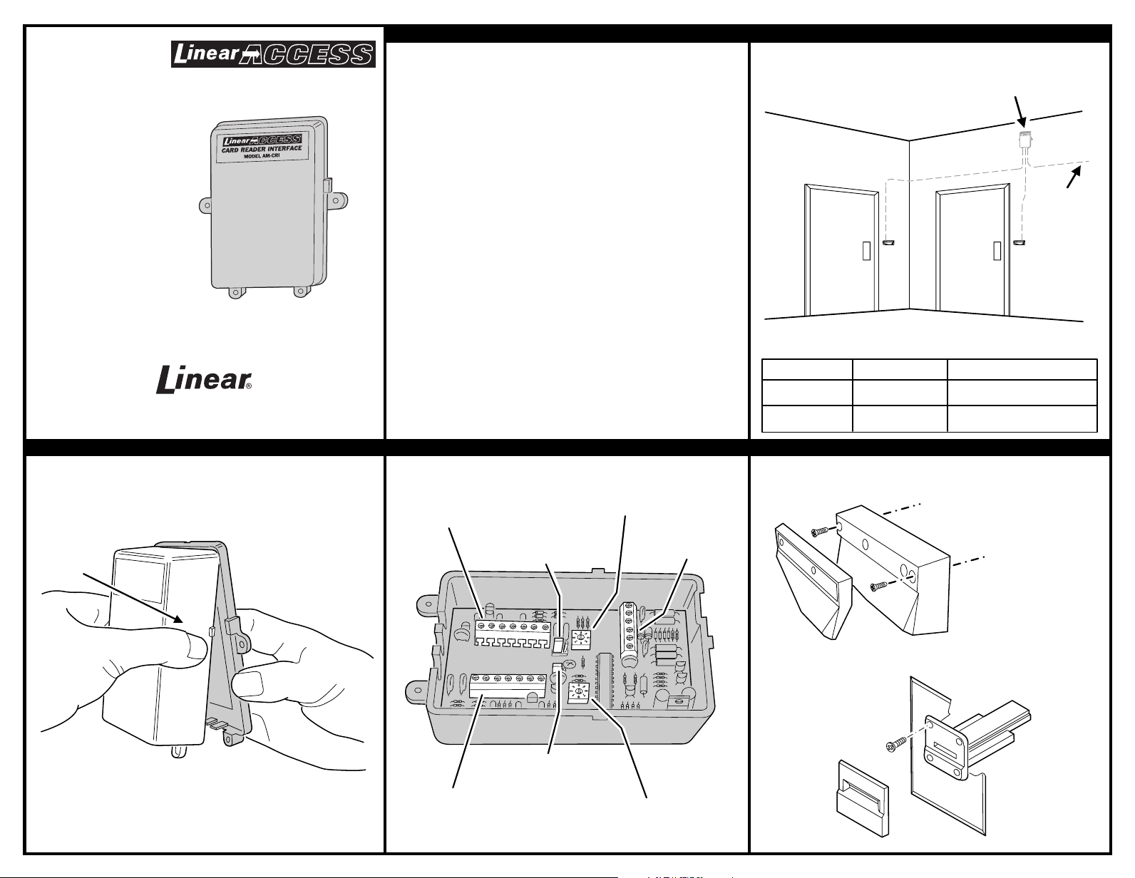
1. TYPICAL INSTALLATION
2. OPEN CASE 3. LOCATE COMPONENTS 4. MOUNT READERS
(760) 438-7000 • FAX (760) 438-7043
USA & Canada (800) 421-1587 & (800) 392-0123
Toll Free FAX (800) 468-1340
www.linearcorp.com
SQUEEZE
SIDES
TOGETHER
SEPARATE
CASE
POWER & DATA
TERMINALS
(CONNECTS TO AM/II)
READER "A"
TERMINALS
READER "B"
TERMINALS
READER "A"
POWER JUMPER
READER "B"
POWER JUMPER
READER "A"
DEVICE ADDRESS
SELECTOR
READER "B"
DEVICE ADDRESS
SELECTOR
MOUNT READER(S)
PER MANUFACTURER'S
SPECIFICATIONS
AM-CRI
INTERFACE
ONE OR TWO READERS
CAN BE USED
EACH AM-CRI EQUALS 25 LOAD UNITS
CABLE LENGTH FORMULA FOR EACH AM-CRI USED IN SYSTEM
CABLE RUN CABLE TYPE FORMULA
120 FEET MAXIMUM
BELDEN 9931 (24 AWG)
(INSIDE WALL)
FEET x LOAD UNITS < 3,000 MAXIMUM
CABLE TO AM/II
(SEE FORMULA)
HOMERUN
WIRE EACH
AM-CRI
TO AM/II
400 FEET MAXIMUM
WEICO 9405 (20 AWG)
FEET x LOAD UNITS < 10,000 MAXIMUM
Page 2
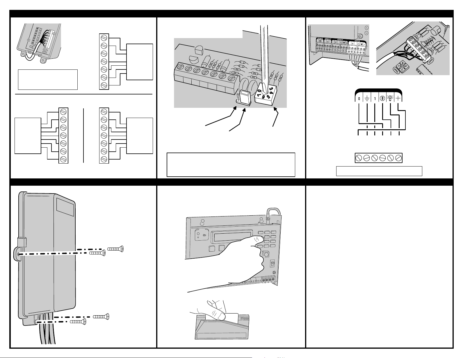
5. CONNECT READERS TO AM-CRI 6. SET DEVICE ADDRESS AND POWER JUMPERS 7. CONNECT AM-CRI TO AM/II
8. CLOSE CASE AND MOUNT UNIT 9. PROGRAM AND TEST LINEAR LIMITED WARRANTY
This Linear product is warranted against defects in material and workmanship for twelve
(12) months. The Warranty Expiration Date is labeled on the product.
This warranty
extends only to wholesale customers
who buy direct from Linear or through Linear’s
normal distribution channels.
Linear does not warrant this product to consumers.
Consumers should inquire from their selling dealer as to the nature of the dealer’s
warranty, if any.
There are no obligations or liabilities on the part of Linear
Corporation for consequential damages arising out of or in connection with use
or performance of this product or other indirect damages with respect to loss of
property, revenue, or profit, or cost of removal, installation, or reinstallation.
All
implied warranties, including implied warranties for merchantability and implied
warranties for fitness, are valid only until Warranty Expiration Date as labeled on the
product.
This Linear Corporation Warranty is in lieu of all other warranties express
or implied.
All products returned for warranty service require a Return Product Authorization
Number (RPA#). Contact Linear Technical Services at 1-800-421-1587 for an RPA#
and other important details.
Copyright © 2000 Linear Corporation 211845 D
NOTE:
REFER TO STEP 3 ILLUSTRATION
FOR COMPONENT LOCATIONS
8 VOLT POWER
TO READER
5 VOLT POWER
TO READER
SET READER
POWER JUMPER
SET DEVICE
ADDRESS
SELECTOR
SET TO POSITION 1-6
(MUST BE DIFFERENT
FROM OTHER READER)
REMOVE JUMPER WHEN
USING EXTERNAL POWER
NOTE:
WHEN USING ONE READER WITHOUT A "HOLD" LINE,
CONNECT IT TO READER "B" TERMINALS AND SET
READER "A" DEVICE ADDRESS SELECTOR TO "0"
SET UNUSED READER
ADDRESS TO "0"
AM/II
B
O
1
O
O
O
1
1
1
B
PWR
GND
DAT1
DATO
DVAL
CLK
AM/II
TERMINALS
(RED)
(BLK)
(GRN)
(WHT)
(BLU)
(ORG/YEL)
READER IN
AM-CRI
TERMINALS
AM-CRI
USE CABLE FORMULA
TO DETERMINE CABLE
TYPE AND MAXIMUM
LENGTH
NOTE: AM/II MUST BE TURNED OFF BEFORE
MAKING ANY WIRING CONNECTIONS
DAT1
DAT0
LED2
LED1
HOLD
GND
PWR
DAT1
DAT0
LED2
LED1
HOLD
GND
PWR
READER "A"
TERMINALS
READER "B"
TERMINALS
READER "A" READER "B"
REFER TO READER MANUFACTURER'S SPECIFICATIONS
FOR READER WIRE COLOR AND HOOK UP DETAILS
DAT1
DAT0
LED2
LED1
HOLD
GND
PWR
READER "B"
TERMINALS
READER "B"
SINGLE
READER
HOOKUP
W/O HOLD
TWO READER
HOOKUP
WITH HOLD
LED1- ON
DURING
STANDBY
LED2- ON
DURING
ACCESS
USE FOUR SCREWS
TO MOUNT THE
AM-CRI
SNAP CASE TOGETHER
SLIDE CARD THROUGH
READER AND VERIFY
THAT SYSTEM FUNCTIONS
PROGRAM THE AM/II TO CONFIGURE
THE READER(S) AND SET THE
BLOCK CARD CODES
REFER TO THE AM/II
PROGRAMMING INSTRUCTIONS
FOR DETAILS
 Loading...