

Page 1
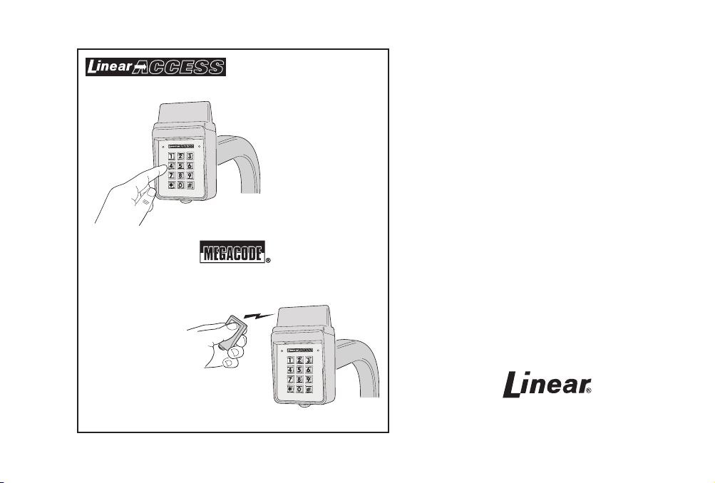
AKR-1
Digital Keyless Entry System
With Built-in Wireless Receiver
Installation and Programming Instructions
(760) 438-7000 • FAX (760) 438-7043
USA & Canada (800) 421-1587 & (800) 392-0123
Toll Free FAX (800) 468-1340
www.linearcorp.com
Page 2

CONTENTS
FEATURES . . . . . . . . . . . . . . . . . . . . . . . . . . . . . . . . . . . . . . . . . . . 1
INSTALLATION . . . . . . . . . . . . . . . . . . . . . . . . . . . . . . . . . . . . . . . . 1
COMPONENT LOCATIONS. . . . . . . . . . . . . . . . . . . . . . . . . . . . . . . . 2
WIRING DIAGRAM . . . . . . . . . . . . . . . . . . . . . . . . . . . . . . . . . . . . 3
FACTORY DEFAULTS . . . . . . . . . . . . . . . . . . . . . . . . . . . . . . . . . . . . 7
BASIC PROGRAMMING . . . . . . . . . . . . . . . . . . . . . . . . . . . . . . . . . 7
PROGRAMMING OPTIONS . . . . . . . . . . . . . . . . . . . . . . . . . . . . . . . 8
RADIO PROGRAMMING. . . . . . . . . . . . . . . . . . . . . . . . . . . . . . . . 11
AKR-1 OPERATION . . . . . . . . . . . . . . . . . . . . . . . . . . . . . . . . . . . 15
MGT OBSTACLE TRANSMITTER OPERATION . . . . . . . . . . . . . . . . . . 16
RADIO TEST MODE. . . . . . . . . . . . . . . . . . . . . . . . . . . . . . . . . . . . 16
SPECIFICATIONS. . . . . . . . . . . . . . . . . . . . . . . . . . . . . . . . . . . . . . 17
LINEAR LIMITED WARRANTY . . . . . . . . . . . . . . . . . . . . . . . . . . . . 17
IMPORTANT !!! . . . . . . . . . . . . . . . . . . . . . . . . . . . . . . . . . . . . . . 18
FCC NOTICE . . . . . . . . . . . . . . . . . . . . . . . . . . . . . . . . . . . . . . . . . 18
PRODUCT DESCRIPTION
Linear’s AKR-1 is a digital keyless entry system with a built-in radio receiver
designed for access control applications. The keypad is housed in a rugged, cast
aluminum enclosure that can be mounted to a pedestal or bolted directly to a wall.
The die-cast keys have bright, easy-to-read yellow graphics.
Up to 480 entry codes, from 1 to 6 digits in length, can be programmed. They
can activate either, or both, of the relay outputs. Relay #1 has a 5 Amp capacity.
Relay #2 has a 1 Amp capacity.
Up to four sets of block coded MegaCode
total) can be used to gain access through the AKR-1’s built-in radio receiver.
Each transmitter can be individually suspended or re-activated. Four facility codes
®
transmitters (up to 480 transmitters
can be programmed to identify each block of transmitters. A Radio Test Mode is
provided for testing transmitters and detecting radio interference. Programming of
individual (non-block coded) transmitters is not supported by the AKR-1.
Linear’s Model MGT safety edge transmitter is compatible with the AKR-1. This
supervised transmitter is used to detect and transmit obstacle events to the AKR-1
receiver. Obstacle signals from an MGT transmitter will activate Relay #2.
Two indicators show the status of the entry system. The left indicator lights red to
indicate power, then turns green when access is granted. The right indicator lights
yellow when the keypad is in “lockout” condition (from too many incorrect code
entries). The keypad’s courtesy light illuminates the keys for two minutes after any
key is pressed. An internal sounder beeps when each key is pressed and when a
transmitter is granted access. An internal jumper sets the sounder volume high or
low.
The DOOR SENSE/INHIBIT input can be used two ways. If programmed for
“door sense”, a switch on the door detects forced entry or door ajar situations. If
programmed for “inhibit”, the input can be wired to a “service” switch or automatic
timer that will disable the Relay #1 when required.
The REQUEST-TO-ENTER input can be wired to a pushbutton or fi re access
keyswitch to provide codeless entry for authorized personnel.
The “anti-passback” feature prevents using the same code or the same transmitter
again before the programmed time elapses.
The ALARM SHUNT output activates when access is granted. This output can be
wired to shunt alarm contacts on the access door/gate to prevent triggering of an
alarm when authorized access occurs.
Two solid state outputs, capable of switching 100 mA to common, are programmable
to signal forced entry, door ajar, lockout, alarm circuit shunting, request-to-enter,
and keypad active conditions.
The AKR-1 is powered from a 12-24 Volt AC or DC source. Power can be obtained
from the access device or a separate power supply. The EEPROM memory retains
all entry codes, transmitter information, and programming, even without power. An
internal jumper is provided to reset the master code.
Page 3
FEATURES
✓ KEYPAD PROGRAMMABLE
✓ 480 ENTRY CODE CAPACITY
✓ 480 TRANSMITTER CAPACITY
✓ SUPPORTS 4 BLOCKS OF TRANSMITTERS WITH 4 FACILITY CODES
✓ WEATHER-PROOF, TAMPER-RESISTANT RADIO ANTENNA
✓ SUPPORTS 1 MODEL MGT SAFETY EDGE TRANSMITTER
✓ 1-6 DIGIT ENTRY CODE LENGTH
✓ 4 INDEPENDENT OUTPUTS (TIMED/TOGGLED)
✓ 4 INDEPENDENT TIMERS
✓ EACH ENTRY CODE CAN BE PROGRAMMED TO ACTIVATE EITHER OR BOTH RELAYS
✓ RELAY CONTACTS ARE FORM “C” (N.O. & N.C)
✓ SOLID STATE OUTPUTS ARE OPEN COLLECTOR (SWITCH-TO-COMMON)
✓ TWO STATUS INDICATORS
✓ COURTESY LAMP
✓ PIEZO SOUNDER
✓ TIMED ANTI-PASSBACK (LAST 3 VALID ENTRIES)
✓ KEYPAD LOCKOUT
✓ TACTILE KEY FEEL
✓ DOOR SENSE INPUT
✓ INHIBIT INPUT
✓ REQUEST-TO-ENTER INPUT
INSTALLATION
To avoid damage to the unit from static discharges, connect the
EARTH GROUND terminal to a good earth grounding point. Suggested
wiring size is 18 AWG for earth ground and power (up to 500 feet
of 18 AWG wire can be run for power, use larger wire for longer
runs). Use 22 AWG or larger (depending on the load) for all other
connections.
✦ CAUTION: If the unit is AC powered, and one side of
the power transformer secondary is connected to earth
ground, connect the grounded side to the “-” power
terminal of the unit.
Select a location for the keypad. For door access control installations,
mount the keypad near the controlled door. For gate control
installations, mount the keypad in clear view of the gate, but far
enough from the gate so the user cannot touch the gate from the
keypad.
★ WARNING: TO AVOID SERIOUS INJURY OR DEATH,
MAKE SURE THAT THE UNIT IS FAR ENOUGH FROM
THE GATE SO THAT THE USER CANNOT TOUCH THE
GATE WHILE OPERATING THE KEYPAD. HOWEVER,
THE GATE MUST BE FULLY VISIBLE FROM THE
KEYPAD.
1
Page 4
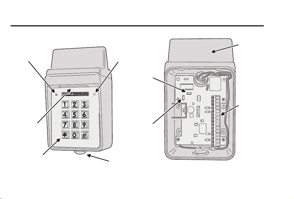
COMPONENT LOCATIONS
RED/GREEN
POWER/ACCESS
INDICATOR
YELLOW
"LOCKOUT"
INDICATOR
JUMPER JP2
REMOVE
TO RESET
MASTER CODE
ANTENNA
(HIDDEN)
TERMINAL
BLOCK
NIGHT
LIGHT
TACTILE
KEYPAD
JUMPER JP1
REMOVE TO
REDUCE
BEEPER SOUND
KEYLOCK
Figure 1. Component Locations
2
Page 5
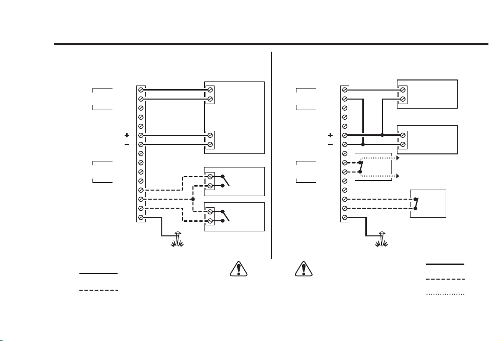
WIRING DIAGRAM
TYPICAL DOOR INSTALLATION WIRINGTYPICAL GATE INSTALLATION WIRING
AKR-1 TERMINALS
MAIN
RELAY
AUXILIARY
RELAY
REQUEST-TO-ENTER
NOTE:
TERMINAL 14 SET FOR INHIBIT
REQUIRED WIRING
OPTIONAL WIRING
N.O.
COMMON
N.C.
OUTPUT #3
OUTPUT #4
DC OR AC POWER
COMMON
N.O.
COMMON
N.C.
COMMON
INHIBIT
EARTH GROUND
AKR-1 TERMINALS
TO ALARM
SYSTEM
ELECTRIC
DOOR
STRIKE
POWER
SUPPLY
DOOR
SWITCH
REQUIRED WIRING
OPTIONAL WIRING
OTHER WIRING
1
2
3
4
5
6
7
8
9
10
11
12
13
14
15
GROUND
STAKE
OPEN
OPERATOR
TRANSFORMER
ISOLATED
AUXILIARY
POWER
ACCESS
INHIBIT
TIMER
GATE
FIRE
MAIN
RELAY
DC OR AC POWER
AUXILIARY
RELAY
REQUEST-TO-ENTER
DOOR SENSE
EARTH GROUND
NOTES:
1. ALARM SHUNT SET FOR AUXILIARY RELAY
2. TERMINAL 14 SET FOR DOOR SENSE
COMMON
OUTPUT #3
OUTPUT #4
COMMON
COMMON
COMMON
1
N.O.
2
3
N.C.
4
5
6
7
8
9
N.O.
10
11
N.C.
12
13
14
15
ALARM
CONTACT
GROUND
STAKE
CAUTION
AND ONE SIDE OF THE POWER TRANSFORMER SECONDARY
IS CONNECTED TO EARTH GROUND, CONNECT THE GROUNDED
IF THE UNIT IS AC POWERED,
SIDE TO THE "-" POWER TERMINAL OF THE UNIT.
3
Page 6
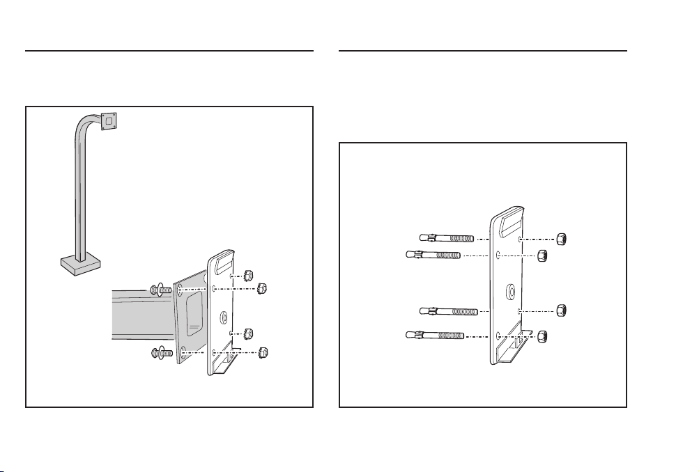
Pedestal Mounting
The AKR-1 keypad can be mounted on a standard pedestal.
❑ Use four security bolts and locking nuts to secure the
keypad’s backplate to the pedestal (see Figure 3).
Wall Mounting
The AKR-1 keypad can be mounted directly to a wall or fl at
surface.
❑ Use the appropriate fasteners to secure the keypad’s
backplate to the mounting surface.
❑ When mounting the keypad to a concrete wall, use concrete
wedge anchors or molly anchors (see Figure 4).
PEDESTAL
MOUNT BACKPLATE WITH
SECURITY BOLTS AND LOCKNUTS
WALL MOUNTING
USE CONCRETE
WEDGE ANCHORS
OR MOLLY ANCHORS
Figure 4. Wall Mounting Keypad BackplateFigure 3. Pedestal Mounting Keypad Backplate
4
Page 7

Gate Control
Refer to Figure 5 for an outline of a typical gate installation.
❑ Route four wires between the gate and the keypad (two for
power, two for control).
❑ Connect the gate operator’s auxiliary or radio power output
terminals to the keypads POWER input terminals (observe
wiring polarity).
❑ Connect the gate operator’s OPEN terminals to the keypad’s
Relay #1 COMMON & N.O. terminals.
☞ NOTE: For operator wiring specifi cs, refer to the gate
operator’s wiring diagram.
❑ If a request-to-enter pushbutton or fi re access keyswitch is
going to be used, route two wires from the keypad to the
normally open switch. Connect the wires to the normally
open switch and to the keypad’s REQUEST-TO-ENTER and
COMMON terminals.
❑ If an inhibit switch or timer is going to be used, route two
wires from the keypad to the inhibit switch or timer relay.
Connect the inhibit switch/timer terminals to the keypad’s
INHIBIT and COMMON terminals.
☞ NOTE: If the INHIBIT input is going to be used, it must be
programmed to select that input type. See the Programming
Options section of this manual
AKR-1
KEYPAD
2 WIRES FOR
FIRE
ACCESS
KEYSWITCH
2 WIRES FROM AKR-1
TO TRIGGER GATE OPEN
REQUEST-TO-ENTER
Figure 5. Gate Installation
GATE
OPERATOR
(BEHIND GATE)
2 WIRES FROM OPERATOR
FOR AKR-1 POWER
5
Page 8
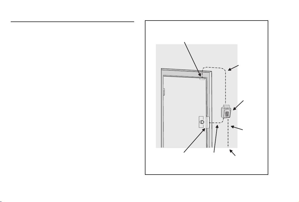
Door Control
❑ Install a low voltage electric door strike for unlocking the
door.
❑ Choose a location for the power supply or transformer.
❑ Route two wires between the power supply and the keypad.
Connect the power supply’s output terminals to the keypad’s
POWER input terminals (observe wiring polarity).
❑ Route two wires between the door strike and the keypad.
Connect one of the door strike wires to the keypad’s
Relay #1 N.O. terminal. Connect the other door strike wire
to the keypad’s POWER + terminal. Connect a wire between
the keypad’s POWER - terminal and the Relay #1 COMMON
terminal.
❑ If a request-to-enter pushbutton or fi re access keyswitch is
going to be used, route two wires from the keypad to the
normally open switch. Connect the wires to the normally
open switch and to the keypad’s REQUEST-TO-ENTER and
COMMON terminals.
❑ To use the door sense feature to detect forced entry or door
ajar conditions, install a normally closed door switch on the
door and route two wires from the switch to the keypad.
Connect the door switch to the keypad’s DOOR SENSE and
COMMON terminals.
❑ If an inhibit switch or timer is going to be used, route two
wires from the switch or timer to the keypad. Connect the
inhibit switch/timer terminals to the keypad’s INHIBIT and
COMMON terminals.
☞ NOTE: Either door sense or inhibit can be used. Both
features cannot be used at the same time.
6
DOOR
SENSE
SWITCH
ELECTRIC
DOOR
STRIKE
2 WIRES
FOR DOOR
STRIKE
Figure 6. Door Installation
2 WIRES
FOR DOOR
SENSE
AKR-1
KEYPAD
2 WIRES
FOR
POWER
FROM
POWER
SUPPLY
Page 9

FACTORY DEFAULTS
MASTER PROGRAMMING CODE . . . . . . . . . . . . . . . . . . . . . . . . . . . . . . . . . . . . . . . 123456
ENTRY CODE LENGTH . . . . . . . . . . . . . . . . . . . . . . . . . . . . . . . . . . . . . . . . . . . . . 4 DIGITS
REQUEST-TO-ENTER OUTPUT . . . . . . . . . . . . . . . . . . . . . . . . . . . . . . . . . . . . . . . . RELAY #1
ALARM SHUNT OUTPUT . . . . . . . . . . . . . . . . . . . . . . . . . . . . . . . . . . . . . . . . . . DISABLED
FORCED ENTRY OUTPUT . . . . . . . . . . . . . . . . . . . . . . . . . . . . . . . . . . . . . . . . . OUTPUT #3
DOOR AJAR OUTPUT. . . . . . . . . . . . . . . . . . . . . . . . . . . . . . . . . . . . . . . . . . . . OUTPUT #4
RELAY #1 ON TIME. . . . . . . . . . . . . . . . . . . . . . . . . . . . . . . . . . . . . . . . . . . . . 2 SECONDS
RELAY #2 ON TIME. . . . . . . . . . . . . . . . . . . . . . . . . . . . . . . . . . . . . . . . . . . . . 2 SECONDS
SOLID STATE OUTPUT #3 ON TIME. . . . . . . . . . . . . . . . . . . . . . . . . . . . . . . . . . 2 SECONDS
SOLID STATE OUTPUT #4 ON TIME. . . . . . . . . . . . . . . . . . . . . . . . . . . . . . . . . . 2 SECONDS
DOOR SENSE/INHIBIT INPUT . . . . . . . . . . . . . . . . . . . . . . . . . . . . . . . . . . . . DOOR SENSE
KEYPAD LOCKOUT OUTPUT . . . . . . . . . . . . . . . . . . . . . . . . . . . . . . . . . . . . . . . . DISABLED
KEYPAD ACTIVE OUTPUT . . . . . . . . . . . . . . . . . . . . . . . . . . . . . . . . . . . . . . . . . . DISABLED
BEEPER SOUNDS WHEN KEY PRESSED . . . . . . . . . . . . . . . . . . . . . . . . . . . . . . . . . . . . . YES
BEEPER SOUNDS DURING RELAY #1 . . . . . . . . . . . . . . . . . . . . . . . . . . . . . . . . . . . . . . NO
BEEPER SOUNDS DURING RELAY #2 . . . . . . . . . . . . . . . . . . . . . . . . . . . . . . . . . . . . . . NO
BEEPER SOUNDS DURING OUTPUT #3 . . . . . . . . . . . . . . . . . . . . . . . . . . . . . . . . . . . . . NO
BEEPER SOUNDS DURING OUTPUT #4 . . . . . . . . . . . . . . . . . . . . . . . . . . . . . . . . . . . . . NO
KEYPAD LOCKOUT COUNT. . . . . . . . . . . . . . . . . . . . . . . . . . . . . 3 TRIES BEFORE LOCKOUT
ANTI-PASSBACK TIME . . . . . . . . . . . . . . . . . . . . . . . . . . . . . . . . . . . . . NO ANTI-PASSBACK
TRANSMITTER LEFT BUTTON ACTIVATES . . . . . . . . . . . . . . . . . . . . . . . . . . . . . . . . RELAY #1
TRANSMITTER RIGHT BUTTON ACTIVATES. . . . . . . . . . . . . . . . . . . . . . . . . . . . . . . RELAY #2
TRANSMITTER TOP BUTTON ACTIVATES. . . . . . . . . . . . . . . . . . . . . . . . . . . . . . . . . . . NONE
TRANSMITTER LOWER LEFT BUTTON ACTIVATES . . . . . . . . . . . . . . . . . . . . . . . . . . . . NONE
TRANSMITTER LOWER RIGHT BUTTON ACTIVATES . . . . . . . . . . . . . . . . . . . . . . . . . . . NONE
BASIC PROGRAMMING
When the AKR-1 is in Programming Mode, both indicators will turn
off until programming begins. After a programming option number is
entered the yellow indicator will blink. This shows that the AKR-1 is
ready to accept the new programming data. After the new data entry
is complete, the green indicator will light while the data is being
stored.The red indicator will light if any programming data is entered
incorrectly, and the command will have to be fully re-entered.
Entering Programming Mode
The 6-digit Master Programming Code (default = 123456) is used to enter
Programming Mode.
Press: # 9 # Master Code
Master Code = the current 6-digit Master Programming Code
Exiting Programming Mode
Press: * * #
The red indicator will light when Programming Mode is exited.
☞ NOTE: The AKR-1 will automatically exit Programming Mode after two minutes of inactivity.
Re-entering a Command After a Mistake
If the red indicator lights, signaling an incorrect entry, or an incorrect key is pressed
during programming, to clear the keypad and re-enter the command:
Press: * 9 #
Setting Entr y Code Length Default: 4 digits
Press: 0 3 # Length #
☞ NOTE: If the Entry Code Length is going to be changed from the factory default of four
digits, make this change fi rst, before programming any entry codes.
Length = 1 - 6 for entry code length
7
Page 10

Adding a New Entry Code
Press: 0 1 # Code # Code # Relay #
Code = The new entry code: 1-999999, depending on code length
Relay = Relay output entry code will activate:
The yellow indicator will fl ash quickly while the AKR-1 searches its memory for
available space and duplicate entries. The green indicator will light when the new
code is stored.
If the new entry code chosen is already being used for another entry code, the red
indicator will light. A new unique code needs to be entered.
☞ NOTE: Leading zeros (zeros before the code number, i.e. 0001) do not need to be entered
when programming a new entry code. The AKR-1 will internally add any zeros to fi ll all
digits determined by the entry code length setting. Leading zeros will have to be entered by
the user when entering their code to gain access.
Erasing a Single Entry Code
1 = Relay #1 2 = Relay #2 3 = Both Relays
Press: 0 2 # Code # Code #
The yellow indicator will fl ash quickly while the AKR-1 searches its memory for the
code to erase. The green indicator will light when the code is erased.
Erasing All Entry Codes
★ WARNING: Performing this command will remove all
entry codes from the memory.
☞ NOTE: The green indicator will light while the memory is being erased. This may take up
to 15 seconds.
Changing the 6-Digit Master Programming Code
Code = The entry code to delete.
Press: 9 7 # 0 0 0 0 0 0 # 0 0 0 0 0 0 #
Press: 9 8 # Master Code # Master Code #
Master Code = The new 6-digit Master Programming Code
New master code: _____________________
8
PROGRAMMING OPTIONS
There are several AKR-1 programming options. For most installations, the factory
set default options are suffi cient. The keypad must be in Programming Mode to
make these changes.
Programming AKR-1 to Hold the Output
Linear’s AccessKey products have a programmable “Toggle Mode” available for
each relay and solid-state output. When an output is programmed for Toggle Mode,
the output alternates from OFF to ON or from ON to OFF each time it is activated.
The rules for a toggle output are:
• If the output is OFF, it will turn ON and stay on until the next activation.
• If the output is ON, it will turn OFF and stay off until the next activation.
Typical Programming
With the unit in Program Mode, set the Auxiliary Relay (Relay #2) output to Toggle
Mode using the following keystrokes:
Press: 2 2 # 9 9 #
Program all normal entry codes to use the Main Relay (Relay #1), and only
Relay #1 as the output relay. Program the code(s) that you want to use to hold the
output for an indefi nite period to the Auxiliary Relay (Relay #2). See the following
example that sets entry codes 1234 for normal and 5678 for toggle operation.
NORMAL
ENTRY CODE
TOGGLE
ENTRY CODE
22 = Programming Step; 99 = Toggle Mode
1234
Press: 0 1 # 1 2 3 4 # 1 2 3 4 # 1 #
01 = Programming Step; 1234 = Entry Code;
1 = Main Relay
5678
Press: 0 1 # 5 6 7 8 # 5 6 7 8 # 2 #
01 = Programming Step; 5678 = Entry Code;
2 = Auxiliary Relay
Page 11

Typical Toggle Mode Wiring
For devices triggered by a normally open circuit, wire the contacts of the Main
and Auxiliary Relays in parallel (see the Figure below). Either relay will be able to
trigger the access device. Entry codes programmed for the Auxiliary Relay will be
able to hold the output on.
MAIN
AKR-1
OUTPUTS
Select Door Sense or Inhibit Input Default: Door Sense
The input on Terminal #14 can be programmed for DOOR SENSE or INHIBIT.
RELAY
AUXILIARY
RELAY
N.O.
COMMON
N.C.
N.O.
COMMON
N.C.
ACCESS
DEVICE
EITHER RELAY CAN TRIGGER
THE ACCESS DEVICE
Press: 1 0 # Input#
When programmed for DOOR SENSE, if an open condition on the input occurs
before access is granted (with an entry code, transmitter or with the request-toenter input) a FORCED ENTRY output will occur. If an open condition remains 60
seconds after a relay activation for access, a DOOR AJAR output will occur.
When programmed for INHIBIT, a closed condition on the input will prevent
Relay #1 from activating when access is requested (with an entry code or
transmitter). This mode is typically used with an external timer to disable the
access device at certain times.
Input = 0 for Door Sense, = 1 for Inhibit
Select Forced Entry Output Default: Output #3
Sets which output activates if the DOOR SENSE input opens before access is
granted. This output is not timed.
Press: 1 1 # Output #
1 = Relay #1 2 = Relay #2 3 = Output #3 4 = Output #4 0 = No Output
Select Door Ajar Output Default: Output #4
Sets which output activates if the DOOR SENSE input stays open 60 seconds after
access is granted. This output is not timed.
Output = Output to Activate (0-4)
Press: 1 2 # Output #
1 = Relay #1 2 = Relay #2 3 = Output #3 4 = Output #4 0 = No Output
Select Keypad Lockout Output Default: No Output
Sets which output activates when the keypad is “locked out” after too many
incorrect entry code attempts. The lockout time is 60 seconds.
Output = Output to Activate (0-4)
Press: 1 3 # Output #
1 = Relay #1 2 = Relay #2 3 = Output #3 4 = Output #4 0 = No Output
Select Keypad Active Output Default: No Output
Sets which output activates when any keys are pressed. This output is timed. If
toggle mode is selected for the output, the timer value defaults to 2 seconds.
Output = Output to Activate (0-4)
Press: 1 4 # Output #
1 = Relay #1 2 = Relay #2 3 = Output #3 4 = Output #4 0 = No Output
Output = Output to Activate (0-4)
9
Page 12

Select Alarm Shunt Output Default: No Output
Sets which output activates during the time access is granted. (Use this output
to shunt alarm contacts attached to the access door.) This output may be timed
or toggled.
Press: 1 5 # Output #
1 = Relay #1 2 = Relay #2 3 = Output #3, 4 = Output #4 0 = No Output
Select Request-to-Enter Output Default: Relay #1
Sets which output activates when the Request-to-Enter input is grounded. This
output may be timed or toggled.
Output = Output to Activate (0-4)
Press: 1 6 # Output #
1 = Relay #1 2 = Relay #2 3 = Output #3 4 = Output #4 0 = No Output
Relay #1 On-time Default: 2 Seconds
Sets the length of time Relay #1 activates when triggered.
Output = Output to Activate (0-4)
Press: 2 1 # Seconds #
Seconds = Output time in seconds (0-60), 99 = Toggle mode
Relay #2 On-time Default: 2 Seconds
Sets the length of time Relay #2 activates when triggered.
Press: 2 2 # Seconds #
Seconds = Output time in seconds (0-60), 99 = Toggle mode
Solid-state Output #3 On-time Default: 2 Seconds
Sets the length of time Output #3 activates when triggered.
Press: 2 3 # Seconds #
Seconds = Output time in seconds (0-60), 99 = Toggle mode
Solid-state Output #4 On-time Default: 2 Seconds
Sets the length of time Output #4 activates when triggered.
10
Seconds = Output time in seconds (0-60), 99 = Toggle mode
Beep Sounds on Keystrokes Default: Yes
Selects whether or not the keypad beeps as each key is pressed.
Press: 4 0 # Sound #
Press: 2 4 # Seconds #
Sound = 1 for Yes, = 0 for No
Beep Sounds During Relay #1 Default: No
Selects whether or not the keypad beeps during Relay #1 activation.
Press: 4 1 # Sound #
Sound = 1 for Yes, = 0 for No
Beep Sounds During Relay #2 Default: No
Selects whether or not the keypad beeps during Relay #2 activation.
Press: 4 2 # Sound #
Sound = 1 for Yes, = 0 for No
Beep Sounds During Output #3 Default: No
Selects whether or not the keypad beeps during Output #3 activation.
Press: 4 3 # Sound #
Sound = 1 for Yes, = 0 for No
Beep Sounds During Output #4 Default: No
Selects whether or not the keypad beeps during Output #4 activation.
Press: 4 4 # Sound #
Sound = 1 for Yes, = 0 for No
Keypad Lockout Count Default: 3 Tries
Sets the number of incorrect entry code attempts allowed before the keypad “locks
out”.
Press: 5 0 # Attempts #
Attempts = Number of attempts before lockout (2-7)
Page 13

Anti-passback Time Default: No Anti-passback
Sets the length of time an entry code or transmitter will not function after it is
used.
Press: 5 1 # Minutes #
Minutes = Time in Minutes (1-4), 0 = No Anti-passback
RADIO PROGRAMMING
The following programming steps are used to add, remove, suspend,
and confi gure block coded transmitters used with the AKR-1.
Programming of individual (non-block coded) transmitters is
not supported by the AKR-1.
Add Transmitter Block(s)
Sets the starting and ending TX ID numbers for up to four blocks of pre-programmed
transmitters. Enter this command up to four times
blocks one, two, three, and four. Up to 480 transmitters total, distributed in any
quantity between the blocks, can be added to the AKR-1’s memory.
to select TX IDs for transmitter
Press: 8 0 # Start ID # End ID #
Start ID = 1-65535
End ID = 1-65535
Erase Transmitter Block(s)
This command will erase all
be erased individually. Single transmitters can be suspended from operation using
the Suspend/Reactivate command.
transmitters from memory. Transmitter blocks cannot
Press: 9 1 # 0 0 0 0 0 0 # 0 0 0 0 0 0 #
Suspend/Reactivate an Individual Transmitter
This command suspends (prevents transmitter from being used), or reactivates
(un-suspends) the designated transmitter. NOTE: This command will effect the fi rst
occurrence of the TX ID in memory. If, by rare chance, duplicate TX ID numbers
occur in different transmitter blocks, contact Linear Technical Services for details
on how to suspend/reactivate individual transmitters.
Press: 9 0 # TX ID # Status #
Status = 0 for Suspend, = 1 for Reactivate
Selecting the Facility Codes Default: Ignore Facility Code
Facility Codes increase security by requiring the Facility Code as well the TX ID
code to match before access is granted. Up to four Facility Codes can be entered.
The Facility Code number is labeled on the box of block coded transmitters. Enter
the Facility Code number (1-15) for each transmitter block added to the AKR-1.
TX ID = 1-65535
Press: 6 0 # Location # Code #
Code = Facility Code number (1-15), 0 = Ignore transmitter Facility Codes
Add MGT Obstacle Transmitter
Programs a Model MGT obstacle transmitter into the AKR-1. Locate the MGT
ID and facility codes on a label inside the MGT enclosure. See previous section
(Selecting the facility codes) to enter the MGT facility code. Refer to the MGT
Obstacle Transmitter Operation section of this manual and the MGT Installation
Instructions for details on MGT transmitter operation. To enter MGT ID:
Location = Facility Code Memory Location (1-4)
Press: 9 9 # ID # ID #
ID = 1 - 65535
Erase MGT Obstacle Transmitter
Removes a Model MGT obstacle transmitter from the AKR-1 memory.
Press: 9 5 # 0 0 0 0 0 0 # 0 0 0 0 0 0 #
Select Left Button Output Default: Relay #1
Sets which relay output activates when a transmitter’s left button is pressed. This
setting effects all transmitters used with the AKR-1. See Figure 7 for transmitter
button designations for various models.
Press: 7 1 # Output #
1 = Relay #1 2 = Relay #2 3 = Both Relays 0 = No Output
Output = Output to Activate (0-3)
11
Page 14

BOTTOM-LEFT
BUTTON
12
BOTH
FUNCTION
AS LEFT
BUTTON
ACT-31
SINGLE-CHANNEL
MDT
LEFT
BUTTON
MDT-2
TOP
BUTTON
RIGHT
BUTTON
BOTTOM-RIGHT
ACT-34
FOUR-CHANNEL
TRANSMITTER
BUTTON
LEFT
BUTTON
BUTTON
RIGHT
TRANSMITTERS
BUTTON
THREE-CHANNEL
TRANSMITTERS
LEFT
BUTTON
BOTTOM-LEFT
BUTTON
MDT-4
Figure 7. Transmitter Button Designations
LEFT
BUTTON
BOTH EQUALS
TOP BUTTON
LEFT
TOP
BUTTON
LEFT
BUTTON
ACT-21
RIGHT
BUTTON
RIGHT
BUTTON
BOTTOM-RIGHT
BUTTON
FIVE-CHANNEL
TRANSMITTER
ACT-22
Select Right Button Output Default: Relay #2
Sets which relay output activates when a transmitter’s right button is pressed. This
setting effects all transmitters used with the AKR-1. See Figure 7 for transmitter
button designations for various models.
Press: 7 2 # Output #
1 = Relay #1 2 = Relay #2 3 = Both Relays 0 = No Output
Select Top Button Output Default: No Output
Sets which relay output activates when a transmitter’s top button is pressed. This
setting effects all transmitters used with the AKR-1. See Figure 7 for transmitter
button designations for various models.
Output = Output to Activate (0-3)
Press: 7 3 # Output #
1 = Relay #1 2 = Relay #2 3 = Both Relays 0 = No Output
Select Bottom-left But ton Output Default: No Output
Sets which relay output activates when a transmitter’s bottom-left button is
pressed. This setting effects all transmitters used with the AKR-1. See Figure 7 for
transmitter button designations for various models.
Output = Output to Activate (0-3)
Press: 7 4 # Output #
1 = Relay #1 2 = Relay #2 3 = Both Relays 0 = No Output
Select Bottom-right Button Output Default: No Output
Sets which relay output activates when a transmitter’s bottom-right button is
pressed. This setting effects all transmitters used with the AKR-1. See Figure 7 for
transmitter button designations for various models.
Output = Output to Activate (0-3)
Press: 7 5 # Output #
1 = Relay #1 2 = Relay #2 3 = Both Relays 0 = No Output
Output = Output to Activate (0-3)
Page 15

Master Reset
✦ CAUTION: Performing a master reset will clear
the entire memory of the AKR-1 and return all
programmable options to the factory default values.
ALL ENTRY CODES AND TRANSMITTERS WILL BE
ERASED.
STEP 1 Disconnect power from the keypad.
STEP 2 Press and hold down the * and # keys.
STEP 3 Apply power to the keypad, continue holding the keys
down until the red indicator starts fl ashing.
STEP 4 Release the keys. The red and yellow indicators will
remain lit until the process is complete, then the yellow
indicator will go out.
Resetting the Master Code
STEP 1 Open the AKR-1 case.
STEP 2 Locate jumper JP2. This jumper is used to reset the
master code.
STEP 3 With power applied to the keypad, remove jumper JP2.
The keypad will begin to beep, signaling that the code
has been reset.
STEP 4 Replace jumper JP2. THE MASTER PROGRAMMING
CODE IS NOW 123456.
Solid State Outputs
The two solid state outputs (Output #3 & Output #4) can be
programmed to activate during various conditions. These outputs
can be used to activate indicators or sounders. See Figure 8 for
wiring examples using the solid state outputs.
AKR-1
POWER
OUTPUT #3
OUTPUT #4
OUTPUT #3
OUTPUT #4
EXAMPLE 2: OUTPUT #3 LIGHTS A LAMP POWERED FROM AN EXTERNAL
SOURCE, OUTPUT #4 TRIGGERS A NORMALLY OPEN ALARM PANEL ZONE
6
1K 9
LED
4
5
EXAMPLE 1: OUTPUT #3 LIGHTS AN LED,
OUTPUT #4 LIGHTS AN LED AND SOUNDS A BEEPER
4
LOW VOLTAGE
5
COMMON
8
GROUND
LAMP
END-OF-LINE
RESISTOR
1K 9
LED
POWER
SOURCE
ELECTRONIC
BEEPER
EACH
OUTPUT
100 mA
MAXIMUM
EACH
OUTPUT
100 mA
MAXIMUM
N.O. ZONE
ALARM PANEL
COMMON
Figure 8. Using Solid State Outputs
13
Page 16

Beeper Sound Level
The keypad’s beeper can be set to low or high level.
❑ If the keypad’s beeper is too loud for the keypad’s location,
remove jumper JP1 (see Figure 9).
REMOVE JUMPER JP1 TO
REDUCE THE BEEPER
VOLUME
Locking Keypad
After the installation is complete. Lock the keypad using the keylock
(see Figure 10).
HOOK KEYPAD
ONTO BACKPLATE
USE KEY TO
LOCK KEYPAD
14
Figure 9. Removing the Beeper Jumper
Figure 10. Locking the Keypad Case
Page 17

AKR-1 OPERATION
With Entry Code
❑ Users of the AKR-1 have up to 40 seconds to key in their
entry code.
❑ Up to eight seconds are allowed between each keystroke.
❑ All digits of the entry code must be entered. Example: If the
code is 0042, the user must enter “0 0 4 2”.
❑ If the wrong key is pressed, pressing the
keypad. The correct code can then be re-entered.
key will reset the
*
❑ After a correct code is entered, the red indicator will
turn green and the programmed relay will activate for the
programmed time.
❑ If the number of incorrect codes entered exceeds the
keypad lockout count, the yellow indicator will light,
indicating that the keypad is locked out. The lockout will
remain for one minute.
❑ After a valid code has been entered, it will be unusable until
the anti-passback time expires.
With Wireless Transmitter
❑ Activate a wireless transmitter within radio range (up to 300
feet) of the AKR-1.
❑ After a valid transmitter is decoded, the keypad will beep,
the red indicator will turn green, and the programmed relay
will activate for the programmed time.
❑ After a transmitter has been used to gain access, it will be
unusable until the anti-passback time expires.
RED LED TURNS
GREEN WHEN
ACCESS IS GRANTED
USERS HAVE UP TO
40 SECONDS TO ENTER
THEIR COMPLETE CODE
Figure 11. Operating the AKR-1
YELLOW LED WILL LIGHT
DURING KEYPAD LOCKOUT IF
TOO MANY INCORRECT CODES
ARE ENTERED
PRESS STAR KEY TO
RESET KEYPAD IF THE
WRONG KEY IS PRESSED
15
Page 18

MGT OBSTACLE TRANSMITTER OPERATION
One Model MGT obstacle transmitter can be programmed into the AKR-1. The
MGT is triggered with a safety edge contact and will activate the AKR-1 Relay #2
for the programmed length of time.
☞ NOTE: If an MGT transmitter is programmed, all other transmitters or entry code activations
programmed for Relay #2 will be blocked.
MGT Supervisory Mode
If an MGT supervisory condition occurs the AKR-1 will beep every 5 seconds. In
addition, all users will have to enter their entry code twice (within one minute), or
activate their transmitter twice (within ten seconds) to request access.
The MGT can monitor and produce three supervisory conditions: low battery, case
tamper/loop fault, and status. To determine the supervisory condition place the
AKR-1 in MGT supervisory mode, the same command is used to exit this mode:
Press the * , # , and “2” buttons
together for two seconds
While in MGT Supervisory Mode, the following conditions can be displayed:
Low Battery
If the transmitter detects a low battery, it will send a low battery supervisory report.
The keypad’s yellow indicator will blink.
Tamper/Loop Fault
If the transmitter case is opened or the safety edge contact becomes defective,
it will send a tamper/loop fault supervisory report. The keypad’s red indicator will
blink.
Status
Status reports are sent every hour. If no status reports are received for eight hours,
a status exception condition occurs. The keypad’s green indicator will blink.
16
RADIO TEST MODE
A special mode is provided to test transmitters and determine if there is radio
frequency interference present. The keypad will function normally while it is in
Radio Test Mode. To enter Radio Test Mode, use the following command:
Press the * , # , and “0” buttons
together for two seconds
The AKR-1 will beep once when the Radio Test Mode is entered. The keypad’s
yellow indicator will blink quickly when radio signals are detected. If a Linear
MegaCode transmitter is detected, the AKR-1 will beep once when the transmission
is decoded. The AKR-1 will automatically exit Radio Test Mode 45 seconds after
the last MegaCode signal is decoded.
YELLOW LED WILL FLASH
AS RADIO SIGNALS ARE
DETECTED
ACTIVATE TRANSMITTER
UNIT WILL BEEP WHEN A
MEGACODE TRANSMITTER
IS DECODED
Figure 12. Radio Test Mode
Page 19

SPECIFICATIONS
MECHANICAL
Case dimensions: 4.00” W x 7.00” H x 3.00” D
ELECTRICAL
Voltage: 12-24 Volts AC or DC
Current: 10 mA typical, 150 mA maximum
Outputs: Relay #1
Form “C” 5 Amps @ 24 Volts maximum
Relay #2
Form “C” 1 Amp @ 24 Volts maximum
Solid state outputs (Outputs #3 & #4)
Short-to-common 100 mA
@ 24 VDC maximum
RADIO
Frequency: 318 Mhz ± 500 KHz @ 23°C
318 MHz ± 1 MHz -30°C to +65°C
RF 3db Bandwidth: 4 MHz Typical
Sensitivity: -95 dBm Minimum
Encoding: Linear MegaCode® Format
ENVIRONMENTAL
Temperature: -22°F to 149°F (-30°C to 65°C)
Humidity: 5% to 95% non-condensing
LINEAR LIMITED WARRANTY
This Linear product is warranted against defects in material and
workmanship for twelve (12) months. The Warranty Expiration
Date is labeled on the product. This warranty extends only to
wholesale customers who buy direct from Linear or through Linear’s
normal distribution channels. Linear does not warrant this product
to consumers. Consumers should inquire from their selling dealer
as to the nature of the dealer’s warranty, if any. There are no
obligations or liabilities on the part of Linear corporation for
consequential damages arising out of or in connection with use
or performance of this product or other indirect damages with
respect to loss of property, revenue, or profi t, or cost of removal,
installation, or reinstallation. All implied warranties, including
implied warranties for merchantability and implied warranties for
fi tness, are valid only until Warranty Expiration Date as labeled on
the product. This Linear Corporation Warranty is in lieu of all
other warranties express or implied.
All products returned for warranty service require a Return Product
Authorization Number (RPA#). Contact Linear Technical Services at
1-800-421-1587 for an RPA# and other important details.
17
Page 20

IMPORTANT !!!
Linear radio controls provide a reliable communications link and fi ll
an important need in portable wireless signaling. However, there are
some limitations which must be observed.
• For U.S. installations only: The radios are required to comply
with FCC Rules and Regulations as Part 15 devices. As
such, they have limited transmitter power and therefore
limited range.
• A receiver cannot respond to more than one transmitted
signal at a time and may be blocked by radio signals that
occur on or near their operating frequencies, regardless of
code settings.
• Changes or modifi cations to the device may void FCC
compliance.
• Infrequently used radio links should be tested regularly to
protect against undetected interference or fault.
• A general knowledge of radio and its vagaries should be
gained prior to acting as a wholesale distributor or dealer,
and these facts should be communicated to the ultimate
users.
Copyright © 2002 Linear Corporation 217350 D
FCC NOTICE
Changes or modifi cations not expressly described in this manual
or approved by the manufacturer could void the user’s authority to
operate the equipment.
This equipment has been tested and found to comply with the limits
for a Class B digital device, pursuant to Part 15 of the FCC Rules.
These limits are designed to provide reasonable protection against
harmful interference in a residential installation. This equipment
generates, uses and can radiate radio frequency energy and, if not
installed and used in accordance with the instructions, may cause
harmful interference to radio communications. However, there is no
guarantee that interference will not occur in a particular installation. If
this equipment does cause harmful interference to radio or television
reception, which can be determined by turning the equipment off
and on, the user is encouraged to try to correct the interference by
one or more of the following measures:
• Reorient or relocate the receiving antenna.
• Increase the separation between the equipment and
receiver.
• Connect the equipment into an outlet on a circuit different
from that to which the receiver is connected.
• Consult the dealer or an experienced radio/TV technician
for help.
 Loading...