

Page 1
Digital UHF Wireless System
Model XDR-95x
Users Guide
Includes easy setup instructions for single and multi-system operation
24-bit Digital Conversion
No Companders
Frequency Diversity (anti-jam) Technology
Extended Operating Range
Reliable, Wired Sound and Performance
Multi-channel Operation
X2 Digital Wireless Systems
4630 Beloit Drive, Suite 20
Sacramento CA 95838 U.S.A.
Phone: (916) 779-1040
Fax: (916) 779-1041
Web Site
www.x2digitalwireless.com
Page 2

Table of Contents
Introduction 1
About the XDR95x Digital Wireless System 1
System Components 1
Receiver Controls & Front Panel 2
Receiver Connections 3
Antenna A & B Input Connector (BNC) 3
Instrument Output Jack 3
Antenna Installation 4
How to Connect the Supplied Antenna 4
Preparing Rack Ears for Installation 4
Rack Ear Installation 4
Front-mount Antenna Installation 5
Handheld Transmitter Controls 6
Handheld LCD Interface 7
Operation - Edit Channel 7
Operation - Edit Transmitter Power 7
Operation - Set Lock Function 7
Operation - Assigning the Transmitter a Name 7
Operation - Selecting Mute Mode 7
Preparing the Handheld Transmitter for Use 8
Battery Installation 8
Bodypack Transmitter Controls 9
Changing Transmitter Operating Mode 10
Transmitter Connectors 11
Instrument Input 11
Microphone Input 11
Preparing the Transmitter for Use 12
Battery Installation 12
Battery Life 12
Transmitter Mounting Options 13
Attaching the Beltpack to Clothing 13
Troubleshooting 14
Optimizing Performance 15
RF Interference 15
Increasing Range 15
Multi-channel Operation 15
Warranty Information 16
X2 Warranty Policy 16
RF Exposure Statement 16
Service Information 17
Specifications 18
Q-DiversityPLUS™ Frequency Diversity Technology 19
Additional Information 20
Architect’s and Engineer’s Specifications 20
iii
Page 3

Introduction
Created specifically for performing vocalists and musicians who demand to be untethered without compromising their sound, the XDR95x 24-bit digital wireless system delivers your exact performance with the sound
and feel of a direct wire connection all with extended range and added protection from outside RF interference.
X2’s proprietary digital technology provides superior fidelity while the XDR-95x’s rack-mount receiver houses a micro-processor
that selects the digital data stream from among the four internal receivers to eliminate dropouts and interference including DTV
and other digital signal sources. You’ll enjoy the sound and performance of a direct wire connection free from compander ICs and the associated ’pumping’ and ’breathing’ - that squash your tone, as well as other problems associated with analog wireless
technology.
Operating the system is unlike any wireless you’ve tried before. Simply grab the microphone or connect the transmitter to the source via
the 1/8" threaded-collar locking connector, then connect the rackmount receiver to your amplifier or mixer. Finally, power up making
sure the transmitter and receiver are set to the same channel. That’s it. You’re ready to go! The XDR-95x is free of the typical setup
complications of other systems meaning you’re up and running in the time it would take to connect a cable. For greater operating range,
attach the included 1/2 wave antenna to the BNC connectors on the back panel of the receiver. And for even greater flexibility, the system ships complete with a front-mount antenna kit that allows you to bring the BNC connectors and antenna out to the front of the receiver unit.
About the XDR95x Digital Wireless System
All of this sound and performance is provided to you with an incredible feature set including:
24-bit digital converters deliver your exact performance without the use of companders
•
>118 dB dynamic range to capture your most expressive performances
•
2009 Compliant means no FCC or DTV concerns
•
Q-DiversityPLUS™ dual-frequency transmission eliminates dropouts, multipathing and interference
•
Five user-selectable channels (all five are fully compatible for simultaneous use)
•
Full bandwidth frequency response 10 Hz - 20 kHz
•
Balanced XLR and unbalanced 1/4” TRS outputs
•
No menus to scroll through!
•
Real-time LEDs display critical performance indicators including: operating channel, RF status, link status, audio level, diversity mode
•
and transmitter battery life
With the XDR95x Digital UHF Wireless System you’ll have the freedom and sound to deliver your most expressive performance
every time without any hassles or complicated setup procedures.
Thank you for choosing X2!
We have designed this product to give you reliable operation for many years to come. Over 10 years of accumulated expertise in the
design and manufacture of high-quality digital wireless systems have made X2 the leading company in this field. To familiarize you with
your new digital wireless system, we suggest that you read through this entire operation manual.
1
Page 4
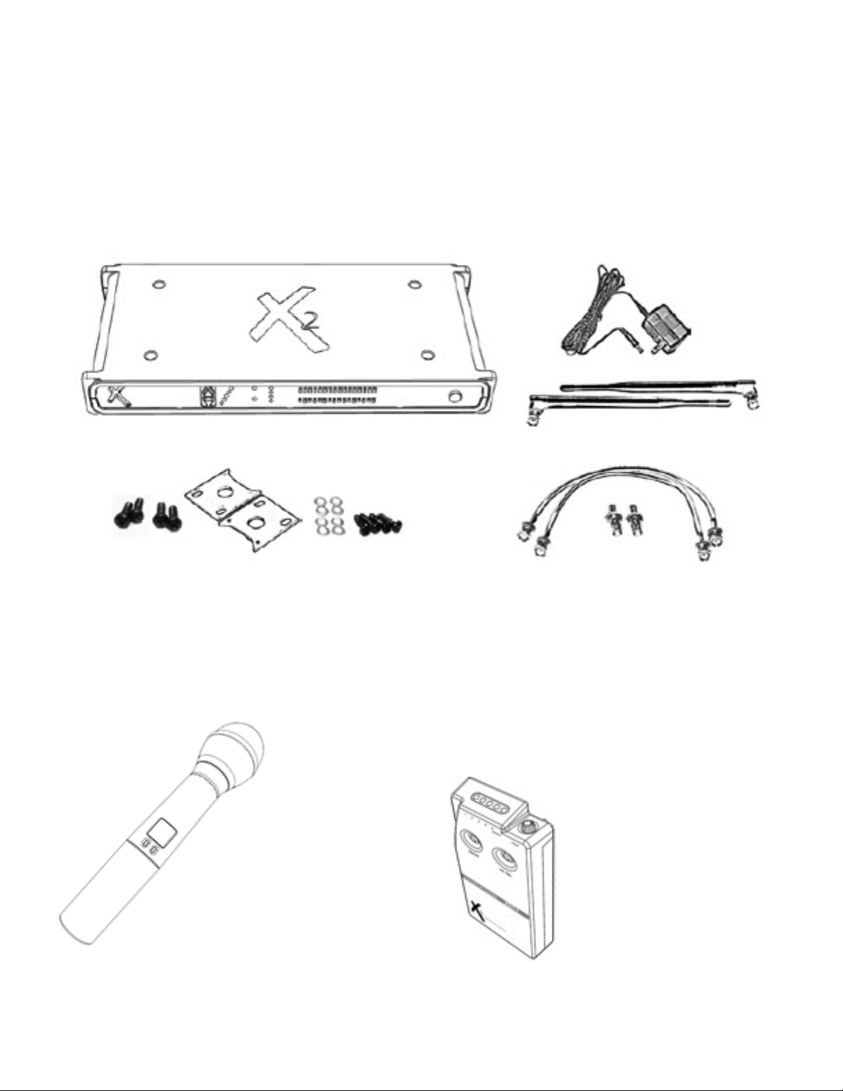
System Components
• (1) XDR4 Digital UHF receiver
• (1) XAC4 (9V DC 500mA power supply for XDR4)
• (2) 1/2 wave antenna
• (1) rackmounting kit (includes rack ears and the necessary mounting hardware (see installation instructions on page 5)
• (1) front-mount antenna kit (includes necessary hardware - see front-mount antenna installation instructions on page 5)
Handheld Systems Include:
(1) XDH4 digital handheld transmitter
•
(1) Microphone capsule
•
(1) Microphone stand clip
•
(2) AA alkaline batteries
•
Bodypack Systems Include:
(1) XDT4 digital bodypack transmitter
•
(1) 9V alkaline Battery
•
1/4” to 1/8” locking connector instrument cable
•
- or lavaliere microphone
- or headset microphone
1
Page 5
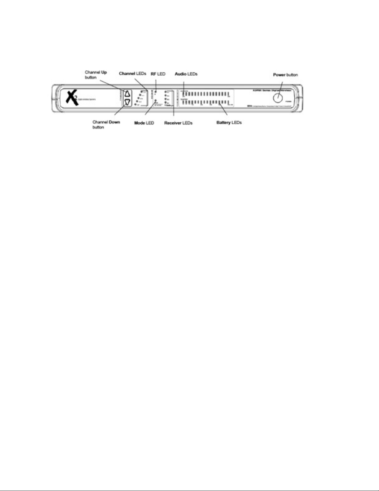
Receiver Controls & Front Panel
FIGURE 1
Power Button
Press once to turn the unit on. To power the unit off, press and hold until the “X2” logo begins to cycle letting you know that the
unit will now turn off.
Channel Up & Down Buttons
Press the UP button to select the next channel. Press the DOWN button to select the previous channel. Button sequence does
not wrap around. For example, once CH5 is selected you must press the DOWN button four times to reach CH1.
Channel LEDs
A blue LED will light indicating the currently selected channel of operation.
RF LED
A red LED will light indicating that an RF signal is present on the currently selected channel.
Mode LED
A green LED will light indicating XDR mode (factory) and ensures that your system is operating at full bandwidth and providing
Q-DiversityPLUS interference protection. A red LED will light indicating that the receiver is currently operating in XDS mode
allowing operation with original XDT1 transmitters from the XDS95 ‘stomp-box’ system. NOTE: While in this mode, the frequency
response will be that of the XDS95 ‘stomp-box’ system (10 Hz - 12 kHz). NOTE: Battery telemetry will be disabled when using
XDT1 transmitters.
Changing Modes
To change the operating mode: power the unit off, press and hold the Channel DOWN button and power up. The unit
will remain in the newly chosen and displayed mode until you repeat this process.
Receiver LEDs
A green LED will light indicating that the unit is receiving data on one of four internal receivers. The unit houses four separate
internal receivers, two of which include internal antenna meaning that the system will operate even without external antenna
attached. NOTE: Range may be adversely affected without attaching the supplied 1/2 wave antenna. RX 1 and 4 represent the
lower frequency while RX 2 and 3 represent the upper frequency. Please see Q-DiversityPLUS description on page 16.
Audio LEDs
Blue LEDs will light indicating the audio signal level. There is no need for a CLIP indicator as the system has greater than 118
dB dynamic range and can accommodate input/output signals up to ~6V peak-to-peak.
Battery LEDs
Green LEDs will light indicating remaining battery life in the transmitter. Each tall bar represents one-hour segments. Each
short bar represents 20 minute segments. The first three LEDs will glow red once the transmitter battery life falls below one
hour. NOTE: Battery telemetry is only available with XDT4 transmitters
2
Page 6
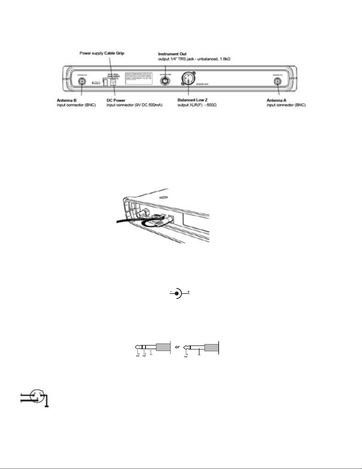
Receiver Connections
FIGURE 2
Antenna A & B Input Connector (BNC)
Diversity antenna inputs A and B. For correct operation connect the supplied detachable antenna by pressing on the BNC connector
and twisting clockwise for ~1/2 turn. NOTE: Antenna inputs ARE NOT DC biased.
Cable Grip
Thread the power supply cable into the CABLE GRIP to secure the connection as shown in figure 3.
FIGURE 3
DC Power Input
DC socket for connection of power supply, 9V DC 500 mA (supplied).
Instrument Output Jack
This 1/4” unbalanced TRS output jack (1.8 kΩ) is voiced at the tip for instrument applications (gentle high-frequency role off at 8 kHz
approximates sound of a 15’ cable), and full bandwidth (10 Hz to 20 kHz) on the ring. Great for ‘tuner’ out or dual amp setups.
Balanced Low Z
Balanced XLR, 600Ω, full-bandwidth output (10 Hz to 20 kHz).
3
Page 7
Antenna Installation
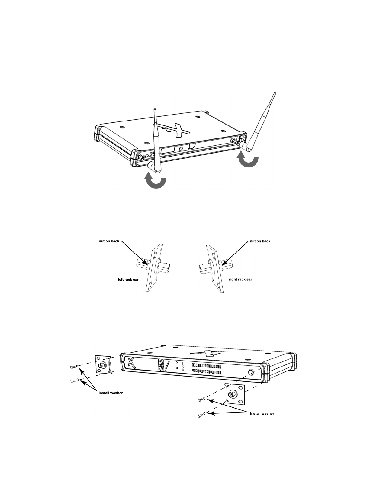
How to Connect the Supplied Antenna
Connect the supplied detachable antennas to the Antenna A and B inputs located on the back panel of the receiver and twist clockwise
for ~1/2 turn as shown in figure 4.
NOTE: Antenna inputs ARE NOT DC biased
FIGURE 4
Preparing Rack Ears for Installation
Connect the supplied BNC connector to each rack ear prior to installing the rack ears to the chassis. Make
certain that the nut goes on the back side of the rack ear as shown in figure 5.
FIGURE 5
Rack Ear Installation
Only mount rack ears onto the chassis with supplied 1/4” hex screw and washers making certain to place a
washer on each side of the rack ear as shown in figure 6.
FIGURE 6
4
Page 8
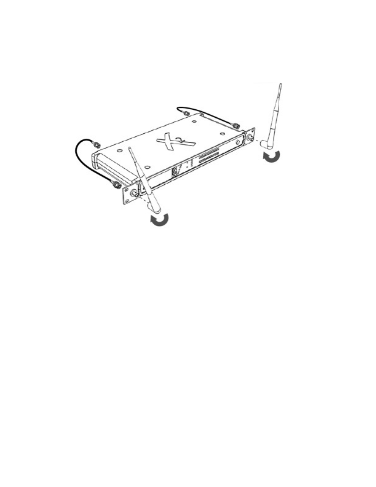
Front-mount Antenna Installation
Connect the supplied BNC patch cables to the Antenna A and B inputs located on the back panel of the receiver and
twist clockwise for ~1/2 turn then connect the other end to the BNC connector located on the back side of each rack ear
and twist cloclwise for ~1/2 turn. Finally, connect the 1/2 wave antenna by pressing on the BNC connector on the front
side of the rack ear and twisting clockwise for ~1/2 turn as shown in figure 7.
NOTE: Antenna inputs ARE NOT DC biased
FIGURE 7
5
Page 9

Handheld Transmitter Controls
FIGURE 8
Power/Set Button
Power Function: Press once to turn the unit on. Press and hold 3 seconds to turn the unit off.
Set Function: This is used for controlling the LCD interface. Use this button to put the transmitter in different modes of operation, accept
selected values or to exit without making any changes.
Select Button
This is used for controlling the LCD interface. Use this button to make parameter selections or increase a value.
LCD Panel
View transmitter performance status and allows the programming of operating channel settings, RF power level settings and lockout
mode.
Main View Locked View
FIGURE 9
6
Page 10

Handheld LCD Interface
Operation - Edit Channel
Press Set once to put the transmitter in Channel Select mode (“ch. 5” will continuously blink). Press Select once to choose this mode
(”Ch.” will stay solid and the “5” will blink). Press Select again to choose the desired channel. Once you’ve made your final selection,
press Set once to put the transmitter on the new channel (”Ch. 5” will blink twice giving you visual confirmation of your selection and will
automatically return to Main View).
Operation - Edit Transmitter Power
Press Set twice to put the transmitter in RF Power edit mode (“TX PWR” and the current value will continuously blink). Press Select
once to choose this mode (”TX PWR” will stay solid and the current value will continuously blink). Press Select again to choose the
desired power setting (HI or LOW). Once you’ve made your final selection, press Set once to put the transmitter on the new power setting (”TX PWR” and the new value will blink twice giving you visual confirmation of your selection and will automatically return to Main
View).
Operation - Set Lock Function
Press Set three times to put the transmitter in Lock edit mode (“ON or OFF” and the lock symbol will continuously blink). Press Select
once to choose this mode (the lock symbol will stay solid and ”ON or OFF” will continuously blink). Press Select again to choose the
desired state. Once you’ve made your final selection, press Set once to put the transmitter in the new state. While in the locked state,
no changes can be made to the transmitter. Additionally, the transmitter cannot be powered down until it is returned back to standard
operation. Should the transmitter be left in this state until the batteries expire, simply replace the batteries and press the power button.
The transmitter will power up and function as previously programmed while remaining in a locked state.
NOTE: Any attempt to make changes to the transmitter will trigger the word “Lock” to blink twice and then display Locked Operation
readout.
NOTE: To regain control of a locked transmitter, press and hold both the Set and Select buttons for three seconds. This calls up the
Lock edit mode.
Operation - Assigning the Transmitter a Name
Press Set four times to put the transmitter in Name edit mode (“Name” will continuously blink). Press Select once to choose this mode
(the first character will blink). Press Select again to choose the desired character. Press Set to move to the next position and continue
this process until you’ve completed entering in the desired name. After making your final character selection in the fourth position,
press Set to complete the naming process. The display will now show its new name in the Main View.
Operation - Selecting Mute Mode
Press Set five times to put the transmitter in Mute edit mode (“MUTE” will continuously blink). Press Select once to choose this mode
(the MUTE symbol will stay solid and ”ON or OFF” will continuously blink). Press Select again to choose the desired state. Once
you’ve made your final selection, press Set once to put the transmitter in the new state. While in Mute mode, the Select button will
promptly cause the audio signal to mute on or off. Should the transmitter be left in this state until the batteries expire, simply replace
the batteries and press the power button. The transmitter will power up and function as previously programmed.
7
Page 11

Preparing the Handheld Transmitter for Use
FIGURE 10
Battery Installation
Remove battery cover by turning counter-clockwise and pulling down. Install the two supplied AA alkaline batteries observing correct
polarity. Then close the battery compartment by turning clockwise until secure.
NOTE: Do not over tighten.
8
Page 12

Bodypack Transmitter Controls
FIGURE 11
Power Button
Press once to turn the unit on. Press and hold to turn the unit off.
Channel Select Button
Press the CH SEL button to select the next channel. Button sequence will wrap around. For example, once CH5 is selected you must
press the CH SEL button one time to reach CH1. Receiver must be set to the same channel as the corresponding transmitter in order to
operate correctly.
LED Display
A blue LED will light indicating the currently selected channel of operation and a red LED indicates remaining battery life in one hour
increments. When idle, these LEDs toggle continuously. During performance, blue LEDs indicate input level. There is no need for a
CLIP indicator as the system has greater than 118 dB dynamic range and can accommodate input signals up to ~6V peak-to-peak.
Operating Modes for the Transmitter
The XDT4 ships in XDS+ mode from the factory and ensures that your system is operating at full bandwidth (10 - 20,000 Hz) while providing frequency diversity interference protection (you can be certain that the transmitter is operating in XDS+ mode if the audio level
LEDs are lighting up in blue when signal is present). If required, the XDT4 can operate in standard XDS mode. This is necessary when
using it with the original XDR1 receiver or other X2 receivers that are operating in standard XDS mode (you can confirm that the transmitter is operating in standard XDS mode if the audio level LEDs are lighting up in red when signal is present).
NOTE: While in standard XDS mode, the frequency response will be 10 - 12,000 Hz and frequency diversity (anti-jam) will be disabled.
NOTE: Battery telemetry will be disabled when using original XDT1 transmitters with XDR2.
9
Page 13

Changing Transmitter Operating Mode
To change the operating mode: power the unit off, press and hold the Channel DOWN button (left button) and power up. The unit will
remain in the newly chosen and displayed mode until you repeat this process.
FIGURE 12
10
Page 14

Transmitter Connectors
FIGURE 13
Threaded Sleeve
Secure the 1/8” TRS unbalanced jack plug in place by screwing down the threaded sleeve onto the input jack socket threads and turn
approximately two times.
Jack Plug
For correct operation, the jack plug must be inserted all the way into the jack socket with the threaded sleeve securely fastened to the
threaded input jack socket.
Threaded Input Jack Socket
Make certain that a secure connection is made for trouble-free operation.
Instrument Input
The instrument input circuit is wired to the ring of the input jack plug and socket.
NOTE: When using anything other than an X2 instrument cable, make certain to ground the tip when using this input (impedance is 1.3
MΩ).
Microphone Input
The microphone input circuit is wired to the tip of the input jack plug and socket.
NOTE: When using any other microphone not supplied by X2, make certain to ground the ring when using this input (impedance is
10KΩ).
NOTE: ~9V DC is supplied at the tip.
11
Page 15

Preparing the Transmitter for Use
Battery Installation
Step 1:
Press and slide the battery door open and connect the 9V battery as shown in figure 14.
FIGURE 14
Step 2:
Insert the battery into the compartment and close the battery door then secure the door by sliding shut as shown in figure 15.
FIGURE 15
Battery Life
Fresh Alkaline batteries should last about ~5.5 hours in the XDT4. NiCad rechargeable batteries will only last about 3.5 hours. Standard
batteries are not recommended. THE BATTERY HOUR DISPLAY WILL ONLY BE ACCURATE FOR ALKALINE BATTERIES. The battery life is calculated inside the each component and displayed in 1 hour increments. Upon power up the battery info will take about one
minute to stabilize, the battery gauge is then accurate within + or - 15 min. You may use batteries
until they are completely drained without affecting the performance of the unit in any way.
12
Page 16

Transmitter Mounting Options
Attaching the Beltpack to Clothing
The bodypack transmitter is attached to clothing (e.g. guitar strap, belt, waistband) with the supplied belt clip as shown in figure 16.
The clip is detachable so that you can also attach the bodypack transmitter with the input jack facing downwards. To do so, remove the
clip and remount it reversing the orientation as shown in figure 17.
For thinner nylon-type guitar straps you can secure the transmitter by weaving the strap through the clip as shown in figure 18 or by
running it straight up and down as in figure 19.
FIGURE 16
FIGURE 18
FIGURE 17
FIGURE 19
13
Page 17

Troubleshooting
Issue
Cause
See Solution...
No sound.
System not turned on. Source malfunction. Improper connection or improper channel selection.
Expired battery.
Power, Signal Source, Cables or RF
Intermittent sound or distorted
sound.
Source malfunction. Improper connection. Multiple
transmitters are set to the same operating channel.
Transmitter has gone out of range. Transmitting
through metal wall. Unknown source of RF in local
area.
Signal Source, Cables or RF
Lack of range.
Improper or lack of antenna connection. Multiple
transmitters are set to the same operating channel.
Unknown source of RF in local area.
RF
Power
Make certain that the transmitter and receiver are receiving sufficient power. The receiver requires 9V DC at 500mA. The handheld
transmitter required 3V DC via two alkaline AA batteries. The bodypack transmitter requires 9V DC via alkaline 9V battery. Check the
battery status indicator on the transmitter and replace if necessary.
Signal Source
Make certain that the source is operating as desired by checking source power, signal levels and connections. If necessary, bypass
digital wireless transmission and check the source directly.
Cables
Make certain that all connections and cables are in working order.
RF
Turn all known transmitters off. Check to see if the red RF LED on the receiver’s front panel is lit. If it is not lit, then the receiver is not
detecting the presence of RF signal on the currently selected channel. If it is lit, then the receiver is detecting the presence of unknown
RF signal. Check to see if any of the green Receiver LEDs are lit. If any are lit, then the receiver is detecting the presence of another X2
transmitter set to the same channel. Locate this unit and either turn it off or switch channels. If none of the green Receiver LEDs are lit,
then the receiver is detecting confirmed RF signal from a source other than an
X2 transmitter. Change the channel and repeat these steps to locate a clear channel.
14
Page 18

Optimizing Performance
RF Interference
An X2 Digital transmission is not susceptible to interference in the traditional ‘analog’ wireless sense. An X2 receiver will only pass digital data that originated from an X2 transmitter set to the same operating channel. If this transmitter has a custom encryption scheme, a
standard X2 receiver will no longer be able to recognize or reproduce the signal. RF interference for X2 systems will only become noticeable when a system’s range has been adversely affected or when the red RF indicator is lit without the desired transmitter in use. In
most cases, the system will still operate reliably with a reduced performance range even when RF interference is present on your channel. Due to the anti-interference/anti-jamming technology available with the XDR-95 system, the chance of having a performance negatively impacted by RF interference is greatly reduced.
Increasing Range
Transmission range depends to a large extent on location and can vary the minimum and maximum performance range. There should
be a “free line of sight” between transmitters and receiving antennas. For best results, maintain a line of sight between transmitter and
receiver antennas. Move receiver antennas away from metal objects or other sources of RF interference (such as CD players, computers, digital effects, network switches, network cables, etc.). We recommend that you employ remote antennas when the receiver position is not the best antenna position for optimum reception. For multiple systems, make certain that each system is operating on it’s own
separate channel.
Multi-channel Operation
For multi-channel operation, it is recommended that you only use channels that are not in use by other performers. Before powering on
additional transmitters, we recommend performing a quick RF scan. This is done at the receiver unit by selecting unused channels and
checking for the presence of RF energy via the RF indicator on the front panel. If the channel is open, power on the desired transmitter
and set it to the open channel. NOTE: When operating more than one system, maintain a minimum distance of 3 ft. from all other receiving antenna that are connected to systems other than your system.
15
Page 19

Warranty Information
X2 Warranty Policy
X2 will repair or replace any defective system within the first two years free of charge. X2 will cover 2-day return shipping costs in the
continental United States. This warranty is transferable, but does not cover abused systems. Terms and conditions subject to change
without notice. Please retain a copy of your dated sales receipt for proof of warranty status should repairs become necessary.
Warning:
Changes or modifications not expressly approved in writing by X2 Corporation may void the users authority to operate this equipment.
This device complies with part 15 of the FCC rules. Operation is subject to the following two conditions: (1) This device may not cause
harmful interference, and (2) this device must accept any interference received, including interference that may cause undesired operation.
RF Exposure Statement
This transmitter must not be co-located or operated in conjunction with any other antenna or transmitter.
NOTE: This equipment has been tested and found to comply with the limits for a Class B digital device, pursuant to part 15 of the FCC
Rules. These limits are designed to provide reasonable protection against harmful interference in a residential installation. This equipment generates, uses and can radiate radio frequency energy and, if not installed and used in accordance with the instructions, may
cause harmful interference to radio communications. However, there is no guarantee that interference will not occur in a particular installation. If this equipment does cause harmful interference to radio or television reception, which can be determined by turning the
equipment off and on, the user is encouraged to try to correct the interference by one or more of the following measures:
-Reorient or relocate the receiving antenna.
-Increase the separation between the equipment and receiver.
-Connect the equipment to an outlet on a circuit different from that to which the receiver is connected.
-Consult the dealer or an experienced radio/ TV technician for help.
This Class B digital apparatus complies with Canadian ICES-003.
Cet appareil numerique de la classe B est conforme a la norme NMB-003 du Canada.
NOTE: This Radio equipment is intended for use in musical professional entertainment and similar applications.
16
Page 20

Service Information
Refer All Servicing to X2
We believe that this equipment is one of the most reliable wireless systems that can be made using current technology, and should provide years of trouble-free use. However, should problems occur, DO NOT attempt to service the unit yourself. Service on this product
should only be performed by X2. THERE ARE NO USER SERVICEABLE PARTS INSIDE.
Obtaining Repair Service
Prior to contacting our service department, please take a moment to check over all of your connections, and make certain that you’ve
read this owners manual. Your X2 dealer may also be able to provide you with additional support. If the problem persists, call X2 at
(916) 779-1040 and request the customer service department. Talk your situation over with one of our technicians; if necessary, you will
be given a return authorization (RA) number and instructions on how to return the unit. All units must be shipped prepaid. COD shipments will not be accepted. For prompt service, indicate the RA number on the
shipping label. Tape a note on top of the unit describing the problem. Include your name and phone number where X2 can contact you
if necessary. Also, please include instructions on where you would like the system to be returned. X2 will pay for 2nd-day shipping back
to you on any repair covered under the terms of this warranty.
Service Address for customers in the USA:
X2 Digital Wireless Systems
4630 Beloit Drive, Suite 20
Sacramento, CA 95838
916-779-1040
17
Page 21

Specifications
Overall System Specifications
Transmission Format:
X2 proprietary digital audio transmission
A/D – D/A Conversion:
24-bit Delta Sigma, 128 times over sampling
Frequency Response:
10 Hz - 20 kHz
Audio Dynamic Range:
>118 dB
Distortion:
0.03% THD
RF Carrier Frequency:
902 MHz to 928 MHz, FSK, dual frequency transmission
Selectable Frequencies:
Five
RF Output Power:
15mw
Audio Output Level:
Unity gain with transmitter input
Polarity:
Positive voltage at input yields positive voltage at output
Transmission Range:
~200 feet line-of-sight (may vary due to local conditions)
FCC Approval:
Part 15 approved, no user-license required
Operating Temp. Range:
–18° to +57° C (0° to +135° F)
XDR2 Receiver Specifications
Output:
2.12V RMS (Unbalanced: 1.8kΩ)
Connectors:
1/4" Unbalanced TRS output 1.8kΩ impedance, tip= instrument voicing,
LED Display:
ring= full bandwidth, sleeve= ground
Controls:
Power On, RF, Channel, Diversity, Battery Life, Audio Level Meter, Power On/Off, Channel
UP and Down
Dimensions (HxWxD):
1.44 x 4.5 x 5.65 in. (3.66 x 11.43 x 14.35 cm)
Power Requirements:
9V DC 300mA via included AC/DC adapter
Weight:
12.8 oz
Housing:
Metal Chassis
XDT4 Transmitter Specifications
Input Impedance:
1.3 MΩ (ring) for Instrument, 10 KΩ (tip) for Mic
Connectors:
1/8" TRS locking connector, ring (+, instrument), sleeve (ground), tip (+, mic)
Controls:
Power On/Off, Channel Select
LED Display:
Five segment - Power On, Channel, Battery Life, Audio Level Meter
Dimensions (HxWxD):
2.4 x 4 x .8" (6.09 x 10.16 x 2.03 cm)
Battery Life:
Switching power supply, ~5.5 Hours (9V alkaline)
Weight:
4 oz (with 9V battery installed)
Housing:
Polycarbonate, impact tested to 300 lbs.
XDH4 Handheld Specifications
Microphone Element:
Dynamic, unidirectional
Controls:
Power On/Off, Channel Select
LED Display:
Five segment - Power On, Channel, Battery Life, Audio Level Meter
Dimensions:
6.25 x 1.5 in.
Power Requirements:
3V DC (~8 hrs. w/ 2x AA alkaline batteries included)
Weight:
6.56 oz (with 2x AA batteries installed)
18
Page 22

Q-DiversityPLUS™ Frequency Diversity Technology
What is it?
A dual-frequency broadcast system that maximizes data isolation from undesired interference. It can also be thought of as two
completely separate ‘true-diversity’ systems operating in tandem. RX 1 and 4 work together to receive the lower frequency while
RX 2 and 3 work together to receive the upper frequency.
What does it do?
Allows XDR95 to provide reliable performance under adverse RF conditions.
Do other types of technology use dual-frequency broadcast?
Multiple frequency broadcasts are not unique. OFDM would be an example of splitting up data over multiple frequencies.
However, X2’s proprietary Q-DiversityPLUS is unique for real-time audio applications.
Why do we need it?
Wireless systems are subject to increased interference due to known and unknown sources of RF interference, including DTV,
cell phones, blackberrys and networking devices. XDR95 was designed to address the needs of professional wireless users
requiring consistent reliable performance even in adverse conditions without any loss to sound quality.
How does it work?
In the transmitter, a proprietary digital data stream that includes a digital representation of the audio signal is split and modulated
on two separate RF carrier frequencies. The receiver contains a quadraplex of separate receiver sections that work simultaneously
to receive the two RF signals. Two receiver sections are directly connected to two internal antennae, while two others are
fed RF signals via two chassis mounted BNC connectors. These sections work simultaneously to receive the two RF signals
that contain the transmitted digital data.
Why is it better?
Q-DiversityPLUS allows the XDR95 to exceed other wireless systems in terms of freedom from negative audio side-effects of
increased interference and longevity of performance in the field.
FIGURE 20
19
Page 23

Additional Information
Architect’s and Engineer’s Specifications
The wireless system shall utilize digital conversion and operate in the UHF band between 902 MHz and 928 MHz for operation in North
and South America. The system shall transmit a digital representation of the audio signal over two separate RF frequencies that include a unique digital code sequence that identifies the transmission to the receiver thus locking out all other sources of interference
without the need of squelch circuitry. The system shall include the option of changing the compatible preset operating frequencies enabling up to 5 systems to operate simultaneously in the same location without interfering with one another.
Bodypack transmitters shall be powered by a single 9 volt battery and shall have a power on/off button, a channel select button, and an
LED display automatically indicating power status, battery strength, operating channel and audio level. Handheld transmitters shall be
powered by two AA batteries and shall have a power/set button, a select button, as well as a user programmable menu-driven backlit
LCD showing channel, audio level, RF power mode, control lock status, name, and battery strength. Available transmitters shall include: a body pack for use with electric guitars, basses and other electric instruments, and lavaliere and headset microphones for vocals, and a handheld microphone for vocals. Transmitters shall have a DC/DC converter to ensure consistent performance, even if
battery voltages change.
The receiver shall have two channel select buttons, one for ‘next’ channel and one for ‘previous’ channel. The receiver LED display
shall indicate the current operating channel, RF present, Diversity status, Audio Level, remaining Battery Level in the transmitter with a
resolution to within 20 minute increments being preferred. The system shall use dual frequency transmission technology such as QdiversityPLUS to maximize RF performance and to eliminate interference, audio artifacts and unwanted noise. The receiver shall include four Receiver LEDs (one for each internal receiver), automatically indicating the operating status of each internal receiver. The
system shall be capable of handling an input and output signal of up to 6 volts peak-to-peak without the use of compander ICs.
The system shall be the X2 XDR-95 Digital Wireless System.
20
Page 24

Friday, January 25, 2008
X2 Digital Wireless Systems
4630 Beloit Drive, Suite 20
Sacramento CA 95838 U.S.A.
Phone: (916) 779-1040
Fax: (916) 779-1041
Web Site
www.x2digitalwireless.com
 Loading...