

Page 1

Service Training
Linde IC-Engined Fork Truck
H 50/60/70/80 D/T
H 50/60/70/80 D-02/T-02
H 50/60/70/80 D-03/T-03
Type 353
This training material is only provided for your use and remains the exclusive property of
LINDE MATERIAL HANDLING
Page 2

Page 3

Service Training
09.06
TABLE OF CONTENT
4 IC-engined fork truck H 50/60/70/80, Type 353 1
4.1 Engine drive 1
4.1.1 Engine model BF6M 1012 E 1
4.1.1.1 Engine specifications 1
4.1.1.1.1 Explanation of the engine number 2
4.1.1.2 Changing and tightening the drivebelt 3
4.1.1.3 Adjusting valve clearance 4
4.1.1.4 Adjusting the injection valve 7
4.1.1.5 Checking the compression pressure 9
4.1.1.6 Cylinder head 10
4.1.1.7 Adjusting the begin of delivery 12
4.1.8 Special tools 16
4.1.2 Engine model BF6M 2012 18
4.1.2.1 Overview of engine components 18
4.1.2.2 Engine specifications 20
4.1.2.2.1 Explanation of the engine number 11
4.1.2.3 Replacement of V-ripped belt 22
4.1.2.4 Adjusting valve clearance 23
4.1.2.5 Checking and adjusting leak-fuel-free injection nozzles 24
4.1.2.6 Thermostat 30
4.1.2.7 Checking the compression pressure 32
4.1.2.8 Cylinder head 33
4.1.2.9 Injection pump 35
4.1.2.9.1 Adjusting the begin of delivery 35
4.1.2.9.2 Replacement of the injection pump 37
4.1.2.10 Heater flange 43
4.1.2.11 Special tools 46
4.2 Transmission 1
4.2.1 Hydrostatic transmission 2
4.2.1.1 Schematic diagram of the drive 3
4.2.1.2 Transmission specifications 4
4.2.1.3 Hydraulic circuit diagram 6
4.2.2 Operation of the hydrostatic transmission 20
4.2.2.1 Travel control unit P 20
Page 4

09.04
Service Training
4.2.2.2 Operation of control valve block N = Power Limiter 23
4.2.2.3 Braking 24
4.2.2.4 Auxiliary brake 24
4.2.2.5 Lock-out logic - reversing lock 26
4.2.2.6 Flushing of the circuit and housing 28
4.2.3 Hydraulic remote control 30
4.2.3.1 Adjustments 31
4.2.3.1.1 Hydraulic neutral position 31
4.2.3.1.2 Primary adjustment of start of control 31
4.2.3.1.3 Mechanical limitation of the swashplate angle 31
4.2.3.1.4 Hydraulic remote control HPV 105 -02 32
4.2.3.1.5 Reversal lock (logic lock out) 34
4.2.3.1.6 Reducing the truck speed 34
4.2.4 Wheel drive 35
4.2.4.1 Reduction gearbox with disc brake (GR 80 -02/-03/-04) 36
4.2.4.2 Servicing the reduction gearbox (GR 80 -02/-03/-04) 38
4.2.4.3 Disc brake repairs 39
4.2.4.4 Reduction gearbox GR 80 -06 with multiple disc brake 40
4.2.4.5 Repair on the reducing gear GR 80 -06 41
4.2.5 Troubleshooting 48
4.2.5.1 Connecting diagram for troubleshooting 48
4.2.5.2 Tools and aids for measurements 50
4.2.5.3 Explanations to troubleshooting 52
4.2.5.4 Hydraulic speed control for the engine 53
4.2.5.4.1 Functional test 53
4.2.5.4.2 Troubleshooting 53
4.2.5.5 Hydraulic braking system 58
4.2.5.5.1 Functional test 58
4.2.5.5.2 Troubleshooting 58
4.2.5.6 Pressure equality and start of control 61
4.2.5.6.1 Functional test 61
4.2.5.6.2 Troubleshooting 61
4.2.5.7 Hydrostatic travel drive 65
4.2.6 Test and adjustment instructions for hydraulic primary and secondary control 77
4.2.6.1 Q
4.2.6.2 Q
4.2.6.3 Q
of variable displacement pump BPV 100 78
max
of hydraulic motors HMV 105 80
max
of hydraulic motors HMV 105 81
min
Page 5

Service Training
4.3 Chassis 1
4.3.1 Overhead guard - torsion mounting 2
4.3.1.1 Work on the overhead guard 3
4.4 Steering system 1
4.4.1 Power steering circuit diagram 2
4.4.2 Series 304 steering axle 4
4.4.2.1 Description 4
4.4.3 Steering axle removal 5
4.4.3.1 Steering axle installation 6
4.4.4 Steering axle repairs 6
4.4.4.1 Renewing the wheel bearings 7
4.4.4.2 Steering knuckle removal and installation 8
4.4.4.3 Steering cylinder removal and installation 10
4.4.4.4 Replacing the steering cylinder seals 12
4.4.4.5 Steering stop adjustment 13
09.04
4.5 Controls 1
4.5.1 Accelerator and brake pedal adjustment 2
4.5.2 Speed control 5
4.5.2.1 Speed control up to 10/95 5
4.5.2.2 Speed control from 11/95 7
4.5.3 Medium wheel speed 8
4.5.4 Start of drive wheel rotation 9
4.5.5 Brake shaft stop screws 10
4.5.6 Symmetry of the travel control 11
4.5.6.1 Drive wheel start of rotation 11
4.5.6.2 Engine speed increase 12
4.5.7 Pressure difference Δp13
4.5.8 Modification of engine acceleration 14
4.6 Electrical system 1
4.6.1 Wiring diagram 2
4.6.2 Wiring diagram for options 6
4.6.3 Wiring diagram, 353 -02 9
4.6.4 Wiring diagram for options, 353 -02 13
4.6.5 Wiring diagram, 353 -03 Diesel 17
4.6.6 Wiring diagram for options, 353 -03 21
Page 6

12.05
4.6.7 Electrical system circuit diagram, type 353 -03 LPG 25
4.6.8 Wiring diagram for options, 353 -03 29
4.6.9 Central electrical system 34
4.6.10 Central electrics of series 353 -03 36
4.6.10.1 Relay and fuses of 353 -03 Diesel 36
4.6.10.2 Relay and fuses of 353 -03 LPG 38
4.6.10.3 Relay and fuses for 353 -03 particulate trap 40
4.7 Working hydraulics 1
4.7.1 Working hydraulics circuit diagram 2
4.7.1.1 Explanation of the working hydraulics 3
4.7.2 Tilt cylinder 4
4.7.2.1 Tilt cylinder removal, installation, adjustment, sealing 5
4.8 Mast 1
4.8.1 Mast removal 2
4.8.2 Lift cylinder removal, installation 3
4.8.3 Sealing the lift cylinder 4
Service Training
4.9 LP gas model H 50/60/70/0, Type 353 1
4.9.1 Drive engine 1
4.9.1.1 Technical data on engine 1
4.9.1.1.1 Technical data on engine up to 12/2004 1
4.9.1.1.2 Technical data on engine from 01/2005 2
4.9.1.2 Note on the engine number 3
4.9.1.3 Changing and tensing V-belt 4
4.9.1.4 Checking and setting valve clearance 5
4.9.1.5 Removing and installing the cylinder head 6
4.9.2 Electrical system 9
4.9.2.1 Electronic ignition system 9
4.9.2.1.1 Electronic ignition system up to 12/2004 9
4.9.2.1.2 Electronic ignition system from 01/2005 14
4.9.2.1.2.1 Mechanical ignition timing 19
4.9.2.2 Electronic engine-speed control 23
4.9.2.3 Electrical system circuit diagram 26
4.9.2.3.1 Electrical system circuit diagram up to 12/2004 26
4.9.2.3.2 Electrical system circuit diagram from 01/2005 30
Page 7

Service Training
4.9.3 Propellant gas system 33
4.9.3.1 Diagram 33
4.9.3.2 Functional description of the propellant gas system 34
4.9.4 Inspections and adjustments 42
4.9.4.1 Ignition system 42
4.9.4.2 Installation of the engine speed control system 46
4.9.4.3 Inspection of the engine speed control system 48
4.9.4.4 Adjustment of the propellant gas mixers 53
12.05
Page 8

12.05
Service Training
Page 9

Service Training
09.04
4 IC-ENGINED FORK TRUCK H 50/60/70/80, TYPE 353
4.1 ENGINE DRIVE
4.1.1 ENGINE MODEL BF6M 1012 E
4.1.1.1 ENGINE SPECIFICATIONS
Engine model BF6M 1012 E
Displacement 4790 cc
Power 85 kW at 2250 rpm
Opening pressure of injection valve 260 bar
Compression ratio 17,5 : 1
Compression 28 - 33 bar
Maximum difference in pressure 4 bar
Firing order 1 - 5 - 3 - 6 - 2 - 4
+ 0,1
+ 0,1
mm
mm
Valve clearence (cold) inlet: 0,3
outlet: 0,5
+ 50
Lower idling speed 750
Upper idling speed 2300
rpm
+ 50
rpm
Oil pressure at lower idling speed
and 125 °C oil temperature min. 0,8 bar
Section 4.1
Page 1
Count the cylinders beginning at the flywheel end.
Page 10

Section 4.1
Page 2
4.1.1.1.1 EXPLANATION OF THE ENGINE NUMBER
09.04
Service Training
1 Manufacturer's plate with type and engine number
2 Engine number stamped on the crankcase
NOTE: A second type plate was affixed to the rocker cover by Linde.
EXPLANATION OF THE ENGINE NUMBER
B F 6 M 1012 E
external cooling
series
coolant/water
number of cylinders
aspirated engine
turbocharged
Page 11

Section 4.1
Service Training
4.1.1.2 CHANGING AND TIGHTENING THE DRIVEBELT
CHANGING THE DRIVEBELT
- Slacken the alternator and tensioner fastening screws (2).
- Turn the tensioning screw (3) anti-clockwise, press the alternator in and remove the drivebelt.
- Check the pulley for wear, renewing it if necessary.
- Install a new drivebelt.
TIGHTENING THE DRIVEBELT
- Turn the tensioning screw (3) clockwise until the required tension is obtained.
- Check the tension with a gauge (1), Part No. 000 941 9435.
- Tighten the screws (2) again.
Settings:
Initial installation 400
Check after 15 minutes Operation under load
and retighten the belt, if necessary 300 ± 50 N
With re-use 250 ± 50 N
+ 50
09.04
N
Page 3
Page 12

Section 4.1
Page 4
4.1.1.3 ADJUSTING VALVE CLEARANCE
The adjustment can be carried out when the engine is cool or warm after a cooling period of at least 30
minutes (oil temperature < 80 °C).
Valve clearance: Inlet 0.3 mm
Outlet 0.5 mm
VALVE CLEARANCE SCHEMATIC
09.04
Service Training
Crankshaft position 1
Turn the engine until the valve inlet and outlet of
cylinder 1 are just open.
adjustable
NOTE: When a new rocker cover is installed, increase the valve clearance by 0.1 mm. Adjust the valve
clearance to normal values after 50 service hours.
Crankshaft position 2
Turn the engine one full revolution (360 °).
not adjustable
Page 13

Section 4.1
Service Training
VALVE CLEARANCE ADJUSTMENT BY MEANS OF A TORQUE ANGLE GAUGE FROM SERIAL
NUMBER E1 X353 T 000268
In engines which are equipped with a thrust washer in the valve spring retainer (Fig. A1), the valve
clearance can only be adjusted by means of a torque angle gauge.
This method using a torque angle gauge may also be applied for the DEUTZ engines BF6M 1012 / 2012
installed in series 353 trucks up to now, which have so far been adjusted by means of the feeler gauge
method.
09.06
Page 5
Fig. A1 Valve gear with pressure disk
New method for checking and adjusting the valve clearance (with torque angle gauge)
Prerequisite: The engine must have cooled down for at least 30 minutes; oil temperature below 80 °C.
- Carry out the preparations (e.g. remove cylinder head cover).
- Turn crankshaft until valve overlap on cylinder no. 1 is reached. This means: Inlet valve starts opening,
outlet valve closes.
- Crankshaft position 1 in accordance with corresponding adjustment diagram (see "valve clearance
schematic").
- Fix magnet of torque angle gauge on cylinder head.
- Place torque anlge gauge 8190 with screw driver bit on setting screw. Use screw driver bit 8191.
Checking the valve clearance
- Put T-handle (4) on torque angle gauge (1) (Fig. 5).
- Loosen locknut (3) on rocker arm and support
setting screw (2) with T-handle against turning
(figure A5).
- Set torque angle gauge to 0 (zero) and suppport
setting screw (2) with T- handle against turning
(figure A4).
- Turn setting screw with screw driver bit clockwise
until rocker arm contacts thurst washer free from
clearance.
- Read the value (setting angle) on the torque angle
gauge.
Fig. A5
Page 14

Section 4.1
Page 6
Adjustment of valve clearance
- Set torque angle gauge to 0 (zero) (Fig. A4).
Take care not to turn the setting screw!
- Turn setting screw back (counterclockwise) until reaching the corresponding
setting angle.
Setting angle of inlet valve: 75°
outlet valve: 120°
Locknut tightening torque: 20 Nm
- Put T-handle on torque angle gauge (Fig.
A5).
- Support setting screw with T-handle and
tighten locknut with socket wrench (open
end). Observe instructions for tightening!
- Adjust valve clearance for the remaining
valves as described above.
- Remove tools.
09.06
Service Training
Fig. A 4 Valve clearance adjustment
(example: TCD 2012 2V with exhaust gas
recirculation)
1 = Torque angle gauge 8190
Tools required for adjustment
Deutz part number 8190 8191
The required special tools may be ordered from the address below.
Please quote the corresponding ordering number.
WILBÄR
Wilhelm Bäcker GmbH & Co. KG
Postfach 140580
D42826 Remscheid
E-Mail: info@wilbaer.de
Tel.: ++49 (0) 2191 9339-0
Page 15

Section 4.1
Service Training
4.1.1.4 ADJUSTING THE INJECTION VALVE
CHECKING THE OPENING PRESSURE
NOTE: Use only test oil acc. to ISO 4113 or diesel fuel for the test.
CAUTION: When checking injection nozzles, take care that the fuel jet does not hit the hands. Due to the
high pressure, the fuel can penetrate the skin and cause severe injuries.
- Install the injection nozzle on the nozzle tester.
- Press the lever down slowly. Read the pressure at the start of fuel ejection and adjust the pressure, if
necessary, by changing the shims.
09.06
Page 7
Specified pressure
New injection nozzles 260
Pressure for re-usability 255
ADJUSTING THE INJECTION NOZZLE OPENING PRESSURE
- Clamp the holder 110110 for the injection valve in a vise.
- Place the top part of the injection holder into the holder 110110 and unscrew the union nut.
Sequence of disassembly:
1. Union nut
2. Injection nozzle
3. Intermediate piece
4. Pressure spindle
5. Compression spring
6. Shims
7. Nozzle body
+8
bar
+8
bar
- Adjust the pressure by fitting the correct shim. The thicker the shim,
the higher the opening pressure will be. Re-assemble the injection
valve. Tighten the union nut to a torque of 40 - 50 Nm. Check the
injection valve with the nozzle tester.
Page 16

Section 4.1
Page 8
CHECKING FOR LEAKS
- Dry the nozzle and nozzle holder - blow dry with an air jet.
- Slowly press the tester hand lever down until a pressure approx. 20 bar under the previously obtained
opening pressure is reached.
- The nozzle does not leak if no drops of fuel show within 10 seconds.
If a drop of fuel leaks out, disassemble the injection valve and eliminate the leak by cleaning the injection
nozzle. If this does not remedy the leak, renew the injection valve.
Do not rework the valve.
BUZZING AND JET TEST
- Shut off the compression tester pressure gauge.
The buzzing test is an audible test for determining if the needle is moving easily in the nozzle body. New
injection nozzles have a different buzzing behaviour as opposed to used ones. Wear in the area of the
needle seat lets the buzzing behaviour deteriorate. A nozzle that does not buzz despite cleaning must be
replaced.
09.06
Service Training
A used injection valve must buzz audibly if the hand lever is operated quickly and it must produce a finely
atomized spray. The shape of the spray can vary greatly from that of a new injection valve.
INSTALLING THE INJECTION NOZZLE
- Using some grease, slide the seal onto the injection valve.
- Insert the injection valve.
- Put the clamping shoe in place.
- Torque the screws to 16
+ 5
N.
Page 17

Section 4.1
Service Training
4.1.1.5 CHECKING THE COMPRESSION PRESSURE
- Remove the injection nozzle.
- Check the valve clearance.
- Insert and fasten connector 100110 along with the special seal.
- Connect a compressometer and crank the engine with the starter.
Specified pressure 28 - 33 bar
Max. difference in pressure 4 bar
NOTE: The measured compression pressure depends on the RPM of the starter when the
measurement is carried out and on the altitude of the place the engine is operated in.
For this reason it is not possible to define exact limits. The compression pressure check is
only recommended as a means of comparing all cylinders in relation to each other. If the
difference in pressure exceeds 15 %, dismantle the appropriate cylinder unit and determine
the cause.
09.06
Page 9
Page 18

Section 4.1
Page 10
4.1.1.6 CYLINDER HEAD
REMOVING THE CYLINDER HEAD
- With the engine cool, slacken the cylinder head bolts evenly and in steps in the reverse order as given
in the schematic "Cylinder head bolt tightening sequence".
DETERMINING THE CYLINDER HEAD GASKET
NOTE: For the adjustment of the gap, there are 3 different cylinder head gaskets, which identifiable
by holes.
- Place the dial gauge along with spacers 10075C on the sealing surface of the cylinder block and set the
dial gauge to "0".
- Turn the piston to TDC and note the projecting length of the piston at the points of measurement.
- Select the correct cylinder head gasket according to the largest projecting length of the piston.
Projecting length Identification of
of piston cylinder head gasket
09.06
Service Training
0.43 - < 0.64 mm 1 hole
0.64 - < 0.74 mm 2 holes
0.74 - 0.85 mm 3 holes
Page 19

Section 4.1
Service Training
INSTALLING THE CYLINDER HEAD
NOTE: Sealing surfaces for cylinder head gaskets must be clean and free of oil. Pay attention to the
fitting sleeve.
- Check the cylinder head for warping.
- Put the cylinder head in place.
- Check the cylinder head bolts for stretching, see "Visual check".
- Lightly the oil and screw in the cylinder head bolts.
NOTE: Use the cylinder head bolts no more than 5 times.
- Insert the push rods.
- Mount the rocker arm bracket.
- Slightly oil and screw in the long cylinder head bolts.
- Torque the cylinder head bolts as specified and according to the tightening sequence.
Pre-tightening: 1st step 30 Nm
2nd step 80 Nm
Retightening: 90°
09.06
Page 11
CYLINDER HEAD BOLT TIGHTENING SEQUENCE
Manifold Side
Page 20

Section 4.1
Page 12
4.1.1.7 ADJUSTING THE BEGIN OF DELIVERY
If an injection pump must be replaced, the begin of delivery must be re-adjusted by determining the shim
thickness anew.
DETERMINING THE SHIM THICKNESS
The old injection pump and shim are not required for this procedure.
NOTE: From 4/95, the mounting depth of the injection pump has been increased by 10 mm so that the
EP code changes from 70 to 170 and the basic dimension L
mm to 119 mm.
The metod of determining the thickness of the shims for the old versions remains the same.
Proceed as follows:
In the column marked "EP", read the EP code for cylinder 3 on the type plate on the rocker cover,
e.g. 070 or 170 (reading sequence: line 1 = cylinder 1, line 2 = cylinder 2, etc.).
09.06
Service Training
of the injection pump from 109
0
Page 21

Section 4.1
Service Training
09.96
09.06
Page 13
Take the corrected injection pump installation dimension (EK) in Table 1a/1b according to the EP code,
e.g. 111.725 mm.
Table 1a: EP code beginning with '0'
E
K
(mm) (mm) (mm) (mm) (mm)
110.0 110.6 111.2 049 111.8 073 112.4 097
110.025 110.625 111.225 050 111.825 074 112.425 098
110.05 110.65 111.25 051 111.85 075 112.45 099
110.075 110.675 111.275 052 111.875 076 112.475 100
110.1 110.7 111.3 053 111.9 077 112.5 101
110.125 110.725 111.325 054 111.925 078 112.525 102
110.15 110.75 031 111.35 055 111.95 079 112.55 103
110.175 110.775 032 111.375 056 111.975 080 112.575 104
110.2 110.8 033 111.4 057 112.0 081 112.6 105
110.225 110.825 034 111.425 058 112.025 082 112.625 106
110.25 110.85 035 111.45 059 112.05 083 112.65
110.275 110.875 036 111.475 060 112.075 084 112.675
110.3 110.9 037 111.5 061 112.1 085 112.7
110.325 110.925 038 111.525 062 112.125 086 112.725
110.35 110.95 039 111.55 063 112.15 087 112.75
110.375 110.975 040 111.575 064 112.175 088 112.775
110.4 111.0 041 111.6 065 112.2 089 112.8
110.425 111.025 042 111.625 066 112.225 090 112.825
110.45 111.05 043 111.65 067 112.25 091 112.85
110.475 111.075 044 111.675 068 112.275 092 112.875
110.5 111.1 045 111.7 069 112.3 093 112.9
110.525 111.125 046 111.725 070 112.325 094 112.925
110.55 111.15 047 111.75 071 112.35 095 112.95
110.575 111.175 048 111.775 072 112.375 096 112.975
Code E
K
Code E
K
Code E
K
Code E
K
Table 1b: EP code beginning with '1'
Code
E
K
(mm) (mm) (mm) (mm) (mm)
120.0 120.6 121.2 149 121.8 173 122.4 197
120.025 120.625 121.225 150 121.825 174 122.425 198
120.05 120.65 121.25 151 121.85 175 122.45 199
120.075 120.675 121.275 152 121.875 176 122.475 200
120.1 120.7 121.3 153 121.9 177 122.5 201
120.125 120.725 121.325 154 121.925 178 122.525 202
120.15 120.75 131 121.35 155 121.95 179 122.55 203
120.175 120.775 132 121.375 156 121.975 180 122.575 204
120.2 120.8 133 121.4 157 122.0 181 122.6 205
120.225 120.825 134 121.425 158 122.025 182 122.625 206
120.25 120.85 135 121.45 159 122.05 183 122.65
120.275 120.875 136 121.475 160 122.075 184 122.675
120.3 120.9 137 121.5 161 122.1 185 122.7
120.325 120.925 138 121.525 162 122.125 186 122.725
120.35 120.95 139 121.55 163 122.15 187 122.75
120.375 120.975 140 121.575 164 122.175 188 122.775
120.4 121.0 141 121.6 165 122.2 189 122.8
120.425 121.025 142 121.625 166 122.225 190 122.825
120.45 121.05 143 121.65 167 122.25 191 122.85
120.475 121.075 144 121.675 168 122.275 192 122.875
120.5 121.1 145 121.7 169 122.3 193 122.9
120.525 121.125 146 121.725 170 122.325 194 122.925
120.55 121.15 147 121.75 171 122.35 195 122.95
120.575 121.175 148 121.775 172 122.375 196 122.975
Code E
K
Code E
K
Code E
K
Code E
K
Code
Page 22

Section 4.1
Page 14
09.96
09.06
Service Training
Read the code for the injection pump length (A) on the new injection pump, e.g. 53.
The basic dimension of the injection pump (L
) is 109/119 mm.
0
Determine the theoretical thickness of the shim (T
T
= EK - (L0 + A/100)
S
).
S
TS = 111.725 mm - (109 mm + 53/100 mm) or TS = 121.725 mm - (119 mm + 53/100 mm)
T
= 2.195 mm
S
Choose the thickness of the shim (SS) according to Table 2.
T
2.195 = SS 2.2 mm
S
Table 2
Theor. Thickness Shim Theor. Thickness Shim
" Thickness "Ts" Thickness
"T
S
(mm) (mm) (mm) (mm)
0.95 - 1.049 1.0 2.45 - 2.549 2.5
1.05 - 1.149 1.1 2.55 - 2.649 2.6
1.15 - 1.249 1.2 2.65 - 2.749 2.7
1.25 - 1.349 1.3 2.75 - 2.849 2.8
1.35 - 1.449 1.4 2.85 - 2.949 2.9
1.45 - 1.549 1.5 2.95 - 3.049 3.0
1.55 - 1.649 1.6 3.05 - 3.149 3.1
1.65 - 1.749 1.7 3.15 - 3.249 3.2
1.75 - 1.849 1.8 3.25 - 3.349 3.3
1.85 - 1.949 1.9 3.35 - 3.449 3.4
1.95 - 2.049 2.0 3.45 - 3.549 3.5
2.05 - 2.149 2.1 3.55 - 3.649 3.6
2.15 - 2.249 2.2 3.65 - 3.749 3.7
2.25 - 2.349 2.3 3.75 - 3.850 3.8
2.35 - 2.449 2.4
""S
"S
S
S
"
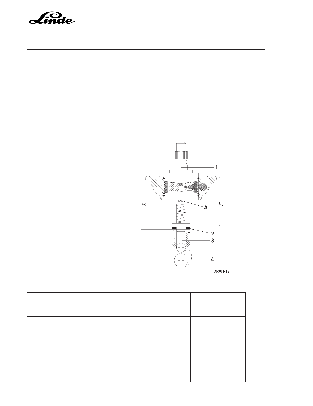
1 Injection pump
2 Shim thickness S
S
3 Roller shaft
4 Camshaft on base circle
A Code
E
Installation dimension
K
L0Basic dimension 109/119 mm
Page 23

Section 4.1
Service Training
INSTALLING THE INJECTION PUMP
- Place the required shim (2) on the roller shaft.
- Turn the injection pump control lever to the stop position.
- Set the roller shaft (3) on the base circle.
- Slightly oil the O-ring and the hole for the ring.
- Remove the shut-off solenoid and replace by device 100830.
Bring the control rod to the stop position with device 100800 and lock it in this position.
- Insert the injection pump (1).
- Install the flange and tighten the bolts evenly to a torque of 5 Nm.
- Loosen the bolts by 60 °.
- Using socket head 110460 and the torque spanner, turn the injection pump several times clockwise and
anti-clockwise by 5 ° to 15 ° and determine the average friction torque (RM), e.g. 4.8 Nm.
- Turn the injection pump anti-clockwise as far as the stop with an average friction torque (RM) of 4.8 Nm
+ 1 Nm = 5.8 Nm and hold it in place.
Tighten the flange bolts alternately to a torque of 7 Nm, 10 Nm and 30 Nm.
- Remove device 100830 and, using a screwdriver, check the control rod for ease of movement by sliding
it back and forth.
- Reconnect the plug on the shut-off solenoid and switch on the ignition.
- Install the shut-off solenoid with a new seal.
09.96
09.06
Page 15
NOTE: Oil the seal lightly.
Tighten the screws to a torque of 21 Nm.
NOTE: The shut-off solenoid must click when the ignition is switched on and off.
Page 24

Section 4.1
Page 16
4.1.8 SPECIAL TOOLS
E 14 Torx socket heads, long version
E 20
51 Socket head, 15 mm, long version for injection valve
(union nut)
2461 Compression pressure tester
09.06
Service Training
7532 Torque spanner
7773 A Socket spanner 1/4 "
8189 Torx tool kit
91 107 V-belt tension gauge
100 110 Connector for compression pressure tester
Page 25

Service Training
100 400 Dial gauge M2T with locking ring
100 750 Dial gauge with spacers for measuring TDC and projecting
length of piston
110 110 Holder for injection valve, 11 mm
110 460 Socket head for turning the injection pump
09.96
09.06
Section 4.1
Page 17
114 010 Tool for connecting glow plug cables
142 710 Removal tool (hook) for crankshaft sealing rings
142 890 Assembly tool for rear crankshaft sealing ring
142 900 Assembly tool for crankshaft sealing ring
Clamping device for control rod
Address your order for special tools to:
Fa. Wilbär, P.O. Box 14 05 80, D-42826 Remscheid
Page 26

Section 4.1
Page 18
4.1.2 ENGINE MODEL BF6M 2012
4.1.2.1 OVERVIEW OF ENGINE COMPONENTS
09.06
Service Training
Page 27

Service Training
1 Generator
2 Oil filler hole
3 Heater flange
4 Coolant connection-recovery line
5 Fan pulley
6 Fuel lift pump
7 Coolant pump
8 V-belt pulley on crankshaft
9 Belt tensioner pulley
10 Mounting legs
11 Oil pan
12 Oil filling nozzle
13 Öil filter casing with engine oil cooler
14 Oil level dipstick
15 Provisions for attaching a compressor or hydraulic pump
16 Fuel filter cartridge
17 Öil filter cartridge
18 Lifting magnet
09.06
Section 4.1
Page 19
Page 28

Section 4.1
Page 20
09.06
Service Training
4.1.2.2 ENGINE SPECIFICATIONS
Engine model BF6M 2012 E
Displacement 6060 cc
Power 74.9 kW at 2200 rpm
Opening pressure of injection valve 260 bar
Compression ratio 19 : 1
Compression 30 - 38 bar
Maximum difference in pressure 4 bar
Firing order 1 - 5 - 3 - 6 - 2 - 4
+ 0,1
+ 0,1
mm
mm
Valve clearence (cold) inlet: 0,3
outlet: 0,5
Lower idling speed 800 rpm
+ 50
Upper idling speed 2300
rpm
Oil pressure at lower idling speed
and 125 °C oil temperature min. 0,8 bar
Count the cylinders beginning at the flywheel end.
Page 29

Service Training
4.1.2.2.1 EXPLANATION OF THE ENGINE NUMBER
09.06
Section 4.1
Page 21
1 Manufacturer's plate with type and engine number
2 Engine number stamped on the crankcase
NOTE: A second type plate was affixed to the cylinder head cover by Linde.
EXPLANATION OF THE ENGINE NUMBER
B F 6 M 2012 E
external cooling
series
coolant/water
number of cylinders
aspirated engine
turbocharged
Page 30

Section 4.1
Page 22
4.1.2.3 REPLACEMENT OF V-RIPPED BELT
Fit the V-ripped belt and tension it.
Pressh the belt tensioner pulley (1) in direction of the
arrow. Fit the V-ripped belt, and finally place it on pulley
(2). Loosen the belt tensioner pulley in opposite direction
to the arrow until the V-ripped belt is tensioned.
If the V-ripped belt is used again, make sure to observe
the wear limit.
Measure the distance "a" between the lug of the movable
tensioning arm and the stop of the fixed tensioner housing.
If the distance "a" is less than 3 mm, the V-ripped belt must
be replaced.
09.06
Service Training
The V-ripped belt is equipped with a spring-loaded belt
tensioner pulley that tensions automatically, and it is not
re-tightened.
Page 31

Section 4.1
Service Training
4.1.2.4 ADJUSTING VALVE CLEARANCE
The adjustment can be carried out when the engine is cool or warm after a cooling period of at least 30
minutes (oil temperature < 80 °C).
09.06
Page 23
Valve clearance: Inlet 0.3
Outlet 0.5
VALVE CLEARANCE SCHEMATIC
Crankshaft position 1
Turn the engine until the valve inlet and outlet of
cylinder 1 are just open.
+0.1
mm
+0.1
mm
adjustable
Crankshaft position 2
Turn the engine one full revolution (360 °).
not adjustable
NOTE: When a new rocker cover is installed, increase the valve clearance by 0.1 mm. Adjust the
valve clearance to normal values after 50 service hours.
ADJUST & CHECK THE VALVE CLEARANCE
- Unscrew the venting valve and swivel it to the side.
- Dismount the cylinder head cover.
- Crankshaft position as shown in adjusting diagram.
- Prior to a valve clearance adjustment the motor must
have cooled down for at least 30 minutes: Oil temperature
less than 80 °C.
- Check the valve clearance (1) between the rocker cog
(2) and the valve (3) with feeler gauge (6) (Gauge must
overcome slight resistance to be slid in).
For permissible valve clearance see above.
Tighten locknut: Demand value: 20 ±2 Nm
Page 32

Section 4.1
Page 24
4.1.2.5 CHECKING AND ADJUSTING LEAK-FUEL-FREE INJECTION NOZZLES
CHECKING THE OPENING PRESSURE
NOTE: Use only test oil acc. to ISO 4113 or diesel fuel for the test.
CAUTION: When checking injection nozzles, take care that the fuel jet does not hit the hands. Due to the
high pressure, the fuel can penetrate the skin and cause severe injuries.
- Install the injection nozzle on the nozzle tester.
- Press the lever down slowly. Read the pressure at the start of fuel ejection and adjust the pressure, if
necessary, by changing the shims.
NOTE: After checking and adjustment, the pressure in the spring chamber in the injection nozzle must
be reduced to zero before the injection nozzles are installed in the engine, in order to prevent
possible starting difficulties of the engine.
CAUTION! During the checking procedure, the tension nut must only be unscrewed and re-tightened
according to tightening instructions. Disassembling of the leakage fuel free injection nozzle
is not permitted during the warranty period.
09.06
Service Training
Page 33

Service Training
CHECK INJECTORS
The injectors are not equipped with bores for leak -off fuel.
The surplus fuel cannot be discharged and accumulates
in the space above the injector needle in the area of the
spring of the injector holder. Actuation of the manual lever
of the injector tester is no longer possible in this case.
For relieving the pressure in the area of the spring,
slacken the tensioning nut before each test and re-tighten
to the specified torque after the test.
- Slacken tensioning nut by approx. 180° and re-tighten.
Use dolly 110 110 for injector.
Specified tightening torque: 30 - 40 Nm
09.06
Section 4.1
Page 25
- Connect injector to nozzle tester 8008.
Caution
Beware of injection nozzle jet. The fuel
penetrates deeply into the skin and may cause
blood poisoning.
- With pressure gauge switched-on, slowly press lever of
nozzle tester 8008 down.
The pressure at which the gauge pointer stops or
suddenly drops is the opening pressure.
Opening pressure: 220 bar
NOTE: The pressure will build-up again in the area of
the spring after approx. 3 - 4 strokes. Slacken
the tensioning nut once again, re-tighten to
specified tightening torque and repeat the
test.
Page 34

Section 4.1
Page 26
SETTING OF INJECTORS
For a correction of the opening pressure:
- Remove injector from nozzle tester 8008. Remove
tensioning nut and uninstall all components. Use dolly
110 110 for the injector.
Sequence of parts disassembly and re-assembly
1. Tensioning nut
2. Nozzle
3. Adapter
4. Thrust pin
5. Compression spring
6. Shim
09.06
Service Training
- Adjust opening pressure by selecting appropriate shim.
A thicker shim will increase the opening pressure. Reassemble injector. Tighten tensioning nut.
Specified tightening torque: 30 - 40 Nm
- Check injector on nozzle tester 8008 once again.
Page 35

Service Training
LEAK TEST
- Dry nozzle and nozzle holder by compressed air.
- Press hand lever of tester slowly down until apressure
of approx. 20 bar below the previous opening pressure
reading is attained.
- The nozzle is leak proof if there is no dripping within
10 seconds.
09.06
Section 4.1
Page 27
- If there is dripping, dismantle the injector and clean to
remedy the leak. If this does not work, replace the
nozzle by a new one.
- No reworking allowed!
Page 36

Section 4.1
Page 28
BUZZING AND SPRAY PATTERN TEST
- Switch-off pressure gauge of tester.
- The buzzing test permits audible checking for ease of
movement of the nozzle needle in the nozzle body. New
injectors compared to used ones have a different buzzing
sound.
- This buzzing sound deteriorates by wear in the area of
the needle seat. If there is no buzzing of a nozzle despite
cleaning, it must be replaced by a new one.
- A used injector must produce an audible buzzing sound
upon rapid actuation of the hand lever and provide for a
weil atomised spray pattern. The spray pattern may
differ noticeably from that of a new injector.
RE-INSTALLATION OF INJECTORS
09.06
Service Training
- Place new slightly greased sealing rings onto injectors
and install injectors.
NOTE: This notch on the injectors must face away
from the claws.
- Place claws in place and tighten bolts hand tight.
Page 37

Service Training
- Attach new injection lines with sealing rubber elements.
Tighten cap screws finger-tight.
HINWEIS: When installing the injection lines make sure
that sealing cones are exactly aligned one on
top of the other.
Subsequent bending is not allowed. Injeetion
lines must not be re-used.
09.06
Section 4.1
Page 29
- Tighten bolts of claws.
Specified tightening torque: 16
- Pre-tension cap nuts of injection lines on injection pumps
and injection nozzles to a tightening torque of approx.
5 Nm. Then tighten cap nuts.
Specified tightening torque: 25
NOTE: Use claw grip wrench 8018.
+ 5
+3,5
Nm
Nm
Page 38

Section 4.1
Page 30
4.1.2.6 THERMOSTAT
REMOVAL
- Drain coolant, collect it, and dispose of it in accordance
with legal standards.
- Dismantle outlet connecting piece. Remove thermostat.
NOTE: Collect coolant and dispose of it in
accordance with legal standards.
- Attach new sealing ring to thermostat. Insert thermostat
together with new sealing ring.
09.06
Service Training
NOTE: Mind operating position of thermostat. Arrow
(venting notch) points to the top.
- Attach outlet connecting piece.
Required tightening torque: 30 Nm
Page 39

Service Training
CHECKING
Check thermostat in removed condition.
- Measure dimension „a“ on the thermostat.
NOTE: „a“ = stroke beginning at approx. 83 ± 2°C (T1)
„b“ = stroke ending at approx. 95°C (T2)
- Heat up thermostat in the water bath.
For a determination of the exact opening point, the
temperature reading should take place as closely as
possible to the thermostat, however, without contacting
the latter.
The water must be continuously stirred to arrive at a
uniform distribution of temperature. The rate of rise of
temperature should not exceed 1°C/ min. at a maximum
otherwise opening will be delayed correspondingly.
09.06
Section 4.1
Page 31
- Measure dimension „b“ on the thermostat.
Stroke length at indicated temperature (T2) 8 mm at
aminimum.
Page 40

Section 4.1
Page 32
4.1.2.7 CHECKING THE COMPRESSION PRESSURE
- Remove the injection nozzle.
- Check the valve clearance.
- Insert and fasten connector 100110 along with the special seal.
- Connect a compressometer and crank the engine with the starter.
Specified pressure 30 - 38 bar
Max. difference in pressure 4 bar
NOTE: The measured compression pressure depends on the RPM of the starter when the
measurement is carried out and on the altitude of the place the engine is operated in.
For this reason it is not possible to define exact limits. The compression pressure check is
only recommended as a means of comparing all cylinders in relation to each other. If the
difference in pressure exceeds 15 %, dismantle the appropriate cylinder unit and determine
the cause.
09.06
Service Training
Page 41

Section 4.1
Service Training
4.1.2.8 CYLINDER HEAD
REMOVING THE CYLINDER HEAD
- With the engine cool, slacken the cylinder head bolts evenly and in steps in the reverse order as given
in the schematic "Cylinder head bolt tightening sequence".
DETERMINING THE CYLINDER HEAD GASKET
NOTE: For the adjustment of the gap, there are 3 different cylinder head gaskets, which identifiable
by holes.
- Place the dial gauge along with spacers 100750 on
the sealing surface of the cylinder block and set the
dial gauge to "0".
- Turn the piston to TDC and note the projecting length
of the piston at the points of measurement.
09.06
Page 33
- Compare the largest value with the table and determine
the corresponding cylinder head gasket.
Projecting length Identification of
of piston cylinder head gasket
0.33 - < 0.55 mm 1 hole
0.56 - < 0.65 mm 2 holes
0.66 - 0.76 mm 3 holes
Page 42

Section 4.1
Page 34
INSTALLING THE CYLINDER HEAD
NOTE: Sealing surfaces for cylinder head gaskets must be clean and free of oil. Pay attention to the
fitting sleeve.
- Check the cylinder head for warping.
- Put the cylinder head in place.
- Check the cylinder head bolts for stretching, see "Visual check".
- Lightly the oil and screw in the cylinder head bolts.
NOTE: Use the cylinder head bolts no more than 5 times.
- Insert the push rods.
- Mount the rocker arm bracket.
- Slightly oil and screw in the long cylinder head bolts.
- Torque the cylinder head bolts as specified and according to the tightening sequence.
Pre-tightening: 1st step 30 Nm
2nd step 80 Nm
Retightening: 90°
09.06
Service Training
CYLINDER HEAD BOLT TIGHTENING SEQUENCE
Manifold Side
Page 43

Section 4.1
Service Training
09.06
Page 35
4.1.2.9 INJECTION PUMP
4.1.2.9.1 ADJUSTING THE BEGIN OF DELIVERY
If an injection pump must be replaced, the begin of delivery must be re-adjusted by determining the shim
thickness anew.
DETERMINING THE SHIM THICKNESS
The old injection pump and shim are not required for this procedure.
Proceed as follows:
In the column marked "EP", read the EP code for cylinder 3 on the name plate on the cylinder head cover,
e.g. 070 (reading sequence: line 1 = cylinder 1, line 2 = cylinder 2, etc.).
Take the corrected injection pump installation dimension (EK) in Table 1 according to the EP code,
e.g. 120.875 mm.
Table 1
E
K
(mm) (mm) (mm) (mm)
119,25 230 119,85 254 120,45 278 121,05 302
119,275 231 119,875 255 120,475 279 121,075 303
119,3 232 119,9 256 120,5 280 121,1 304
119,325 233 119,925 257 120,525 281 121,125 305
119,35 234 119,95 258 120,55 282 121,15 306
119,375 235 119,975 259 120,575 283 121,175 307
119,4 236 120,0 260 120,6 284 121,2 308
119,425 237 120,025 261 120,625 285 121,225 309
119,45 238 120,05 262 120,65 286 121,25 310
119,475 239 120,075 263 120,675 287 121,275 311
119,5 240 120,1 264 120,7 288 121,3 312
119,525 241 120,125 265 120,725 289 121,325 313
119,55 242 120,15 266 120,75 290 121,35 314
119,575 243 120,175 267 120,775 291 121,375 315
119,6 244 120,2 268 120,8 292
119,625 245 120,225 269 120,825 293
119,65 246 120,25 270 120,85 294
119,675 247 120,275 271 120,875 295
119,7 248 120,8 272 120,9 296
119,725 249 120,825 273 120,925 297
119,75 250 120,35 274 120,95 298
119,775 251 120,375 275 120,975 299
119,8 252 120,4 276 121,0 300
119,825 253 120,425 277 121,025 301
EP code E
K
EP code E
K
EP code E
K
EP code
Page 44
Section 4.1
Page 36
09.06
Service Training
Read the code for the injection pump length (A) on the new injection pump, e.g. 42.
The basic dimension of the injection pump (L
) is 117.5 mm.
0
Determine the theoretical thickness of the shim (T
TS = EK - (L0 + A/100)
T
= 120.875 mm - (117.5 mm + 42/100 mm)
S
TS = 2.955 mm
Choose the thickness of the shim (S
T
2.955 = SS 3.0 mm
S
) according to Table 2.
S
1 Injection pump
2 Shim thickness S
S
3 Roller shaft
4 Camshaft on base circle
A Code
E
Installation dimension
K
L0Basic dimension 117.5 mm
).
S
Table 2
Theor. Thickness Shim Theor. Thickness Shim
" Thickness "Ts" Thickness
"T
S
(mm) (mm) (mm) (mm)
0,95 - 1,049 1,0 2,45 - 2,549 2,5
1,05 - 1,149 1,1 2,55 - 2,649 2,6
1,15 - 1,249 1,2 2,65 - 2,749 2,7
1,25 - 1,349 1,3 2,75 - 2,849 2,8
1,35 - 1,449 1,4 2,85 - 2,949 2,9
1,45 - 1,549 1,5 2,95 - 3,049 3,0
1,55 - 1,649 1,6 3,05 - 3,149 3,1
1,65 - 1,749 1,7 3,15 - 3,249 3,2
1,75 - 1,849 1,8 3,25 - 3,349 3,3
1,85 - 1,949 1,9 3,35 - 3,449 3,4
1,95 - 2,049 2,0 3,45 - 3,549 3,5
2,05 - 2,149 2,1 3,55 - 3,649 3,6
2,15 - 2,249 2,2 3,65 - 3,749 3,7
2,25 - 2,349 2,3
2,35 - 2,449 2,4
"S
""S
S
"
S
Page 45

Service Training
4.1.2.9.2 REPLACEMENT OF THE INJECTION PUMP
This repair method is intended for a replacement of the injection pumps only.
Commercially available tools:
Claw grip wrench 8018
Torx tool kit 8189
Special tools:
Press-on device for control rod 100 830
Extractor pulling device 150 800
Extractor pulling device for
injection valve 110 030
- Remove pressure control valve and inspection cover.
Pull off cable connector from cut-off solenoid, governor
and temperature sensor. Swivel holding plate sideways.
09.06
Section 4.1
Page 37
- Remove engine cut-off device or lock cover.
- Press control rod into stop position using the stop lever.
Insert press-on device for control rod 100 830 and
tighten by bolts.
Page 46

Section 4.1
Page 38
- Press control rod into stop position using the knurled
lock bolt.
- Use press-on device for control rod 100 830.
NOTE: Tighten knurled lock bolt finger tight.
- Set cylinder of the injection pump to be removed to firing
TCD.
- Turn crankshaft by approx. 120° opposite to the direction
of rotation of the engine.
(Zünd OT - firing TCD)
09.06
Service Training
NOTE: As viewed in direction of the flywheel.
- Remove the corresponding injection line, injection pump
and injection valve.
NOTE: Use claw grip wrench 8018 for the injection
line.
Use extractor pulling device 150 800 with
puller 110 030 for injection valve if jammed.
Pull out O-ring if necessary, using extractor
120 680.
- Carefully extract shim with bar magnet..
Page 47

Service Training
- Read off ID number for injection pump length (dimension
A) for the new injection pump.
NOTE: Determining new shim.
- Place newly determined shim on roller tappet
.
09.06
Section 4.1
Page 39
- Turn injection pump steering lever to center position
more or less.
- Apply AP 1908 compound to location hole in crankcase
and to O-rings of injection pump. Mount injection pump
and insert injection pump steering lever carefully into
control rod.
NOTE: The roller tappet for the respective injection
pump must be on the base circle of the
camshaft.
Page 48

Section 4.1
Page 40
- Put on flange.
NOTE: Chamfered end must face injection pump
body.
- Slightly oil bolts and tighten to a tightening torque of
5 Nm.
09.06
Service Training
- Release bolts again by 60°.
- Carefully turn injection pump counter clockwise up to a
noticeable stop using serrated wrench 8117.
Page 49

Service Training
- Turn bolts in again by 60° and gradually tighten to a
tightening torque of 7 Nm, 10 Nm and 30 Nm.
NOTE: Start with the outer boit remotest from
flywheel.
- Turn knurled lock bolt back again.
Remove press on device 100 830.
NOTE: Check smooth movement of control rod from
stop position to start position. Actuate cut-off
lever to this end.
09.06
Section 4.1
Page 41
- Mount new O-ring.
NOTE: Slightly oil O-ring.
- Press control rod into stop position using the cut-off
lever and retain.
- Install engine shut-off device. Tighten bolts. Plug in
cable connector.
Specified tightening torque: 21 Nm
Page 50

Section 4.1
Page 42
- Siide sealing ring onto injection valve using some grease
and insert injection valve.
NOTE: The notch on the injection valve must face
away from the claw. Marking faces exhaust
gas end.
- Mount claws and tum in bolts loosely.
09.06
Service Training
- Fit new injection line with sealing rubber. Tighten cap nut
finger-tight.
NOTE: Sealing cones must be exactly in line when
mounting the injection line.
Re-bending is not allowed. Injection lines
must not be used twice.
- Tighten bolt of claws.
Specified tightening torque: 16
+5
Nm
Page 51

Service Training
4.1.2.10 HEATER FLANGE
POSITIVE POLE SCREW OF HEATER FLANGE
Special screw TN 0425 8628
09.06
Section 4.1
Page 43
NOTE: This special screw must be used
MOUNTING
Prior to mounting the special screw TN 0425 8628, the
heater flange must be removed from the engine, so that
countersupporting with a hollow hexagon wrench is
possible during the mounting of the special screw.
only once!
The hollow hexagon wrench (size 5) for counter support
must be inserted into the heater flange as shown on the
photograph.
Page 52

Section 4.1
Page 44
The hollow hexagon wrench must be swivelled in
anticlockwise direction.
09.06
Service Training
Page 53

Service Training
The hollow hexagon wrench must be swivelled between
the upper and the lower heating coil base to be able to
counter-support.
When tightening the special screw, always countersupport with the hollow hexagon wrench (in direction of
the arrow), in order to avoid bending of the heating coil.
Tightening torque for special screw: 38 Nm.
09.06
Section 4.1
Page 45
Page 54

Section 4.1
Page 46
4.1.2.11 SPECIAL TOOLS
No. Designation
8002 Hydraulic pressure pump for cooler leak test
8005 Compression tester
(by IVEKA Automotive Technologies Schanz GmbH,
Talweg 8, D-75417 Mühlacker-Lomersheim)
8008 Nozzle tester
09.06
Service Training
8012 Socket SW 15, long design for injection valve (union nut)
8018 Clay-grip wrench a/flats 17 for injection lines
8024 Valve sealing pliers
8113 Torx wrench sockets E14
8114 Torx wrench sockets E20, long version
8115 V-belt tension gauge
Page 55

Service Training
8117 Serrated wrench for tuming injection pump
8189 Torx tool kit
9017 Valve spring assembly lever
09.06
Section 4.1
Page 47
9090 Spring clamp pliers
100 110 Connector tor compression tester
(by IVEKA Automotive Technologies Schanz GmbH,
Talweg 8, D-75417 Mühlacker-Lomersheim)
100 320 Turning gear
100 330 Turning gear
100 400 Dial gauge M2T with locking ring
Page 56

Section 4.1
Page 48
100 750 Measuring bar with spacers tor gauging TDC and piston
projection
100 830 Press-on device tor control rod
100 890 Measuring device for base circle measurement
09.06
Service Training
101 910 Tightening angle dial indicator tor main bearing, big-end and
flywheel bolts, etc.
110 030 Extractor for injectors, to be used with tool 150 800
110 110 Dolly for injector a/flats 11
110 470 Assembly tool tor control rod sleeves
110 500 Special wrench for injection line
Page 57

Service Training
120 680 Extractor for sealing ring beneath injector
121 410 Sleeve for fitting valve stem seal
130 300 Piston ring pliers
09.06
Section 4.1
Page 49
130 440 Trapezoidal groove wear gauge
130 660 Piston ring compressor Ø 98 mm
Address your order for special tools to:
Fa. Wilbär, P.O. Box 14 05 80, D-42826 Remscheid
Page 58

Section 4.1
Page 50
09.06
Service Training
Page 59

Service Training
4.2 TRANSMISSION
Page 4.2
Section 1
Page 60

Page 4.2
Section 2
4.2.1 HYDROSTATIC TRANSMISSION
The transmission is composed of separate components consisting of a high pressure axial variabledisplacement pump with integrated control elements and 2 high pressure axial variable-displacement
motors. Each hydraulic motor is bolted to a 2-stage planetary hub reduction gear via an intermediate
housing that contains the disc brake so forming a compact drive unit for each traction wheel.
A flange-mounted tandem pump is connected to the shaft of the variable-displacement pump. The first
pump supplies boost pressure for the working hydraulics while the second one delivers the pressure for
the power steering system. A gear pump serving as delivery pump is driven via an auxiliary power takeoff on the engine.
With the proven double-pedal control, a travel control unit is used to select the travel directions, the control
pressures for regulating the variable-displacement pump (primary control) and the variable-displacement
motors (secondary control) as well as for adjusting the speed of the engine. The disc brakes can be operated
even when the engine is running by depressing the brake pedal located between the accelerator pedals.
A speed limiter prevents any overloading of the engine by the transmission. An engine stall during additional
loads by the working and steering hydraulics is prevented by the anti-stall device.
Service Training
When reversing the direction of travel, a lock-out logic ensures that the engine speed does not rise until
the truck starts moving in the new direction.
Page 61

Service Training
4.2.1.1 SCHEMATIC DIAGRAM OF THE DRIVE
Page 4.2
Section 3
1 Gear pump, 23 cc, due to transmission ration
1 engine revolution = 27 cc
2 Engine KHD BFM 6 1012 E
3 Axial piston pump BPV 100 S
4 Axial piston pump MPF 55 S
5 Gear pump, 27 cc
6 Traction wheels
7 Planetary hub reduction gearbox i = 17.45
8 Disc brake
9 Axial piston motor HMV 105 S
10 Suction filter
11 Oil tank
A Feed
B Working hydraulics
C Steering hydraulics
Page 62

Page 4.2
Section 4
Service Training
4.2.1.2 TRANSMISSION SPECIFICATIONS
VARIABLE DISPLACEMENT PUMP
Type: BPV 100 S
Definition of type designation: B = Series
P = Pump
V = Variable-displacement
100 = Max. delivery in cc/rev.
S = Swashplate
Number of pistons: 9
Piston diameter: 22.5 mm
Max. swashplate angle: 18 °
Max. operating pressure: 330 bar, H 50/60
390 bar, H 70/80
Boost/control pressure: 17.5 bar
Max. speed: 2250 RPM
Q
at n
max
Q
of feed pump: 60 l/min
max
: 225 l/min
max
Type of control: hydraulic
Operation: hydraulic remote control
Start/end of control: 4 - 10 bar
Overload protection: hydraulic power control, load-sensing
Pump drive: Curved teeth coupling
TANDEM PUMP
1 pump for working hydraulics
Type: MPF 55 S
Definition of type designation: M = Medium pressure
P = Pump
F = Fixed displacement
55 = Delivery 55 cc/rev.
S = Swashplate
1 gear pump for steering: 27 cc/rev.
Page 63

Service Training
WHEEL DRIVES
Two wheel drives bolted to frame
Each unit consists of:
1 variable-displacement hydraulic motor HMV 105 S
Definition of type designation: H = High pressure
M = Motor
V = Variable displacement
105 = Max. displacement in cc/rev.
S = Swashplate
Number of pistons: 9
Piston diameter: 21 mm
Swashplate angle/displacement: max. 20.8 °/105 cc
min. 8 °/40 cc
Start/end of delivery: 7 bar/10 bar
1 oil-pressure operated disc brake
Page 4.2
Section 5
- mounted on extended engine shaft
- fully encapsulated, running in oil
- required only as parking brake and emergency brake
1 planetary hub reduction gearbox i = 17.45
Page 64

Page 4.2
Section 6
4.2.1.3 HYDRAULIC CIRCUIT DIAGRAM
A WORKING HYDRAULICS
1 Control valve block consisting of:
2 Way valve (auxiliary hydraulics)
3 Shuttle valve
4 Way valve (auxiliary hydraulics)
5 Pressure holding valve
6 Way valve - tilting
7 Way valve - lifting
8 Pressure reducing valve
8a Restrictor
8b Restrictor
9 2/2-way valve (pressure balance)
10 Maximum pressure valve, 265 bar
11 Tilt cylinder
12 Slow down valve
13 Lift cylinder
Service Training
B STEERING CONTROL VALVE ASSEMBLY
14 Pressure relief valve
15 Make-up valve
16 Shock valve
17 Steering control valve
C STEERING CYLINDER
D SHUTTLE VALVE
E OIL COOLER
F COOLER BYPASS VALVE, 1 bar
Page 65

Service Training
G BOOST PRESSURE PUMP
18 Gear pump, 23 cc/rev.; i = 1.18, resulting in 27 cc/rev.
18a Way valve - auxiliary braking
18b Restrictor
18c Restrictor
H ENGINE
J ENGINE SPEED CONTROL CYLINDER
K VARIABLE-DISPLACEMENT PUMP BPV 100, ASSY.
19 Variable-displacement pump
20 3/2-way valve
Reversing lock
21 3/3-way valve
22 Control piston
22a Nozzles, 1.44 mm
23 4/3-way valve - pilot valve
24 Servo piston
25 Combined feed and pressure-relief valve 330
26 Boost pressure valve 17.5 bar
+20
bar (H 50/60)/390
Page 4.2
Section 7
+20
bar (H 70/80)
L WORKING HYDRAULICS PUMP
27 Axial piston pump MPF 55
M POWER STEERING PUMP
28 Gear pump 27 cc/rev
N POWER LIMITER
29 6/2-way valve
30 Pressure reducing valve
Page 66

Page 4.2
Section 8
31 High-pressure modulator
32 Nozzles
33 Pressure-relief valve
40 3/2-way valve
41 Nozzle
42 By-pass valve
O PRESSURE FILTER 10 microns
P TRAVEL CONTROL UNIT ASSEMBLY
43 Pressure reducing valve
44 Pressure-relief valve
45 Restrictor
46 4/2-way valve - brake actuation
47 2/2-way valve
48 4/3-way valve - direction of travel
49 3/2-way valve - signal for engine speed
Service Training
Q HYDRAULIC DRIVE UNIT ASSEMBLY
50 Pressure-relief valve
50a Restrictor
51 3/3-way valve
52 Hydraulic motors
53 4/2-way valve - pilot valve
53a Restrictor
53b Restrictor
54 Disc brakes
55 Control piston
R 3/2-WAY VALVE - EXTERNAL BRAKE RELEASE
S OIL TANK
56 Suction filter
57 Suction and pressurizing valve with filter 0.35
+0.15
bar
Page 67

Seite 9
Abschnitt 4.2
Service Training
HYDRAULIKSCHALTPLAN H 50/60/70/80, TYP 353
Page 68

Service Training
05.00
Abschnitt 4.2
Seite 10
HYDRAULIKSCHALTPLAN H 50/60/70/80 D-02, BAUREIHE 353
Page 69

Seite 11
Abschnitt 4.2
05.00
Service Training
HYDRAULIKSCHALTPLAN H 50/60/70/80 T-02, BAUREIHE 353
Page 70

Page 71

Service Training
05.00
Page 4.2
Section 13
Page 72

Page 4.2
Section 14
HYDRAULIC CIRCUIT DIAGRAM, TYPE 353 -03
A WORKING HYDRAULICS
1 Control valve block consisting of:
2 Way valve (auxiliary hydraulics)
3 Way valve (auxiliary hydraulics)
4 Way valve (tilting)
5 Way valve (lifting)
6 Restrictor
7 Pressure reducing valve
8 2/2-way valve (pressure balance)
9 Maximum pressure valve, 265
10 Shuttle valve
11 Pressure holding valve
12 Tilt cylinder
13 Slow down valve
14 Lift cylinder H 50/H 60
15 Line breakage protection
16 Lift cylinder H 70/H 80
09.04
+5
bar
Service Training
C STEERING CONTROL VALVE ASSEMBLY
17 Pressure relief valve
18 Make-up valve
19 Shock valve
20 Steering control valve
D STEERING CYLINDER
E BOOST PRESSURE PUMP
21 Restrictor
22 Gear pump, 23 cc/rev.
23 Way valve - auxiliary braking
Page 73

Service Training
F ENGINE
G ENGINE SPEED CONTROL CYLINDER
H VARIABLE-DISPLACEMENT PUMP HPV 105-02, ASSY.
24 Variable-displacement pump
25 3/2-way valve
Reversing lock
26 3/3-way valve
27 Control piston
28 4/3-way valve - pilot valve
29 Servo piston
30 Combined feed and pressure-relief valve
+15
- pressure-relief valve 285
- pressure-relief valve 305
- pressure-relief valve 360
- pressure-relief valve 420
31 Boost pressure valve 17.5 bar
bar (H50)
+15
bar (H60)
+15
bar (H70/80)
+15
bar (H80/900)
09.04
Page 4.2
Section 15
J WORKING HYDRAULICS PUMP
32 Axial piston pump MPF 55
K POWER STEERING PUMP
33 Gear pump 27 cc/rev
L POWER LIMITER
34 6/2-way valve
35 Nozzles
36 Pressure reducing valve
Page 74

Page 4.2
Section 16
37 Pressure-relief valve 13 bar
38 High-pressure modulator
39 3/2-way valve
40 By-pass valve
M TRAVEL CONTROL UNIT ASSEMBLY
41 3/2-way valve - signal for engine speed
42 Pressure reducing valve
43 Pressure-relief valve 11 bar
44 Restrictor
45 4/2-way valve - brake actuation
46 2/2-way valve 12 bar
47 4/3-way valve - direction of travel
48 Way valve - direction of travel (single pedal) (optional equipment)
09.04
Service Training
N OIL COOLER
O OIL FILTER
49 Filling device
P HYDRAULIC DRIVE UNIT ASSEMBLY
50 Pressure-relief valve
51 Restrictor
52 3/3-way valve
53 Hydraulic motor HMV 105
54 4/2-way valve - pilot valve
55 Control piston
56 Disc brakes
Q 3/2-WAY VALVE - EXTERNAL BRAKE RELEASE
R OIL TANK
57 Suction filter 0,25 bar
58 Suction and pressurizing valve with air breather filter 0.35 bar
59 Distributor kit
Page 75

Page 17
Section 4.2
09.04
Service Training
HYDRAULIC CIRCUIT DIAGRAMM H 50/60/70/80 D-03, TYPE 353
Page 76

Service Training
09.04
Section 4.2
Page 18
Page 77

Service Training
09.04
Page 4.2
Section 19
Page 78

Page 4.2
Section 20
09.04
Service Training
4.2.2 OPERATION OF THE HYDROSTATIC TRANSMISSION
The oil flow (20 L/min at n
1, 60 L/min at n
min
) generated by boost pressure pump G goes through filter
max
O to control valve block N entering it at port E1 and leaving at port E, from where it goes to port E of the
travel control unit P.
The oil flows through the restrictor (45) and leaves the travel control unit at port F to enter control valve block
N at port F, and then the feed valves (25) and the boost pressure valve (26), which stabilizes the boost
pressure at 17.5 bar.
4.2.2.1 TRAVEL CONTROL UNIT P
The way valve (47) which is pressurized to 12 bar and open at first is arranged in parallel to the restrictor
(45). After the boost pressure increases to 17.5 bar at F the valve is pushed to the closed position. The
pressure-relief valve (44), which is also arranged in parallel to the restrictor (45), ensures a constant
differential pressure of 11 bar between E and F. The feed and control pressure of 17.5 bar goes through
the way valve (48), travel direction, and the pressure reducing valve (43) to ports Y and Z and from there
to the servo piston (24) to which equal pressure is applied on each end. The pressure of 17.5 bar is applied
via way valve (46), the brake valve and port BR to the disc brakes as brake release pressure. This pressure
is also applied to the way valve (49), speed control valve as boost pressure for control of the engine. The
higher pressure with a differential pressure of 11 bar created by restrictor (45) and valve (44) is applied at
the pressure reducing valve (43) as boost pressure.
When an accelerator pedal is depressed, way valve (48) determines the direction of travel while valve (49)
and pressure reducing valve (43) establish the pilot pressures controlling engine speed and pump output.
When the stroke of the accelerator pedal creates a differential pressure of 4 bar between Y and Z, the pump
begins delivery and the truck starts to move. At the same time a pressure of 7 bar goes from valve (49)
through port VF to the speed control piston, increasing the engine speed to approx. 1200 rpm (jump in
speed). As the accelerator pedal is depressed further, the differential pressure between Y and Z rises to
approx. 10 bar, whereas the pressure at VF remains constant. The Q
of the pump (19) and Q
max
of the
min
hydraulic motors (52) is reached at a differential pressure of 10 bar (primary/secondary control) without
increasing the engine speed, however. Depressing the pedal still further modulates valve (49) and
increases the pressure in proportion to the pedal stroke to approx. 17.5 bar (end of pedal stroke). The engine
is brought to maximum RPM and the truck achieves maximum speed.
Depressing the brake pedal fully when an accelerator pedal is operated opens valve (46) so that the
pressure goes from F (feed pressure) to valve (43) as boost pressure. This reduces the differential pressure
between E and F; consequently the differential pressure between Y and Z drops to under 4 bar, causing
the pump to downstroke to zero output. At the same time port BR is connected via T2 to tank, reducing the
brake release pressure and so applying the brakes. A reduction in pressure to under 12 bar at port F (leak
in the closed circuit) opens valve (47). As a result restrictor (45) is bypassed and no differential pressure
can build between E and F, preventing an upstroking of the pump when the brake is applied.
Page 79

Service Training
09.04
Page 4.2
Section 21
Travel Control Unit
I Operation
Travel direction, swashplate angle, maximum rpm
II Operation
Brake
43 Pressure regulating valve - swashplate angle
44 Pressure-relief valve, 11 bar
45 Restrictor - for differential pressure
46 4/2-way valve - braking
47 2/2-way valve, 12 bar - brake protection
48 4/3-way valve - travel direction
49 3/2-way valve - signal for maximum rpm
Page 80

Page 4.2
Section 22
09.04
Service Training
Page 81

Service Training
09.04
4.2.2.2 OPERATION OF CONTROL VALVE BLOCK N = POWER LIMITER
Page 4.2
Section 23
Remote control
Feed
Travel control unit
Feed pump
Travel control
unit
HMV HMVHMV Travel control unitEngine speed
control cylinder
The feed pressure oil flows via E1 and E through control valve block N, goes through travel control unit P
from port E to F and returns to the control valve block through port F. The feed pressure valve (26) stabilizes
a pressure of 17.5 bar at port F, which is fed to the remote control of the hydraulic motors through an oil
line.
Valve (33), which is connected in parallel to ports E and F of the control valve block, opens at a differential
pressure of 13 bar. This allows a part of the oil flow to go to the travel control unit while the remainder
continues through valve (33) to the feed oil passage. The pressure at port E goes to the HMV hydraulic
motors via a line as pilot pressure. The setting of valve (29) is determined by the differential pressure
between Y and Z. If, due to the selection of a travel direction, a higher pressure exists at Z, valve (29) is
shifted to position (a) and the higher pressure Y goes to the pressure reducing valve (30). At the same time
the pressure applied through valve (40), which is switched to position b by the feed pressure, goes to the
hydraulic motor remote control through port X.
When the pressure ranges from 4 to 10 bar, the differential pressure between Y and Z modulates the pilot
valve (23) with the servo piston (24) and sets the pump from zero delivery to Q
The same pressure also adjusts the hydraulic motors from Q
max
to Q
when the pressure ranges from 7
min
with control piston (22).
max
to 10 bar.
Page 82

Page 4.2
Section 24
09.04
Service Training
POWER LIMITER, ANTI-STALL DEVICE
The drive is provided with a power limiter to prevent any overload on the engine by the travel drive.
This device controls the swashplate angle of the variable-displacement pump and the variable-displacement
motors depending on the high pressure so that the product of flow volume Q x working pressure P does
not exceed the available engine power at any time.
EXPLANATION
When an accelerator pedal is depressed, the higher pilot pressure at Z or Y goes via the activated
preselector valve (29) to pressure reducing valve (30), while the working pressure of the closed circuit
goes through valve (29) to the high-pressure modulator (31). After the selected engine power is achieved
(Q
and approx. 170 bar), valve (30) is activated via the high-pressure modulator (31), thus reducing the
max
differential pressure between Y and Z. This causes the pump to downstroke from Q
reducing the oil flow. At the same time the hydraulic motors stroke up from Q
min
max
to Q
towards Q
, increasing the
max
min
, thus
torque at the traction wheels.
Any additional power requirements by the working and steering hydraulics cannot be served by the power
limiter. This overloads the engine and, if the power requirement continues, reduces its speed. If the engine
speed drops until the differential pressure between Y and Z is reduced to 4 bar, the pump will downstroke
to zero delivery, thus preventing the engine from stalling.
4.2.2.3 BRAKING
When the accelerator pedal is released, the pressure for the engine speed control cylinder is first reduced
and then the differential pressure between Y and Z so that the hydraulic motors stroke from Q
and the pump from Q
to zero output. This reduces truck speed, braking the truck.
max
min
to Q
max
4.2.2.4 AUXILIARY BRAKE
Due to the reversal of power when braking (tractive power converted to pushing power), the hydraulic
motors drive the pump, which is coupled to the engine, so that the engine speed must rise as a result. When
a determined engine speed is reached, the auxiliary brake is applied, preventing the engine speed from
rising too high. The maximum braking force is determined by the pressure-relief valve in the high-pressure
circuit.
Page 83

Service Training
EXPLANATION
09.04
Page 4.2
Section 25
Tank
Feed
The oil flow from the feed pump (18) goes through restrictor (18c) and is fed through port P3 into the oil
circuit. Way valve (18a) is kept closed by a spring. Restrictor (18c) is used to measure a differential pressure
whose size is proportional to the flow, i.e. it varies with engine speed. The nearly constant pressure
upstream of the restrictor goes into the spring chamber of valve (18a), whereas the speed-dependent
pressure is applied against the spring pressure. When the engine speed reaches approx. 2250 rpm, valve
(18a) opens and sends the working pressure applied at port M through 18 b to port HB
Page 84

Page 4.2
Section 26
at the pressure balance in the working hydraulics way valve block. This causes the pressure balance to
close, thus increasing the pressure of the oil flow of the working hydraulic pump (27). The power required
from the engine prevents the rpm from rising too high during braking.
4.2.2.5 LOCK-OUT LOGIC - REVERSING LOCK
When the direction of travel is reversed quickly, the differential pressure changes from Y/Z to Z/Y faster
than the pump can follow. At the same time the speed signal is set by travel control unit P through port VF
to speed control cylinder J for maximum engine speed. Simultaneously, the signal for Q
X of the hydraulic motors.
d
As the inertia of the truck drives the engine via the hydraulic motors and pump and lets the engine
overspeed during braking, the braking distance would be very long. The specified braking delay is
achieved through the auxiliary braking and during reversing the reversing lock also becomes effective.
09.04
Service Training
is applied to port
min
EXPLANATION
When the pilot pressure for pump and engine control is preselected at Y by depressing the related
accelerator pedal, it goes to spring chamber (a) in the servo piston (24), while the constant feed pressure
is applied in spring chamber (b). This causes the spool to move to (b), shifting the pilot valve to position
(a) by means of the mechanical connection. This allows the constant pressure of 17.5 bar to go into spring
chamber (a) of the control piston (22) through valve (23). The piston shifts to (b), causing the pump to
upstroke and valve (21) to move to position (a). The pressure of 17.5 bar existing in spring chamber (b)
Page 85

Page 4.2
Service Training
09.04
Section 27
at piston (24) continues through open valve (21) to valve (20), which is shifted to position (b) by the 5 bar
spring and the feed pressure in the spring chamber. This connects the spring chamber of control cylinder
J via port N to the tank.
When the travel direction is reversed quickly, the pressure in spring chamber (a) of the servo piston (24)
drops to 17.5 bar, whereas in spring chamber (b) the pilot pressure will rise to a differential pressure of
approx. 10 bar. As the servo piston can only follow the change in pressure with a delay, valves (23) and
(21) and piston (22) are still in their original position. This causes the higher pressure in spring chamber
(b) of servo piston (24) to go through valve (21) to valve (20), shifting it to position (a). The pressure now
goes through the shifted valve to port N (spring chamber) of engine speed control cylinder J, pushing it
against the speed signal applied at port V3 so that the injection pump is set to lower idling speed.
HP Reverse
Power
Limiter
Power Limiter
Travel Control
Unit
HP Forward
This pressure is also sent to port N at control valve block N, shifting valve (40) to position (a). The 17.5 bar
pressure from the feed oil passage now goes through the open valve via port X to the remote control for
the hydraulic motors. Via ports F, the same pressure exists in the spring chamber of the control pilots as
at port X. Due to the pressure bias, the pilot is shifted so that the pressure applied at E goes to the rod end
of the control piston (55), while the piston end is connected to the tank. The shift of the piston cause the
motor to be regulated to Q
, thus increasing the braking force.
max
Page 86

Page 4.2
Section 28
4.2.2.6 FLUSHING OF THE CIRCUIT AND HOUSING
In order to prevent extremely high oil temperatures in the closed circuit, the drive is provided with circuit
flushing through an output control device. The temperature in the hydraulic units and the tank is also
approximated by flushing the pump and the motor housing.
CIRCUIT FLUSHING
Each hydraulic motor has an output control device consisting of valve (50), nozzle (50a) and valve (51).
If high pressure exists at P, valve (51) shifts to position (a). The low pressure at S goes through the open
valve (51) and the nozzle (50a) to the pressure-relief valve (50) set to 13 bar and to the opening valve into
the motor housing. A differential pressure of 7.5 bar exists between valve (50) and low pressure. Due the
size of the nozzle (50a), the quantity of oil emitted is fixed to 3 litres per hydraulic motor. The quantity of
oil leaving at the low pressure side is replaced by cool oil flowing in through the feed valves. This method,
together with the leakage caused by the high pressure, allows the entire circulating oil to be replaced several
times per minute.
HOUSING FLUSHING
09.04
Service Training
The cool oil delivered by pump G goes through filter O and travel control unit P to the feed valves (25). The
appropriate feed valve returns the same quantity of oil into the circuit as is lost due to leakage and removed
as output oil. The remaining quantity is blown off through the feed pressure valve (26) into the pump
housing, from where it flows back to the tank via port I.
The oil quantity removed from the closed circuit through the output device goes into the related motor
housing and from there to the tank, together with the leakage oil.
Page 87

Service Training
09.04
Page 4.2
Section 29
Page 88

Page 4.2
Section 30
4.2.3 HYDRAULIC REMOTE CONTROL
09.04
Service Training
1 Cover
2 Pilot housing
3 Control pilot
4 Control lever
5 Hexagonal nut
6 Eccentric pin
7 Position mark
8 Grooved nut
9 Setscrew
10 Springs
11 Nut
12 Threaded pin
13 Spring plate
14 Servo piston
15 Bleed screw
16 Reversal lock
up to 4/94: 16.1 Setscrew
16.2 Sealing nut
16.3 Screw
16.4 O-ring
16.5 Adjustment spring
16.6 Valve piston
16.7 Valve spring
from 5/94: 16.1.1 Screw
16.1.2 Valve spring
16.1.3 Shims
16.1.4 O-ring
16.5 Valve piston
Page 89

Page 4.2
Service Training
4.2.3.1 ADJUSTMENTS
CONDITIONS
- Jack up and securely block the truck so that both traction wheels can rotate freely.
- Hydraulic oil at operating temperature.
4.2.3.1.1 HYDRAULIC NEUTRAL POSITION
- Hold the eccentric pin (6) with a socket head spanner.
- Slacken the hexagonal nut (5).
- Start the engine and let it idle.
- Gently turn the eccentric pin (6) with the socket head spanner until the traction wheels cease to rotate.
The mark (7) on the pin (6) will point toward the bleed screw (15).
- Continue to turn the pin (6) until the wheels start to turn. Note the position of the spanner.
- Turn the pin (6) back until the wheels start rotating in the opposite direction. Note the position of the
spanner.
- Turn the eccentric pin (6) back half way from the noted spanner position.
- Lock the hexagonal nut (5).
- Manually bring the engine to maximum speed. The wheels should not rotate. Repeat the adjustment if
necessary.
09.04
Section 31
4.2.3.1.2 PRIMARY ADJUSTMENT OF START OF CONTROL
- Let the engine run at low idle speed and slacken the grooved nut (8).
- By turning the setscrew (9), the pressure springs (10) are either tensioned or relieved so that the wheels
start to rotate at a differential pressure of 4 bar between Y and Z. The pressure difference must be preset
by depressing the accelerator pedals.
4.2.3.1.3 MECHANICAL LIMITATION OF THE SWASHPLATE ANGLE
- Slacken nut (11).
- Start the engine and let it idle.
- Release the brake.
- Screw in the threaded pin (12) with a socket head spanner until the wheels just start to turn.
- In this position measure the distance the threaded pin (12) is behind the front of the setscrew (9).
- Now turn the threaded pin (12) out for 11 mm and lock with the nut (11).
Page 90

Page 4.2
Section 32
4.2.3.1.4 HYDRAULIC REMOTE CONTROL HPV 105 -02
09.04
Service Training
SERVO CONTROL
1 Control piston
2 Lever
3 Spring plate
4 Spring
5 Shims
REVERSE LOCK-OUT
6 Valve spool
7 Spring
8 Control circuit nozzles
HYDRAULIC ZERO POSITION
9 Pilot
10 Pilot casing (setscrew)
11 Spring
12 Locknut
Page 91

Page 4.2
Service Training
ADJUSTMENTS
TEST CONDITIONS
- Jack the truck up and secure it safely, so that both drive wheels can spin freely.
- Truck is at operating temperature.
- Travel and braking actuation correctly set.
HYDRAULIC ZERO POSITION
TEST
Test Findings Evaluation
Start engine. Release Wheels stop. Zero position in order.
brake, bring engine up
to full speed manually. Wheel/s turn. Zero position not in order.
09.04
Section 33
Set in the following manner:
- Raise cover and remove the base plate.
- Loosen the locknut (12) and adjusting screw (10) (pilot casing) using flat spanner with jaw span by turning
until the drive wheels stop.
- Continue turning the adjusting screw (10) until the wheels start to turn.
- Mark the spanner position.
- Turn the adjusting screw back until the wheels start turning in the opposite direction.
- Mark the spanner position.
- Turn the adjusting screw (10) back to half of the marked position.
- Tighten the locknut (12).
- Bring the engine up to maximum speed manually. The wheels should not turn.
START OF PRIMARY CONTROL
- Connect a low pressure gauge to ports Y and Z of the remote control.
- Allow the engine to idle at low speed.
- Slowly depress the forward and reverse pedals and determine Δp (specified value: 4 bar) at the start of
control (wheels start turning).
- Δp of 4 bar is reached for forwards and reverse: in order.
Δp <> 4 bar for forward and/or reverse: Set a Δp of 4 bar by means of the shims (5).
REVERSE LOCK-OUT
The response pressure of the reverse lock-out is fixed and cannot not be adjusted.
Page 92

Page 4.2
Section 34
4.2.3.1.5 REVERSAL LOCK (LOGIC LOCK OUT)
UP TO 4/94
- Slacken the sealing nut (16.2).
- Using a socket head spanner, screw in the setscrew (16.1) as far as possible and then screw out again
2 1/2 to 3 turns.
- Start the engine, release the brake and fully depress the forward accelerator pedal. The engine and
wheels must accelerate to full speed. When the direction of travel is reversed quickly (reversing), the
engine speed control cylinder is retracted to the bottom end position and held there until the wheels have
ceased rotating. Then the speed control cylinder will be extended fully again.
- Perform the same test with the reverse accelerator pedal.
FROM 5/94
- Valve adjustment with shims (16.1.3).
- Start the engine and carry out the test as for the version up to 4/94.
NOTE: Insert the shims: Reversal lock is advanced.
Remove the shims: Reversal lock is retarded.
09.04
Service Training
4.2.3.1.6 REDUCING THE TRUCK SPEED
The maximum truck speed can be reduced as desired by the customer. For this purpose it is only
necessary to reduce the travel of the control piston (14), which reduces the swash angle of the pump.
CONDITIONS
- Truck jacked up and secured with blocks
- Hydraulic oil at operating temperature
- Start of the primary control and the mechanical stop for the swash angle
ADJUSTMENT
- Loosen the ealing collar nut (11) and turn in bolt (12).
The average RPM of the wheel is reduced by approx. 14.5 rpm, i. e. approx. 2 km/h per turn of th bolt.
Number of Average RPM of Wheel Speed
Bolt Turns (12) in km/h
0 approx. 160 approx. 24
1 145 22
2 130 20
3 116 18
4 101 16
58714
67312
Page 93

Service Training
4.2.4 WHEEL DRIVE
09.04
Page 4.2
Section 35
1 Reduction gearbox
2 Disc brake
3 Hydraulic motor
The reduction gearbox and the disc brake can be serviced without removing the complete wheel drive from
the truck.
Proceed according to the following instructions.
Page 94

Page 4.2
Section 36
4.2.4.1 REDUCTION GEARBOX WITH DISC BRAKE (GR 80 -02/-03/-04)
09.04
Service Training
Page 95

Service Training
REDUCTION GEARBOX
09.04
Page 4.2
Section 37
1 Retaining ring
2 Cover
3 O-ring
4 Ring gear
5 Straight pin
6 Plug
7 Sealing ring
8 Cheese head screw
9 Sun gear shaft I
10 Retaining ring
11 Snap ring
12 Planet spider I
13 Cylindrical roller bearing
14 Planet carrier I
15 Thrust washer
16 Snap ring
17 Sun gear II
18 Thrust washer
DISC BRAKE
19 Grooved nut
20 Centring ring
21 Planet carrier II
22 Taper roller bearing
23 O-ring
24 Retaining ring
25 Planet spider II
26 Cylindrical roller bearing
27 Wheel bolt
28 Wheel hub
29 Taper roller bearing
30 Shaft sealing ring
31 Cheese head screw
32 Axle flange
32a Cheese head screw
33 Ball
34 Sintered metal filter (ventilation)
35 Ball bearing
36 Brake piston
37 O-ring
38 Disc carrier
39 Rivet
40 Disc
41 Disc
42 Spring
43 Spring
44 Pinion
45 O-ring
46 Brake housing
47 O-ring
48 Plug
49 Setscrew
50 Roll pin
Page 96

Page 4.2
Section 38
4.2.4.2 SERVICING THE REDUCTION GEARBOX (GR 80 -02/-03/-04)
CONDITIONS
- Jack up the truck and block it up securely.
- Remove the traction wheel.
- Place an oil pan under the gearbox.
REPLACING THE SEALING RING (3)
- Tighten the cover (2) using a bar (support on 2 wheel mounting bolts).
- Remove retaining ring (1).
- Remove the bar, take the cover (2) off the ring gear (4) and remove the O-ring (3).
- Installation is the reverse of removal.
- Fill gear oil to the correct level.
REPLACING THE SEALING RING (23)
09.04
Service Training
- Remove the cheese head screws (8).
- Dismantle the ring gear (4) along with parts (1), (2), and (3) from the wheel hub (28) and remove the Oring (23).
- Installation is the reverse of removal.
- Fill gear oil to the correct level.
REPLACING THE SHAFT SEALING RING (30)
- Remove the cheese head screws (8).
- Dismantle the ring gear (4) along with parts (1), (2), (3) and (23) from the wheel hub (28).
- Extract the sun gear shaft (9) along with the planet carrier items 10 to 17.
- Remove the retaining rings (24) from the planet carrier (21) journal.
- Press the planetary gears (25) off the journal with a mounting iron or a puller.
- Heat the grooved nut (19) and remove with a suitable spanner and torque converter.
NOTE: The nut (19) is torqued to 2100 Nm and secured with Loctite.
- Pull the planet carrier along with the centring ring (20) and wheel hub (28) from axle flange (32).
- Extract the sealing ring (30) from the hub (28).
- Clean all parts and check for damage.
- Press the sealing ring (30) into the wheel hub with a suitable plate.
- Coat the toothing of the axle flange (32) with grease.
- Slide the wheel hub (28) and planet carrier (21) onto the axle flange (32) so that the axles of the planetary
gears are horizontal.
- Coat the thread of nut (19) with Loctite 270 and torque the nut to 2100 Nm.
- Turn the wheel hub about 10 times and hit the outer circumference of the hub several times with a plastic
hammer for better seating.
- Retighten the nut with a torque of 2100 Nm.
- Assembly of the planetary hub reduction gear is the reverse of removal. Renew seals (23) and (3).
- Fill gear oil to the correct level.
Page 97

Page 4.2
Service Training
4.2.4.3 DISC BRAKE REPAIRS
CONDITIONS
- Jack up the truck and block it up safely.
- Remove the traction wheel.
- Place an oil pan under the gearbox.
DISC BRAKE REMOVAL
- Drive a pedestrian pallet truck under the gearbox, raise the gearbox and place a suitable wooden support
under it in the centre.
- Drive a wooden wedge under the mounting of the manifold to prevent the motor from tipping.
- Unscrew the M16x40 mounting screws (32a).
- Remove the M10x35 cheesehead screw (31) to detach the gearbox assembly from the housing (46) and
drive the pallet truck away.
- Remove springs (42) and (43), extract brake piston (36) from the housing (46) with 2 M8 bolts.
- Remove the first O-ring (45) from the brake housing (46), extract the pinion (44) and the disc carrier (38)
from the brake housing (46) with a two-pronged puller.
- Remove the second O-ring (45) and O-ring (37).
09.04
Section 39
DISC BRAKE INSTALLATION
- Install the inner O-ring (45) into the brake housing (46).
- Slide the pinion (44) onto the hydraulic motor output shaft.
- Mark the position of the roll pin (50) in relation to the holes in the disc carrier (38).
- Introduce the disc carrier into the housing (46) and slide the discs with 2 small screwdrivers bit for bit over
the toothing of the pinion (44). The disc carrier must always be pressed in further.
- The mounting depth of the disc carrier is correct if the inlet of the release oil (in the housing (46)) is flush
with the outer edge of the carrier.
- Insert the outer O-ring (45) into the brake housing (46) and O-ring (37) into the planet carrier (38).
- Screw two M10x100 guide pins into opposite sides of the brake housing (46).
- Place the compression springs (42) and (43) into the spool (36). The two drilled holes on the opposite side
are not used.
- Using the guide pins, fit the planetary hub reduction gear on the brake housing (46) and fasten it to the
housing with two opposite M10x60 cheesehead screws.
- Remove the guide pins and screw in the original M8x40 screws.
- Screw in and tighten the screws (32a).
- Fill gear oil to the correct level.
- Start the engine and perform a brake test. Mount the traction wheel and lower the truck to the ground.
Page 98

Page 4.2
Section 40
4.2.4.4 REDUCTION GEARBOX GR 80 -06 WITH MULTIPLE DISC BRAKE
09.04
Service Training
1 Wheel hub
2 Shaft seal
3 Tapered roller bearing
4 Plug
5 Pretensioning ring
6 Slotted nut
7 Planetary carrier II
8 Drain plug
9 Planetary gears
10 Planetary carrier I
11 Sun gear
12 Internal gear
13 Circlip
14 Pretensioning plate
15 Brake springs
16 Brake piston
17 Brake discs
18 Pinion
Page 99

Service Training
4.2.4.5 REPAIR ON THE REDUCING GEAR GR 80 -06
DISMOUNTING
Jack up truck and dismount wheel.
09.04
Page 4.2
Section 41
Unscrew the hexagon socket screw.
Loosen gear unit from oil motor and remove it.
Put appropriate device under oil motor in retainer of motor
carrier (cramped working conditions) in order to avoid
tilting.
Page 100

Page 4.2
Section 42
Fasten gear unit for dismounting and unscrew the hexagon
socket screws.
2x unscrew hexagon socket screw (arrows).
09.04
Service Training
Remove casing.
 Loading...