

Page 1

IC Sit-Down Rider Trucks
SAFETY TIPS
and a guide to the
Information Plates,
Operation and Warning Decals
found on your truck
LINDE LIFT TRUCK CORP.
A MEMBER OF THE LINDE GROUP
161970 February 2003
Page 2

2
SAFETY TIPSSAFETY TIPS
SAFETY TIPSSAFETY TIPS
SAFETY TIPS
Foreword
This Operator's Manual is not a training manual. It is a guide to help Operators safely
operate their equipment by pointing out the correct methods and procedures. The
Operator's Manual cannot cover every possible hazard or potential accident situation.
It is up to you, the Operator, to avoid or correct these potential dangers. It is important
that you know and understand the information in this manual as well as the equipment
you will be operating. Do not operate a damaged or malfunctioning truck. Practice
safe operation every time you use your lift truck so that we can join together to set
high standards for safety.
The lift truck is designed for lifting and transporting of pallets or loads of material. The
truck is designed for operation on smooth and dry surfaces. The truck has the ability
to climb or descend smooth and dry ramps with or without a load. Ensure you use the
truck only for the job it was intended to do.
NOTE:
The descriptions and specifications included in this manual were in effect at
the time of printing. Linde Lift Truck Corporation reserves the right to make
improvements and changes in specifications or design without notice and
without incurring obligation. Please check with your authorized Linde dealer
for information on possible updates or revisions.
Regular care and maintenance of your truck is not only important for full and efficient
truck life, it is essential for equipment and Operator safety. The importance of
maintaining the truck in a safe operating condition with regular planned servicing and
prompt repairs when necessary cannot be emphasized too strongly. Experience has
shown that powered industrial trucks can cause injury if improperly used or maintained.
To assist in keeping your truck in service and in good operating condition, a
Maintenance section is included in this manual.
The section outlines maintenance and inspection procedures to be done at regular
intervals. These procedures are considered essential to the life and safe performance
of your truck.
The following highlighted data and information are used in this manual to ensure safe
operating and maintenance procedures. Heed them.
Page 3

3
SAFETY TIPSSAFETY TIPS
SAFETY TIPSSAFETY TIPS
SAFETY TIPS
NOTE:
Indicates information or points of particular interest for more efficient and
convenient operation.
This manual contains operating and periodic maintenance instructions as well as
specifications for the lift truck. The manual is designed to assist in the proper care
and maintenance of your truck while providing maximum safety and efficient operation.
Consider this manual a special tool which, if properly applied, can help ensure years
of safe and efficient material handling. Your local dealer or the factory can arrange for
Operator training and/or maintenance instructions for your truck should you need
them.
Parts and Service
See your Linde dealer for genuine Linde parts (the only factory-authorized
replacements), factory-trained service personnel and manuals for your equipment.
General Safety Rules
Safety signs and messages are placed in this manual and on the truck to provide
instructions and identify specific areas where potential hazards exist and special
precautions should be taken. Know and understand the meaning of these instructions,
signs, and messages. Damage to the truck, death or serious injury to you or others
may result if these messages are not followe
d.
INDICATES A POTENTIALLY HAZARDOUS SITUATION, WHICH IF NOT
AVOIDED, MAY RESULT IN MINOR OR MODERATE INJURY. IT MAY ALSO
RESULT IN DAMAGE TO YOUR MACHINE.
INDICATES A POTENTIALLY HAZARDOUS SITUATION WHICH IF NOT AVOIDED
COULD RESULT IN DEATH OR SERIOUS INJURY.
DANGE
R
INDICATES AN IMMINENTLY HAZARDOUS SITUATION WHICH IF NOT AVOIDED
WILL RESULT IN DEATH OR SERIOUS INJURY.
You, as the Operator, are ultimately responsible for your own safety and the safety of
those around you. Read and Study this manual. Be sure to understand all the
operating procedures and safety precautions before operating the truck.
Page 4

4
SAFETY TIPSSAFETY TIPS
SAFETY TIPSSAFETY TIPS
SAFETY TIPS
The Occupational Safety and Health Act (OSHA) states, “The employer shall ensure
that each powered industrial truck operator is competent to operate a powered
industrial truck safely, as demonstrated by the successful completion of the training
and evaluation specified in this paragraph.” Do not attempt to operate this truck
unless you are fully trained and authorized.
Before Operation
Before using the truck, inspect your work area. Check that it is neat, well lit, adequately
ventilated, and free from hazardous material. Aisles and roadways should be
unobstructed and well marked.
Fire extinguishers and other emergency equipment should be visible and easy to
reach. Wear safety equipment when required. Don’t smoke in “No Smoking” areas,
when refueling. Don’t mix drugs or alcohol with your job.
The truck is designed for safety. Unauthorized additions or modifications without
Linde’s approval are prohibited. Do not remove or alter nameplates.
If you have any questions or concerns about lift truck safety, talk to your supervisor. If
an accident should occur, report it immediately.
Start the engine only when securely seated in the operator’s compartment.
Page 5

5
SAFETY TIPSSAFETY TIPS
SAFETY TIPSSAFETY TIPS
SAFETY TIPS
Do not remove any safety guards or other safety devices. These include the Overhead
Guard, Load Backrest Extension, and if equipped by the Owner, alarm, lights and
mirrors.
The Overhead Guard is intended to provide protection to the Operator from falling
objects, but cannot protect from every possible impact.
OPERATOR’S DAILY CHECKLIST
At the beginning of each shift, inspect your truck by using the Linde Operator’s Daily
Checklist . Check for damage and maintenance problems. Have repairs made
before you operate the truck.
Checklist for IC Sit-down Trucks
Page 6

6
SAFETY TIPSSAFETY TIPS
SAFETY TIPSSAFETY TIPS
SAFETY TIPS
Do not make repairs yourself. Lift truck mechanics are trained professionals. They
know how to make repairs. Periodic maintenance is vital to safe operation of the
truck. Adhere to a strict inspection, lubrication, and maintenance schedule. Allow
only authorized personnel to work on the truck.
Do not operate a damaged or defective lift.
If warning decals are damaged or missing, they must be replaced.
Know your Truck’s capacity. The capacity of your truck is listed on the Capacity Plate.
Read and understand the Capacity Plate. The capacity of your truck is listed on the
Data Plate. Never attempt to lift or transport a load exceeding the truck’s rated
capacity.
Never attempt to lift or transport a load exceeding the trucks rated capacity.
Page 7

7
SAFETY TIPSSAFETY TIPS
SAFETY TIPSSAFETY TIPS
SAFETY TIPS
PEDESTRIANS
Watch out for pedestrians. Always yield the right-of-way to pedestrians. Do not drive
the truck up to anyone standing in front of a rack or other fixed object. Do not pass
another truck traveling in the same direction at an intersection, blind spot or other
dangerous location. Sound horn at intersections and other locations where vision is
obstructed. Always look in the direction of travel.
If your vision is restricted, then operate the truck in reverse. Be sure to pivot in your
seat to the right to provide maximum visibility to the rear.
Page 8

8
SAFETY TIPSSAFETY TIPS
SAFETY TIPSSAFETY TIPS
SAFETY TIPS
Do not engage in stunt driving or horseplay. Use lights in dark and dim areas. Always
ensure that there are no pedestrians in the trucks rear swing area before turning.
Watch for pedestrians beside the truck.
DANGE
R
Watch for people in your work area because they may not watch for you, even if you
have lights or alarms.
Page 9

9
SAFETY TIPSSAFETY TIPS
SAFETY TIPSSAFETY TIPS
SAFETY TIPS
149569
W
ARNING
KEEP HANDS CLEAR.
SERIOUS INJURY COULD RESULT.
OPERATING POSITION
Face the truck when mounting and dismounting. Maintain a three-point contact, one
foot and two hands with the truck when mounting or dismounting. Never exit a moving
truck. Never jump on or off the truck.
Operate the truck only when you are in the normal operating position. Keep hands
and feet inside the Operator’s Compartment.
Keep hands, feet and legs out of the upright.
Page 10

10
SAFETY TIPSSAFETY TIPS
SAFETY TIPSSAFETY TIPS
SAFETY TIPS
DANGE
R
Never allow anyone to walk under raised forks.
Wear your seat belt at all times when operating the truck.
Page 11

11
SAFETY TIPSSAFETY TIPS
SAFETY TIPSSAFETY TIPS
SAFETY TIPS
Do not place yourself between the mast and the body of the truck. Do not use the
upright as a ladder. Do not transport personnel at any time. Do not lift personnel
using the forks of the truck, or with a work platform. The truck is not designed to lift
personnel.
Page 12

12
SAFETY TIPSSAFETY TIPS
SAFETY TIPSSAFETY TIPS
SAFETY TIPS
TRAVEL
The truck is designed for operation on smooth, and dry surfaces such as warehouse
and factory floors, loading docks or paved surfaces. Under all travel conditions, operate
the truck at a speed that will permit it to be brought to a stop in a safe manner.
Do not travel at excessive speeds; keep your truck under control at all times.
Travel with the load near the floor, tilted back to cradle the load whenever possible.
Never lift or lower the load when the truck is in motion. When handling bulky loads
that restrict your vision operate your truck in reverse to improve visibility. Unstable
loads are a hazard to you and to your fellow workers. Always make certain that the
load is well stacked, secured and evenly positioned across both forks. Never attempt
to lift a load with only one fork. Do not travel on an uneven surface. Watch for
overhead obstructions such as lights, wiring, pipes, sprinkler systems, doorways,
etc. Do not move railroad cars or trailers with this truck, or use to operate or close
railroad car doors.
Page 13

13
SAFETY TIPSSAFETY TIPS
SAFETY TIPSSAFETY TIPS
SAFETY TIPS
Watch for slack chain condition. Slack chains mean rail or carriage hang-up. Raise
the forks before you move. Do not attemp to repair yourself, always get a trained
mechanic.
INCLINES, RAMPS, DOCKS, ELEVATORS
If you must travel on an incline, do so with caution. Do not operate truck on a wet
incline. Keep the load upgrade to maintain control when traveling up or down an
incline with a loaded truck
Be aware that when descending an incline your stopping distance will be greater than
when on a level surface. Reduce your speed, and ensure that there is adequate clear
space at the bottom of the ramp to stop and turn.
Page 14

14
SAFETY TIPSSAFETY TIPS
SAFETY TIPSSAFETY TIPS
SAFETY TIPS
Keep the counterweight upgrade when traveling up or down an incline with an empty
truck
To avoid hazards associated with a dock, you should personally check that the trailer
brakes have been applied, wheel chocks are in place, and that any trailer-to-dock
locking systems are being utilized. The impact of moving in and out of a trailer may
cause the trailer to creep or move. Confirm that the driver will not move the trailer
until you are done.
Do not drive the truck onto an elevator without specific authorization. Verify that the
capacity of the elevator exceeds the weight of your truck and the weight of the load.
Page 15

15
SAFETY TIPSSAFETY TIPS
SAFETY TIPSSAFETY TIPS
SAFETY TIPS
DANGE
R
Never turn on an incline or ramp either loaded or unloaded. Travel straight up or
straight down.
Be especially cautious when driving the truck on ramps or bridge plates. Be sure to
maintain a safe distance from each edge. Before driving the truck over a ramp or
bridge plate, verify that their position is secured to prevent movement of the plates.
Page 16

16
SAFETY TIPSSAFETY TIPS
SAFETY TIPSSAFETY TIPS
SAFETY TIPS
TIP-OVER
Lateral tip over can occur with a combination of speed and sharpness of turn. This
condition of instability is even more likely with an unloaded truck. With the load raised,
lateral tipover can occur while turning and/or braking when traveling in reverse or
accelerating and turning while traveling forward. Lateral tip over can occur loaded or
unloaded by turning on a ramp. Longitudinal tip over can occur with a combination of
overloading and load elevated. This condition is even more likely with excessive
forward tilt, braking in forward travel or accelerating rearward.
DANGE
R
Lift truck tip over can cause serious injury or death if the operator is trapped between
the truck and the ground.
Page 17

17
SAFETY TIPSSAFETY TIPS
SAFETY TIPSSAFETY TIPS
SAFETY TIPS
DANGE
R
If your truck starts to tip over DO NOT JUMP! Make sure your seat belt is securely
fastened, stay in the seat, grip the wheel, lean away from impact and brace your feet.
Side tip over
can occur -
IN CASE OF
SIDE TIP OVER,
Follow these
instructions:
DON'T JUMP!
HOLD ON TIGHT
BRACE FEET
LEAN AWAY
149963
WARNING
Don't risk injury
or death,
SLOW DOWN
when turning.
FASTEN
SEAT BELT.
READ
OPERATOR’S MANUAL.
EVEN WHEN
UNLOADED.
Page 18

18
SAFETY TIPSSAFETY TIPS
SAFETY TIPSSAFETY TIPS
SAFETY TIPS
Confirm the engine type before filling the tank with the recommended fuel.
NOTE:
Do not allow the lift truck to become low on fuel or completely run out of fuel. Sediment
or other impurities in the fuel tank could be drawn into the fuel system. This could
result in difficult starting or damage to components.
DO NOT fill the tank to the top. Fuel expands when it gets warm and may overflow.
Lift Trucks should be refueled only at designated safe locations. Safe outdoor locations
are preferable to those indoors. Never fill the tank near open flame or when the
engine is running. Explosive fumes may be present during refueling. DO NOT smoke
in refueling areas. Before fueling an internal combustion truck, turn the engine off and
leave the operator’s compartment. When filling, keep the funnel or fuel hose nozzle
in contact with the tank’s metal. This avoids the possibility of an electric spark igniting
the fuel.
After refueling, close the cap tight and wipe up any spilled fuel carefully and completely.
Verify that fuel tank cap has been replaced securely before restarting engine.
Page 19

19
SAFETY TIPSSAFETY TIPS
SAFETY TIPSSAFETY TIPS
SAFETY TIPS
Only Trained, authorized personnel should fill or exchange LP-Gas tanks. Protective
clothing such as a face shield, long sleeves and gauntlet gloves should be worn.
Do not refuel or store LP-Gas powered life trucks near underground entrances,
elevator shafts, or other places where LP-Gas could collect in a pocket and cause
potential danger for an explosion.
Do not leave the lift truck, for even a short time, near equipment that generates high
temperatures. Oven and furnaces are examples. The heat may raise the pressure
of the fuel tank in place.
Close the service valve on the tank when LP-Gas fueled lift trucks are parked overnight
or stored for long periods indoors with the fuel tank in place. Close Valves on empty
tanks.
Never use an open flame to check the liquid level in the fuel tank, the condition of LP
Gas lines/connectors, or the electrolyte level of the battery. Examine LP-Gas tanks
before filling and before reuse. Look for damage to the valve, liquid gauge, fittings and
hand wheels. Check for dents, scrapes or other damage to the pressure vessel and
for dirt or debris in the openings.
Inspect the LP-Gas fuel lines and fittings with a soap solution after filling the tank or
when looking for leaks.
All defective or damaged LP-Gas tanks must be removed form service.
Page 20

20
SAFETY TIPSSAFETY TIPS
SAFETY TIPSSAFETY TIPS
SAFETY TIPS
Do not leave the engine running where there is poor ventilation. The engine exhaust
gas contains carbon monoxide. There is danger that this will cause gas poisoning
which may result is serious injury or death.
Immediately after using the lift truck, the engine coolant is at high temperature and
high pressure. Do not remove the radiator cap under these conditions. Hot water
may spurt out and cause burns.
When removing the radiator cap, turn it slowly to release the internal pressure.
When checking the coolant level, stop the engine and wait for the engine and radiator
to cool down before checking. For lift trucks equipped with a subtank or reservoir,
check the level in the subtank.
When adding water on lift trucks equipped with a subtank, add the water to the subtank.
Serious accidents can occur if LP-Gas tanks are not properly handled. To reduce the
risk of damage to tanks, use extreme care when transporting them.
Page 21

21
SAFETY TIPSSAFETY TIPS
SAFETY TIPSSAFETY TIPS
SAFETY TIPS
It is extremely dangerous if you or any tool touches or gets caught in the fan or fan
belt when the fan is rotating. Never touch the fan when it is rotating.
Always stop the engine before inspecting rotating parts.
When inspecting the areas around rotating parts, do not allow anything to come close
which may get caught.
If the tire inflation pressure is low, it will affect truck stability. However, do not inflate
the tires immediately. The inflation pressure may have gone down because of damage
to the rim. If the rim is damaged or cracked and the tires are inflated, there is danger
that the rim will break when the tire is under high pressure, and this may cause personal
injury or death.
For safety, when checking tire pressure, place your body in front of the tread face of
the tire. Do not check from the side face of the tire.
Suitable qualifications are needed for tire inflation work. Always have the work carried
out by properly qualified personnel.
The tire inflation pressure on a forklift truck is several times higher than the pressure
on an automobile. The use of an inflation cage, or some other safety device, helps
prevent serious injury. When the tires are being inflated, there is danger that dirt or
dust may be thrown up by the compressed air and enter your eyes, so always wear
safety glasses.
Page 22

22
SAFETY TIPSSAFETY TIPS
SAFETY TIPSSAFETY TIPS
SAFETY TIPS
PARKING
When you are finished with the truck, observe proper shutdown procedures.
· Never park on a grade
· Always come to a complete stop before leaving truck
· Place travel controls in Neutral.
· Lower forks fully to the floor and tilt forward
· Set Parking Brake
· Turn key to OFF position.
Do not park on a grade or incline. Do not park in areas which block emergency
equipment or routes, access to fire aisles or fire equipment, or stairways.
Failure to properly shutdown the truck may allow the truck to move causing injury to
pedestrians and damage to property.
Lower forks fully to the floor and tilt forward
Parking Brake
Neutral
Control
Lever
Key to OFF position
(3 Position) Directional Control
Lever (Option)
(Place in Neutral Position
as shown)
From Forward
Direction
From Reverse
Direction
Parking
Brake
Page 23

23
SAFETY TIPSSAFETY TIPS
SAFETY TIPSSAFETY TIPS
SAFETY TIPS
MODEL
TRUCK WGT.
(LESS ATTACH.
AND BATTERY)
A
S SHIPPED THIS TRUCK MEETS THE APPLICABLE REQUIREMENTS OF ASME B56.1
161599 1/03
LIFT TRUCK CORP.
A
MEMBER OF THE LINDE GROUP
lb
kg
lb
kg
BATTERY WEIGHT
MAX MIN
BATTERY
CAPACITY
V
AH
CAPACITY
TRUCK
TYPE
lb kg
BATTERY
TYPE
SALES #
DATA PLATE
1. Model designation of the truck
2. Truck serial number
3. Truck sales order number - the sales and serial numbers are assigned
to each specific truck and should be used when requesting any information
on the truck. Also, these numbers should be referenced when ordering service
parts from your authorized Linde dealer.
4. Truck weight - with removable attachment.
5. Truck type - the code letters in this block signify the type of construction
with safeguards against fire, shock hazards and explosion in classified and
nonclassified areas. Check with the proper authority before entering areas
containing flammable or explosive materials.
6. Not used, see Capacity Plate.
7*. Minimum battery weight required.
8*. System voltage of the truck
9*. Battery Type
* Used for Electric trucks only.
1
2
7
3
4
5
6
8
9
Page 24

24
SAFETY TIPSSAFETY TIPS
SAFETY TIPSSAFETY TIPS
SAFETY TIPS
ATTAC HM ENT (S)
AB
in. in.
mm
mm
LIFT TRUCK CORP.
A
MEMBER OF THE LINDE GROUP
A
FLOOR
B
C
D
in. in.
mm mm
DRIVE
TIRES
BACK
TILT
CAPACITY PLATE
1. Attachment (Sideshifter, Clamp, etc.) - if an attachment is installed on
the truck at the time of purchase, it will be indicated in this block.
2. Truck serial number
3. Truck capacity, load center and lifting height - these show the maximum
load capacity of the truck in relation to load centers and lift heights. Capacity
may be reduced when lifted above certain heights. Operators of this truck
need to be aware of these capacities. Personal injury or damage to the
truck can occur if these capacities are exceeded.
NEVER ATTEMPT TO LIFT A LOAD GREATER THAN THE MAXIMUM
CAPACITY LISTED ON THIS PLATE (#3 ABOVE).
4. Drive Tires- Size and type can affect the capacity of your truck. Ensure
truck is equipped with tires specified.
5. Back Tilt- Maximum.
1
2
3
4
5
Page 25

25
SAFETY TIPSSAFETY TIPS
SAFETY TIPSSAFETY TIPS
SAFETY TIPS
OPERATOR WARNING AND SAFETY DECALS
(continued)
Operator Warnings Decal
Read and understand the following before operating the truck:
139950 2/99
1. CHECK YOUR TRUCK -
2. KNOW YOUR TRUCK -
3. KEEP INSIDE -
4. PROTECT YOURSELF -
5. SEAT BELT -
6. LATERAL TIPOVER -
7. LONGITUDINAL T IPOVE R -
8. LATERAL OR LONGINTUDINAL TIPOVER -
9. DON'T JUMP OFF -
10. HIGH LOADS -
The truck should be checked daily before
being placed in service. If found to be in need of repair, defective, or in
any way unsafe it should be reported immediately to the proper authority
and removed from service until restored to a safe operating condition.
Do not operate this truck unless you have been
trained and authorized to do so. Read all warnings and instructions in the
Operator's manual on this truck; or obtain them from plant Safety Director
or the local Linde representative.
Operate truck only from designated operating position.
Operate the truck only when you are in the normal operating position and
seated in the Operator's seat. Never place any part of your body into the
mast structure, between the mast and the truck, or outside the truck.
Do not carry passengers.
Do not operate truck without overhead guard.
MAKE SURE YOUR SEAT BELT IS FASTENED
BEFORE OPERATING THE TRUCK.
Can occur loaded or unloaded by a combination
of speed and sharpness of turn. SLOW DOWN BEFORE TURNING. With
the mast raised, lateral tipover also can occur by turning and/or braking
when moving rearward, turning and/or accelerating forward or turning on
an incline or ramp. TRAVEL WITH THE MAST LOWERED. The potential
for lateral tipover will be further increased by overloading, excessive
rearward tilt or off-center positioning of the load. Don't risk injury or death.
Drive smart.
Can occur by driving with the load down
slope on an incline or ramp, overloading, excessive forward tilt or
aggressive braking when moving forward or accelerating rearward with
the mast elevated. TRAVEL WITH THE MAST LOWERED.
Don't risk injury or death. Drive smart.
Can occur if the truck is
driven over objects on the floor or ground, off the edge of improved
surf aces, or into potholes, or by i mpacting overhead obstacl es or collision
with other objects. Don't risk injury or death. Drive smart.
If your truck begins to tip over, DON'T JUMP.
Hold the steering wheel tightly, brace feet, and lean away from tip. Stay in
the seat to avoid being trapped between the truck and the ground.
Do not handle loads which are higher than the load
backrest or load backrest extension unless load i s secu red so that no pa rt
of it could fall backward.
SIT-DOWN RIDER TRUCK OPERATOR WARNINGS
Failure to comply with these warnings will create an unreasonable risk of injury to yourself and others.
11. STABILIZE YOUR LOAD -
12. CENTER YOUR LOAD -
13. NEVER OVERLOAD -
14. AVOID SUDDEN MOVEMENTS -
15. LOOK OVERHEAD -
16. MINIMUM TILT -
17. EYES AHEAD -
18. CARE ON RAMPS -
19. SLOW DOWN -
20. WATCH PEOPLE -
21. WORK PLATFORMS -
22. SHUT DOWN COMPLETELY -
Do not handle unstable or lo osely stacked
loads. Use special care when handling long, high, or wide loads to avoid
losing the load, striking bystanders, or tipping truck.
When using forks, space forks as far apart
as load will permit. Before lifting, be sure load is centered and forks are
completely under load.
Do not overload truck. Check capacity plate for
load weight and load center informa tion .
Start, stop, travel, steer, and brake
smoothly. Sudden movements can endanger yourself and others.
Elevate forks or other li fting mechanism only to
pick up or stack a load. Lift and lower with mast vertical or slightly back -
NEVER FORWARD. Watch out for obstructions, especially overhead.
Opera te tilti ng mechanism slowly and smoothly.
Do not tilt forward when elevated except to pick up or deposit a load.
When stacking use only enough backward tilt to stabilize load.
Travel with load or lifting mechanism as low as
possible and tilted back. Always look in direction of travel. Keep a clear
view, and when load interferes with visibility, travel with lifting mechanism
trailing (except when climbing ramps).
Use special care when operating on ramps -
travel slowly, and do not angle or turn. When truck is loaded, travel with
load uphill. When truck is empty, travel with lifting mechanism downhill.
Obser ve applicable traff ic re gula tions. Yield
right-of-way to pedestrians. Slow down & sound horn at cross aisles and
whenever vi sion is obstructed.
Do not allow anyone to stand or pass under lifting
mechanism, directly behind truck or within rear swing area when turning.
DO NOT LIFT OR CARRY PERSONNEL
USING THE FORKS OF THE TRUCK, not even with a work platform. The
truck is designed for transporting, warehousing and stacking of material,
not personnel.
Before getting off truck, neutralize
trav el control, fully lower lift ing mechanism and set the pa rking brake.
Also shut off power when leaving truck unattended. Block wheels if truck
is parked on an incline.
Page 26
26
SAFETY TIPSSAFETY TIPS
SAFETY TIPSSAFETY TIPS
SAFETY TIPS
OPERATOR WARNING AND SAFETY DECALS
(continued)
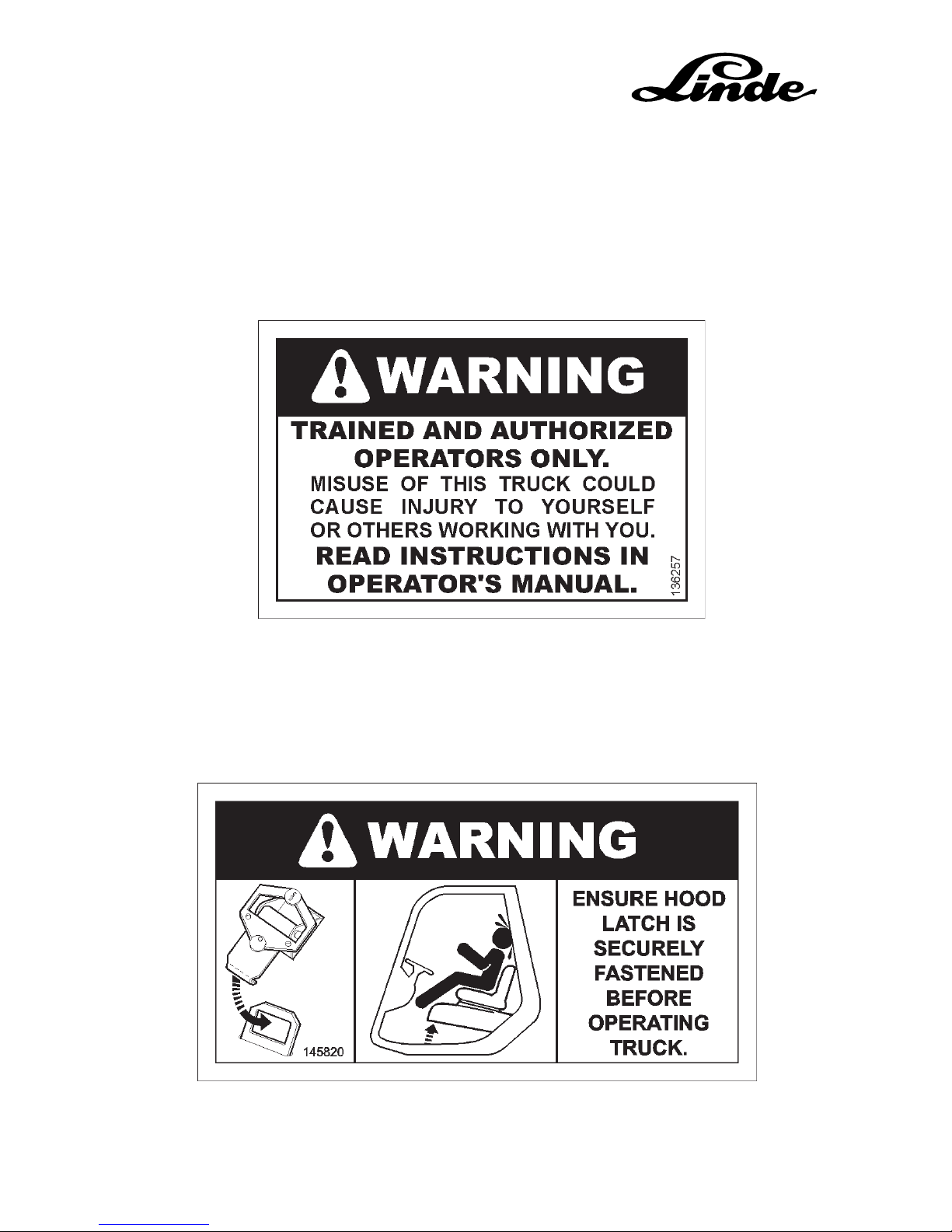
Trained Operator Warning Decal
This decal reinforces the requirement that only trained and authorized
personnel are to operate the truck.
Hood Latch Warning Decal
This decal reinforces that the Operator should verify that the Hood Latch is
securely fastened before operating the truck.
Page 27

27
SAFETY TIPSSAFETY TIPS
SAFETY TIPSSAFETY TIPS
SAFETY TIPS
OPERATOR WARNING AND SAFETY DECALS
(continued)
“Don’t Walk Under or Stand On Forks” Warning Decal
This decal is located on both sides of the Mast Uprights and warns both the
Operator and any pedestrians not to stand on or walk under a raised load at
any time.
Page 28

28
SAFETY TIPSSAFETY TIPS
SAFETY TIPSSAFETY TIPS
SAFETY TIPS
OPERATOR WARNING AND SAFETY DECALS
(continued)
Brake Warning Decal
This decal reinforces that the Operator should engage the Parking Brake
lever whenever necessary, as it is not automatically applied.
Personnel Warning Decal
This decal reinforces that the Operator should never use the Forks to lift
personnel for any reason.
Page 29

29
SAFETY TIPSSAFETY TIPS
SAFETY TIPSSAFETY TIPS
SAFETY TIPS
OPERATOR WARNING AND
SAFETY DECALS (continued)
Seat Belt / Tip-Over Warning Decal
This decal reinforces that the Operator should
read the Operator’s Manual and engage the Seat
Belt before operating the truck. It also instructs
the Operator on what to do in the event of a tipover of the truck.
Page 30

30
SAFETY TIPSSAFETY TIPS
SAFETY TIPSSAFETY TIPS
SAFETY TIPS
NOTES:
Page 31

31
SAFETY TIPSSAFETY TIPS
SAFETY TIPSSAFETY TIPS
SAFETY TIPS
NOTES:
Page 32

©2002 Linde Lift Truck Corporation
2450 West 5th North Street
Summerville, S.C. 29484
PHONE (843) 875-8000 FAX (843) 875-8329
LINDE LIFT TRUCK CORP.
A MEMBER OF THE LINDE GROUP
Page 33

With Diesel Engine
353 804 3001 GB
Linde Fork Lift Truck
H 50 - 02 / H 60 - 02 / H 70 - 02
H 80 - 02 / H 80/900 - 02
Operating Instructions
0702
d353-02/33
Page 34

Page 35

Linde - Your Partner
Linde AG Linde Material Handling Division
Linde, an enterprise operating
worldwide in the investment
and service sector, is one of
the large industrial enterprises in the EC with its three
business segments and six
divisions.
The Linde Material Handling
division is a leading manufacturer of industrial trucks and
hydraulics. It includes eight
manufacturing plants in the
Federal Republic of Germany ,
France and Great Britain, as
well as subsidiaries and branches in all economically important countries.
Linde industrial trucks enjoy a
worldwide reputation - thanks
to their high quality in engineering, performance and service.
Werk II, Aschaffenburg-Nilkheim
Werk I, Aschaffenburg
Lansing Linde Ltd., Basingstoke
Fenwick-Linde, Châtellerault
Werk III, Kahl am Main
Linde Heavy Truck Division Ltd., Merthyr Tydfil
Page 36

2
353 804 3001.0702
Description
Your Linde lift truck
offers the best in economy, safety and driving convenience.
Therefore it lies mainly in the hands of the operator to
preserve the qualities of the trucks for a long and profitable
service life and to make full use of their benefits on the job.
These operating instructions tell you all you need to know
about starting, operation, running, and servicing the truck.
For maintenance and repair work not described in these
operating instructions special technical skill and knowledge,
measuring equipment and special worshop tools are often
required. Please contact your authorised Linde dealer for this
service.
Only qualified persons authorised by Linde are allowed to
service the trucks.
For some options, follow the operating instructions supplied
with that equipment. Follow the operating instructions for your
truck and perform the services specified in the inspection and
maintenance schedule regularly, on time and with the specified oils and lubricants.
Keep a record of all maintenance services, otherwise your
warranty may become void.
The terms “front“, “rear“, “left“ and “right“ refer to the position
in which the item is installed in the truck, looking in the forward
travel direction of the truck.
Authorised applications
Your Linde truck is designed for transporting and lifting the
loads specified in the load capacity diagram.
In particular, we refer to the VDMA booklet "Rules for the
Normal and Proper Use of Industrial Trucks" supplied with
this manual, to accident prevention rules of your employer's
liability insurance and to the requirements of traffic regulations.
The rules for the normal and proper use of industrial trucks
must be followed under all circumstances by the responsible
persons, in particular by the operators and service personnel.
The user, and not the manufacturer Linde, is liable for any
hazards arising from unauthorised applications.
If you wish to use the truck for applications not mentioned in
these guidelines, please first contact your Linde distributor
before supplementing or retrofitting it for this purpose.
No changes, in particular no conversions or retrofits, may be
made to the truck without the prior permission of the manufacturer.
Page 37

3
353 804 3001.0702
Technical note
These operating instructions or excerpts thereof may only be
copied, translated or used by third parties after prior written
approval by the manufacturer.
Linde pursues a policy of continuous improvement in the
design and construction of its products. As a result, the
illustrations and technical details regarding design, equipment and engineering of trucks are subject to change or
modification as a result of technological progress.
Therefore, no liability based on the specifications, illustrations and descriptions contained in this operating manual will
be accepted.
Please submit all enquiries concerning your truck and all
orders for spare parts to your authorised distributor, making
sure to state your correct shipping address.
For repairs use only genuine Linde spare parts to ensure that
your truck will retain its original technical standard.
When ordering spare parts, specify the part numbers and also
the
Lift truck model: __________________________________
Manufacturer’s number/year built: ____________________
Takeover date: ___________________________________
Also state the manufacturer’s number of the engine and mast
when ordering parts for these assemblies.
Engine number: __________________________________
Mast number: ____________________________________
Mast lift height: ________________________________mm
When taking over the fork truck, transfer the data from the
assembly type plates into this manual.
Takeover inspection
Every fork lift truck undergoes careful inspection before
leaving the factory, in order to make sure that it will be in
satisfactory condition and fully equipped as ordered when
delivered to the customer. Authorised distributors are under
obligation to re-inspect the truck before delivery and to hand
it over in proper order.
With a view to avoiding later complaints, we request you to
check the condition of the truck, to make sure that it is
equipped as ordered, and to acknowledge the proper handing/taking over of the truck in the manufacturer’s certificate of
conformity.
The following technical documents belong to each fork lift
truck:
1 Operating instructions
1 Manufacturer’s declaration of conformity
(manufacturer declares that the industrial truck conforms
to the EC directives for machines)
1 Rules for the Normal and Proper use of Industrial Trucks
(VDMA)
Wishing you satisfactory operation,
Linde AG
Linde Material Handling Division
Aschaffenburg
Description
Page 38

4
353 804 3001.0702
Page 39

5
353 804 3001.0702
1
2
5
4
3
7
8
6
1 Manufacturer’s plate
2 Manufacturer
3 CE symbol
(The symbol certifies that the EC directives for machines
and all applicable guidelines are fulfilled.)
4 Serial number / year built
5 Weight of empty truck
6 Battery voltage
7 Rated capacity
8 Type
9 Lift mast number (stamped)
10 Chassis number (stamped on side)
11 Working hydraulics pump plate
12 Power steering pump plate
13 Traction hydraulics pump plate
14 Engine type plate
Type plates Description
1
9
10
11
12
13
14
d353-2/095
Page 40

6
353 804 3001.0702
Innovative technology,
easy and ergonomic operation,
energy-efficient, environment- and maintenance-friendly,
solid manufacture and
because almost all spares are of our own manufacture they
are readily available!
The success of a company
with about 9600 employees in eight manufacturing sites.
Fork lift truck models H 50 / H 60 / H 70 / H 80 / H 80/900 with Diesel engine Description
The driver’s position and operating features are designed using
the latest research in ergonomics. Each operating element is
designed in regard to position and operation to ensure the
driver’s convenience guaranteeing effortless and safe operation.
Of course, this also includes the easy hydrostatic power
steering with a kick-back safety, the proven double-pedal
travel control - forward with the right pedal, reverse with the
left - and only one main lever for all mast functions.
d353-02/33
Page 41

7
353 804 3001.0702
PagePagePage
Table of contents Description
Description .....................................................................2
Authorised applications ........................................................ 2
Technical note...................................................................... 3
Takeover inspection .............................................................3
Type plates........................................................................... 5
Technical data ................................................................... 10
Noise emission levels ....................................................... 12
Frequency characteristic for human body vibrations ...... 12
Technical description........................................................13
Engine ............................................................................13
Hydraulic system ........................................................... 13
Technical description .................................................... 13
Operation .......................................................................13
Lift mast ..........................................................................13
Brakes ............................................................................13
Steering .......................................................................... 13
Electrical system ............................................................ 1 3
General view of truck ........................................................1 4
Controls and indicators ..................................................... 15
Composite instrument .......................................................17
Beginning operation ................................................ 1 8
Safety rules ........................................................................ 1 8
Important safety information ............................................. 1 8
Handling fuels and lubricants .......................................... 18
Accident prevention check ................................................ 19
Operation of industrial trucks in the plant area................1 9
Diesel engine emissions .................................................. 19
Particle filter system inspection (option) .......................... 1 9
Running-in instructions.....................................................19
Services prior to first operation ......................................... 19
Daily checks ...................................................................... 19
Daily checks and servicing before operation .................. 20
Opening the bonnet .......................................................... 20
Closing the bonnet ............................................................ 20
Check the fuel level .......................................................... 20
Refuelling ..........................................................................2 1
Check the engine oil level ................................................ 2 1
Check the header tank coolant level ................................ 21
Check the tyre inflation pressure ...................................... 22
Applying the seat belt .......................................................2 3
Opening the seat belt........................................................2 3
Adjusting the operator seat ............................................... 23
Starting the engine ............................................................ 24
Cold start ........................................................................... 2 5
Stopping the engine ......................................................... 25
Malfunctions during operation ..........................................25
Operation ...................................................................... 26
Driving ............................................................................... 26
Driving forward .............................................................. 26
Reversing....................................................................... 2 6
Reversing the direction of travel ................................... 2 6
Stopping .........................................................................2 6
Single-pedal model .......................................................... 27
Steering .............................................................................30
Brakes................................................................................ 30
Service brake ................................................................. 3 0
Parking brake ................................................................. 30
Applying the parking brake ........................................... 3 0
Releasing the parking brake ......................................... 30
Central-lever control of lifting device and attachments ... 31
Tilting the mast forward .................................................3 1
Tilting the mast back......................................................3 1
Lifting the fork carriage ..................................................3 1
Lowering the fork carriage ............................................ 31
Operating the attachments ............................................ 3 1
Operating the sideshift .................................................. 31
Operating the clamp ...................................................... 31
Single-lever control of lifting device and attachments .....3 2
Installation of additional equipment ................................. 33
Turning on the lighting ......................................................3 3
Turning on the hazard warning light ................................ 3 3
Turning on the front working lights ...................................3 3
Turning on the working light (at rear)...............................3 3
Operating the intermittent front windscreen wiper ...........3 3
Operating the front windscreen wiper .............................. 3 3
Operating the front windscreen washer ........................... 3 3
Intermittent switch for rear and top windscreen wiper .....3 3
Operating the rear windscreen and top screen wipers ... 33
Operating the rear windscreen and top screen washer ..3 3
Operating the directional indicator lights ......................... 33
Turning on the dome light.................................................3 3
Heater ................................................................................3 4
Controls .......................................................................... 3 4
Fan motor fuse ...............................................................34
Operating the horn............................................................ 34
Check fuses, renew if required ......................................... 35
Before lifting a load ........................................................... 36
Loading ............................................................................. 3 7
Adjusting the fork spread ..................................................3 7
Loading ............................................................................. 3 7
Transporting a load ........................................................... 38
Depositing a load .............................................................. 38
Before leaving the lift truck unattended ........................... 3 8
Transport ........................................................................... 3 9
Transport with lorry or low-bed semi-trailer..................3 9
Hoisting the truck ..............................................................3 9
Hoisting the truck with a crane .........................................3 9
Hoisting the truck, wheel change ..................................... 40
Hoisting the truck with lifting eyes ....................................40
Wheel change ................................................................... 40
Mast removal, trailer coupling .......................................... 41
Mast removal .....................................................................4 1
Securing the moveable overhead guard ......................... 4 1
Trailer coupling ................................................................. 41
Towing instructions ........................................................... 42
Towing............................................................................ 42
Towing procedure ..........................................................4 2
Releasing the disc brake ............................................... 4 2
Opening the hydraulic by-pass valve ........................... 4 2
After towing .................................................................... 4 2
Making the brakes operational again ........................... 42
Emergency exit for trucks with rear windscreen ..............43
Taking the truck out of operation ......................................44
Measures before taking the truck out of operation .......... 4 4
Putting the truck back into operation ................................4 4
Maintenance ...............................................................44
General information .......................................................... 44
Servicing the mast and the front part of the truck ............45
Securing the mast against tilting back .............................4 5
Standard mast ................................................................... 45
Securing the raised standard mast .................................. 4 5
Maintenance after the first 50 service hours ....................4 5
Inspection and maintenance schedule ............................ 46
Page 42

8
353 804 3001.0702
Page 43

9
353 804 3001.0702
PagePagePage
Table of contents Description
Inspection and maintenance as required...... 48
Cleaning the lift truck ........................................................4 8
Cleaning and spraying the mast chain ............................ 4 8
Cleaning the air filter ......................................................... 4 9
Cleaning with compressed air ...................................... 49
Emptying the dust bowl in the air filter cover ...................5 0
Replacing the safety element ........................................... 5 0
Clean the pre-filter ............................................................ 50
Regenerate the particle filter ............................................5 1
Check wheel fastener for tightness .................................. 5 2
Check the tyres for damage and foreign objects ............. 5 2
Lubricate the steer axle, mast and tilt cylinder bearings . 5 2
Clean the radiator and engine oil, hydraulic oil and
fuel cooler, check for leaks ............................................5 3
Clean with compressed air ............................................ 5 3
Clean with a cold cleaner .............................................. 5 3
Drain the water separator in the fuel system ...................5 4
Check seat belt for condition and operation ....................5 5
500-hour inspection and maintenance...........5 6
Clean and lubricate the steer axle ...................................5 6
Grease the mast pivots .....................................................5 6
Grease the tilt cylinder and overhead guard pivots .........5 6
Check the engine mounting, movable overhead guard,
steer axle and drive axle hub differentials for tightness... 57
Check the forks and fork quick-releases .......................... 57
Check the mast, lift chains and stops for condition,
operation and security ................................................... 5 7
Adjust the lift chains .......................................................... 58
Lubricate with chain spray................................................ 58
Check the pre-tension of double hoses if attachments
are fitted .........................................................................5 8
Check and oil other pivots and joints ............................... 5 8
Check the engine cooling system for leaks ..................... 5 9
Check and oil the pedals, accelerator and
engine control linkage ................................................... 59
Renew the engine oil (at least every 12 months) ............ 6 0
Drain the engine oil .......................................................... 60
Renew the engine oil filter................................................ 60
Add engine oil ................................................................... 61
Check the hydraulic oil level ............................................ 6 1
Check the coolant concentration ...................................... 6 2
Check the particle filter system.........................................6 2
Check and tension V-belt drives ...................................... 6 3
Tighten V-belt drives .........................................................6 3
Drain the water separator in the fuel system ...................6 3
Clean the radiator, hydraulic oil and fuel cooler .............6 4
Clean with compressed air ............................................ 6 4
Clean with a cold cleaner .............................................. 6 4
Renew the drive axle hub differential oil and clean
the magnetic plug .......................................................... 64
Check the condition and security of electric cables,
connectors and cable connections ...............................6 5
Check the condition, electrolyte level and
specific gravity of the battery......................................... 65
1000-hour inspection and maintenance........ 66
Renew the hydraulic pressure, suction and
breather filters ................................................................ 66
Renew the pressure filter ..............................................6 6
Renew the suction filter .................................................6 6
Renew the breather filter............................................... 67
Renew the fuel filter canister ............................................6 7
Check the engine mounting for condition and tightness ..... 67
Renew and tension the V-belt drive .................................6 8
Check the exhaust system for leaks and tightness ......... 69
Check the hydraulic system, hydraulic pumps,
valves and lines for leaks .............................................. 69
Renew the air filter element, check the vacuum switch ...7 0
Check the parking brake ................................................... 7 0
Check the drive axle hub differential oil level
and for leaks .................................................................. 7 1
Check the particle filter system.........................................7 1
2000-hour inspection and maintenance........ 72
Check the particle filter system.........................................7 2
Check valve tip clearances ............................................... 7 2
Renew the safety element ................................................ 7 3
3000-hour inspection and maintenance........ 74
Renew the hydraulic oil .................................................... 74
Drive axle hub differential: Renew oil and
clean the magnetic plug ................................................ 75
Renew the coolant ............................................................ 7 6
Inspection and maintenance data .................................... 7 7
Fuel and oil recommendations ......................................... 78
Engine oils ..................................................................... 78
Diesel fuel ...................................................................... 79
Hydraulic oil ................................................................... 79
Gear oil .......................................................................... 79
Grease ............................................................................ 79
Coolant .......................................................................... 7 9
Battery grease ................................................................ 79
Chain spray ....................................................................7 9
Troubleshooting guide (Diesel engine) ........................... 80
Troubleshooting guide (hydraulic system) ...................... 83
Electric circuit diagram ...................................................... 8 4
Electric circuit diagram (Options) .....................................8 7
Particle filter wiring diagram .............................................9 0
Hydraulic circuit diagram ..................................................9 2
Index .................................................................................. 94
Page 44

10
353 804 3001.0702
Technical data Description
Notes:
1) Additional lifting mast heights; see table.
2) Aditional optional tyres upon request.
3) Values in brackets for double wheels 8.25 - 15/18 PR.
4) 1718 mm for double wheels 8.25 - 15.
5) With a free lift of 150 mm.
6) On short slopes, when crossing obstacles (refer to
section "Travel").
CharacteristicsWeightWheels and TyresDimensionsPerformanceIC engineOthers
1.1 Manufacturer (see page 1)
1.2 Model designation
1.3
Power unit: battery, diesel, petrol, LPG, mains power
1.4 Operation: manu., pedest., stand-on, seated, ord. pic.
1.5 Load capacity Q [t]
1.6 Load centre c [mm]
1.8 Axle centre to fork face x [mm]
1.9 Wheelbase y [mm]
2.1 Service weight [kg]
2.2 Axle load with load, front/rear [kg]
2.3 Axle load without load, front/rear [kg]
3.1
Tyres, front/rear (SE = CS superelastic, L = pneum.)
3.2 Tyre size, front
3.3 Tyre size, rear
3.5 Wheels, number front/rear (x = driven)
3.6 Track width, front b10 [mm]
3.7 Track width, rear b11 [mm]
4.1 Mast/fork carriage tilt, forward/backward degrees
4.2 Height of mast, lowered h1 [mm]
4.3 Free lift h2 [mm]
4.4 Lift h3 [mm]
4.5 Height of mast, extended h4 [mm]
4.7 Height of overhead guard (cabin) h6 [mm]
4.8 Height of seat/stand-on platform h7 [mm]
4.12 Tow coupling height h10 [mm]
4.19 Overall length l1 [mm]
4.20 Length to fork face l2 [mm]
4.21 Overall width b1/b2 [mm]
4.22 Fork dimensions s/e/l [mm]
4.23 Fork carriage to DIN 15173, class/form A, B
4.24 Width of fork carriage b3 [mm]
4.31 Ground clearance, mast m1 [mm]
4.32 Ground clearance, centre of wheel base m2 [mm]
4.33
Aisle width with pallets 1200x1000 across forks Ast [mm]
4.34 Aisle width with pallets 800x1200 along forks Ast [mm]
4.35 Turning radius Wa [mm]
4.36 Min. distance between the centres of rotation b13 [mm]
5.1 Travel speed, with/without load km/h
5.2 Lifting speed, with/without load m/s
5.3 Lowering speed, with/without load m/s
5.5 Tractive force, with/without load, 60 minute rating N
5.7 Climbing ability with/without load, 30 minute rating % 6)
5.9 Acceleration time with/without load (first 10 m) s
5.10 Service brake
7.1 Manufacturer of engine/type
7.2 Engine rated power to ISO 1585 kW
7.3 Rated rpm RPM
7.4 Number of cylinders / cc n/cc
7.5 Fuel consumption to VDI l/h kg/h
8.1 Type of drive control
8.2 Working pressure for attachments bar
8.3 Oil quantity for attachments l/min
8.4 Mean noise level at driver's ear dB (A)
8.5 Towing coupling, design/type DIN, no.
to VDI 2198
Data Sheet for Material Handling Equipment
VDI 2198
DFG
June 1999
Fork Lift Trucks
Designation VDI 2198
H 50 D
Diesel
seated
5.0
600
590
2160
9300
12200 / 2100
4450 / 4850
L (SE)
300 - 15/22 PR 2)
8.25 - 15/18 PR 2)
2x (4x) / 2 3)
1594 4)
1600
6 / 10
2730 1) 5)
150
3550 1)
4450 1)
2714
1432
810
4590
3390
1894 (2262) / 1850 3)
60 x 130 x 1200
4 A
1800
202
245
4850
5050
3060
975
22 / 22
0.53 / 0.53
0.50 / 0.50
61000 / 31000
45 / 28
4.7 / 4.3
hydrostatic
KHD / BF 6M 1012
85
2200
6 / 4800
5.3
hydrostatic transmission
260
-
-
-
H 60 D
Diesel
seated
6.0
600
590
2160
9550
13770 / 1780
4470 / 5080
L (SE)
355/65 - 15/24 PR 2)
8.25 - 15/18 PR 2)
2x (4x) / 2 3)
1594 4)
1600
6 / 10
2730 1) 5)
150
3550 1)
4450 1)
2714
1432
810
4590
3390
1948 (2262) / 1850 3)
60 x 130 x 1200
4 A
1800
202
245
4850
5050
3060
975
22 / 22
0.53 / 0.53
0.50 / 0.50
57000 / 33000
35 / 27
5.2 / 4.7
hydrostatic
KHD / BF 6M 1012
85
2200
6 / 4800
5,6
hydrostatic transmission
260
-
-
-
H 70 D
Diesel
seated
7.0
600
600
2160
10760
15650 / 2110
4770 / 5990
L (SE)
8.25 - 15/18 PR 2)
8.25 - 15/18 PR 2)
4x / 2
1748
1600
6 / 10
2730 1) 5)
150
3150 1)
4250 1)
2714
1432
810
4600
3400
2262 / 1850
70 x 150 x 1200
4 A
2180
202
245
4860
5060
3060
975
22 / 22
0.42 / 0.42
0.42 / 0.42
58000 / 35000
29 / 28
5.7 / 5.1
hydrostatic
KHD / BF 6M 1012
85
2200
6 / 4800
5.9
hydrostatic transmission
260
-
-
-
H 80 D
Diesel
seated
8.0
600
600
2160
11500
17160 / 2340
4730 / 6770
L (SE)
8.25 - 15/18 PR 2)
300 - 15/18 PR 2)
4x / 2
1748
1550
6 / 10
2730 1) 5)
150
3150 1)
4250 1)
2714
1432
810
4600
3400
2262 / 1850
75 x 150 x 1200
4 A
2180
202
245
4860
5060
3060
975
22 / 22
0.42 / 0.42
0.42 / 0.42
58000 / 35000
26 / 27
6.2 / 5.3
hydrostatic
KHD / BF 6M 1012
85
2200
6 / 4800
6.2
hydrostatic transmission
260
-
-
-
H 80 D/900
Diesel
seated
8.0
900
630
2510
12400
18200 / 2200
5400 / 7000
L (SE)
8.25 - 15/18 PR 2)
300 - 15/18 PR 2)
4x / 2
1748
1550
6 / 10
2730 1) 5)
150
2750 1)
4150 1)
2714
1432
810
5590
3790
2262 / 1850
70 x 200 x 1800
4 A
2180
202
240
5175
5375
3345
975
22 / 22
0.42 / 0.42
0.42 / 0.42
58000 / 42000
-
6.2 / 5.3
hydrostatic
KHD / BF 6M 1012
85
2200
6 / 4800
6.7
hydrostatic transmission
260
-
-
-
Page 45

11
353 804 3001.0702
Lifting capacity diagrams:
Safety distance “a” = 200 mm
Load capacities apply for SE tyres.
Mast and lifting height H 50, H 60 (in mm)
Lifting height h3 3550 4150 4550 5250 6050
Mast retracted (with 150 mm free lift for standard) h1# 2730 3030 3230 3580 3980
Mast extended h4 4450 5050 5450 6150 6950
Mast and lifting height H 70, H 80 (in mm)
Lifting height h3 3150 3750 4150 4850 5650
Mast retracted (with 150 mm free lift for standard) h1# 2730 3030 3230 3580 3980
Mast extended h4 4250 4850 5250 5950 6750
Mast and lifting height H80/900 (in mm)
Lifting height h3 2750 3350 3750 4450 5250
Mast retracted (with 150 mm free lift for standard) h1# 2730 3030 3230 3580 3980
Mast extended h4 4150 4750 5150 5850 6650
Technical data Description
Page 46

12
353 804 3001.0702
Noise emission levels
Determined in a test cycle in accordance with EN 12053 from
the weighted values in the operating modes DRIVING, LIFTING, IDLING.
Noise level at driver’s station
H 50 - H 80 L
PAZ
= 78 dB (A)
Uncertainty KPA= 4 dB (A)
Sound level at driver’s place
While lifting LPa= 8 0 dB (A)
While idling LPb= 6 5 dB (A)
While driving LPc= 8 3 dB (A)
Uncertainty KPA= 4 dB (A)
Acoustic power level
H 50 - H 80 L
WAZ
=100 dB (A)
Uncertainty KWA= 2 dB (A)
Acoustic power level
While lifting LWa=101 dB (A)
While idling LWb= 8 7 dB (A)
While driving LWc=105 dB (A)
Uncertainty KWA= 2 dB (A)
Guaranteed acoustic power level
Acc. to directive 2000/14/EC LWA=105 dB (A)
The directive legally requires this information. This value has
been calculated from the acoustic power levels for ”Lifting”
and ”Driving” and is only be used as a comparable value for
different trucks. For the determination of the real environmental
noise stress this value is less appropriate, as it is not
representative of normal truck operation, which includes
”Idling”.
NOTE
Higher or lower noise emissions can exist during operation of the truck, for example due to type of operation,
environmental influences and additional noise emission
sources.
Technical data Description
Frequency characteristic for human body
vibrations (preliminary values as only a
draft standard is available)
The values are determined in conformance with prEN 13059
on trucks with standard equipment according to the technical
data sheet (driving over test course with bumps).
Frequency characteristic acc. to EN 12096
Measured frequency characteristic a
w.zs
= 0.8 m/s²
Uncertainty K = 0.3 m/s²
Frequency characteristic given for hand and arm vibrations
Frequency characteristic < 2.5 m/s²
NOTE
The frequency characteristic for the human body can not
be used to determine the actual frequency load during
operation. This load depends on the working conditions
(condition of roadway, type of operation, etc) and must
therefore be determined at the site, if necessary.
The specification of hand and arm vibrations is required
by law, even if the values, as in this case, do not indicate
any danger.
Page 47

13
353 804 3001.0702
The 353 fork lift truck series is designed for loading and
spotting loads of up to 5 tons with the H 50, of up to 6 tons with
the H 60, of up to 7 tons with the H 70 and 8 tons with the
H 80 with a load centre distance of 600 mm.
The H 80 / 900 is designed for loading and spotting loads of
up to 8 tons with a load centre distance of 900 mm.
The trucks have a compact and low profile design.
The low centre of gravity and the optimum distribution of
weight ensures optimum stability under all operating conditions.
Engine
A water-cooled, 6-cylinder supercharged Diesel engine with
direct fuel injection is installed as power unit. It drives the
hydraulic pumps of the truck at load-dependent speed.
The combustion air is cleaned by dry air filter with a paper
element.
Hydraulic system
The drive system consists of one variable-displacement pump
for driving the two traction hydraulics variable-displacement
motors, one hydraulic pump each for the working and steering
hydraulics, and one hydraulic pump for boost pressure.
The variable-displacement hydraulic motors in the drive units
are supplied with pressure by the variable-displacement
pump. They power the traction wheels via two lateral drive
axle hub differentials.
Operation
The hydraulic pump and the speed are simultaneously controlled by the forward and reverse accelerator pedals. The
truck speed can be regulated by the hydrostatic power source
from a standstill up to the maximum speed with infinitely
variable control in both directions. The double pedal control
permits easy as well as safe and time-saving handling of the
lift truck.
Both hands are always free for steering and control of the
work movements. The net result is quick reversing and
energy-saving stacking.
There is only one control lever (main control lever) for controlling the work motions lifting, lowering and tilting. Additional
control levers are supplied for the operation of supplementary
attachments.
Lift mast
Overhead tilt cylinders are fitted for sensitive tilting and for
mast stabilisation. The LTS (Linde Torsion Support), also
functioning as overhead guard, ensures high strength against
torsion, i.e. easy working due to reduced torsional vibrations
of the mast and so a long service life.
For lifting the inner mast, there are two lift cylinders mounted
on the outer upright channel.
The fork carriage is lifted by two flyer chains running at the
inner upright channel.
Brakes
The hydrostatic transmission is used as service brake. The
two multiple disc brakes integrated in the compact axle are
utilised as a parking brake.
When the engine is stopped, the multiple disc brakes are
applied = automatic braking.
The brake pedal is also used as parking brake. To park the
truck, lock the brake pedal mechanically.
Steering
The steering is a hydrostatic power steering system, which
turns the rear wheels with the steering wheel via the steer
cylinder.
The steering system can also be operated when the engine is
stopped, but a greater effort is required to turn the steering
wheel.
Electrical system
The electrical system is supplied by a three-phase current
generator with 12 VDC. For starting the engine, a
12-volt battery is installed.
Technical description Description
Page 48

14
353 804 3001.0702
1 Steering wheel
2 Tilt cylinder
3 Driver’s seat
4 Cabin*
5 Counterweight
6 Bonnet
7 Steering axle
8 Electrical system cover
9 Foot steps
10 Left drive axle hub differential
11 Fork carriage
12 Lift cylinder
13 Forks
14 Fork quick-releases
15 Lift chain
16 Lifting mast
17 Control console
* Option
General view of truck Description
d353-02/34
12 3
4
5
6
7
89
1011
12
13
14
15
16
17
Page 49

15
353 804 3001.0702
1
23 4
56
7
8
9
10
1112
13
14
15
16
17
18
d353-02/35
1 Toggle switches for supplementary functions*
2 Parking brake lever
3 Steering wheel/hydrostatic power steering
4 Horn button
5 Ignition switch and key switch
6 Toggle switches for supplementary functions*
7 Composite instrument
8 Air outlet*
9 Control lever for supplementary hydraulics (attachments)*
10 Label for supplementary hydraulics*
11 Notice label
12 Load capacity diagram
13 Load capacity plate (attachment)*
14 Symbol label for working hydraulics
15 Control lever for working hydraulics
16 Forward accelerator pedal
17 Brake pedal
18 Reverse accelerator pedal
* Option
Controls and indicators Description
Page 50

16
353 804 3001.0702
Page 51

17
353 804 3001.0702
1
2
6
5
7
9
3
13
d353-2/071
4
10
8
11
12
Composite instrument Description
Indicator element Function Possible fault(s)
The composite instrument contains the following control and
indicator elements:
1 Hour meter
2 Hour meter on indicator light
3 Coolant temperature control indicator, coolant level indi-
cator
4 Particle filter warning light
5 Hydraulic oil temperature warning light
6 Engine oil pressure warning light
7 Pre-heating indicator light
8 Flasher indicator light
9 Battery charge indicator light
10 Fuel level warning light
11 Air filter restriction indicator light
* Option
Hour meter (1). The row of figures (13)
shows the full service hours, the last
figure (12) 1/10 of an hour
Hour meter ON indicator light (2)
Coolant temperature control indicator, coolant level indicator (3)
Particle filter warning light* (4)
Hydraulic oil temperature warning
light (5)
Engine oil pressure warning light (6)
Pre-heating indicator light (7)
Flasher indicator light* (8)
Battery charge indicator light (9)
Fuel level warning light (10)
Air filter restriction indicator light (11)
Indicates lift truck service hours. The
display serves as reference for
elapsed working hours and for the
required inspection and maintenance
activities
Indicates that the hour meter is running
Indicates that the coolant temperature is too high or that the coolant level is too low
Indicates that the particle filter must
be regenerated
Monitors the hydraulic oil temperature
Indicates low oil pressure of engine
lubrication
It is illuminated if the pre-heating
function is on
Indicates operation of flasher unit
when direction indicator is on
Indicates malfunctions in the electrical system
Indicates a fuel reserve of approx. 8.0
litres.
Indicates excessive accumulation of
dirt on air cleaner element
NOTE
The elapsed service hours should be recorded when replacing a defective hour
meter. Record data on durable tape and
affix next to hour meter
- Fan V-belt slack
- Dirt on the radiator
- Leak in the cooling system
- Low coolant level
- Regenerate the particle filter
- Dirt on oil cooler
- Oil filter blocked
- Oil level in hydraulic system is too low
- Oil not as specified
- Low oil level in crankcase
- Engine is overheating
- Oil not as specified
- Internal leakage in lubricating system
- V-belt broken or slipping
- Cables broken
- Alternator faulty
- Regulator or relay faulty
- Air filter element restricted
Page 52

18
353 804 3001.0702
The responsible persons, particularly the truck operator and
servicing personnel, must be instructed in the safety guidelines for the normal and proper use of industrial trucks
included with these operating instructions.
The employer must ensure that the operator has understood
all safety informations.
Please observe the guidelines and safety rules therein for
example:
- information on the operation of industrial trucks
- rules for roadways and work areas
- rights, duties and safety rules for the operator
- operation in special areas
- information related to starting, driving and braking
- service and repair information
- recurrent inspections, accident prevention check
- disposal of greases, oil and batteries
- remaining risks.
The operator (employer) or the responsible person must
ensure that all the guidelines and safety rules applicable for
your truck are observed.
When instructing a trained operator, acquaint him with the
- special features of the lift truck (double-pedal control,
main control lever, brake pedal)
- optional attachments
- special operating and working area characteristics,
by training and practicing driving, shifting and steering operations until they are completely mastered.
Only then start to practice shelf-stacking.
The stability of the truck in the work area is ensured if
employed properly. Should the truck tip over during an
unauthorised application or due to incorrect operation, always follow the instructions depicted below.
Safety rules Beginning operation
Handling fuels and lubricants
Always handle fuels and lubricants as required and
as specified by the manufacturer.
Only store fuels and lubricants in approved containers at
specified storage places. As they could be inflammable, do
not contact them with hot objects or a naked flame.
Only use clean containers when replenishing fuels and
lubricants.
Follow the manufacturer’s safety and disposal instructions
when using fuels and lubricants and cleaning compounds.
Avoid spilling fuels and lubricants. Remove any spillage
immediately with a suitable binding agent and dispose of as
specified.
Also dispose of used or contaminated fuels and lubricants as
specified.
Follow laws and regulations.
Clean the area surrounding the part in question before
lubrication, filter renewal or repairs in the hydraulic system.
Discard parts in a way friendly to the environment.
CAUTION
Do not allow hydraulic oil under pressure, for
example at a leak, to penetrate the skin. Medical
aid is required if such an injury occurs.
CAUTION
Improper handling of coolants and coolant additives puts your health and the environment at
risk.
Important safety information
The precautions WARNING, CAUTION, ATTENTION and
NOTE in this manual are provided to indicate special dangers
or unusual information requiring special identification:
WARNING
indicates hazards that may result in personal
injury or death and/or substantial damage to the
product.
CAUTION
indicates hazards that may result in personal
injury and/or substantial damage to the product.
ATTENTION
indicates hazards that may result in damage to
or destruction of the product.
This note is found on various positions of the
truck where special attention is required. Read
the appropriate section of your operating instructions.
Further warning notices are also used for your safety. Please
observe the various symbols.
NOTE
identifies technical information requiring special attention because the connection may not even be obvious to
skilled personnel.
Lean away
Brace feetHold on tight
Don't jump
In case of tip-over
Stay
buckled up
WARNING
Follow these
instructions
E335-2/149
Page 53

19
353 804 3001.0702
Accident prevention check
The accident prevention rules in some countries require that
the fork lift truck must be checked at least once a year for
proper working condition by trained personnel. Please contact your authorised distributor for this inspection.
Operation of industrial trucks in the plant
area
ATTENTION
Many plant areas are so-called limited public
traffic areas.
We advise you to check if your company liability insurance covers any damages occurring with your fork truck
against third parties on limited public traffic areas.
Diesel engine emissions
In Germany, fork trucks equipped with diesel engines must
conform to TRGS 554. According to this regulation, diesel
emissions are carcinogenic and they should, if at all possible,
not permeate the air of workplaces.
If trucks equipped with diesel engines are used in totally or
partially enclosed spaces, the labour protection authority
must first be notified. Appropriate notices must be posted in
the work areas (refer to TRGS 554 for an example).
Safety rules Beginning operation
Particle filter system inspection (option)
The responsible authorities require that particle filter systems
must be serviced every six months by an expert. Record the
inspection results in a “Diesel engine emission inspection
certificate“ and insert it in the logbook (e.g. accident prevention check book for the truck).
Running-in instructions
The lift truck can be operated at full speed directly. However,
avoid sustained high loads on the working hydraulic system
and the travel drive in the first 50 hours of operation.
During initial operation and after each wheel change, tighten
wheel nuts daily prior to starting operation until they are
seated firmly, i.e. until no further tightening is possible.
The opposite wheel fasteners for tightened to a torque of:
front and rear ............................................................600 Nm
NOTE
Observe the tightening instructions on the tag attached
to the steering column.
* A description of the service can be located in the alphabet-
ical index.
Services prior to first operation
*
- Check the engine oil level
- Check the header tank coolant level
- Refuelling
- Check condition, electrolyte level and specific gravity of
the battery
- Check the tyre inflation pressure
- Check the wheel fasteners for tightness
- Check the hydraulic oil level
- Check the drive axle hub differential oil level and for leaks
- Braking system
- Steering system
- Operation of lifting device and attachments
- Regenerate the particle filter (option)
Daily checks
*
- Check the engine oil level
- Check the header tank coolant level
- Check the fuel level
- Check the tyre inflation pressure
Page 54

20
353 804 3001.0702
4
1
d353-02/57
9
32
1
5
6
7
8
t352/83
d353-2/088
1
Opening the bonnet
- Lift the lever (9) and tilt the backrest (4) forward.
- Pull the seat adjustment lever (3) and slide the seat fully
forward.
- Unlock the bonnet lock (1) on the left and right side by
inserting the key (5) and turning it anti-clockwise.
- Open the rotary lever (6) and turn it anti-clockwise as far
as possible.
- Unhook the clip (7) from the bracket (8) and tilt it up.
- Open bonnet by tilting it back with the grip (2).
NOTE
The bonnet is held open by the gas-filled strut.
Closing the bonnet
- Close the bonnet.
- Hook the clip (7) of the left bonnet lock into the bracket (8).
- Turn the rotary lever (6) clockwise as far as possible.
- Turn the key (5) clockwise and remove it.
- Also lock the bonnet lock on the right.
Check the fuel level
The fuel level warning light (1) at the instrument panel goes
on when 8.0 litres of fuel remain in the tank.
Filling diesel fuel becomes necessary.
Daily checks and servicing before operation Beginning operation
Page 55

21
353 804 3001.0702
1
d353-02/01
3
d353-2/072
4
d353-2/089
1
2
Refuelling
CAUTION
Stop the engine before refuelling. No smoking or
naked flames when refuelling. Do not spill any
fuel and do not allow any fuel to come in contact with hot
parts. Follow the regulations for refuelling.
- Open the fuel filler cap (1) on the right side of the truck and
fill with clean diesel fuel.
Max. fuel capacity ............................................70.0 litres
ATTENTION
To avoid malfunctions caused by the injection
system sucking in air, do not allow the fuel tank
to become completely empty.
Check the engine oil level
ATTENTION
Follow the rules for handling fuel, lubricants and
coolant.
- Open the bonnet.
- Pull out the oil dipstick (1) at the engine on the right-hand
side of the truck.
- Wipe the dipstick with a clean cloth.
- Fully re-insert the dipstick and pull it out again.
- The oil level should be between the markings.
- If necessary, fill oil to the upper marking.
- To fill oil, first remove the oil filler cap (2).
- Refit and tighten the oil filler cap.
- Close the bonnet.
Check the header tank coolant level
ATTENTION
Follow the rules for handling fuel, lubricants and
coolant.
CAUTION
Do not open the reservoir cap (3) when the
reservoir is hot. The reservoir is pressurised.
Risk of scalding!
NOTE
If the indicator light (4) illuminates, it is possible that the
coolant level is low and coolant must be added.
- Remove the filler cap (3) from the radiator. The coolant
must be approx. 10 mm under the filler cap opening.
- Top up coolant in the reservoir as required.
- Refit and tighten the filler cap.
Daily checks and servicing before operation Beginning operation
Page 56

22
353 804 3001.0702
t353-02/16
1
Check the tyre inflation pressure
ATTENTION
A low tyre inflation pressure reduces the service
life of the tyres and the stability of the truck.
- Check the tyres for the specified inflation pressure.
- If necessary, inflate the tyres at the filler valves.
Inflate the tyres according to the informations on the front
label (1) and rear label.
Drive axle - single tyre
- H 50 300-15/22 PR ........ 10 bar
- H 50 / H 60 / H 70 355/65-15/24 PR ... 10 bar
Drive axle - twin tyres
- H 50 / H 60 / H 70 8.25-15/18 PR ......... 8 bar
- H 80 8.25-15/18 PR ....... 10 bar
Steer axle
- H 50 / H 60 / H 70 8.25-15/18 PR ......... 8 bar
- H 50 / H 80 300-15/18 PR .......... 6 bar
Daily checks and servicing before operation Beginning operation
Page 57

23
353 804 3001.0702
t352-03/01
1
2
3
45
t352 -03/02
6
7
8
9
11
10
CAUTION
The webbing should not be twisted, stuck or
knotted.
Protect the lock (4) and retractor (3) against foreign
particles and dirt.
NOTE
During operation of the truck (e.g. driving, lifting, etc.) the
operator should sit as far back as possible so that the
back contacts the backrest.
The automatic lock of the retractor allows sufficient
freedom of movement on the seat during normal operation of the truck.
Opening the seat belt
- Press the red button (5) on the belt buckle (4) to disengage
the belt.
- Return the tongue (2) back to the roller (3) by hand.
NOTE
A belt which returns too fast can trigger the automatic
lock when the tongue hits the enclosure. The belt can
then not be pulled out with the usual force.
Adjusting the operator seat
- For a horizontal adjustment of the seat, pull the adjust-
ment lever (8) out.
- Slide the seat in the guide rails either forward or back until
the optimum position in relation to the steering wheel,
accelerator pedals and control levers is obtained.
- Re-engage the lever.
- The adjustment of the backrest is by means of the backrest
adjuster (11).
- Push up and hold the backrest adjuster (11).
- Tilt the backrest forward or back until the position is
comfortable for the driver.
- Release the backrest adjuster (11).
Applying the seat belt
DANGER
The seat belt must always be applied during
the operation of the truck! The seat belt is only
for securing one person.
Drivercabs with closed, solid doors or bar-type doors
comply with the safety requirements for driver retaining
systems. We recommend the additional use of the seat
belt. The seat belt must be used if the truck is operated
with the doors open or removed.
NOTE
The automatic lock blocks the belt when the truck is
tilting heavily. The belt can then not be pulled out of the
retractor.
To unlock the automatic lock, carefully drive the truck off
the side slope.
- Pull the seat belt (1) out of the retractor with a smooth
movement.
- Place the seat belt over the thighs, not over the belly.
- Engage the tongue (2) in the lock (4).
- Check seat belt tension. The belt should be snug on the
body.
- Pull out the knob on the adjusting handwheel (10) and turn
the handwheel to set the cushioning to the weight of the
driver.
The adjustment range from 50 kg to 130 kg is visible at the
weight range indicator (9).
To increase the weight, turn handwheel clockwise.
To reduce the weight, turn handwheel anti-clockwise.
- To adjust the backrest upholstery* (6), move button (7)
until a comfortable sitting position is reached.
Turning the knob anti-clockwise makes the backrest upholstery arch out.
Turning the knob clockwise returns the backrest upholstery to its original position.
NOTE
Long sitting puts excessive strain on the spinal column.
Prevent strain with regular, light exercising.
* Option
Daily checks and servicing before operation Beginning operation
Page 58

24
353 804 3001.0702
d353-02/09
1
2
3
4
3
6
7
89
10
d353-2/073
Starting the engine
NOTE
If at all possible, avoid frequent engine starts and short
duty cycles so that the engine can reach its operating
temperature. Frequent cold starts increase engine wear.
NOTE
Close the engine cover. All control levers (2) must be in
neutral.
- Sit on the driver’s seat.
- Apply the seat belt.
- Place both feet on the accelerator pedals (3) (brake
pedal (4) locked, as the engine will only start with the brake
pedal locked).
- Insert the ignition key (1) into the heater starter switch and
turn from the zero position to position I. The electrical
system is now switched on.
- The coolant temperature warning light (6) comes on
briefly, the engine oil pressure warning light (8) and
battery charge warning light (10) are illuminated red. The
preheating indicator light (9) and the particle filter indicator
light (7) are illuminated yellow.
Starting the engine Beginning operation
- Hold the ignition key in position I until the yellow preheating indicator light (9) is extinguished, and then turn the key
further to position II.
- Operate the starter for a maximum of 20 seconds without
interruption. As soon as the engine starts, release the
ignition key.
- Should the engine not start, cease the starting procedure
and wait at least 1 minute before next starting attempt.
Should the engine also not start after the third starting
attempt, check whether the viscosity of the engine oil and
the Diesel fuel and the battery state of charge is as
specified in the operating instructions.
- As soon as engine is running, the warning lights for battery
charge and engine oil pressure should go out.
The engine speed is controlled automatically, depending on
the engine load.
NOTE
When the particle filter* warning light (7) is illuminated
refer to the section on regenerating the particle filter.
ATTENTION**
Observe the exhaust nozzle for about 5 s after
each engine start. If the exhaust gases are
continuously very smoky, stop ant take the truck out of
service.
Please contact your authorised dealer.
WARNING
Do not let the engine run in unventilated enclosed spaces. Risk of carbon monoxide poison-
ing!
NOTE
Do not let the engine warm up in idle.
The engine will be at operating temperature in a short
time if driven with a load and fast.
* Option ** Particle filter system only.
d3532300
1
Page 59

25
353 804 3001.0702
d353-02/11
2
3
4
3
1
1
2
34
5
6
d353-2/074
Cold start, Stopping the engine Beginning operation
Stopping the engine
NOTE
Do not stop the engine at full throttle.
- Release the accelerator pedals (3) and let the engine run
briefly without a load to balance the temperature.
ATTENTION
In addition, the danger exists that the turbo
charger crankshaft (engines with a turbo charger) can be damaged, because of the high revolutions
(approx. 100,000 RPM) and insufficient oil lubrication on
the crankshaft bearing.
- Turn the ignition key (2) to the zero position.
NOTE
Turning off the engine applies the brake.
- Set the parking brake lever (1) to the up position.
- Depress the brake pedal (4). The brake pedal will lock in
this position.
- Remove the ignition key when leaving the truck unattend-
ed.
Malfunctions during operation
ATTENTION
If one of the following indicator lights illuminates during
operation, shut off the engine immediately and eliminate
the malfunction. (see: Troubleshooting Guide)
- Coolant temperature warning light (1)
- Hydraulic oil temperature warning light (2)
- Engine oil pressure warning light (3)
- Battery charge indicator light (5)
NOTE
If air filter restriction indicator (6) lights up during operation, the air filter must be serviced.
When the particle filter warning light (4) is illuminated, the
particle filter* must be regenerated.
* Option
Cold start
NOTE
Starting at temperatures below 0 °C should be performed
with the accelerator pedal fully depressed in order to
obtain the extra amount of fuel required for starting.
This method of starting is recommended for below 0 °C
temperatures as it clearly improves the starting characteristics at low temperatures and/or with a weak battery.
Page 60

26
353 804 3001.0702
d353-02/12
2
3
4
1
CAUTION
Do not drive on slopes with gradients over
15 %, due to the specified minimum brake applications and truck stability characteristics. Before driving
on steeper slopes, you should first consult your distributor. The climbing ability rates given in the data sheet
were derived from the drawbar pull of the truck and they
apply only for crossing roadway obstacles and for minor
differences in height. Your driving style should always be
consistent with the conditions of the roadway (rough
surfaces, etc.), particularly hazardous work areas, and
the load.
CAUTION
When using rear view mirrors it should be noted
that the latter are only provided to monitor the
rear traffic area and that reversing is only allowed with a
direct view in the reverse direction of travel.
NOTE
When the particle filter* warning light (5) is illuminated
refer to the section on regenerating the particle filter.
Driving Operation
- Start the engine.
- Elevate the forks slightly and tilt the mast back.
- Push the parking brake lever (1) to the right to release the
brake pedal (3).
Driving forward
- Depress the right accelerator pedal (2) gently. The speed
of the truck depends upon how far the pedal is depressed.
NOTE
Depressing the accelerator pedal fully quickly is not
recommended as maximum acceleration is controlled
automatically.
Reversing
- Depress the left accelerator pedal (4) gently. The truck will
reverse slowly or fast, depending upon how far the accelerator pedal is depressed.
Reversing the direction of travel
- Release the actuated accelerator pedal. The hydrostatic
drive will act as service brake.
- Depress the accelerator pedal for the opposite direction of
travel. The lift truck will now be accelerated in the selected
direction.
- When driving, keep both feet on the accelerator pedals in
order to be able to control all movements of the truck
easily.
- The accelerator pedals can be depressed directly. The
hydrostatic drive will brake the truck to a standstill and
then accelerate it in the opposite direction.
Stopping
- Release the actuated accelerator pedal slowly. The hydrostatic drive acts as service brake.
- When stopping on a slope, keep both feet on the pedals
and apply light pressure on the pedals for upslope travel
to compensate drive slippage due to technical reasons.
- When stopping for a long time, depress the brake pedal.
- When dismounting from the truck with the engine running
to perform a task in the immediate vicinity of the truck
(opening a gate, uncoupling the trailer, etc.), depress and
lock the brake pedal, open the seat belt. Stop the engine
in case of a long stop. If leaving the truck unattended,
remove the ignition key.
* Option
d3532301
5
Page 61

27
353 804 3001.0702
d353-02/04
12
3
4
6
7
89
10
d353-2/073
Starting the engine
NOTE
If at all possible, avoid frequent engine starts and short
duty cycles so that the engine can reach its operating
temperature. Frequent cold starts increase engine wear.
NOTE
Close the engine cover.
- Sit down on the driver’s seat.
- Apply the seat belt.
- The brake pedal (4) is locked (engine will start only with
the brake pedal locked).
- The direction control lever (1) and the control levers (3)
must be in the neutral position.
- Insert the key (2) into the preheating switch and turn it from
the zero position to position I. The electrical system is now
switched on.
- The coolant temperature warning light (6) comes on
briefly, the engine oil pressure warning light (8) and
battery charge warning light (10) are illuminated red. The
preheating indicator light (9) and the particle filter indicator
light (7) are illuminated yellow.
Single-pedal model Operation
- Hold the ignition key in position I until the yellow preheating indicator light (9) extinguishes, then turn the ignition
key to position II.
- Operate the starter max. 20 seconds without interruption. As
soon as the engine has started, release the ignition key.
- Should the engine not start, cease the starting procedure
and wait at least 1 minute before the next starting attempt.
Should the engine also not start after the third attempt,
check whether the viscosity of the engine oil and of the
Diesel fuel and the battery state of charge is as specified
in the operating instructions.
- As soon as engine is running, the warning lights for battery
charge and engine oil pressure should go out.
The engine speed is controlled automatically, depending on
the engine load.
NOTE
When the particle filter warning light (7) is illuminated
refer to the section on regenerating the particle filter.
* Option
ATTENTION**
Observe the exhaust nozzle for about 5 s after
each engine start. If the exhaust gases are
continuously very smoky, stop ant take the truck out of
service.
Please contact your authorised dealer.
WARNING
Do not let the engine run in unventilated enclosed areas. Risk of carbon monoxide poison-
ing!
NOTE
Do not warm up the engine at idling speed.
The engine will attain its running temperature after running
briefly with a moderate load and at various speeds.
** Particle filter system only.
d3532302
2
Page 62

28
353 804 3001.0702
d353-02/06
2
3
5
4
1
1
2
34
5
6
d353-2/074
Stopping the engine
NOTE
Do not stop the engine at full throttle.
- Release the accelerator pedal (4).
- Place the direction control lever (2) in neutral, and to
achieve a temperature balance, leave the engine idling for
a short time.
ATTENTION
In addition, the danger exists that the turbo
charger crankshaft (engines with a turbo charger) can be damaged, because of the high revolutions
(approx. 100,000 RPM) and insufficient oil lubrication on
the crankshaft bearing.
- Turn the ignition key (3) to the zero position.
NOTE
The brake engages when the engine is stopped.
- Set the parking brake lever (1) to the up position.
- Push down the brake pedal (5). The brake pedal engages
in this position.
- Remove the ignition key when leaving the parked truck
unattended.
Malfunctions during operation
ATTENTION
If one of the following indicator lamps illumi-
nates during operation, shut off the engine
immediately and eliminate the malfunction. (see:
Troubleshooting Guide)
- Coolant temperature warning light (1)
- Hydraulic oil temperature warning light (2)
- Engine oil pressure warning light (3)
- Battery charge indicator light (5)
NOTE
If air filter restriction indicator (6) lights up during operation, the air filter must be serviced.
When the particle filter warning light (4) is illuminated, the
particle filter* must be regenerated.
Single-pedal model Operation
* Option
Cold start
NOTE
Starting at temperatures below 0 °C should be performed
with the accelerator pedal fully depressed in order to
obtain the extra amount of fuel required for starting.
This method of starting is recommended for below 0 °C
temperatures as it clearly improves the starting characteristics and spares the battery.
Page 63

29
353 804 3001.0702
d353-02/07
2
4
3
1
Driving
CAUTION
Do not drive on slopes with gradients over
15 % due to the specified minimum brake applications and truck stability characteristics. Before driving
on steeper slopes, you should first consult your
distributor. The hill climbing rates given in the data sheet
were derived from the drawbar pull of the truck and they
apply only for crossing roadway obstacles and for minor
differences in height. Your driving style should always be
consistent with the conditions of the roadway (rough
surfaces, etc.), particularly hazardous work areas, and
the load.
CAUTION
When using rear view mirrors it should be noted
that the latter are only provided to monitor the rear traffic
area and that reversing is only allowed with a direct view
in the reverse direction of travel.
NOTE
When the particle filter* warning light (5) is illuminated
refer to the section on regenerating the particle filter.
- Start the engine.
- Slightly raise the forks and tilt the mast backward.
- Push the parking brake lever (1) forward to release the
brake pedal (4).
Driving forward
- Move the direction control lever (2) forward.
- Depress the accelerator pedal (3) smoothly. Truck speed
depends upon how far the pedal is depressed.
NOTE
Depressing the accelerator pedal fully quickly is not
recommended because maximum acceleration is controlled automatically.
Reversing
- Pull back the direction control lever (2).
- Depress the accelerator pedal (3) gently. The truck will
accelerate slowly or fast, depending upon how far the
pedal is depressed.
Changing the direction of travel
- Release the depressed accelerator pedal (3). The hydrostatic drive will act as a service brake.
- Shift the direction control lever (2) to the opposite travel
direction.
- Depress the accelerator pedal (3) to accelerate in the new
direction of travel.
The direction control lever (2) can be shifted directly. The
hydrostatic drive will brake the lift truck to a standstill and then
accelerate it in the opposite direction.
Stopping
- Release the accelerator pedal. The hydrostatic drive will
act as service brake.
- When stopping on a slope, keep your foot on the accelerator pedal, move the travel direction control lever (2) to
upslope travel and apply light pressure to the accelerator
pedal to compensate drive slippage due to technical
reasons.
- When stopping for a long time, depress the brake pedal.
- When dismounting from the truck with the engine running
to perform a task in the immediate vicinity of the truck
(opening a gate, uncoupling the trailer, etc.), depress and
lock the brake pedal, open the seat belt. Stop the engine
in case of a long stop. If leaving the truck unattended,
remove the ignition key.
Single-pedal model Operation
* Option
d3532301
5
Page 64

30
353 804 3001.0702
353/29
2
1
353/27
353/28
Steering
Due to the hydrostatic power steering, very little effort is
required to turn the steering wheel. This is especially useful
when stacking in narrow aisles.
- Start the engine and drive the truck.
- Turn the steering wheel from left to right full lock.
WARNING
Contact your authorised distributor if steering is
difficult and if there is too much play.
Your lift truck must not be operated with faulty brakes.
Turning radius
- H 50, H 60, H 70, H 80 .................................... 3060 mm
- H 80/900........................................................... 3345 mm
Steering, brakes Operation
Service brake
- Allow the accelerator pedals to return to the neutral
position. The hydrostatic drive will act as a service brake.
The braking can be controlled from gentle to abrupt
braking by allowing the accelerator pedals to return to the
neutral position slowly or quickly.
ATTENTION
For emergency braking depress the STOP pedal
located between the accelerator pedals. This
will bring the truck to a full stop.
NOTE
It is recommended that the operator acquaint himself
with the function and effect of this brake without a load on
the truck. Drive on a roadway without traffic at a slow
speed.Parking brake
The multiple disc brakes are used for parking the lift
truck.
Parking brake
The multiple disc brakes are used as parking brake.
Applying the parking brake:
- Set the parking brake lever (1) to the left.
- Depress STOP pedal (2). The pedal will engage in this
position.
Releasing the parking brake:
NOTE
The disc brakes can only be released when the engine is
running.
- Push the parking brake lever (1) down to release the brake
pedal.
WARNING
Please contact your authorised distributor if
faults or signs of wear become evident in the
braking system.
Your lift truck must not be operated with faulty brakes.
Page 65

31
353 804 3001.0702
353/30
12
3
Central-lever control of lifting device and attachments Operation
Lifting the fork carriage
- Push the control lever (1) to the right.
Lowering the fork carriage
- Push the control lever (1) to the left.
CAUTION
The mast and fork carriage can be lowered even
when the engine is shut off.
Operating the attachments
Attachments can be installed as options (e.g. sideshift, clamp,
etc.). Note the working pressure and operating instructions of
the attachments.
One or two additional control levers are fitted for their operation.
NOTE
For each attachment, affix a load capacity plate and a
symbol label on the bonnet and a symbol label behind the
appropriate control lever.
Operating the sideshift
- To move the sideshift to the left, push the control lever (2)
forward.
- To move the sideshift to the right, pull the control lever (2)
back.
Operating the clamp
- To open the clamp, push the control lever (3) forward.
- To close the clamp, pull the control lever (3) back.
CAUTION
Attachments not supplied with the truck may
only be employed if your authorised dealer
ascertains that they will not reduce the load capacity and
stability of the truck.
ATTENTION
Use the lifting device and attachments only for
authorised applications. The operator must be
instructed in the handling of the lifting device and
attachments. Observe the maximum height of lift.
Do not put your hands into or step into the mast or in the
area between the mast and truck.
Always operate the control levers smoothly and without jerking.
The lifting, lowering and tilting speed is determined by how far
the control levers are moved.
The control levers return to their neutral position automatically
when released.
NOTE
Note the operating symbols with direction arrows.
Tilting the mast forward
- Push the control lever (1) forward.
Tilting the mast back
- Pull the control lever (1) back.
Page 66

32
353 804 3001.0702
1
2
3
4
353/31
Single-lever control of lifting device and attachments Operation
ATTENTION
Use the lifting device and attachments only for
authorised applications. The operator must be
instructed in the handling of the lifting device and attachments. Observe the maximum height of lift.
Do not put your hands into or step into the mast or in the
area between the mast and truck.
Always operate the control levers smoothly and without jerking.
The lifting, lowering and tilting speed is determined by how far
the control levers are moved.
The control lever returns to its initial position automatically
when released.
NOTE
Note the operating symbols with direction arrows.
Lifting the fork carriage
- Pull the control lever (1) back.
Lowering the fork carriage
- Push the control lever (1) forward.
CAUTION
The mast and fork carriage can be lowered even
when the engine is shut off.
Tilting the mast forward
- Push the control lever (2) forward.
Tilting mast back
- Pull control lever (2) back.
Operating the attachments
Additional equipment can be installed as option (e.g. sideshift, clamp, etc.). Observe the working pressure and operating instructions of the attachments.
One or two additional control levers are fitted for their operation.
NOTE
For each attachment affix a load capacity plate on the
engine cover and a symbol label depicting the attachment behind the appropriate control lever.
Operating the sideshift
- To move the sideshift to the left, push the control lever (3)
forward.
- To move the sideshift to the right, pull control lever (3)
back.
Operating the clamp
- To open the clamp, push the control lever (4) forward.
- To close the clamp, pull the control lever (4) back.
CAUTION
Attachments not supplied with the truck may
only be employed if your authorised dealer
ascertains that they will not reduce the load capacity and
stability of the truck.
Page 67

33
353 804 3001.0702
10
t353-02/08
d353-02/62
1
2
3
4
567
Installation of additional equipment
ATTENTION
Electrical additional equipment (lights, seat heat-
er etc.) should be connected to the free connectors of the cable loom provided for this purpose. Further
connections beyond this anticipated range are only permitted after contacting Linde. Only qualified skilled persons who observe the applicable rules and use appropriate material should carry out these activities.
NOTE
The location of individual switches can be different, depending on the truck version. Please note the switch symbols.
Turning on the lighting
- Depress the light switch (1) to the intermediate position to
switch on the side marker lights and license plate light.
- Fully depress the light switch to switch on the dip beam
headlights.
Lighting*, working lights*, windscreen wipers
*
Operation
Turning on the hazard warning light
- Depress the hazard warning light switch (2).
Turning on the front working lights
- Turn the front working light on or off with toggle switch (3).
Turning on the working light (at rear)
- Turn the working light on or off with toggle switch (4).
Operating the intermittent front windscreen
wiper
- Depress the wiper switch (5) to the intermediate position.
Operating the front windscreen wiper
- Depress the wiper switch (5) fully to switch the wiper on.
The wiper operates.
Operating the front windscreen washer
- Depress the wiper switch (5) fully to switch the wiper on.
- Depress the washer switch (6) fully to operate the front
windscreen washer. It will continue to operate as long as
the switch is depressed.
Intermittent switch for rear and top windscreen wiper
- Depress switch (7) to the intermediate position.
Operating the rear windscreen and top
screen wipers
- Depress the wiper switch (7).
Operating the rear windscreen and top
screen washer
- Depress the wiper switch (7).
- Depress the wiper switch (6) fully to operate the rear
windscreen and top screen washer. It will continue to
operate as long as the switch is depressed.
Operating the directional indicator lights
- Move the directional indicator switch (10) on steering
column forward or back to turn on the left or right directional indicator lights.
Turning on the dome light
Turn the dome light on and off with the toggle switch on the
dome light.
* Option
Page 68

34
353 804 3001.0702
353/34
d353-2/076
1
4
5
2 3
Controls
The fan switch (1) turns on the fan and permits air flow
regulation in three stages.
Move the air intake control lever (2)
- to the right for air intake from the cabin through the air
vent (4)
- to the left for air intake from outside the cabin.
Move the temperature control lever (3)
- to the right for less heat
- to the left for more heat
The vents (5) at the front windscreen can be opened individually. Depending on the position of the control lever (2), either
warm or cool air flows through the vent outlets.
Heater*, horn Operation
NOTE
When lever (3) is pushed to the right and lever (2) to the
left, fresh air will flow through the vent outlets from the
outside. To prevent outside air from being taken in, move
the lever (2) to the right.
All controls can be set to any intermediate positions.
Fan motor fuse
NOTE
The fan motor fuse is located behind the electrical system
cover.
Operating the horn
The horn serves as a warning signal at blind corners and
junctions.
- Pressing the horn push on the steering wheel will sound
the horn.
* Option
Page 69

35
353 804 3001.0702
d353-02 /36
8
7
Check fuses, renew if required
NOTE
Depending on options mounted on the truck, up to four
fuse boxes for the electrical system may be mounted on
the left side of the truck, under the cover above the
second step.
- Remove the four screws (1).
- Remove the cover (2).
The fuses of each fuse box are numbered. They protect the
following circuits:
Fuse box (I)
1 Ignition switch, composite instrument (F11)............ 10 A
2 Voltage supply, preheating time controller (F12).... 10 A
3 Lighting switch, heater* (9F13) ............................... 15 A
4 Seat heater* (9F14) ................................................. 20 A
5 Horn (4F15).............................................................. 10 A
6 One pedal operation* (9F16)..................................... 5 A
Fuses Operation
Fuse box (II)
1 Windscreen washer*, front, dome light (9F21) ....... 15 A
2 Windscreen washer*, rear and roof (9F22)............. 15 A
3 Spare fuse*
4 Working light (9F24) ................................................ 15 A
5 Working light (9F25) ............................................... 15 A
6 Working light (9F26) ................................................ 15 A
Fuse box (III)
1 Direction indicators* (5F31) .................................... 15 A
2 Direction indicators* (5F32) .................................... 15 A
3 Left side marker lights* (5F33) ................................. 5 A
4 Right side marker light* (5F34)................................. 5 A
5 Left dip beam headlight* (5F35) ............................. 10 A
6 Right dip beam headlight* (5F36) .......................... 10 A
The fuse box for the soot filter system is located under the
cover (3) of the bottom step.
- Remove the four screws (4).
- Remove the cover (3).
* Option
Fuse box (IV)
1 Particle filter system* (7F15) .................................... 5 A
2 Particle filter system* (7F16) .................................. 30 A
3 Particle filter system* (7F17) .................................. 30 A
4 Particle filter system* (7F18) .................................. 20 A
5 Particle filter system* (7F19) .................................... 1 A
6 Not used
A further MTA fuse (8) is located on the right side of the truck
behind the cover beside the fuel tank filler. This fuse protects
the total electrical system.
- Unscrew the four screws and remove the cover.
- Remove the cover (7) from the fuse mount.
- Main circuit fuse (8) for the total electrical
system (F1) .............................................................. 80 A
ATTENTION
Use only original Linde fuses.
Page 70

36
353 804 3001.0702
d353-02/16
1
2
353/38
353/8t 170
2
3
4
5
1
8000
7500
7000
6500
6000
5500
5000
4500
4000
3500
Before lifting a load, check the capacity diagram (1) on the
bonnet.
WARNING
If attachments are fitted, check the capacity
plate (2) for that equipment.
Figures given in the capacity diagram or plate apply to
compact and homogeneous loads, which must not be
exceeded, as this will reduce the stability of the fork truck
and the strength of the forks and mast.
The maximum load capacity depends on the height of lift and
the load centre distance from the fork face.
NOTE
Check the load capacity limits and contact your authorised distributor before transporting the following loads
- off-centre or swinging loads,
- loads with the mast tilted forward or the load not near
the ground,
- loads beyond the centre of gravity,
- before operating attachments and accessories,
- loads by wind strengths of 6 or more.
Before lifting a load Operation
Example
Load centre distance ............................................ 1000 mm
Height of lift ........................................................... 5650 mm
- Follow the vertical line for a load centre distance of
1000 mm to the point where it intersects the line for a lifting
height of 5650 mm.
- Read to the left of the point of intersection of the horizontal
line for the maximum load.
- Maximum weight here........................................ 6000 kg
Proceed accordingly for other lift heights and load centre
distances. The determined values apply to loads distributed
evenly on both forks.
1 Maximum allowed load in kg
2 Height of lift in mm
3 Mast type
4 Fork truck series designation and maximum capacity
5 Distance of load centre from fork-face in mm
Page 71

37
353 804 3001.0702
353ex/41
1
353ex/42
E336-2/081
Loading Operation
Adjusting the fork spread
- Raise the fork quick-releases (1).
- Move the forks further apart or closer together depending
on the size of the load to be lifted. Make sure that both
forks are equally distant from the truck centre.
- Allow the quick-release to engage in a notch.
NOTE
The load centre should be in the centre between the forks.
CAUTION
Do not stand under an elevated load. Drive the
fork lift truck only with the load lowered and the
mast tilted back.
Loading
NOTE
Stow loads so that they do not project over the truck load
area and can not slide, tip over or fall off.
- Approach the load to be lifted carefully and as accurately
as possible.
- Put the mast to the vertical position.
- Lift or lower the fork carriage to the required height.
- Carefully drive the truck forward under the centre of the
load until the load contacts the fork-face, if possible, while
taking care not to dislodge adjacent loads.
- Lift the fork carriage until the load rests on the forks.
- Reverse the lift truck until the load is clear.
- Tilt the mast back.
Page 72

38
353 804 3001.0702
353ex/44
1
353ex/45
2
d353-02/17
2
3
1
Transporting a load, depositing a load Operation
Transporting a load
NOTE
When sending goods by freight, the consignor must load
and fasten, if necessary, the transported goods safely.
Pay attention to proper stacking and make sure that the
packaging, pallets, etc. are not damaged. The freight
carrier is responsible for the safe handling.
- Do not drive with the load (1) shifted to the side (if a
sideshift is fitted, for example).
- Transport the load near the ground.
- Always travel with the load facing uphill on inclines, and do
not drive or turn across the slope.
- If visibility is reduced, work with a guide.
- Drive the lift truck in reverse if the load (2) being transport-
ed is stacked so high as to obstruct vision in the direction
of travel.
Depositing a load
- Carefully approach the area receiving the load.
- Lift the fork carriage to the required height.
- Set the mast to the vertical (load horizontal) position.
- Carefully drive the load above the area receiving the load.
- Carefully lower the load until the forks are clear.
- Reverse the lift truck.
WARNING
Do not park the truck and leave it unattended
with an elevated load.
Before leaving the lift truck unattended
- Deposit the load and lower the fork carriage.
- Slightly tilt the mast forward until the forks touch the
ground.
- Move the parking brake lever (1) to the up position.
- Depress the brake pedal (3). It will lock in this position.
- Shut off the engine.
- Remove the ignition key (2).
Page 73

39
353 804 3001.0702
2
1
3
4
5
3
353ex/47
Transport, hoisting the truck Operation
Transport with lorry or low-bed semi-trailer
- Lower the mast.
- Operate the parking brake.
- Chock the truck.
- Lash the truck down.
Hoisting the truck with a crane
WARNING
When hoisting the truck, be sure that
no persons are in the working range
of the crane.
Do not step under a lifted load!
CAUTION
Only use a hoisting gear and loading crane with
sufficient capacity.
See the manufacturer’s plate for the weight of the truck.
To hoist with a crane, attach the lifting slings at the points
provided. The lifting points on your truck are not labelled
extra.
- Sling the lifting sling (2) (minimum capacity 7000 kg)
under the counterweight, lead around the overhead guard
and attach to the hook.
- Attach the lifting slings (3) (minimum capacity 3000 kg)
around the tilt cylinder pivots (5) left and right on the outer
upright of the mast.
Protect the sling from sharp edges on the cross member
by using edge protectors.
- Hook the ends into the crane hook (1).
ATTENTION
After inserting the slings into the crane hook, the
safety lock (4) must close.
When the truck is hoisted, the slings must not rub against
the sides of the overhead guard and any attachments or
accessories fitted.
Page 74

40
353 804 3001.0702
2
4
5
6
3
1
1
353/91
353/56
2
1
Hoisting the truck, wheel change Operation
Hoisting the truck with lifting eyes
*
CAUTION
Only use a hoisting gear and loading crane with
sufficient capacity.
See the manufacturer’s plate for the weight of the truck.
ATTENTION
Hoist the truck with lifting eyes (1) only with the
appropriate lifting gear (3) on which the chains (2,
6) lead straight up from the lifting eyes (1). The truck must
hang level in the hoisting gear.
- Attach the chains (6) (minimum capacity 7000 kg) in the
lifting eyes (1) at the counterweight.
- Attach the chains (2) (minimum capacity 3000 kg) to the
lifting eyes (1) on the frame.
ATTENTION
The safety lock (5) must close after attaching the
chains into the crane hook (4).
ATTENTION
When the truck is being hoisted, the chains must
not rub against the sides of the overhead guard,
mast and any attachments fitted.
Wheel change
CAUTION
Only use a jack of sufficient lifting capacity. The
lifting capacity should be at least 6500 kg.
- Loosen the fasteners of the wheel to be changed.
- Locate the jack only at the centre of the counterweight (1)
ahead of the steer axle.
- At the front, locate the jack only at the chassis frame (2)
vertical at the frame on the left and right-hand side.
CAUTION
The truck may only be raised at these locations
at the front left and right side and at the rear
centre.
- Raise the truck with the jack until the wheels are clear.
- Secure the truck with wooden blocks under the frame or
counterweight.
- Remove the wheel fasteners and change the wheel.
- Install the wheel fasteners and tighten them by hand.
- Lower the truck.
- Torque the wheel fasteners to 600 Nm.
* Option
Page 75

41
353 804 3001.0702
353ex/50
1234
12
3
4
5
353/90
t353/29
Mast removal, trailer coupling Operation
Securing the moveable overhead guard
ATTENTION
When removing the mast, the moveable over-
head guard must also be secured horizontally.
Secure the overhead guard cross member (1) to cross
member (3) at the front of the truck with a tensioning
belt (2).
Secure the overhead guard (5) to the cross member (3) at
the rear of the truck with tensioning belt (4).
This work may only be done by your distributor’s skilled
personnel.
Mast removal
ATTENTION
Attach the lifting sling on the outer upright of the
mast at the left and right tilt cylinder pivot (1).
When removing the mast, secure the moveable overhead
guard (2) and the tilt cylinder against movement with a
suitable wooden block (4) and with a steel band (3).
WARNING
Do not step under a lifted load!
This work must only be done by your distributor’s skilled
personnel.
Trailer coupling
NOTE
The trailer coupling should be used only to tow light
trailers inside the plant.
(Observe the applicable accident prevention and technical guidelines.)
- Turn the lever 90° degrees to the rear and then raise the
tow bolt.
- Place the towbar in the coupling sleeve.
- Press down the tow bolt against spring pressure, turn 90°
degrees and let engage in the safety.
Page 76

42
353 804 3001.0702
23 4
56
d353-02/18
d353-02/19
1
4
T owing instructions Operation
Towing
Should it become necessary to tow the truck, then it is
possible
- to by-pass the hydraulic oil circuit,
- to release the disc brakes on the wheel drives (1) with the
by-pass valve.
CAUTION
The truck cannot be braked now.
Towing the truck is only allowed with a solid connection (tow
bar). The tractor used to tow the fork truck must have
sufficient
tractive and braking power for the unbraked trailer.
Towing procedure
- Lower the load so that forks do not scrape the ground
during towing.
- Deposit the load.
- Attach the tractor (be sure that tractive effort and braking
power are sufficient) with the tow bar to towing pin of lift
truck.
- Chock the wheels.
Releasing the disc brake
- Open bonnet, remove floor plate.
- Unscrew the cap nut (4) left of the pedal box and remove
the seal ring (3).
- Loosen locknut (2).
- Screw in the setscrew (6) as far as possible and tighten to
10 Nm.
- Lock the setscrew with the locknut (2). Tighten the locknut
to 25 Nm.
- Apply about 4 shots of grease with a grease gun through
the grease nipple (5) until the brake is released.
Opening the hydraulic by-pass valve
- Loosen the 18 or 19 mm locknut (8) under the pedal box.
- Turn the 10 mm setscrew (7) with socket out two turns.
- Lock the setscrew with locknut (8). Torque the nut to
40 Nm.
After towing
- Chock the wheels at the lowest wheels.
- Loosen the locknut (8).
- Screw in the setscrew (7) (10 mm hex-socket) and torque
to 20 +5 Nm.
- Lock the setscrew with the locknut (8) and tighten the nut
to 40 Nm.
Making the brakes operational again
- Loosen the locknut (2).
- Loosen the setscrew (6) two turns.
- Lock the setscrew with the locknut (2) and tighten the
locknut to 25 Nm.
- Fit the sealing ring (3).
- Screw on the cap nut (4) and tighten to 30 Nm.
Check brake function after completing repairs.
d353-2/097
7
8
Page 77

43
353 804 3001.0702
Emergency exit for trucks with rear windscreen
NOTE
If the truck is fitted with a front and rear windscreen, it
may not be possible to dismount at the side if the truck
breaks down in a narrow aisle. In case of acute danger,
the driver can leave the truck through the rear window. To
do so, the driver must destroy the window with an
emergency hammer.
- Pull the cotter pin (1) out of the mounting (2) at the right
rear support of the overhead guard.
- Take the hammer (3) out of the mounting and cautiously
break the window pane.
CAUTION
Risk of injury
- Remove any pane remnants.
- Carefully dismount from the truck through the rear window.
Emergency exit for trucks with rear windscreen Maintenance
1
2
3
T352-4/024
Page 78

44
353 804 3001.0702
Taking the truck out of operation
If the truck is taken out of operation for over 2 months, it must
be parked in a well ventilated, frost-free, clean and dry room
and the following measures must be carried out.
Measures before taking the truck out of
operation
- Thoroughly clean the truck.
- Fully elevate the fork carriage several times, tilt the mast
forward and back and, if fitted, operate the attachment
several times.
- Lower the forks on a support until the chains are slack.
- Check the hydraulic oil level and add oil, if needed.
- Add diesel fuel.
- Apply a thin film of oil or grease on all unpainted mechanical parts.
- Lubricate the truck.
- Check the condition and electrolyte level of the battery.
Coat the battery terminals with non-acidic grease. (Follow
the instructions of the battery manufacturer.)
- Spray all open electrical contacts with a suitable contact
spray.
ATTENTION
Block up the truck so that all wheels are clear of
the ground. This will prevent tyre deformation.
NOTE
Do not use plastic foil as this enhances the formation and
collection of condensation water.
NOTE
If the vehicle is to be taken out of operation for over 6
months, contact your authorised dealer for further measures.
Putting the truck back into operation
- Thoroughly clean the truck.
- Lubricate the truck.
- Coat the battery terminals with non-acidic grease.
- Check the condition and electrolyte level of the battery.
- Check the engine oil for condensation water and change
the oil, if necessary.
- Check the hydraulic oil for condensation water and change
the oil, if necessary.
- Perform the same services as for commissioning.
- Take the truck into service.
General information
Your truck will remain operational only if the maintenance and
checks are carried out regularly and according to the information and instructions in the operating manual. The maintenance may only be performed by qualified authorised personnel. This work can be carried out by your authorised dealer
under a service contract.
If you wish to do the work yourself, we recommend that the
first three customer service checks be carried out by your
dealer’s mechanic in the presence of the responsible mechanic in your workshop, so that your staff can receive the
appropriate instruction.
For all servicing, the truck must be placed on a level surface
and the wheels secured.
Stop the engine and remove the switch key.
When working on the truck with the fork carriage and/or mast
elevated, secure them against inadvertent lowering.
For work on the front end of the truck, secure the mast against
tilting back.
No changes, particulary no modifications and additions, may
be made to the truck without the approval of the manufacturer.
ATTENTION
Missing or damaged plates and/or adhesives
must be replaced. For location and oder no. refer
to Parts catalogue.
Perform a functional check and trial run after every servicing.
NOTE
When operating the truck under extreme conditions (i.e.
extreme heat or cold, intensive dust concentration, etc.),
the intervals given in the maintenance schedule should
be reduced accordingly.
ATTENTION
Follow the precautions for handling fuels and
lubricants.
Maintenance
Page 79

45
353 804 3001.0702
353ex/54
1
353ex/55
1
2
Servicing the mast and the front part of the
truck
WARNING
Before attempting to carry out repairs or adjustments on the raised mast and fork carriage, be
sure that the following safety procedures are
carried out. These safety precautions suffice only for the
general servicing of your truck (inspections and lubrication). When carrying out repairs (e.g. chain renewal, lift
cylinder removal), further safety measures must be taken. Please contact your authorised distributor.
Securing the mast against tilting back
To prevent the lift mast from tilting back accidentally, insert a
hardwood block (1) of dimensions 120 x 120 x 1000 mm.
Standard mast
FUNCTION
When the inner mast is lifted, the fork carriage is raised at a
ratio of 2:1.
Securing the raised standard mast
WARNING
Use a suitable chain for the particular lift mast.
Do not exceed the maximum height of lift.
- Raise the mast.
- Fasten the chain around the cross member of the outer
upright (1) and the cross member of the inner mast (2).
- Lower the inner mast until it is held by the chain.
Maintenance after the first 50 service hours
NOTE
A description of the services can also be found in the
index.
- Renew the engine oil and the engine oil filter canister
- Check and tension V-belt drives
- Check valve tip clearances
- Check the exhaust system for leaks and tightness
- Check the parking brake
- Check wheel fasteners for tightness
- Renew the fuel filter canister
- Check the tyre inflation pressure
- Check the tyres for damage and foreign objects
- Check the hydraulic system, hydraulic pumps, valves and
lines for leaks
- Renew the hydraulic pressure, suction and breather filters
- Check the condition, electrolyte level and specific gravity
of the battery
- Check the engine mounting for condition and tightness
- Check the engine mounting, moveable overhead guard,
steer axle and drive axle hub differentials for tightness
- Clean and lubricate the steer axle
- Grease the mast pivots, tilt cylinder and overhead guard
pivots
- Check the condition, operation and security of the mast, lift
chains and stops
- Check the pre-tension of double hoses if attachments are
fitted
- Adjust the lift chains, lubricate with chain spray
- Check the condition and security of electric cables, con-
nectors and cable connections
- Renew the drive axle hub differential oil and clean the
magnetic plug
- Drain the water separator in the fuel system
Maintenance
Page 80

46
353 804 3001.0702
Before initial
operation
As required
Services
(The description can be found by using the index.)
Refer to page 19 for servicing.......................................................................................................................................l
Refer to page 45 for servicing.........................................................................................................................................................................l
Check the engine oil level .................................................................................................................................................................................................................l
Check the header tank coolant level.................................................................................................................................................................................................l
Check the fuel level ...........................................................................................................................................................................................................................l
Check tyre inflation pressure .............................................................................................................................................................................................................l
Clean the fork truck .............................................................................................................................................................................................................................................................l
Clean and spray the lift chain..............................................................................................................................................................................................................................................l
Clean the air filter ................................................................................................................................................................................................................................................................ l
Emptying the dust bowl in the air filter cover......................................................................................................................................................................................................................l
Renew the safety element................................................................................................................................................................................................................................................... l
Clean the pre-filter...............................................................................................................................................................................................................................................................l
Regenerate the particle filter............................................................................................................................................................................................................................................... l
Check wheel fasteners for tightness (at least every 100 hours) ........................................................................................................................................................................................l
Check the tyres for damage and foreign objects................................................................................................................................................................................................................l
Lubricate the steer axle, mast and tilt cylinder bearings ....................................................................................................................................................................................................l
Clean the radiator and engine oil, hydraulic oil and fuel cooler, check for leaks ..............................................................................................................................................................l
Drain the water separator in the fuel system ......................................................................................................................................................................................................................l
Check seat belt for condition and operation .......................................................................................................................................................................................................................l
Daily checks
After the first
50 service hours
Inspection and maintenance schedule Maintenance
Page 81

47
353 804 3001.0702
Every 500
hours
Every 1000
hours
Every 2000
hours
Every 3000
hours
Services
(The description can be found by using the index.)
Clean and lubricate the steer axle ................................................................................................................................... l
Grease the mast pivots, tilt cylinder and overhead guard pivots .................................................................................... l
Check the engine mounting, moveable overhead guard, steer axle and drive axle hub
differentials for tightness ............................................................................................................................................ l
Check the forks and quick-releases................................................................................................................................. l
Check the condition, operation and security of the mast, lift chains and stops .............................................................. l
Adjust the lift chains, lubricate with chain spray ..............................................................................................................l
Check the pre-tension of double hoses if attachments are fitted.................................................................................... l
Check and oil other pivots and joints ...............................................................................................................................l
Check the engine cooling system for leaks ..................................................................................................................... l
Check and oil the pedals, accelerator and engine control linkage ................................................................................. l
Renew the engine oil and the engine oil filter canister (at least every 12 months) ........................................................l
Check the hydraulic oil level ............................................................................................................................................ l
Check the coolant concentration ...................................................................................................................................... l
Check the particle filter system ........................................................................................................................................ l
Check and tension V-belt drives ...................................................................................................................................... l
Drain the water separator in the fuel system ................................................................................................................... l
Clean the radiator, hydraulic oil and fuel cooler ..............................................................................................................l
Renew the drive axle hub differential oil and clean the magnetic plug
(once after 500 service hours, then every 3000 service hours) ................................................................................ l
Check the condition and security of electric cables, connectors and cable connections............................................... l
Check the condition, electrolyte level and specific gravity of the battery
(even with a maintenance-free battery) ..................................................................................................................... l
Renew the hydraulic pressure, suction and breather filters ............................................................................................................................ l
Renew the fuel filter canister............................................................................................................................................................................l
Check the engine mounting for condition and tightness ................................................................................................................................. l
Renew and tension the V-belt drive................................................................................................................................................................. l
Check the exhaust system for leaks and tightness .........................................................................................................................................l
Check the hydraulic system, hydraulic pumps, valves and lines for leaks ..................................................................................................... l
Renew the air filter element, check the vacuum switch (every one year or after cleaning 5 times) .............................................................. l
Check the parking brake .................................................................................................................................................................................. l
Check the drive axle hub differential oil level and for leaks ............................................................................................................................ l
Check the particle filter system ........................................................................................................................................................................l
Check the particle filter system ..........................................................................................................................................................................................................l
Check valve tip clearances ................................................................................................................................................................................................................l
Renew the safety element.................................................................................................................................................................................................................. l
Renew the hydraulic oil (Bio hydraulic oil Aral Forbex SE 46 every 6000 hours) ...........................................................................................................................................................l
Renew the drive axle hub differential oil and clean the magnetic plug............................................................................................................................................................................l
Renew the coolant (or every 2 years)...............................................................................................................................................................................................................................l
Inspection and maintenance schedule Maintenance
Page 82

48
353 804 3001.0702
d353-02/20
353/41
Inspection and maintenance as required Maintenance
Cleaning the lift truck
NOTE
The necessity of cleaning depends on the use of the
truck. If used with aggressive media such as salt water,
fertilizer, chemicals, cement, etc., clean the truck thoroughly after every application.
Hot steam or intensive degreasing solution should be
used with the utmost care! If not, the grease in the
lubricated-for-life bearings will dissolve and leak out. As
regreasing is not possible, damage to the bearings will
result.
Do not wash the truck when the engine is hot.
ATTENTION
Do not aim the jet directly on the electrical
system and the insulating material, cover them
first.
Regularly remove inflammable debris especially on or in
the area of parts with a high temperature such as exhaust
pipes.
When cleaning with compressed air, remove sticking dirt with
a cold cleaner.
Clean the oil filler openings, surrounding areas and grease
nipples before lubrication.
Cleaning and spraying the mast chain
NOTE
The mast chain must be cleaned if the dust on the chain
prevents penetration of the lubricant.
- Place a container under the mast.
- Clean the chain with paraffin derivatives such as washing
petrol (observe manufacturer’s notes on safety).
- When using a steam jet, clean without additives.
- After cleaning, blow dry the chain at once to remove any
water in the chain links and on the surface. Move the chain
several times during this procedure.
- Immediately spray chain spray on the chain, while also
moving it.
CAUTION
Lifting chains are safety components. The use
of cold cleaners, chemical cleaning agents and
caustic or acidic and chlorinated fluids can be a direct
cause of damage to the chain.
Page 83

49
353 804 3001.0702
352/43
4
1
2
d353-2/077
353/94
3
4
Cleaning with compressed air
ATTENTION
Do not clean the filter casing with compressed
air, wipe it with a clean damp cloth.
- To clean the filter element (4), blow dry compressed air at
max. 5 bar pressure from the inside to the outside until the
filter is free of dust.
- Before installing the cleaned air filter element, examine it
for damage eg at paper of filter element, rubber seals, for
dents or bulges on the metal frame
- Using an inspection lamp, examine the paper part of the
filter element for cracks and holes.
- Renew a damaged filter element.
Inspection and maintenance as required Maintenance
NOTE
Mark every servicing on the filter element.
Mark the safety element.
Discard the filter element if it has been cleaned 5 times,
if damaged, after 1000 service hours, or at least every
12 months.
- Re-install the filter element into the filter casing. Make
sure that the filter element is not damaged and that the
seal on the filter casing fits properly.
Cleaning the air filter
NOTE
Cleaning the air filter element is necessary only when the
air filter restriction indicator in the composite instrument
illuminates.
A restricted air filter results in loss of power and increased engine wear. Therefore careful and regular servicing of the air filter is essential to engine life and
performance. Carry out all services on the air intake
system with the engine stationary. Do not start engine
when the filter element is removed.
- Open the engine cover.
- Loosen the clips (1) and remove the dust bowl (2).
- Unscrew the nut (3) and extract the filter element (4).
Page 84

50
353 804 3001.0702
353/46
1
2
3
353/48
1
2
3
Inspection and maintenance as required Maintenance
Replacing the safety element
Changing the safety element (3) is required:
- After cleaning the main element (1) five times.
The number of services (renewal or cleaning) must be
recorded on the appropriate marks of the safety element.
- After 2 years of operation maximum.
- If, after servicing the main element, the maintenance
indicator responds again.
- When the main element is damaged:
- Remove the cover and remove the main element (1).
- Unscrew the hexagon nut (2) and pull out the safety
element (3).
- Install the new safety element and fasten with the
hexagonal nut (2), install the main element (1) and refit
the cover.
- Close the engine cover.
ATTENTION
Safety elements may neither be cleaned nor reused.
* Option
Emptying the dust bowl in the air filter cover
NOTE
The dust bowl should never be more than half filled with
dust. Daily servicing may be necessary under excessive
dust conditions.
- Remove the cover (2) from the dust bowl (1) and empty the
bowl.
- Refit the cover (2).
- Install the air filter element.
- Be sure that the marking „oben“ is at the top.
- Refit the dust bowl and secure it with the clips.
Clean the pre-filter
*
NOTE
The dust bowl (3) should never be more than half full (2)
with dust. In a dusty environment this may require daily
emptying.
- Loosen the clip (1), remove and clean the dust bowl.
- Install the dust bowl and secure with the clip.
1
2
d353-2/092
Page 85

51
353 804 3001.0702
Regenerate the particle filter
*
WARNING
Do not refuel during filter regeneration.
NOTE
The particle filter must be regenerated at least every
8.5 engine operating hours. The yellow soot yellow warning
lamp (1) in the combined instrument illuminates after 7
hours as an optical indication. Regenerate the filter within
the next 30 minutes. If this time is exceeded, a buzzer
sounds (1/2 hour intermittently, thereafter continously)
and the jellow indicator light (1) comes on in the composite
instrument. Stop the engine as soon as possible and
carry out a regeneration.
NOTE
The filter can also be regenerated before the maximum
time is reached.
CAUTION
Perform the regeneration only in the open air
and with the engine at operating temperature
and not in the vicinity of inflammable goods.
High temperatures occur at the soot filter, exhaust system and the surrounding area. Danger
of burning if contacted.
For safety reasons, do not conduct the exhaust gases into an
exhaust facility.
ATTENTION
The regeneration is only possible with the engine stopped and the heater starter switch (5) in
the zero position (ignition off).
- Thoroughly clean the exhaust passage.
- If over 30 min have passed since the engine was stopped,
set the heater starter switch to position I and then back to
the zero position (ignition on briefly and then off again).
The soot filter control remains active for another 30 min
and during this time the regeneration can be triggered.
- Unlock the starter switch (3) pushing down the lock (4).
Then press the switch for approx. 3 seconds, until the
built-in
yellow switch light (ON indicator) illuminates. The
lamp will stay on until the end of the regeneration cycle,
which lasts approx. 23 minutes.
NOTE
The regeneration procedure runs automatically, i.e. preheating about 60 seconds, combustion about 10 minutes
and ventilation about 12 minutes. The switch light (on
indicator) will extinguish after the regeneration is completed and the truck can be taken into operation again.
ATTENTION
The engine can not be started when regenera-
tion is in progress. If the truck must be taken out
of a safety area, or regeneration must be aborted for
safety reasons, unlock the stop switch (2) and depress it.
This will stop the regeneration procedure directly and the
truck can be started. (Operate only in an emergency as
damage could result to the system).
ATTENTION
The particle filter is not regenerated when the
regeneration procedure is interrupted.
If a soot warning was indicated before the regeneration was
aborted, the warning will remain. In this case, a complete
regeneration must be carried out immediately.
ATTENTION
In case of a malfunction during regeneration, the
soot warning is reset after the regeneration is
completed. In this case start a new regeneration (a
maximum of unsuccessful 5 regeneration starts are
possible). If the error persists, take the truck out of
operation and contact your authorised distributor.
NOTE
While driving, the glow plugs of the regeneration system
are cleaned every 1.75 hours with intermediate heating.
Inspection and maintenance as required Maintenance
* Option
d3532304
34 2 1
d3532303
5
Page 86

52
353 804 3001.0702
d353-02/21
d353-02/43
Check wheel fastener for tightness
ATTENTION
Check the wheel fastener at least every 100
hours.
- Torque all wheel fasteners to 600 Nm.
Check the tyres for damage and foreign
objects
- Secure the truck against rolling (apply the parking brake).
- Chock a wheel that is not to be raised.
- Raise the truck with a jack until the wheels are clear of the
ground.
- Secure the truck with squared timbers.
- Check the wheels for ease of rotation and remove anything hindering their free movement.
- Replace worn or damaged tyres.
Lubricate the steer axle, mast and tilt cylinder bearings
If used in clean and dry areas, truck servicing every 500
service hours is sufficient as a rule. For mixed use inside and
outside, it is recommended that the lubrication interval be
halved.
In an environment with dust, dirt, water and possibly de-icing
salt or chemicals, weekly lubrication will extend the service
life of the bearings substantially.
NOTE
Preferably lubricate the bearings with less grease more
often than a lot of grease less frequently.
Inspection and maintenance as required Maintenance
Page 87

53
353 804 3001.0702
d353-02/22
1
353/80
2
353/52
Clean the radiator and engine oil, hydraulic oil and fuel cooler, check for leaks
NOTE
The cooling system may only be cleaned with the engine
stopped and cool.
- Open the bonnet.
- Remove the cover (1) in the counterweight.
- Remove the radiator cover (2).
Clean with compressed air
- First clean the radiator on the counterweight side, then
blow on the engine side with compressed air.
- Flush out any loosened dirt with a water jet.
Clean with a cold cleaner
- Spray the radiator with a commercial cold cleaner and let
it soak in for about 10 minutes.
- First clean the radiator from the counterweight side, then
from the engine side with a sharp water jet.
- Check the fittings, hoses, pipes on the radiator and hydraulic oil cooler for leaks.
- Renew porous hoses and tighten hose clamps, if necessary.
ATTENTION
Do not point the water jet directly at sensitive
engine components, e.g. alternator, wiring and
electronic components.
- Install the cover on the radiator and couterweight.
- Close the bonnet.
- To prevent corrosion, let the engine run warm so that any
residual water will evaporate.
Inspection and maintenance as required Maintenance
Page 88

54
353 804 3001.0702
1
1
2
d353-02/59
d353-02/58
34
Drain the water separator in the fuel system
ATTENTION
Follow the rules for handling fuel, lubricants and
coolant.
NOTE
The water separator is mounted on the right side of the
truck, under the cover above the second step.
- Remove the four screws (1) and remove the cover (2).
- Loosen the drain screw (3) at the water separator (4) and
drain approx. 100 cm3 fluid into a container until clean fuel
emerges.
- Tighten the drain screw.
- Mount the cover above the second step into place.
Inspection and maintenance as required Maintenance
Page 89

55
353 804 3001.0702
t352-03/04
30
o
4
t352-03/03
1
2
3
Check seat belt for condition and operation
NOTE
For safety reasons the condition and operation of the
retention system should be inspected regularly (monthly). Under extreme operating conditions this check is
required daily before taking the truck into operation.
- Pull the belt (1) out fully and inspect for fraying.
- Check the lock (3) for correct operation and the retractor
for proper return of the belt.
- Check covers for damage.
- Check the automatic lock.
- Park the truck on level ground.
- Pull out the belt with a jerk.
The automatic lock should prevent the belt from
unrolling from the retractor (2).
- Slide the seat fully forward.
Inspection and maintenance as required Maintenance
NOTE
When opening the bonnet, watch out for a possibly
installed rear windscreen*.
- Open the bonnet (4) about 30°.
The automatic lock should prevent the belt from
unrolling from the retractor (2).
CAUTION
Do not operate the truck with a faulty seat belt.
Have a defective seat belt replaced immediately
by your authorised dealer.
* Option
CAUTION
To prevent back injury, the weight setting should
be set to the individual weight of the driver.
To prevent injuries, do not store any objects in the tilting
range of the seat.
To prevent accidents, check that all adjustments are
properly engaged before operating the truck.
Do not operate the seat adjusting devices while operating
the truck.
Seat belts must be applied before operation of the truck.
After an accident, the seat belt must be renewed. In the
case of seat belts attached to the operator seat, the seat
and mounting of the seat must also be inspected by
qualified personnel.
Nuts and bolts should be checked regularly for tightness.
A wobbling of the seat can indicate loose bolts or other
faults. If malfunctions in the operation of the seat are
detected (e.g. seat cushioning), contact your authorised
dealer immediately to eliminate the cause. In case of nonobservance, you put your health in danger and there is a
higher risk of accidents.
Page 90

56
353 804 3001.0702
353ex/71
353/81
1
3
2
4
353ex/70
Clean and lubricate the steer axle
- Clean the steer axle with water or a cold cleaner.
NOTE
For lubrication use a specified lubricating grease.
- Lubricate the king pins and steering knuckles at the
grease nipples (see arrows) with grease.
- Lubricate with a grease gun until new grease emerges at
the bearings.
500-hour inspection and maintenance Maintenance
Grease the mast pivots
NOTE
Fully lower the mast.
NOTE
For lubrication use a specified lubricating grease.
- Lubricate the grease nipples at the cylinder pivots on the
left and right-hand side of the frame with grease.
- Lubricate with a grease gun until new grease emerges at
the bearings.
Grease the tilt cylinder and overhead guard
pivots
NOTE
For lubrication use a specified lubricating grease.
- Lubricate two grease nipples (1 and 3) at the tilt cylinder
pivots and one grease nipple (2) at the overhead guard
pivot and the guide roller mounting (4) on the left and righthand side of the truck with grease.
- Lubricate with a grease gun until new grease emerges at
the bearings.
Page 91

57
353 804 3001.0702
353/55
353ex/82
Check the engine mounting, movable overhead guard, steer axle and drive axle hub
differentials for tightness
- Check the engine mounting, movable overhead guard,
steer axle and drive axle hub differentials for tightness of
the fastening elements and for wear.
- Tighten any loose nuts and bolts.
- Replace any damaged parts.
- If necessary, touch up the paint coat.
Check the forks and fork quick-releases
- Inspect the forks for visible distortion, wear and damage.
- Check the fork stops and the fork quick-releases for
proper seating and damage.
- Replace any damaged parts.
Check the mast, lift chains and stops for
condition, operation and security
- Clean the mast channels and chains.
- Check the chains for condition and wear, particularly in the
pulley area.
- Check the attachment of the chains at the chain anchor.
- Replace a damaged chain.
- Check the condition and mounting of the mast, channel
surfaces and pulleys.
- Check the tightness of the mast pivot fastening bolts.
- Check the condition and operation of the stops.
500-hour inspection and maintenance Maintenance
d353-2/023
Page 92

58
353 804 3001.0702
1
2
353ex/77
353ex/78
353/59
Check the pre-tension of double hoses if
attachments are fitted
- The pre-tension of double hoses should be 5 - 10 mm per
metre referred to initial length.
- Adjust hose pre-tension to the specified tension by shifting
the hoses in the clamps.
Adjust the lift chains
NOTE
As a lift chain stretches with time, the right and left chains
must be adjusted.
- Fully lower the mast.
- Slacken the locknut (1).
- Adjust the chain at the adjusting nut (2) on the chain
anchor. The lower guide roller on the fork carriage must
not project over 45 mm from the inner mast channel.
- Tighten the locknut (1) firmly.
Lubricate with chain spray
- Lubricate the channel surfaces and chain with Linde chain
spray.
NOTE
Trucks in service in the food industry must be lubricated
with a thin oil approved for the food industry instead of
chain spray.
500-hour inspection and maintenance Maintenance
Check and oil other pivots and joints
Check and lubricate the following pivots and mountings:
- Driver’s seat guide, bonnet hinge bolts
- Windscreen wiper mountings*
- Cabin* door locks and hinges
- Check the fastening and pre-tension of the bonnet lock
and grease lock.
* Option
Page 93

59
353 804 3001.0702
353/51
1
2
353/52
353ex/80
Check and oil the pedals, accelerator and
engine control linkage
ATTENTION
The following work must be carried out by qualified skilled personnel. Please contact your au-
thorised distributor in this regard.
- Open the floor plate.
- Check the pedals for easy movement.
- Check that the pin and pivot retainers are secure.
- If necessary, slightly oil lever pivots and yokes.
- Close the floor plate.
- Close the bonnet.
Check the engine cooling system for leaks
- Remove the cover in the counterweight.
- Check the coolant header tank (1) and radiator (2) for
leaks.
- Open the bonnet.
- Check all engine coolant hoses, water pump, header tank
and radiator for leaks. If necessary, tighten unions and
hose clamps.
- Replace any porous hoses.
- Inspect the hoses for chafing and replace, if necessary.
- Refit the cover in the counterweight.
500-hour inspection and maintenance Maintenance
Page 94

60
353 804 3001.0702
d353-2/082
1
353/57
2
Renew the engine oil (at least every 12 months)
Drain the engine oil
ATTENTION
Follow the rules for handling fuel, lubricants and
coolant.
CAUTION
Engine oil may be hot.
Danger of burns and scalding.
NOTE
Change the oil only when the engine is at operating
temperature.
- Position the truck over a pit.
- Place a catch tray under the left side of the truck frame.
- Open the bonnet.
- Remove the filler cap (1).
- Remove the oil drain plug (2) from below.
- Allow the oil to drain completely into the tray.
- Refit the drain plug using a new sealing washer.
Torque ........................................................................ 25 N m
Renew the engine oil filter
CAUTION
Engine oil may be hot. Danger of scalding!
Follow the safety rules for handling fuel, lubri-
cants and fuel.
- Loosen the filter housing (3) using a socket wrench, then
unscrew by hand.
- Catch the oil running out of the filter and discard in a way
friendly to the environment.
- Pull the filter housing with the cartridge cautiously a little
bit out of the tank, so that the oil can return.
Only then pull out completely.
- Separate the cartridge from the housing and discard in a
way friendly to the environment.
- Check the O-ring on the housing, if necessary renew.
- Insert a new cartridge to the housing.
- Re-install the filter and tighten firmly with the socket
wrench.
- Check the engine oil filter in a trial run.
500-hour inspection and maintenance Maintenance
3
d353-2/094
Page 95

61
353 804 3001.0702
d353-2/080
1
5
d353-2/081
1
d353-2/084
3550
4550 5450
6450
Add engine oil
- Remove the filler cap (1).
- Fill new engine oil through the filler opening.
Capacity................................................... approx. 15.5 litres
- Check the engine oil level after filling with the dipstick (5)
and, if necessary, add oil up to the maximum mark.
- Replace the filler cap (1).
NOTE
After the oil change and filter renewal, start the engine
and watch the oil pressure warning light. Check for leaks
at the oil drain plug and oil filter seal faces.
An accurate check of the oil level, particularly after
renewing the oil filter canister, requires stopping the
engine again and rechecking the oil level after about one
minute.
Check the hydraulic oil level
ATTENTION
Follow the rules for handling fuel, lubricants and
coolant.
NOTE
To check oil level, the mast fork carriage must be fully
lowered.
- Screw out the breather filter (1) (with oil dipstick) on the
left-hand side of the truck.
NOTE
The reservoir is slightly pressurised. Some air will escape.
- Wipe the dipstick with a clean cloth.
NOTE
The four markings on the oil dipstick are for different
mast heights.
The different mast heights are stamped on the dipstick.
Check only at the marking applicable for your truck.
- Fully screw in the breather filter with the oil dipstick and
remove it again.
- The oil level should be between the markings on the
dipstick for the applicable mast height.
- If necessary, fill hydraulic oil up to the mark applicable for
your truck.
Difference between max. and min. marks for the applicable
mast height:
Mast height 6450 mm and 5450 mm ........ approx. 2.0 litres
Mast height 4550 mm and 3550 mm ........ approx. 2.6 litres
500-hour inspection and maintenance Maintenance
Page 96

62
353 804 3001.0702
1
d353-02/24
353/83
Check the particle filter system
*
- Check the electric contacts for tightness, corrosion and
damage.
- Examine the air intake line for damage, leaks and tightness.
- Inspect the fuel lines for damage, leaks and tightness.
- Check the system for operation (soot warning, buzzer,
regeneration, diagnostic indicator light).
- Check the burner mounting for leaks, secure attachment
and distortion.
- Clean the corrugated hose and elbow (fan to burner).
Please contact your authorised distributor for this servicing.
Mixing ratio for lower temperatures:
Temperature Antifreeze Drinking Water
-30 °C 45 % 55 %
-35 °C 50 % 50 %
To add antifreeze to the mixture:
- Place a dish of sufficient capacity.
- Loosen the clamp (2), pull the hose (3) and partially drain
the coolant.
- Dispose coolant concentration in an environment-friendly
way.
- Refit the hose and tighten with the clamp.
- Fill antifreeze until the correct mixing ratio is obtained.
- Tighten reservoir cap.
Check the coolant concentration
The cooling system must be filled with a mixture of water and
antifreeze throughout the year in order to prevent scaling and
damage due to frost and corrosion.
CAUTION
Do not open the reservoir cap (1) when the
reservoir is hot. The reservoir is pressurised.
Risk of scalding!
ATTENTION
Follow the rules for handling fuel, lubricants and
coolant.
- Remove the reservoir cap (1).
- Check the coolant concentration in the coolant
header tank.
- The frost protection should be sufficient for temperatures
down to -25 °C. The mixing ratio in this case is 40 %
antifreeze and 60 % drinking water.
500-hour inspection and maintenance Maintenance
* Option
2
3
d353-2/096
Page 97

63
353 804 3001.0702
353/61
4
1
d353-02 /45
12
2
3
d353-02/26
Check and tension V-belt drives
ATTENTION
A broken and loose V-belt reduces cooling.
- Check the V-belts for excessive wear, cracks, broken
flanks and traces of oil.
- Replace damaged belts. Always change both V-belts.
Check with belt tension gauge:
- Place belt tension gauge (4) on the V-belt (1) and carry out
the measurement.
Tension: .................................................................. 250
±50
N
Tighten V-belt drives
If V-belt tension is insufficient:
- Slacken bolt (2) at the alternator.
- Turn bolt (3) clockwise until the correct tension is obtained.
- Tighten bolt (2) firmly.
Drain the water separator in the fuel system
ATTENTION
Follow the rules for handling fuel, lubricants and
coolant.
NOTE
The water separator is mounted on the right side of the
truck, under the cover above the second step.
- Remove the four screws at the water separator (2) and
remove the cover.
- Loosen the drain screw (1) and drain approx. 100 cm3 fluid
into a container until clean fuel emerges.
- Tighten the drain screw.
- Mount the cover above the second step into place.
500-hour inspection and maintenance Maintenance
Page 98

64
353 804 3001.0702
353/92
1
d353-02/44
d353-02/54
NOTE
Clean the cooling system only with the engine stopped
and cool.
- Remove the cover in the counterweight.
- Remove the radiator cover (1).
Cleaning with compressed air
- First clean the radiator from the engine side, then from the
counterweight side with compressed air.
- Flush out any loosened dirt with a water jet.
Cleaning with cold cleaner
- Spray the radiator with a commercial cold cleaner and let
it soak in for about 10 minutes.
- First clean the radiator from the counterweight side, then
from the engine side with a sharp water jet.
ATTENTION
Do not point the water jet directly at sensitive
engine components, e.g. alternator, wiring and
electronic components.
- Close the bonnet.
- To prevent corrosion, let the engine warm up so that any
residual water will evaporate.
- Check the fittings, hoses, pipes and the radiator and
hydraulic oil cooler for leaks.
- Renew porous hoses and tighten hose clamps, if necessary.
- Clean the radiator ribs, cooler ribs and the counterweight
compartment.
- Install the radiator cover and counterweight cover.
Renew the drive axle hub differential oil and
clean the magnetic plug
NOTE
The oil in the drive axle hub differential must only be
renewed once after 500 service hours, further oil changes
follow every 3000 service hours (see 3000-hour inspection
and maintenance for procedures).
500-hour inspection and maintenance Maintenance
Clean the radiator, hydraulic oil and fuel cooler
Page 99

65
353 804 3001.0702
1
1
2
d353-02/27
d353-02/63
34
56
77
d353-02/64
Check the condition and security of electric
cables, connectors and cable connections
- Remove the cover, located on the left side of the truck
(upper step), from the electrical system.
- Remove the four screws (1) and remove the cover (2).
- Check the cable connections for looseness and corrosion.
- Inspect the earth lead for loose connection.
- Examine the electric wiring for chafing and loose connections.
NOTE
Corroded connections and cracked cables lead to a drop
in voltages. This can cause starting difficulties.
- Remove any corrosion and replace broken cables.
- Mount the electrical system cover.
Check the condition, electrolyte level and
specific gravity of the battery
ATTENTION
Even a so-called maintenance-free battery must
be checked for proper condition, electrolyte level
and specific gravity.
ATTENTION
Battery acid is very caustic, so avoid any contact
with battery acid. If battery acid nevertheless
contacts clothing, skin or eyes, flush the affected
parts immediately with water. If the eyes are
affected, seek medical attention at once. Neu-
tralize any spilled battery acid at once.
- Reach through the notch (6) of the cover (3) (Battery
compartment on the right side of the truck under the step),
pull t the cover out of the lock position (5), then pull the
cover out of the mounting (4) by sliding to the left.
- Loosen the battery mountings (7) and slide the battery out.
- Check the battery for cracked casing, lifted plates and
electrolyte leaks.
- Unscrew the caps and check the electrolyte level.
On batteries with check tubes, the electrolyte should
reach the bottom of the tubes. On batteries without tubes,
the electrolyte should be 10 - 15 mm above the plates.
- If the electrolyte level is low, top up with distilled water
only.
- Remove any corrosion on the battery poles and coat with
non-acidic grease.
- Retighten the pole clamps firmly.
- Check the electrolyte with a hydrometer. The specific
gravity should be between 1.24 and 1.28 kg/l.
- Slide the battery back in and secure with the retainers (7).
- Push the cover (3) from left to right into the mounting (4)
and then push in the left side of the cover until it locks (5),
paying attention to the centring pin.
500-hour inspection and maintenance Maintenance
Page 100

66
353 804 3001.0702
353ex/88
1
5
6
7
8
10
10
9
d353-2/083
1
2
3
4
Renew the hydraulic pressure, suction and breather filters
Renew the suction filter
- Remove the fastening nuts (3) on the filter cover (1).
- Loosen the clamps on intake hoses (2) and (4).
- Pull the intake hoses (2) and (4) from the filter cover.
- Withdraw the filter cover and suction filter casing (7) slowly
so that the hydraulic oil can flow into the tray. Only then
remove the filter completely.
- Pull the filter cover off the suction filter case.
- Inspect the filter cover O-rings (5) and (6), renewing them
if damaged.
- Remove the spring (8) from the filter element (10) by
turning it anti-clockwise.
- Insert a screwdriver through the opening (9) in the filter
element and turn it anti-clockwise.
- Screw out the filter and dispose of in an environmental
friendly manner.
- Carefully insert a new suction filter into the filter casing
and fasten through opening (9) by turning with a screwdriver
in clockwise direction.
- Refit the spring into the filter element by turning it clockwise.
- Insert the filter casing into the hydraulic oil tank and mount
the filter cover with the O-rings.
- Reconnect the intake hoses to the filter cover.
- The hydraulic system bleeds automatically when the engine
is running.
- Check the filter cover for leaks in a trial run.
Renew the pressure filter
ATTENTION
Follow the rules for handling fuel, lubricants and
coolant.
- Fully lower the mast.
- Open the bonnet and remove the floor plate.
- Loosen the renewable filter at the hexagon with an open
end wrench (27 mm).
NOTE
Hydraulic oil will run out - place a cloth under the filter!
- Remove the filter by hand.
- Separate the cartridge from the housing and discard in a
way friendly to the environment.
- Check the O-ring on the filter head, if necessary renew.
- Insert a new cartridge to the filter head.
- Re-install the filter and tighten firmly to 40
+10
Nm.
- In a trial run check the filter sealing faces for leaks.
- Replace the floorplate.
1000-hour inspection and maintenance Maintenance
d353-2/098
 Loading...