

Page 1
Diesel truck
Original instructions
H40D, H45D, H50D
394 807 10 01 EN – 07/2011
Page 2

Page 3
Linde − Your Partner
Preface
g
With over 100
house machin
the world’s l
handling equ
for this succ
not only for t
nology, but a
ating costs,
than those of
The high quality of Linde products is also
matched by the quality of our service. With ten
production plants worldwide and an extensive
network of sales partners, we are at your
service round the clock and around the world.
Operating Instructions – 394 807 10 01 EN – 07/2011 I
,000 fork lift trucks and warees sold annually, Linde is one of
eading manufacturers of material
ipment. There are many reasons
ess: Linde products are renowned
heir innovative, cutting-edge tech-
lso for their low energy and operwhich are up to 40 per cent lower
their competitors.
Your local Li
complete pac
ranging from
of sales and s
appropriate
or lease-pur
with the flexi
your individ
Linde Material Handling GmbH
Carl-von-Linde-Platz
63743 Aschaffenburg
Telephone +49 (0) 6021 99-0
Fax +49 (0) 6021 99-1570
Mail: info@linde-mh.com
Web: http://www.linde-mh.com
nde partner can offer you a
kage from a single source;
expert advice on all aspects
ervice through, of course, to
finance options. Our leasing, hire
chase agreements provide you
bility to tailor decision-making to
ual business requirements.
Page 4

Page 5

Table of contents
1 Introduction
Your forklift truck ..................................................... 2
Proper use .......................................................... 3
Impermissible use .................................................... 3
Description of use and climatic conditions ................................... 3
Symbols used ....................................................... 4
Technical description .................................................. 4
Truck operation when using a shovel ...................................... 6
Receiving the industrial t
Legal requirements for marketing ......................................... 7
ruck ............................................ 6
2Safety
Safety guidelines .................................................... 10
Residual risks ...................................................... 11
Stability ........................................................... 12
In the case of tip-over ................................................. 12
Handling consumable
Competent person ................................................... 13
Regulations ........................................................ 13
Instructions for fit
Fork carriage emergency lowering ....................................... 15
Emergency exit with attached rear window ................................. 16
s ................................................ 12
ting attachments ....................................... 14
g
3Overview
Identification pl
General view ....................................................... 20
Operating devices ................................................... 21
Display unit ........................................................ 22
Switch panel ....................................................... 28
ates .................................................. 18
4 Operation
Service plan before initial commissioning .................................. 30
Running-in i
Operating Instructions – 394 807 10 01 EN – 07/2011 III
nstructions ............................................... 30
Page 6

Table of contents
g
Pre-shift-checks ..................................................... 31
Standard equipment ................................................. 32
Entering and exiting the truck
Adjusting the standard driver’s seat and comfort driver’s seat .................... 32
Adjustingtheheight-adjustablecomfortdriver’sseat .......................... 34
Adjusting the luxury driver
Adjustingthearmrest ................................................. 39
Adjustingthesteeringcolumn ........................................... 40
Settingtheclock ..................................................... 40
Seatbelt .......................................................... 41
Drive engine (dual-pedal operation) ...................................... 43
Driving (dual-pedal opera
Drive engine (single-pedal operation) ..................................... 49
Driving (single-pedal operation) ......................................... 53
Steeringsystem ..................................................... 56
Brakesystem ....................................................... 56
Signal horn ........................................................ 58
Joystick with central le
Joystickwithsingleleveroperation ....................................... 65
Special equipment ................................................... 71
Depressurisation .................................................... 71
Driver’scab ........................................................ 72
Lighting ........................................................... 72
Windscreenwiper ................................................... 74
Window heater ...................................................... 77
Heating system, air conditioning ......................................... 78
Linde Forklift Data M
Adjustingthedriver’sseatwithrotatingdevice ............................... 88
Liftmastpositioning .................................................. 89
Working under load .................................................. 91
Beforetakingupaload ................................................ 91
Adjustingtheforkspread .............................................. 93
Takingupload ...................................................... 94
Travellingwithload .................................................. 95
Setting down loads ................................................... 96
Towcoupling ....................................................... 96
Before leaving the lift truck unattended .................................... 97
Beforeleavingthetruck ............................................... 97
Loading / Transpo
Securing the hose pulley against rolling up ................................. 98
Removingtheliftmast ................................................ 99
ver operation ...................................... 59
anagement (LFM) .................................... 81
rting ................................................ 98
........................................... 32
’sseat ......................................... 36
tion) .......................................... 46
IV Operating Instructions – 394 807 10 01 EN – 07/2011
Page 7

Table of contents
Driving without the lift mast .............................................100
Loading ...........................................................100
Transportation by lorry or low
loading trucks ................................102
5 Maintenance
General information ..................................................104
Inspection and maintenance data ........................................105
Recommendations for cons
Inspection and maintenance overview ....................................108
Serviceplanasrequired ...............................................108
1000hserviceplan ................................................ . . 109
3000hserviceplan ................................................ . . 111
6000hserviceplan ................................................ . . 114
9000hServiceplan ................................................ . . 117
Engine ............................................................120
Checking the engine oil level ...........................................120
Change engine oil ...................................................121
Changing the engine oil filter ............................................123
Fuel ............................................................ . . 124
Draining water from th
Changing the fuel filter . ...............................................126
Cleanthefueltankventilationhose .......................................127
Checking the coolant
Changing the coolant . . ...............................................129
Checkingthecoolantconcentration ......................................131
Cleaning the water c
Checking the condition and secure positioning of the engine support and engine
mounting ........................................................134
Check condition of the ribbed vee belt .....................................135
Replacing ribbed V-
Checking the condition and tension of toothed belt ............................137
Renew the toothed belt and idler pulley ....................................139
Change the water pu
Changing the air filter cartridge, checking the vacuum-operated switch . . ..........139
Changing the air filter safety cartridge .....................................141
Check the dust disc
Changing the breather filter for the charge air pressure regulator .................142
Cleaningtheprefilter(specialequipment) ..................................143
Cleaning the oil b
Change the oil in the oil bath air cleaner (Optional) ............................144
ath air filter (special equipment) ............................143
umables ......................................105
efuelfilter. ........................................126
level .............................................128
oolerandhydraulicoilcooler,andcheckingthemforleaks ......133
belt ...............................................136
mp ...............................................139
hargevalve .........................................141
g
Operating Instructions – 394 807 10 01 EN – 07/2011 V
Page 8

Table of contents
g
Check suction and exhaust pipes for leaks .................................145
Regenerating the particle filter ..........................................146
Regenerating the changing par
Checkingtheparticlefiltersystem(specialequipment) ........................151
Draining water from the water trap at the changing particle filter (special equip-
ment) ........................................................... 152
Cleaning the water trap at th
Cleaning the pressure control device at the changing particle filter (special equip-
ment) ........................................................... 153
Gearbox ..........................................................154
Axle clamps and wheel motors
Checkingandadjustingthesidestopsonthedriveaxle ........................154
Checkingthedriveaxlebearingsforwear ..................................155
Checking the hydraulic pu
Chassis, bodywork and fittings ..........................................156
Cleaning the truck ...................................................156
Bonnet . . .........................................................156
Floorplate .........................................................158
Maintaining the heating system and air conditioning (special equipment) ...........159
Checking the condition
Check fastening for frame, tilt cylinders and steering axle .......................162
Checking and oiling other bearing points and joints ...........................162
Topping up the washer sy
Chassis frame ......................................................164
Changing a wheel ...................................................164
Tighten the wheel nut
Checkthetyresfordamageandforeignobjects ..............................165
Checkingthetyrepressure .............................................166
Checking the conditi
Cleaning and greasing the steering axle ...................................167
Checking the mountings of the steering cylinder and steering pivot pin . . . ..........168
Controls ..........................................................169
Checking the parking brake for correct operation . . ...........................169
Checking the pedals ..................................................169
Checking the bellow
Electrics ..........................................................171
Check the condition and secure positioning of electric cables, cable connectors and
connections ..................................................... . 171
Battery: Check con
Hydraulics .........................................................174
Change hydraulic oil ..................................................174
s ................................................165
onoftheantistaticbelt .................................167
sattheactuatinglever .................................170
dition,levelanddensityofacid ............................171
ticlefilter ...................................149
e changing particle filter (special equipment) ...........152
: checking the mountings .......................154
mp’s mounting on the engine ........................155
andcorrectfunctionoftheseatbelt .....................160
stemwatertank(specialequipment) ..................163
VI Operating Instructions – 394 807 10 01 EN – 07/2011
Page 9

Table of contents
Hydraulicsystem:Checktheoillevel. .....................................175
Hydraulic system: changing the filter ......................................176
Check the bleeder valve on the h
Checkthehydraulicsystemforleaks .....................................180
Check tilt cylinder bearings for wear ......................................180
Check the tension of double hos
Load lift system .....................................................182
Workingontheliftmastandatthefrontofthetruck ...........................182
Cleaning and spraying the li
Lift mast, lift mast chains, lift cylinder and end stops: Check mounting, condition and
function ........................................................ . 186
Adjustingtheliftmastchain ............................................186
Check the forks and fork qu
Cleansideshift(specialequipment)andgrease,checkfastening .................189
Checking the slide guides on the sideshift (special equipment) for wear . . ..........190
Self-help ..........................................................191
Openingthecovertotheelectricalsystem ..................................191
Fuses for basic and special equipment ....................................192
Main fuses in engine comp
Diagnosticconnector .................................................193
Malfunctions during operation ...........................................194
Malfunctions, Causes a
Malfunctions,causesandremedies(hydraulicsystem) ........................199
Jumpstart ....................................................... . . 201
Towing .......................................................... . 202
Shutting down ......................................................205
Shuttingdownthetruck ...............................................205
Disposal of old truck
ndRemedies(dieselengine) ..........................196
s .................................................206
ydraulicoiltankforcorrectoperation .............179
es .......................................181
ftmastchain ...................................185
ick-releases ...................................188
artment .......................................192
g
Operating Instructions – 394 807 10 01 EN – 07/2011 VII
Page 10

Table of contents
g
6 Technical data
Type sheet H 40, as at 07/2011 ..........................................208
Type sheet H 45, as at 07/2011 ..........................................21
Type sheet H 50/500, as at 07/2011 ......................................214
Type sheet H 50/600, as at 07/2011 ......................................217
Type sheet H 40 elevated dri
Type sheet H 45 elevated driver’s compartment, as at 07/2011 ..................223
Type sheet H 50/500 elevated driver’s compartment, as at 07/2011 ...............226
Type sheet H 40 container, a
Type sheet H 45 container, as at 07/2011 ..................................232
Type sheet H 50/500 container, as at 07/2011 ...............................235
Type sheet H 50/600 conta
Truck configuration ..................................................241
Tyre variants and rim sizes .............................................242
Load capacity diagrams
Additional capacity rating plate for attachments ..............................247
Noise emission values ................................................248
Vibration character
istic values for bodily vibrations ...........................249
ver’s compartment, as at 07/2011 ..................220
s at 07/2011 ..................................229
iner, as at 07/2011 ...............................238
and lift mast data as at 07/2011 .......................244
1
Annex
7 Circuit diagram
Wiring diagram .....................................................264
Basic equipment for diesel with pump injection engine — Sheet 01 ................264
Basic equipment
Basic equipment for diesel with pump injection engine — sheet 03 ................268
Special equipment sheet 01 — working spotlight . . ...........................270
Special equipm
sion ............................................................ 272
Special equipment sheet 03 — Heating system, air conditioning, flashing/rotating
beacon, reversing signal, interior lighting/clipboard lighting ...................274
Special equipment sheet 04 — hazard warning system for reverse travel, truck deacti-
vation,mastpositioning .............................................276
Special equip
Special equipment sheet 06 — Higher lighting, 12 V socket, diesel filter water trap
warning ......................................................... 280
VIII Operating Instructions – 394 807 10 01 EN – 07/2011
s
for diesel with pump injection engine — sheet 02 ................266
ent sheet 02 — Windscreen wipers, seat heater, seat with air suspen-
ment sheet 05 — particle filter, radio . ...........................278
Page 11

Table of contents
Special equipment sheet 07 – Truck data management, LPG volume display . . . .....282
Special equipment sheet 08 – LPG volume display for volumetric filling with shut-off
valve, changing particle filter, camera system .............................284
Special equipment sheet 09 — ba
centrebrake/taillight ...............................................286
Special equipment sheet 10 — third auxiliary hydraulics with third joystick ..........288
Special equipment sheet 11 — Lighting, direction indicator and hazard warning sys-
tem,brakelight .................................................. . . 290
Special equipment sheet 12 —
hydraulics and double auxil
Hydraulic circuit diagram ..............................................294
Traction,workingandsteeringhydraulics ..................................294
Accumulator ..................................................... . . 296
ttery main switch with display unit power supply, rear
single lever for lifting/lowering, tilting, single auxiliary
iaryhydraulics ................................292
g
Operating Instructions – 394 807 10 01 EN – 07/2011 IX
Page 12

Page 13

1
Introduction
Page 14
1 Introduction
Your forklift truck
Your forklift truck
offers optimum economic efficiency, safety
and driving comfort. It is primarily down to
you to maintain these characteristics for a
long time and take advantage of the resulting
benefits.
During manufacture:
• all safety requirements of t
directives were observed
• all conformity assessment procedures
stipulated in the applicable directives were
carried out
This is attested by the CE mark shown on the
nameplate.
These operating instruct
thing you need to know abou
driving and maintenance.
The attachment operating instructions are enclosed for trucks that are delivered from the
factory with an attachment. Before commissioning a truck with an attachment, you must
check that loads are handled securely. Depending on the type of attachment, it may be
necessary to make adjustments, e.g. pressure settings or adjusting stops and operating
speeds. See the attachment operating instructions for the corresponding instructions.
The instructions for operation of the attachment must also be observed.
Carry out the specified work regularly, at the
due times and using the consumables envisaged for this purpose in accordance with the
inspection and maintenance overview. Please
make sure you record the work performed in
the registration document for the industrial
truck; this is essential for any warranty claims.
The designations use
left, right) always r
position of the parts
as the drive directio
forwards).
Servicing work not described here will require
specialist knowledge, measuring devices and
frequently also special tools. Please ask your
authorised dealer to carry out this work.
efer to the installation
described, with forwards
n for the truck (fork arms
he relevant EC
ions contain every-
t commissioning,
d in the text (front, back,
Servicing should only be carried out by qualified personnel approved by Linde (specialists).
With orders for parts, please specify the
following along with the parts numbers:
Truck model:
Chassis number/year of manufacture:
Handover date:
The production number must also be specified
for parts from the following units: engine, lift
mast, hydraulic variable displacement pump,
drive axle and steering axle.
Engine number:
Lift mast number:
Lift mast lift:
Hydraulic variable
displacement pump
number:
Drive axle number
Steering axle
number:
When taking over the truck, this data should
be copied from the identification plates of the
units into these operating instructions.
NOTE
:
In the event of repairs, only use genuine Linde
spare parts. This is the only way to guarantee
that your truck remains in the same technical
condition as at the time of reception.
Please address all queries and orders for
spare parts relating to your truck only to
your authorised dealer, stating your mailing
address.
Linde is cons
development
understandi
are subject t
tantly engaged in the further
of its products. We ask for your
ng that figures and technical data
o technical modification in terms of
2 Operating Instructions – 394 807 10 01 EN – 07/2011
Page 15

Introduction 1
Description of use and climatic conditions
form, equipment and expertise in the interest
of progress.
For this reason, no claims can be asserted
on the basis of the following data, figures and
descriptions in these operating instructions.
Proper use
The truck is used for moving and lifting the
loads indicated on the capacity rating plate.
Please pay particular attention to:
• The VDMA brochure on "Rule
use of industrial truck
operating instruction
• Regulations for driving on public roads, as
well as any country-specific restrictions on
winter road conditions
• Specific measures for using the industrial
truck in operating areas with magnetic fields
s
s for proper
s", supplied with these
Impermissible use
The operating compa
manufacturer, is li
manner that is not pe
It is not permitted to use the truck:
• for taking passengers
• in areas where ther
explosion
ny or driver, and not the
ableifthetruckisusedina
rmitted.
e is a risk of fire of
These operating instructions must not be
reproduced, translated or made accessible to
third parties—including as excerpts—except
with the express written approval of the
manufacturer.
that have magnetic flux densities greater
than 5 mT
• Other specific national re
It is essential that operating personnel and
repair personnel observe the rules for the
proper use of industrial trucks.
Modifications, in particular attachments or
conversions, are not permitted to be made to
the industrial truck without the manufacturer’s
approval.
The user, and not the man
for any hazards caused
• for stacking/unsta
slopes
• For stepping onto the fork arms when the lift
mast is raised
• If the maximum load capacity is exceeded
gulations.
ufacturer, is liable
by improper use.
cking operations on
Description of u
Normal use
• Indoor and outdoor use
• Ambient temperature in tropical and Nordic
regions ranging from -15 °C to 50 °C
• Start capabili
• Maximum start time of 20 seconds
• Use at up to 2000 metres above sea level.
Operating Instructions – 394 807 10 01 EN – 07/2011 3
se and climatic conditions
tyat-15°Cto50°C
Special use (pa
rtly with special mea-
sures)
• Use, e.g. in the event of abrasive dust (such
as AL203), lint, acid, leach, salt, corundum,
incombustible substances
• Ambient temperature in tropical regions up
to 55 °C
• Start capabil
• Use at up to 3500 metres above sea level.
ity to -25 °C
Page 16
1 Introduction
Technical description
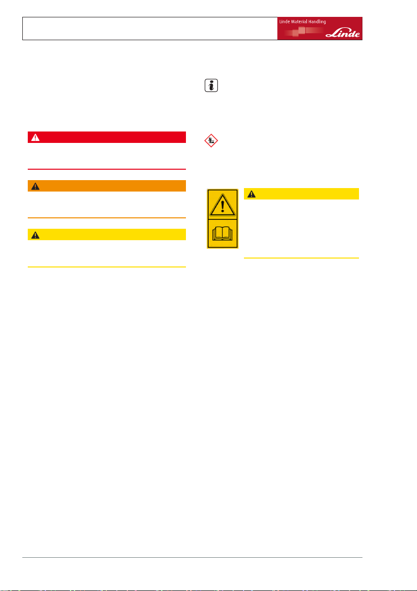
Symbols used
The terms DANGER, WARNING, CAUTION,
NOTE and ENVIRONMENT NOTE are used
in these operating instructions for notes on
particular hazards or for unusual information
that needs to be highlighted:
DANGER
Means that failure to comply can cause risk to life
and/or major damage to property.
WARNING
Means that failure to comply can cause risk of
serious injury and/or major damage to property.
CAUTION
Means that failure to comply can cause risk of
material damage or destruction.
Technical description
The forklift trucks in the 394 series allow
loading and palletising to be performed for
loadsupto4twithH40,upto4.5twithH45
and up to 5 t with H 50-500, at a load distance
of 500 mm.
Details on the exact lift-height-specific maximum loads are available in the load capacity
diagram.
The trucks are eco-friendly and their quiet
operational noise and low emission levels
benefit both the driver and the environment.
Their distinguishing features are the compact
design and small turning radius. For this
reason, the trucks are particularly well-suited
to narrow entrances and operational areas
where space is at a premium.
Engine
The drive engine is a 4-cylinder, four-stroke
diesel engine with turbocharging and state-of-
NOTE
Means that particular attention is drawn to
combinations of technical factors which may
not be evident even to a specialist.
ENVIRONMENT NOTE
The instructions listed
with as otherwise enviro
here must be complied
nmental damage may
result.
CAUTION
This label is found on the truck in
the areas where particular care and
attention are required.
You should refer to the appropriate
sectionintheseoperatinginstructions.
For your safety, additional symbols are also
used. Please heed the various symbols.
the-art pump injection technology. It powers
the truck’s hydraulic pumps and varies its
speed depending on the load. The engine is
cooled by means of a closed coolant circuit
with expansion tank.
Forced circulation lubrication with an oil pump
in the oil sump is used for engine lubrication.
The combustion air is cleaned by means of a
dry air filter with a paper insert. Diesel engines
with state-of-the-art engine technology are
used for:
• High torque
• Low fuel consumption
• Low exhaust emissions
• Low particulate emissions
• Low noise levels
Hydraulic system
The drive unit consists of a hydraulic variable
displacement pump, two hydraulic fixed
4 Operating Instructions – 394 807 10 01 EN – 07/2011
Page 17

Introduction 1
Technical description
displacement wheel motors (assembled as
a drive axle unit), as well as a hydraulic pump
(fixed displacement pump) for the working
and steering hydraulics. Drive direction and
driving speed are regulated by means of two
accelerator pedals via the hydraulic variable
displacement pump.
The hydraulic fixed displacement wheel
motors in the drive axle are supplied by the
hydraulic variable displacement pump and are
used to power the drive wheels via two side
gearboxes.
Operation
One accelerator pedal eac
and reverse travel (dual p
used to simultaneously re
variable displacement pu
speed. The hydrostatic dr
driving speed to be contin
both directions, ranging
maximum speed. The dualmeans that operation of t
safe, non-fatiguing and
The driver always has both hands free for
steering and controlling operational movements. This results in fast reversing and efficient stacking.
An optional version is also available whereby
the driving speed is regulated by an accelerator pedal (single pedal operation) and the
drive direction controlled by means of a drive
direction switch.
To control the operati
ing, lowering and tilt
ating lever (joystick
for actuation of addi
erational movements
using two or four joys
tion version).
h for forward travel
edal operation) is
gulate the hydraulic
mp and the engine
ive enables the
uously varied in
from standstill to the
pedal control
he truck is simple,
efficient.
onal movements of lift-
ing, there is only one actu-
). Another joystick is fitted
tional attachments. Op-
canalsobecontrolled
ticks (single lever opera-
Linde Load Control
The truck’s Linde Load Control (LLC) control
electronics system enables:
• Millimetre-precise and secure load handling
• Effortless finger-tip control of all lift mast
functions
• Drive and lifting functions ar
separate.
e entirely
Linde Truck Control
The truck’s Linde Truck Control control
electronics system (LTC) offers:
• Reliable control unit
• A high level of safety thank
monitoring systems
• Automatic, load-dependent control of
engine speed
• Protection from dust and dirt though use of
a fully enclosed housing.
s to multiple
Brakes
The hydrostatic drive i
brake. This means that
maintenance-free. Tw
incorporated in the wh
as the parking brake. W
switched off, the mult
meaning that the truck
function. Always appl
when parking the truck
s used as the service
the service brake is
o multi-disc brakes
eel motors are used
hen the engine is
i-disc brakes engage,
has an automatic brake
y the parking brake
.
Steering
The steering is a hydrostatic steering system,
under which the steering wheel acts on the
steering cylinder to actuate the rear wheels.
If the power applied to the steering wheel is
increased, the steering can also be operated
when the engine has been switched off.
Lift mast
The free-view lift mast enables:
• Ideal visibility
• Full load capacity up to maximum lift heights
• Enormous residual load capacity
due to slim lift mast profiles
Operating Instructions – 394 807 10 01 EN – 07/2011 5
Page 18

1 Introduction
Receiving the industrial truck
• Maintenance-free storage of the lift mast
and tilt cylinder via rubber-cushioned
linkage points
• Electric tilt angle limitation.
Electrical system
The electrical system is powered by the
three-phase alternator with 12 V DC voltage. A
12 V battery with 88 Ah is installed for starting
the engine. It is located under the driver’s seat
in the engine compartment.
Truck operation when using a shovel
When operating the truck with a shovel, stall
protection can be activated by your authorised
dealer.
In this case, extreme load
engine due to the associa
decrease leads to a sligh
the working hydraulics.
Receiving the industr
Before the industrial
it undergoes a thoro
order to guarantee t
and that it contains
specified in the orde
In order to prevent complaints from occurring
further down the line, the exact condition
of the industrial truck and the integrity of
the equipment are checked and the proper
handover/acceptance of the truck is confirmed
by the dealer.
NOTE
In trucks that lea
mast, an addition
mitation is locat
tor pedal (dual-
ve our factory without a lift
al stop screw for speed li-
ed under the reverse accelera-
pedal operation) or under the
ing of the drive
ted engine speed
t delay in executing
ial truck
truck leaves our factory,
ugh inspection process in
hat it is in perfect condition
all of the equipment
r.
For a period of extended l
engine, the joystick mus
zero position in order t
hydraulics again.
accelerator pedal (si
This must be removed
mast; see the sectio
aliftmast.
The following techn
each industrial tru
• Operating instructions for the truck
• Operating instructions for the attachment
• EC declaration of c
• Safety rules for the use of industrial trucks
• Registration document for the industrial
NOTE
oading of the
t be switched to the
o release the working
ngle-pedal operation).
after installing the lift
n entitled Driving without
ical documents belong to
ck:
(only applies to trucks delivered from the
factory with an attachment)
ompliance
(VDMA)
truck, which is issued by authorised dealers
as part of the handover.
6 Operating Instructions – 394 807 10 01 EN – 07/2011
Page 19

Legal requirements for marketing
Declaration
Linde Material Handling GmbH
Carl-von-Linde-Platz
D-63743 Aschaffenburg, Germany
We declare that the machine
Introduction 1
Legal requirements for marketing
Industrial tru
Model
complies with the most recent version of machinery directive 2006/42/EC.
Personnel a
see EC declaration of conformity
Linde Mat
ck
uthorised to compile the technical documents:
erial Handling GmbH
EC declaration of conformity
The manufacturer declares that the truck complies with the requirements of the EC machinery directive and any other EC directives, if
applicable, that are valid at the time of marketing. This is confirmed by the EC declaration
of conformity and by the CE labelling on the
nameplate.
The EC declaration of conformity document
is delivered with the truck. The declaration
according to these operating instructions
according to these operating instructions
shown explains the conformity with the requirements of the EC machinery directive.
An independent structural change or addition
to the truck can compromise safety, thus
invalidating the EC declaration of conformity.
The EC declaration of conformity must be
carefully stored and made available to the
responsible authorities if applicable. It must
also be handed over to the new owner if the
truck is sold on.
Operating Instructions – 394 807 10 01 EN – 07/2011 7
Page 20

1 Introduction
Legal requirements for marketing
8 Operating Instructions – 394 807 10 01 EN – 07/2011
Page 21

2
Safety
Page 22
2 Safety
Safety guidelines
Safety guidelines
It is essential that operating personnel and
repair personnel observe the" rules for the
proper use of industrial trucks" enclosed with
these operating instructions.
Examples of those listed are:
• Operating industrial trucks
• Driving licence
• Driveways and working areas
• Rights, duties and rules of behaviour for the
driver
• Special operating areas
• Information regarding setting off, driving
and braking
• Information for maintenance and repair
• Regular tests
• Disposal of greases, oils and batteries
The operating company or the person it has
commissioned must ensure that the driver
understands all safety information and that
all guidelines and safety regulations are
observed.
During training, the driver must familiarise
themselves with the following:
• The operating conditio
areas
• The specific technical characteristics of the
industrial truck
• The operation of attachments
Practise driving, con
ations with an unloade
completely mastered.
industrial truck be us
Safety information
DANGER
The industrial truck must not be used by unauthorised persons.
Only trained persons and those authorised for
operation may have access to the industrial truck.
ns of the working
trol and steering oper-
d truck until they are
Only then can a loaded
ed for practice.
DANGER
In operating areas with magnetic fields that have a
magnetic flux density greater than 5 mT, unintentional truck and lift mast movementscannot be entirely
excluded under unfavourable circumstances.
For magnetic fields with magnetic flux densities
greater than 5 mT, components developed especially for this purpose must be used.
Contact your authorised dealer.
DANGER
Safety systems (e.g. the seat switch) are there for
safety.
Safety systems must never be disabled, regardless
of the kind.
DANGER
Any additional bores or welding to the overhead
guard will compromise its rigidity.
It is therefore strictly prohibited to drill holes in the
overhead guard or to weld to it.
CAUTION
Welding operations on other parts of the vehicle
can cause damage to the electronics.
Therefore, before performing any welding, always
disconnect the battery and all connections to the
electronic control units.
CAUTION
Different functions are supported by gas springs.
Gas springs are under a high internal pressure of
up to 300 bar.
They must only be removed when not under compression and must not be opened without instructions. Any kind of damage, lateral forces, buckling,
temperatures in excess of 80° C and heavy contamination must be avoided under all circumstances.
Damaged or defective gas springs must be replaced immediately.
Contact your authorised dealer.
10 Operating Instructions – 394 807 10 01 EN – 07/2011
Page 23

Safety 2
Residual risks
WARNING
In trucks with an accumulator, serious injuries can
occur if the accumulator is not properly handled.
Before starting work on the accumulator it must be
depressurised.
Contact your authorised dealer.
WARNING
Depending on the duration of use and
operating time, components carrying
exhaust gases and exhaust air may
become hot.
Protective equipment must therefore
be worn.
WARNING
Thetruckworkingareamustbesufficientlylit.
If it is insufficiently lit, working spotlights must be
installed to ensure that the driver can see properly.
Residual risks
Despite careful work and compliance with
all applicable standards and regulations, the
possibility of other dangers when using the
industrial truck cannot be entirely excluded.
The industrial truck and its possible attachments comply with current safety regulations.
Nevertheless, even when the truck is used for
its proper purpose and all instructions are followed, some residual risk cannot be excluded.
Even beyond the narrow danger areas of the
industrial truck itself, a residual risk cannot
be excluded. Persons in the area around the
industrial truck must exercise a heightened
degree of awareness, so that they can react
immediately in the event of any malfunction,
incident or breakdown.
CAUTION
Various pieces of special equipment are connected
to the special "speed reduction" function. This is
simply an assistance function, on which the driver
must not solely rely during operation.
The driver is always responsible for safe operation.
CAUTION
If drivers have active medical equipment, e. g. pace
makers or hearing aids, these may be impaired.
Check with a doctor or the medical equipment
manufacturer whether the equipment is sufficiently
protected against electromagnetic interference.
NOTE
If your truck is equipped with a fire extinguisher, make sure that you familiarise yourself
with it in case of an emergency. Handling information is provided on the fire extinguisher.
DANGER
Persons in the vicinity of the industrial truck must
be instructed with regard to the dangers that arise
through use of the truck.
These operating instructions also contain additional
safety regulations.
Residual dangers can include:
• Escape of consumables due to leakages or
the rupture of lines, hoses or containers,
• Risk of accident when driving over difficult
ground such as gradients, smooth or
irregular surfaces, or with poor visibility,
• Risk of falling, tripping, slipping etc. during
movement of the industrial truck, especially
in the wet, with leaking consumables or on
icy surfaces,
• Risk of fire and explosion due to the battery
and electrical voltages,
• Human error,
• Disregarding the safety regulations,
• Risk caused by unrepaired damage,
Operating Instructions – 394 807 10 01 EN – 07/2011 11
Page 24
2 Safety
Handling consumables
• Risk caused by insufficient maintenance or
testing,
• Risk caused by using the wrong consumables.
Stability
Stability is guaranteed if your industrial truck is
used according to its intended purpose.
Stability will not be guaranteed in the event of:
• cornering at excessive sp
• moving with the load raised,
• moving with a load that is protruding to the
side (e.g. sideshift),
eeds,
In the case of tip-over
• turning and driving diagonally across
descents or ascents,
• driving on descents or asc
on the downhill side,
• loads that are too wide,
• driving with a swinging load,
• ramp edges or steps.
ents with the load
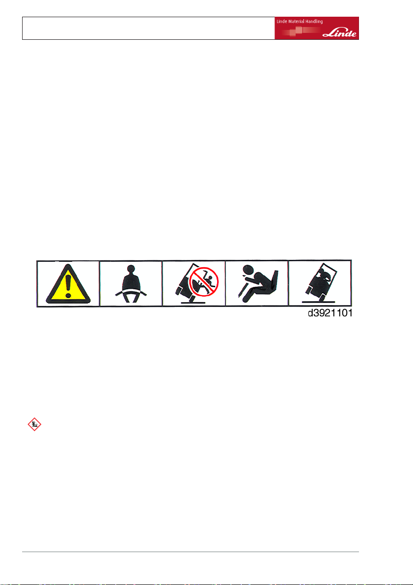
• Stay buckled up
•Don’tjump
• Hold on tight
•Bracefeet
• Lean away
Handling con
ENVIRONMENT NOTE
Consumables must be handled properly
and in accordance with the manufacturer’s
instructions.
• Consumables should only be stored in
containers complying with applicable
regulations and at the locations stipulated.
• Do not brin
contact wi
• When topping up consumables, use only
clean containers.
12 Operating Instructions – 394 807 10 01 EN – 07/2011
sumables
g flammable consumables into
th hot objects or a naked flame.
The stability of your industrial truck is ensured
if used properly and as intended. Should the
industrial truck tip over during an unapproved
application or due to incorrect operation,
always follow the instructions depicted above.
• Observe the manufacturer’s instructions
relating to safety and disposal.
• Avoid spill
• Remove any spilled fluid immediately with a
suitable binder and dispose of it according
to applicable regulations.
• Old and contaminated operating materials
should be disposed of according to the
regulations.
• Comply wit
• Before performing greasing, filter changes
or any work on the hydraulic system,
ing.
h the statutory provisions.
Page 25

Safety 2
Regulations
carefully clean the area around the part
involved.
• Dispose of used spare parts in an environmentally friendly manner.
WARNING
The penetration of pressurised hydraulic fluid into
the skin, e.g. due to leakage, is hazardous. If an
injury of this type occurs, always consult a doctor.
Protective equipment must be worn.
Competent person
A competent person is a specialist in the field
of industrial trucks who has:
• Successfully completed training, as at least
a service engineer for industrial trucks
• Many years of professional experience with
industrial trucks
• Knowledge of the accident prevention
regulations
• Knowledge of the relevant national technical regulations
Regulations
Periodic safety inspection
Periodic safety inspections are required in
order to maintain the function and security of
the industrial truck.
Comply with the national regulations for your
country.
In Europe, the national laws are based
on the directives 95/63/EC, 99/92/EC and
2001/45/EC. These stipulate that periodic
safety inspections of the industrial truck must
be carried out by competent personnel, in order to ensure proper condition.
WARNING
The improper handling of coolant and coolant additives presents a risk to health and the environment.
Observe the manufacturer’s instructions without
fail.
The competent person is able to assess the
condition of industrial trucks in terms of health
and safety.
Operating Instructions – 394 807 10 01 EN – 07/2011 13
Page 26
2 Safety
Instructions for fitting attachments
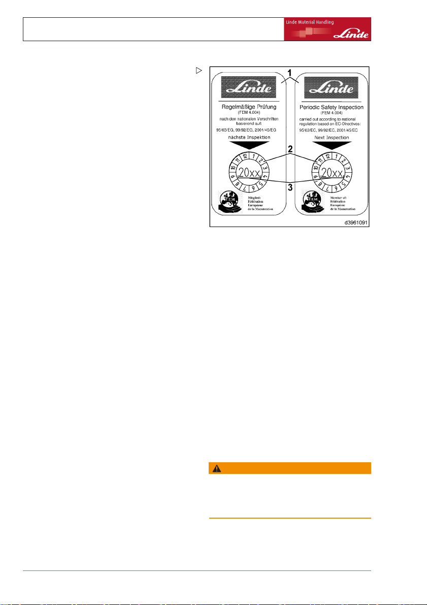
There is a recommendation setting out the
scope of the periodic safety inspection —FEM
4.004 of the European Industrial Truck Association— which defines a test log to document
the current safety inspection and an inspection
sticker for the next safety inspection. The next
safety inspection date is shown by the year
number (3) on an adhesive label (2), which
changes colour every year and is found on a
label (1).
The scope of the safety inspection is added
by the manufacturer in accordance with
the specific truck type. Please ask your
authorised dealer to carry out this work.
Diesel engine emissions
Diesel engine emissions i
hazardous materials. The
allowed to infiltrate the a
If trucks with diesel engines are used in fully
or partially enclosed spaces, this must first be
reported to the relevant occupational health
and safety authorities. Operating instructions
must be displayed in the working areas.
The national regulations must be observed
without fail.
nclude carcinogenic
se should not be
ir in workplaces.
Checking the particle filter system
Particle filter syste
and tested every 6 mon
person. The test resu
enclosed with the rep
national regulation
Instructions for fi
To depressurise th
fitting an attachme
for the auxiliary h
using an accumulat
depressurised
See the section entitled "Depressurisation".
14 Operating Instructions – 394 807 10 01 EN – 07/2011
ms must be maintained
thsbyacompetent
lts must be recorded and
ort book. Observe the
s for your country.
tting attachments
e oil in the lines before
nt, the hydraulic system
ydraulics can be connected
or (Special equipment)
WARNING
Improper handling of the accumulator may lead to
serious injuries.
Before starting work on the accumulator, it must be
depressurised. Contact your authorised dealer.
Page 27
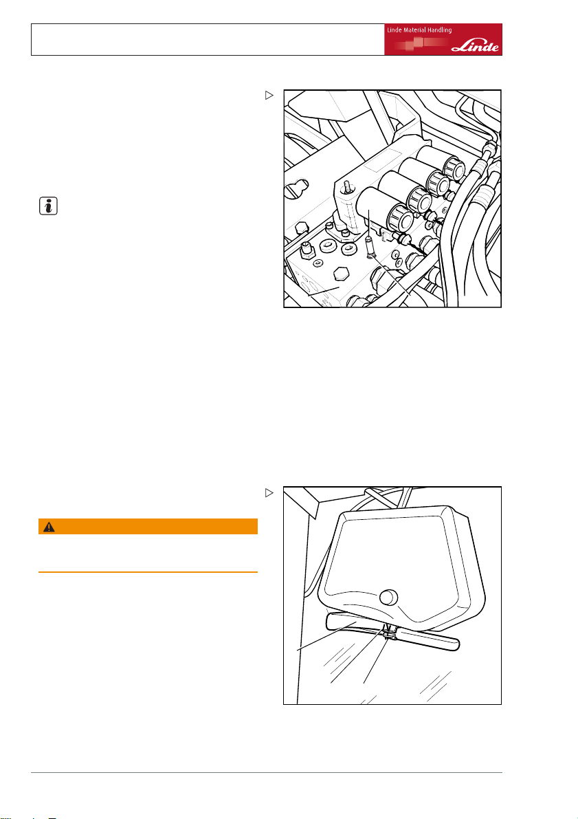
Fork carriage emergency lowering
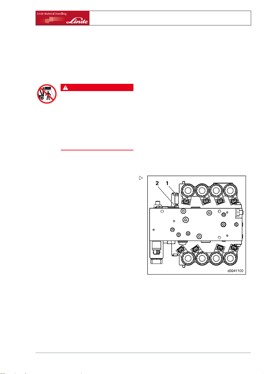
If there is a malfunction, the fork carriage can
be lowered manually.
¾ Remove floormat.
DANGER
Risk of accident or danger to life
when lowering the fork carriage with
fork arms.
People are not allowed to stand in the
vicinity of the fork arms when they are
being lowered.
During lowering, leave the socket
wrench on the threaded stud (1) on
the valve block (3) to enable lowering
to be interrupted at any time.
¾ Insert the 8 mm WAF socket wrench
through the opening in the bottom plate.
¾ Using the socket wrench slowly rotate
the threaded stud (1) approx. 3 turns
anti-clockwise until the fork carriage has
been completely lowered.
¾ Open the bonnet.
¾ Open the bottom plate and secure it in
place.
¾ Undo the self-locking nut (2) about 2 turns.
Safety 2
Fork carriage emergency lowering
Operating Instructions – 394 807 10 01 EN – 07/2011 15
Page 28
2 Safety
Emergency exit with attached rear window
¾ Screw the threaded stud (1) back in clock-
wise. Otherwise it will not be possible to lift
the fork carriage using the joystick.
Tightening torque 10 Nm.
¾ Retighten the self locking nut
Tightening torque 9.5 Nm
NOTE
After emergency lowering
med three times, a new thre
locking nut must be used.
¾ Close the bottom plate and bonnet.
¾ Insert the floormat.
(2).
has been perfor-
aded stud with self
1
3
2
d3941386
Emergency exit wi
th attached
rear window
If a truck with a
window breaks d
driver may poss
at the side. In t
driver can exit
For this purpos
broken with an e
¾ Bend open split pin (1) from the support
mounting (2) under the rear wiper motor.
WARNING
Glass splinters may cause injuries.
Remove glass splinters carefully.
¾ Take the emergency hammer (3) out of the
support mounting and carefully break the
rear window.
¾ Climb out carefully.
n attached front and rear
own in a narrow aisle, the
ibly be unable to exit the truck
he event of acute danger, the
the truck via the rear window.
e, the rear window must be
mergency hammer.
3
2
1
t3921371
16 Operating Instructions – 394 807 10 01 EN – 07/2011
Page 29

3
Overview
Page 30
3 Overview
Identification plates
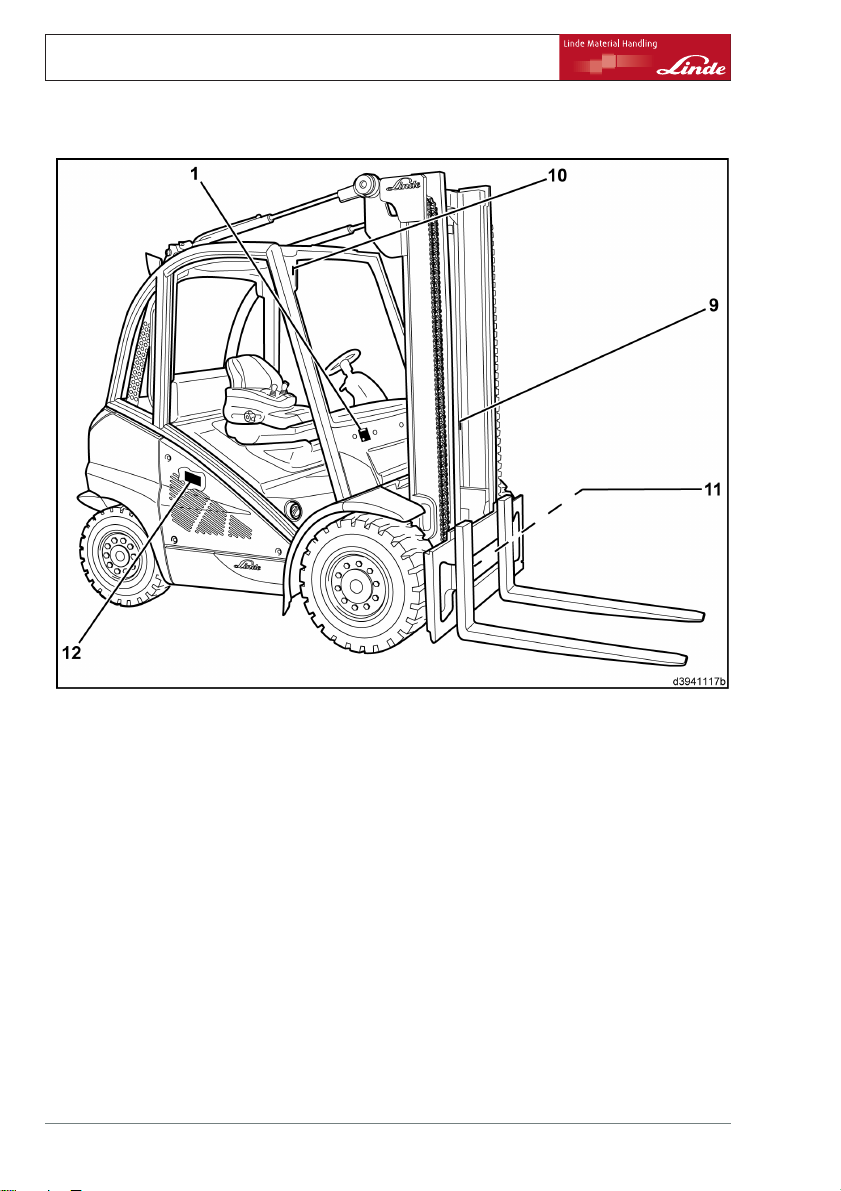
Identification plates
1 Nameplate
9
Lift mast n
10
Serial number (stamped into the
front right of the junction plate on
the overhead guard)
11
Drive axle identification plate
12
Engine
18 Operating Instructions – 394 807 10 01 EN – 07/2011
umber (adhesive label)
identification plate
Page 31

Nameplate
1 Nameplate
2
Manufacturer
3
Type/chassis number/year of
manufacture
4 Tare weight
5
Placeholder for "data-matrix code"
6
CE mark
7
Rated driving power
8 Rated load capacity
NOTE
The CE mark confirms compliance with the EC
machinery directive and with all regulations
applicable to the truck.
Steering axle identification plate
13
Steering axle identification plate
Overview 3
Identification plates
Operating Instructions – 394 807 10 01 EN – 07/2011 19
Page 32

3 Overview
General view
General view
1Liftmast
2 Lift cylinder
3 Composite instrument
4 Tilt cylinders
5 Switch panel for toggle switch (special
equipment)
6 Joystick
7 Steering wheel/hydrostatic power steering
8 Operator’s seat
9 Electrical system cover
10 Fuses (behind the electrical system cover)
11 Counterweight
12 Steering axle
20 Operating Instructions – 394 807 10 01 EN – 07/2011
13 Access cover
14 Chassis and overhead guard
15 Bonnet
16 Step for mounting and dismounting
17 Fuses (in the engine compartment)
18 Left drive unit
19 Fork carriage
20 Fork quick-releases
21 Forks
22 Fork stops
23 Handhold for entering and exiting the truck
(special equipment)
24 Lift mast chain
Page 33

Operating devices
Overview 3
Operating devices
1 Indicator light for turn indicator and hazard
warning system (green) (special equipment)
2 Clamping screw for adjusting the steering
column
3 Multifunction lever for wiper/washer system
and turn indicator (special equipment)
4 Steering wheel / hydrostatic steering
5 Parking brake lever
6 Startingswitchwithswitchkey
7 Compartment
8 Joystick for working hydraulics
9 Joystick for auxiliary hydraulics (attach-
ments) (special equipment)
Operating Instructions – 394 807 10 01 EN – 07/2011 21
10 Symbol label for auxiliary hydraulics (attach-
ments) (special equipment)
11 Symbol label for working hydraulics
12 Signal button
13 Armrest on driver’s seat
14 Driver’s seat
15 Forward travel accelerator pedal
16 Stop pedal
17 Reverse travel accelerator pedal
18 "Guaranteed sound power level" label
19 "Truck configuration" sign (for description,
see "truck configuration sign")
Page 34

3 Overview
Display unit
Display unit
22 Operating Instructions – 394 807 10 01 EN – 07/2011
Page 35

Overview 3
Display unit
1 Display unit
2 Hydraulic oil temperature indicator
3 Charging indicator
4 Engine oil pressure indicator / engine oil
level indicator (special equipment)
5 Electrical controller fault
6 Engine coolant temperature indicator
7 Joystick display electronically unlocked
8 Particle filter warning
9 Symbol without function
10 Water in the fuel filter (special equipment)
11 Hydraulic oil microfilter indicator (special
equipment)
12 Level display for diesel tank, LPG tank /
replacement cylinders or CNG tank
13 Symbol for "Particle filter"
14 Symbol without function
15 Symbol for "Service interval exceeded"
16 Operating hours symbol
17 Operating hours display
18 Symbol without function
19 Symbol for "Clock display (am/pm)"
20 Symbol without function
21 Function key
22 Reset button
23 Time display
24 "Do not start the engine" symbol
25 Symbol for "Parking brake applied"
26 Symbol for "Operating hours until the next
service" (shown for only 5 sec in the display
(17))
27 Symbol for "Seat belt not fastened" (special
equipment)
28 Text field
29 "Lift mast positioning" symbol active (special
equipment)
30 Display
31 Air filter vacuum indicator
32 Coolant level indicator
33 Preheating indicator (function only available
on diesel trucks)
34 Gas system error light (function only avail-
able on LPG trucks)
35 Engine malfunction warning light
The display unit (1) is mounted to the top right on the overhead guard. It is positioned within the
driver’s field of vision and provides centralised information about all functions of the truck. After
the key switch has been switched on, a self-test of the display unit is then performed. During the
self-test, all indicator lights and the displays are activated.
Display element
(2) Hydraulic oil temperature
indicator
(red)
Function
- Lights up if the maximum
permissible temperature is
reached. A buzzer also sounds
if the temperature limit is
exceeded.
When the "Engine protection"*
function is activated):
Possible malfunctions
Remedy
Insufficient oil in the hydraulic
circuit
Incorrect oil used
Oil filter clogged
il cooler contaminated
O
- Truck moves at creep speed
(approx. 2 km/h)
Display in the text field (28):
- Error code
X205
Switch off the buzzer with the
reset button (22)
Operating Instructions – 394 807 10 01 EN – 07/2011 23
Page 36

3 Overview
Display unit
Display element
(3) Charging indicator
(red)
(4) Engine oil pressure
indicator/engine oil level
indicator
(red)
(5) Electrical controller fault
(red)
(6) Engine coolant temperature indicator
(red)
(7)Joystick display electronically unlocked
(green)
Function
- Lights up if there are
generator malfunctions.
- Lights up and buzzer sounds
when the oil pressure is too
low.
- If the text field (28) also
shows
Oil with a double
arrow pointing downwards,
the engine oil level is too low.
(special equipment)
When the "Engine protection"*
function is activated):
- Truck moves at creep speed
(approx. 2 km/h)
Display in the text field (28):
- Error code
pressure is too low
- Error code
with double arrow pointing
down, if the oil level is too low.
- Lights up when an electrical
fault is present.
Error code is displayed in the
text field (28).
- Lights up if the maximum
permissible temperature is
reached. A buzzer also sounds
if the temperature limit is
exceeded.
When the "Engine protection"*
function is activated):
- Truck moves at creep speed
(approx. 2 km/h)
Display in the text field (28):
- Error code
- Lights up when the "Joystick
unlocked" function is activated.
X202 if the oil
X201 and Oil
X204
Possible malfunctions
Remedy
V-ribbed belt split or v-ribbed
belt tension too slack
V-ribbed belt tensioner faulty
Cable faulty
Alternator faulty
Charging controller or cut-out
relay faulty
Short circuit at output D+ of the
display unit
Insufficient oil i
Engine too hot
Incorrect oil used
Internal leakage in the
lubricating oil circuit
Top up with engine oil
Switch off the buzzer with the
reset button (22)
Fan motor fa
Thermal sw
Water co
Leakage in the cooling circuit
Coolant level too low
Switch off the buzzer with the
reset button (22)
n the crankcase
ulty
itch faulty
oler contaminated
24 Operating Instructions – 394 807 10 01 EN – 07/2011
Page 37

Overview 3
Display unit
Display element
(8) Particle filter error
(red)
(9) Symbol without func
(10) Water in the fuel filter
(yellow)
(special equipment)
(11) Hydraulic oil microfilter
indicator
(yellow)
(special equipment)
(12) Level display for diesel
tank, LPG tank/replacement
cylinders or CNG tank
(green or red depending on
the fuel level)
(13) Symbol for "Particle
filter"
(14) Symbol without function
(15)"Service interval
exceeded" symbol
(16) Operating hours symbol
tion
Function
- Lights up when the particle
filtercontrolsystemis
activated, if the load period
of the particle filter exceeds
8.5 h
- Additionally, a buzzer sounds
and an error code appears in
the text field (28) in the event of
an error in the particle filter
control system. The truck
moves only at creep speed
(approx. 2 km/h).
- Lights up if water has
collected in the fuel filter
- Additionally, a buzzer sounds
if the warning light is activated
for more than 5 seconds
- Lights up if the pressure filters
require maintenance work.
Shows the current fuel
level in the diesel tank, the
current level in the LPG
tank/replacement cylinders
or the current level in the CNG
tank.
- Lights up if the particle filter
control system is active.
If the number of operating
hours until the next service
is less than or equal to
zero, the symbol flashes for
10 seconds every time the
truck is started, and then lights
up continuously.
Flashes when operating hours
are being counted (only when
the ignition is on and the engine
speed exceeds 300 rpm).
Possible malfunctions
Remedy
Regenerate the particle filter
immediately
Error in the particle filter control
system
Drain water from the fuel filter
Switch off the buzzer with the
reset button (22)
Microfilter clogged, change it
The display can only be reset
using the diagnostic program.
Operating Instructions – 394 807 10 01 EN – 07/2011 25
Page 38

3 Overview
Display unit
Display element
(17) Operating hours display
(18) Symbol without funct
(19) Clock display (am/pm)
(20) Symbol without function
(21) Function key
(22) Reset button
(23) Time display
(24)"Do not start the engine"
symbol
(25)"Parking brake" symbol
(26)"Operating hours until the
next service" symbol
(27) Symbol for "Seat belt not
fastened"
(special equipment)
ion
Function
Indicates the operating hours
of the truck. This display
is evidence of the truck’s
operating time and of the
inspection and maintenance
work to be performed.
For 12-hour format:
am = morning
pm = afternoon
- Adjusting the time
- Scrolling through error
messages
- Adjusting the time
- Scrolling through erro
messages
- Turning off the warnin
24-hour clock displa
Adjustable using the
(22) push buttons.
- Lights up when the
has stalled. (A blo
repeat starting is
engine cannot be st
- Lights up if the parking brake
is activated
After the ignition has been
switched on, display field (17)
shows the operating hours
until the next service (counting
backwards).
Symbol (26) lights up. After
5 seconds, symbol (26) goes
out and display (17) switches
automatically to the truck’s
operating hours; the operating
hours symbol (16) flashes.
- Lights up if seat belt was not
fastened
r
g sound
y.
(21) and
engine
ck against
active and the
arted).
Possible malfunctions
Remedy
If a faulty display unit is
replaced, the operating hours
up to that point must be
recorded. Affix the data on an
embossed strip near the display
unit. There is also the option of
updating the new display unit at
a later time.
The diagnostic program can be
used to reset the display to a
12-hour clock.
The diagnostic program can be
used to reset the display to a
12-hour clock.
Always leave the ignition
switched on until the symbol
goes out.
Then repeat the start attempt.
Fasten the seat belt
26 Operating Instructions – 394 807 10 01 EN – 07/2011
Page 39

Overview 3
Display unit
Display element
Text field (28)
(29)"Lift mast positioning"
symbol
(special equipment)
Display (30)
(31) Air filter vacuum
indicator
(yellow)
(32) Coolant level indicator
(yellow)
(33) Glow plug indicator
(yellow)
(34) Gas system error light
(red)
(35) Engine malfunction
warning light
(yellow)
Function
Serves as display field for error
code display and charge status
display for the particle filter (in
line 1).
- Lights up when the "Lift
mast positioning" function is
activated
Serves as a text display and
symbol display
- Lights up when the air filter is
excessively clogged.
- Lights up when the coolant
level is below the minimum
When the "Engine protection"*
function is activated):
- Truck moves at creep speed
(approx. 2 km/h)
Display in the text field (28):
- Error code
Function only available on
diesel trucks:
- Lights up whilst the glow plugs
are preheating, then goes out
- Flashes when a malfunction
exists in the engine or in the
engine control unit.
Function only available on LPG
trucks:
- Lights up if an error is detected
in the gas system.
- Lights up if an error is detected
by the engine control unit.
X203
Possible malfunctions
Remedy
Charge status display:
- 0 symbols blacked out =>
particle filter empty
- 11 symbols blacked out =>
particle filter full
Air filter clogged, change it.
Top up the coolant.
Identify the error using the
diagnostic program.
Identify the error using the
diagnostic program.
Identify the error using the
diagnostic program.
*) The "Engine protection" function (special equipment) can be disabled using the diagnostic
program. Contact your authorised dealer.
Operating Instructions – 394 807 10 01 EN – 07/2011 27
Page 40

3 Overview
Switch panel
Switch panel
The switch panel is mounted at the top right of the
overhead guard.
1 Interior lighting
2 Standard or higher lighting
3 Working spotlight position 1/2
4 Working spotlight position 3/4 or working
spotlight position 5/6
5 Working spotlight position 7/8
6 Front windscreen wiper and rear window
wiper — continuous operation on/off (inter-
val depends on the drive direction and the
washer system is always activated)
7 Roof panel wiper - intermittent mode or
continuous operation on/off (washer system
is activated)
8 Rear window heating
9 Hazard warning light
10 Rotating beacon or flashing beacon
11 Particle filter starting switch
12 Particle filter stop/reset switch
13 Changing particle filter system error light
NOTE
The configuration of the switch panel and
arrangement of individual switches may vary,
depending on the version. Observe the switch
symbols.
28 Operating Instructions – 394 807 10 01 EN – 07/2011
Page 41

4
Operation
Page 42

4 Operation
Running-in instructions
Service plan before initial commissioning
Engine
Fill up with fuel
Check the engine oil level
Checking the coolant level
Regenerate the particle filter
Chassis frame
Tighten wheel fastenings
Check the tyre pressure
Checking the brake system
Check steering system.
Electrics / Electronics
Battery: check condition, acid level and acid density
Hydraulics
Hydraulic system: Check the oil level.
Check lifting system and attachments.
Carried
out
9
8
Running-in instructions
The truck can be operated quickly immediately. Avoid high sustained loads on the working hydraulics and on the travel drive in the
first 50 hours. The wheel fasteners must be
tightened before the commissioning and after
each wheel change. Then after 100 service
30 Operating Instructions – 394 807 10 01 EN – 07/2011
hours minimum. Tighten opposite wheel fasteners to a torque of
Front: 425 Nm
Rear: 640 Nm
Page 43

Pre-shift-checks
Pre-shift-checks
Engine
Check the fuel level
Check the engine oil level
Checking the coolant level
Chassis frame
Check the tyre pressure
Check the condition of the antistatic belt (only when using tyres that are not antistatic)
Hydraulics
Hydraulic system: Check the oil level.
Operation 4
Carried
out
8
9
Operating Instructions – 394 807 10 01 EN – 07/2011 31
Page 44

4 Operation
Standard equipment
Standard equipment
Entering and exiting the truck
WARNING
Entering and exiting the truck can result in injuries
to the feet or back.
Always face the truck when you enter or exit the
truck.
NOTE
Do not use the steering wheel or the actuating
levers as an aid to get in or out.
¾ Use handle (1) (special equipment) or
longitudinal member (2) and step (3).
Adjusting the standard driver’s seat
and comfort driver’s seat
WARNING
If the seat is not adjusted correctly, this may cause
injury to the driver’s back. The adjustment controls
for the driver’s seat should not be used during
operation.
Before starting the truck and whenever changing
drivers, adjust the seat to correspond to the driver’s
weight and make sure that the settings have all
engaged properly. Do not place any objects in the
driver’s rotation range.
32 Operating Instructions – 394 807 10 01 EN – 07/2011
Page 45

NOTE
Sitting for long periods of tim
pressure on the spine. Try to co
this by performing regular sim
e puts a lot of
mpensate for
ple gymnastic
movements.
Longitudinal adjustment
¾ Pull lever (1) upwards.
¾ Move the driver’s seat backwards or for-
wards on the runners to find the most comfortable position for the driver in relation to
the steering wheel and the accelerator pedals.
¾ Allow lever (1) to snap in
to place.
Operation 4
Standard equipment
Adjusting the seat back
¾ Push lever (2) upwards and hold in place.
¾ Move the seat backrest forwards or back-
wards until a comfortable seating position
for the driver is found.
¾ Release lever (2).
Setting the driver’s
NOTE
rest
weight
The individual driver’s weight must be set
when the driver’s seat is under load.
¾ Check the weight setting in the inspection
window (4).
The correct driver’s weight has been set
when the arrow is in the centre position in
the inspection window (4).
Adjust the driver’s weight as necessary.
¾ Pull out the lever (3).
Move the lever to set the driver’s weight for the
suspension.
¾ Move the lever (3) upwards for a heavier
weight.
¾ Move the lever (3) downwards for a lighter
weight.
Operating Instructions – 394 807 10 01 EN – 07/2011 33
Page 46

4 Operation
Standard equipment
Adjusting the lumbar support (only with a
comfort driver’s seat)
NOTE
The lumbar support enables optimum configuration of the seat back contour to the driver’s
body.
¾ Turn knob (5) to the left or right.
The extent to which the lower and upper
areas of the backrest are curved is adjusted
individually.
Adjusting the height-adjustable
comfort driver’s seat
WARNING
If the seat is not adjusted correctly, this may cause
injury to the driver’s back. The adjustment controls
for the driver’s seat should not be used during
operation.
Before starting the truck and whenever changing
drivers, adjust the seat to correspond to the driver’s
weight and make sure that the settings have all
engaged properly. Do not place any objects in the
driver’s rotation range.
NOTE
Sitting for long periods of time puts a lot of
pressure on the spine. Try to compensate for
this by performing regular simple gymnastic
movements.
34 Operating Instructions – 394 807 10 01 EN – 07/2011
Page 47

Longitudinal adjustment
¾ Pull lever (1) upwards.
¾ Move the driver’s seat backwar
wards on the runners to find the m
fortable position for the driv
the steering wheel and the acce
als.
¾ Allow lever (1) to snap into place.
ds or for-
ost com-
er in relation to
lerator ped-
Adjusting the seat backrest
¾ Push lever (2) upwards and hold in place.
¾ Move the seat backrest forw
wards until a comfortabl
for the driver is found.
¾ Release lever (2).
ards or back-
e seating position
Setting the driver’s weight
NOTE
The individual driver’s weight must be set
when the driver’s seat is under load.
¾ Check the weight setting in the inspection
window (4).
The correct driver’s weight has been set
when the arrow is in the centre position in
the inspection window (4).
Adjust the driver’s weight as necessary.
¾ Pulling the lever (3) upwards signifies a
higher weight.
¾ Pushing the lever (3) downwards signifies a
lower weight.
Operation 4
Standard equipment
Operating Instructions – 394 807 10 01 EN – 07/2011 35
Page 48

4 Operation
Standard equipment
Adjusting the lumbar support
NOTE
The lumbar support enables optimum configuration of the seat back contour to the driver’s
body.
¾ Turn knob (5) to the left or right.
The extent to which the lower and upper
areas of the backrest are curved is adjusted
individually.
Adjusting the seat height
Adjust the seat height as required.
¾ Pulling the lever (
seat moves upward
¾ Pushing the lever (3) downwards means
that the seat moves downwards.
3) upwards means that the
s.
NOTE
After making the adjustment, the arrow in the
inspection window (4) may deviate somewhat
from the centre position.
Adjusting the luxury driver’s seat
WARNING
If the seat is not adjusted correctly, this may cause
injury to the driver’s back. The adjustment controls
for the driver’s seat should not be used during
operation.
Before starting the truck and whenever changing
drivers, adjust the seat to correspond to the driver’s
weight and make sure that the settings have all
engaged properly. Do not place any objects in the
driver’s rotation range.
36 Operating Instructions – 394 807 10 01 EN – 07/2011
Page 49

NOTE
Sitting for long periods of tim
pressure on the spine. Try to co
this by performing regular sim
e puts a lot of
mpensate for
ple gymnastic
movements.
Longitudinal adjustment
¾ Pull lever (1) upwards.
¾ Move the driver’s seat backwards or for-
wards on the runners to find the most comfortable position for the driver in relation to
the steering wheel and the accelerator pedals.
¾ Allow lever (1) to snap in
to place.
Operation 4
Standard equipment
Adjusting the seat back
¾ Push lever (2) upwards and hold in place.
¾ Move the seat backrest forwards or back-
wards until a comfortable seating position
for the driver is found.
¾ Release lever (2).
Setting the driver’s
The correct driver’s weight will be set automatically if the ignition is switched on and the
driver’s seat is occupied.
rest
weight
Operating Instructions – 394 807 10 01 EN – 07/2011 37
Page 50

4 Operation
Standard equipment
Adjusting the seat angle
¾ Pull lever (3) upwards.
The seat surface is moved to the
position by applying pressure
surface or removing pressure f
Adjusting the seat depth
¾ Pull lever (4) upwards.
The seat surface can be moved to the desired
position by sliding the seat surface forwards or
backwards.
Adjusting the backrest extension
¾ Push backrest extensio
for individual adjustm
ent.
desired
to the seat
rom it.
n (5) in or pull it out
Adjusting the lumbar su
NOTE
pport
The lumbar support enables optimum configuration of the seat back contour to the driver’s
body.
¾ Press button (6).
The extent to which the upper area of the
backrest is curved is adjusted individually.
¾ Press button (7).
The extent to which the lower area of the
backrest is curved is adjusted individually.
Activating the seat heater (luxury driver’s
seat)
¾ Push the switch (8) downwards to activate
the seat heater.
¾ Push the switch (8) upwards to deactivate
the seat heater.
NOTE
The maximum temperature is predefined.
38 Operating Instructions – 394 807 10 01 EN – 07/2011
Page 51

Adjusting the luxury active driver’s seat
The luxury active driver’s seat is operated in
exactly the same way as the luxury driver’s
seat. Only the activation of the seat heater is
different.
Activating the seat heater (luxury active
driver’s seat)
¾ Push the switch (9) upwards
seat heater.
¾ Push the switch (9) to the centre position to
deactivate the seat heater.
to activate the
Activating the seat air-conditioning
(luxury active seat)
¾ Push the switch (9) downwards to activate
the seat air-conditioning.
¾ Push the switch (9) to th
deactivate the seat air
NOTE
e centre position to
conditioning.
The maximum temperature is predefined.
Operation 4
Standard equipment
Adjusting the armr
¾ Sit on the driver’s
screw (1).
¾ Move armrest (2) upwards/downwards
and forwards/backwards until the arm is
comfortably supported and the joysticks (3)
can be easily reached.
¾ Tighten clamping screw (1).
Operating Instructions – 394 807 10 01 EN – 07/2011 39
est
seat and release clamping
Page 52

4 Operation
Standard equipment
Adjusting the steering column
DANGER
Safe driving is not guaranteed with the clamping
screw open.
Only adjust the steering column when the vehicle is
stationary.
Angle adjustment
¾ Undo the clamping screw (2) anticlockwise.
¾ Move the steering wheel (1) into the re-
quired position.
¾ Tighten the clamping screw (2) clockwise.
Height adjustment (special equipment)
¾ Undo the clamping screw (2) anticlockwise.
¾ Move the steering wheel (1) into the re-
quired position by pulling it upwards or
pushing it downwards.
¾ Tighten the clamping screw (2) clockwise.
Setting the clock
NOTE
The time is displayed in 24-hour format. It is
possible to change to 12-hour format using
the diagnostic device. Please contact your
authorised dealer.
40 Operating Instructions – 394 807 10 01 EN – 07/2011
Page 53

¾ Press both push buttons (2) and (3) simulta-
neously for 3 seconds.
The hour readout in the time display (1)blinks.
NOTE
The hours or minutes can be adjusted gradually by pressing push button (2) or quickly by
holding down the push button.
¾ Depress button (2) to set the hours.
¾ Depress button (3) to confi
rm the hour
setting.
Now the minute readout blinks.
¾ Depress button (2) to set the minutes
¾ Depress button (3) to co
nfirm the setting of
the minutes.
Seat belt
DANGER
There is a risk to life if the driver
leaves the vehicle in an uncontrolled
manner.
For this reason, the seat belt must
always be worn when operating the
truck! The seat belt should only be
worn by one person.
Operation 4
Standard equipment
WARNING
The seat belt must function perfectly.
For this reason, the belt should not become twisted, trapped or tangled. The belt buckle and belt
retractor should be protected from foreign bodies,
damage and dirt.
NOTE
Driver’s cabs with fixed closed doors or
bracket doors meet the safety requirements
for driver restraint systems. The seat belt may
also be used. It must, however, be fastened
when driving with doors that are open or have
been removed. PVC doors do not constitute
a driver restraint system. For trucks with the
Operating Instructions – 394 807 10 01 EN – 07/2011 41
Page 54

4 Operation
Standard equipment
"speed reduction" special function, the seat
belt must be worn even at the reduced speed.
The automatic blocking mechanism prevents
the belt from being extended whenever the
industrial truck is on a steep slope. It is then not
possible to pull the belt any further out of the
retractor. To release the automatic blocking
mechanism, carefully move the industrial truck
so that it is no longer positioned on a slope.
Whileusingthetruck(e.g. d
lift mast etc.), adopt a sitt
back as possible so that the d
rests against the seat backr
retractor automatic blocki
offers sufficient freedom o
seat for normal use of the tr
Fastening the seat belt
¾ Pull the seat belt (2) smoothly out of the
retractor to the left.
¾ Position belt over the lap, not over the
stomach.
¾ Snap the buckle guide (1
buckle (4).
¾ Check seat belt tension.
The belt must fit close to the body.
riving, operating
ing position as far
river’s back
est. The belt
ng mechanism
f movement on the
uck.
)intoplaceinthe
Unfastening the seat belt
¾ Push the red button (5
¾ Manually feed the buckle guide (1) back into
the retractor (3).
NOTE
) on the buckle (4).
The automatic blocking mechanism may be
triggered if the web belt runs in too quickly and
the buckle guide strikes the housing. The web
belt cannot be pulled out with the usual force.
42 Operating Instructions – 394 807 10 01 EN – 07/2011
Page 55

Drive engine (dual-pedal operation)
Starting the engine
DANGER
Risk of poisoning!
Do not allow the engine to run in
unventilated areas.
NOTE
Where possible, avoid frequently starting and
stopping the engine over short periods of time,
since this prevents the internal combustion
engine from reaching its operating temperature. Frequent cold starts increase wear.
¾ The actuating lever (joystick) must be in the
neutral position.
¾ Sit down on the driver’s seat.
¾ Fasten the seat belt.
¾ Place both feet on the accelerator pedals
(3).
¾ Turn the parking brake lever (1) in a clock-
wise direction until it engages.
The parking brake is actuated (it is only
possible to start the engine with the parking
brake actuated).
¾ Insert the switch key (2) into the ignition
and starting switch and turn from the zero
position to position "I".
The electrical system is switched on.
Operation 4
Standard equipment
Operating Instructions – 394 807 10 01 EN – 07/2011 43
Page 56

4 Operation
Standard equipment
¾ Look at the display unit (4).
NOTE
After the ignition has been s
display unit will perform a s
displays all light up for app
the operating hours until t
displayed for 5 seconds in t
display field (10). During t
(13) remains lit. After 5 se
reverts automatically to t
the buzzer sounds (particl
check the lights (see Malfu
and Remedies — diesel engin
continues to sound, plea
authorised dealer. If th
or lights up, the set serv
exceeded. The maintenan
due must be performed. Pl
authorised dealer.
The following indicators light up:
• Parking brake applied symbol (12)
• Engine oil pressure ind
• Charging indicator (5)
• Glow plug indicator (14)
• Particle filter symbol
is present).
¾ Wait until the glow plug indicator (14) goes
out
¾ Turn switch key to position "II".
As soon as the engine s
¾ Release the switch key.
Symbol (8) flashes.
CAUTION
Only in trucks with a particle filter system. If the
exhaust continues to be very smoky, switch off the
truck. Please contact your authorised dealer.
Every time the engine is started, watch the exhaust
port for about 5 seconds.
witched on, the
elf-test. The
rox. 2 seconds and
he next service are
he display unit (4)
his time the symbol
conds the display
he operating hours. If
e filter system fault),
nctions, Causes
e). If the buzzer
se contact your local
e symbol (9) flashes
ice interval has been
ce work that is
ease contact your
icator (6)
(7) (only if particle filter
tarts:
If the engine fails to start:
¾ After the glow plugs have heated up, keep
turning the starter motor until the engine
runs at idle speed. Depending on the truck,
44 Operating Instructions – 394 807 10 01 EN – 07/2011
Page 57

temperature and altitude, this may take
more than 1 minute.
If the engine stalls, the "Do not start the
engine" symbol will appear (11).
NOTE
A block against repeat starting is active and
the engine cannot be started.
¾ Always leave the ignition switched on until
the symbol goes out.
¾ Then try to restart.
Leave a break of at least 1 minute between
each engine start to protect the battery. If the
engine still does not start at the third attempt,
see: Malfunctions, Causes and Remedies.
The charging and engine oil pressure indicators must go out as soon as the engine is
running smoothly.
The engine speed is cont
depending on the load o
rolled automatically,
n the engine.
NOTE
Do not allow the engine to warm up at idle
speed. When under load, drive the truck at a
brisk speed. The engine will quickly reach its
operating temperature.
Operation 4
Standard equipment
Switching off the engine
CAUTION
For engines with a turbocharger, the high speed
of the turbocharger shaft (approx. 100,000 rpmat
full load) could cause the shaft bearing to run dry
through lack of lubrication, thus damaging it.
Do not switch off the engine when under full load,
instead allow it to run on for a few minutes at low
speed.
Operating Instructions – 394 807 10 01 EN – 07/2011 45
Page 58

4 Operation
Standard equipment
¾ Take your feet off the accelerator pedals
(3).
¾ Turn the switch key (2) to the zero position.
NOTE
The brake is applied when the engine is
switched off.
¾ Turn the parking brake lever (1) in a clock-
wise direction until it engages.
The parking brake is now ap
¾ Remove the switch key (2) when leaving the
truck.
plied.
Driving (dual-pe
dal operation)
WARNING
It is generally not permitted to drive on long gradients over 15% due to specified minimum braking
and stability values. Please contact your authorised dealer before driving on larger gradients. The
climbing capability values given in the type sheet
have been determined from the pulling force and
only apply when overcoming obstacles on the roadway and for small height differences.
You should always adapt your driving to the conditions of the route used (unevenness etc.), especially
hazardous work areas and your load.
WARNING
When using mirrors, remember that the rear-view
mirror is only designed for monitoring the area
behind the vehicle.
Reverse travel is therefore only permitted when
looking directly behind you.
CAUTION
Any side doors attached must be protected from
damage when driving.
Please therefore ensure that both side doors are
closed and locked before setting off.
46 Operating Instructions – 394 807 10 01 EN – 07/2011
Page 59

NOTE
Theforklifttruckcanonlybed
riven with the
driver’s seat under load.
¾ Start the engine.
¾ Slightly raise fork arms and tilt lift mast back.
¾ Release the parking brake (
ing brake lever (1) and move
as far as the stop).
unlock the park-
it downwards
Forwards travel
¾ Carefully operate the right accelerator pedal
(2).
The driving speed of the truck increases as the
actuation distance of the pedal increases.
NOTE
Pressing down the acce
to no advantage as the m
rate is controlled au
lerator pedal hard is
aximum acceleration
tomatically.
Reverse travel
¾ Carefully operate the left accelerator pedal
(4).
The truck will reverse slowly or quickly depending on the accelerator pedal position.
Operation 4
Standard equipment
Changing direction of travel
¾ Release accelerator pedal pressed.
The hydrostatic drive will act as a service
brake.
¾ Press the accelerator pedal for the opposite
direction of travel.
The forklift truck will now accelerate in the
specified direction.
¾ Both feet should be left on the accelerator
pedals so that the truck is easily controlled
in every driving movement.
The accelerator pedals can be switched over
directly. The hydrostatic drive brakes the
truck until it comes to a standstill and then
accelerates in the opposite drive direction.
Operating Instructions – 394 807 10 01 EN – 07/2011 47
Page 60

4 Operation
Standard equipment
Approaching gradients
¾ Press the stop pedal (3) all the way down.
¾ Release the parking brake leve
move it downwards as far as the s
¾ Take your foot half way off the stop pedal.
¾ Actuate accelerator pedal (2) or (4).
¾ Slowly take your foot compl
pedal.
The brake has been released and the truck will
now move without rolling backwards.
Stopping
¾ Slowly release the accelerator pedal after
pressing it.
The hydrostatic drive wi
brake.
¾ When stopping on inclines, leave both
feet on the pedals and press the pedal in
the "uphill" drive direction down slightly to
counterbalance the slip of the drive. This
slip is caused by technical factors.
¾ If stopping for an exten
press the stop pedal (3)
¾ If you ever have to leave the truck with the
engine still running, e.g. to do minor jobs
in the direct vicinity of the truck (opening
doors, disconnecting trailers etc.), it is
essential to activate the parking brake (turn
the parking brake lever (1) in a clockwise
direction until it engages), and unlatch the
seat belt. If you are leaving the truck for a
longer period of time, switch off the engine
and activate the parking brake.
¾ When leaving the truck, remove the ignition
key.
ll act as a service
ded period of time,
r(1)and
top.
etely off the stop
.
48 Operating Instructions – 394 807 10 01 EN – 07/2011
Page 61

Drive engine (single-pedal operation)
Starting the engine
DANGER
Risk of poisoning!
Do not allow the engine to run in
unventilated areas.
NOTE
Where possible, avoid frequently starting and
stopping the engine over short periods of time,
since this prevents the internal combustion
engine from reaching its operating temperature. Frequent cold starts increase wear.
¾ Sit down on the driver’s seat.
¾ Fasten the seat belt.
¾ Move the actuating lever (joystick and drive
direction (15)) into the neutral position.
Operation 4
Standard equipment
Operating Instructions – 394 807 10 01 EN – 07/2011 49
Page 62

4 Operation
Standard equipment
¾ Place your foot on accelerator pedal (3).
¾ Turn the parking brake lever (1) in a clock-
wise direction until it engages.
The parking brake is actuated (
possibletostarttheenginewi
brake actuated).
¾ Insert the switch key (2) into the ignition
and starting switch and turn from the zero
position to position "I".
The electrical system is switched on.
¾ Look at the display unit (4).
NOTE
After the ignitio
display unit will
displays all lig
the operating ho
displayed for 5 s
display field (10
(13) remains lit
reverts automat
the buzzer sound
check the lights
and Remedies — d
continues to so
authorised dea
or lights up, th
exceeded. The m
due must be perf
authorised dea
The following indicators light up:
• Parking brake applied symbol (12)
• Engine oil pre
• Charging indicator (5)
• Glow plug indicator (14)
•Particlefilte
is present).
n has been switched on, the
perform a self-test. The
ht up for approx. 2 seconds and
urs until the next service are
econds in the display unit (4)
). During this time the symbol
. After 5 seconds the display
ically to the operating hours. If
s (particle filter system fault),
(see Malfunctions, Causes
iesel engine). If the buzzer
und, please contact your local
ler. If the symbol (9) flashes
e set service interval has been
aintenance work that is
ormed. Please contact your
ler.
ssure indicator (6)
r symbol (7) (only if particle filter
it is only
th the parking
50 Operating Instructions – 394 807 10 01 EN – 07/2011
Page 63

¾ Wait until the glow plug indicator (14) goes
out
¾ Turn switch key to position "II".
As soon as the engine starts:
¾ Release the switch key.
Symbol (8) flashes.
CAUTION
Only in trucks with a particle filter system. If the
exhaust continues to be very smoky, switch off the
truck. Please contact your authorised dealer.
Every time the engine is started, watch the exhaust
port for about 5 seconds.
If the engine fails to start:
¾ After the glow plugs have heated up, keep
turning the starter motor until the engine
runs at idle speed. Depending on the truck,
temperature and altitude, this may take
more than 1 minute.
If the engine stalls, the "Do not start the
engine" symbol will appear (11).
NOTE
A block against repeat starting is active and
the engine cannot be started.
¾ Always leave the ignition switched on until
the symbol goes out.
¾ Then try to restart.
Leave a break of at least 1 minute between
each engine start to protect the battery. If the
engine still does not start at the third attempt,
see: Malfunctions, Causes and Remedies.
The charging and engine oil pressure indicators must go out as soon as the engine is
running smoothly.
The engine speed is controlled automatically,
depending on the load on the engine.
Operation 4
Standard equipment
NOTE
Do not allow the engine to warm up at idle
speed. When under load, drive the truck at a
Operating Instructions – 394 807 10 01 EN – 07/2011 51
Page 64

4 Operation
Standard equipment
brisk speed. The engine will quickly reach its
operating temperature.
Switching off the engine
CAUTION
For engines with a turbocharger, the high speed
of the turbocharger shaft (approx. 100,000 rpmat
full load) could cause the shaft bearing to run dry
through lack of lubrication, thus damaging it.
Do not switch off the engine when under full load,
instead allow it to run on for a few minutes at low
speed.
¾ Remove foot from accelerator pedal (3).
¾ Move the direction selection lever (4) into
the neutral position.
¾ Turn the switch key (2) to the zero position.
NOTE
The brake is applied when the engine is
switched off.
¾ Turn the parking brake lever (1) in a clock-
wise direction until it engages.
¾ Remove the switch key (2) when leaving the
truck.
52 Operating Instructions – 394 807 10 01 EN – 07/2011
Page 65

Driving (single-pedal operation)
WARNING
It is generally not permitted to drive on long gradients over 15% due to specified minimum braking
and stability values. Please contact your authorised dealer before driving on larger gradients. The
climbing capability values given in the type sheet
have been determined from the pulling force and
only apply when overcoming obstacles on the roadway and for small height differences.
You should always adapt your driving to the conditions of the route used (unevenness etc.), especially
hazardous work areas and your load.
WARNING
When using mirrors, remember that the rear-view
mirror is only designed for monitoring the area
behind the vehicle.
Reverse travel is therefore only permitted when
looking directly behind you.
CAUTION
Any side doors attached must be protected from
damage when driving.
Please therefore ensure that both side doors are
closed and locked before setting off.
Operation 4
Standard equipment
NOTE
The forklift truck can only be driven with the
driver’s seat under load.
¾ Start the engine.
¾ Slightly raise fork arms and tilt lift mast back.
Operating Instructions – 394 807 10 01 EN – 07/2011 53
Page 66

4 Operation
Standard equipment
¾ Release the parking brake (unlock the park-
ing brake lever (1) and move it downwards
as far as the stop).
Forwards travel
¾ Move the direction of travel lever (4) for-
wards.
¾ Press the accelerator peda
The driving speed of the truck increases as the
actuation distance of the pedal increases.
NOTE
Pressing down the accelerator pedal hard is
to no advantage as the maximum acceleration
rate is controlled automatically.
Reverse travel
¾ Move the direction of t
wards.
¾ Press the accelerator pedal (3) carefully.
The truck will reverse slowly or quickly depending on the accelerator pedal position.
l(3)carefully.
ravel lever (4) back-
Changing direction of travel
¾ Release accelerat
The hydrostatic drive will act as a service
brake.
¾ Operate direction selection lever (4) for the
opposite drive direction.
The forklift truc
specified directi
The direction selection lever can be switched
over directly. The hydrostatic drive brakes
the truck until it comes to a standstill and then
accelerates in the opposite drive direction.
54 Operating Instructions – 394 807 10 01 EN – 07/2011
or pedal.
k will now accelerate in the
on.
Page 67

Approaching gradients
¾ Press the stop pedal (2) all the way down.
¾ Release the parking brake leve
move it downwards as far as the s
¾ Take your foot half way off the stop pedal.
¾ Press accelerator pedal (3).
¾ Slowly take your foot compl
pedal.
The brake has been released and the truck will
now move without rolling backwards.
r (1) and
top.
etely off the stop
Stopping
¾ Slowly release the accelerator pedal.
The hydrostatic drive wi
brake.
¾ When stopping on inclines, leave your
foot on the accelerator pedal, switch the
direction selection lever (4) to "uphill" drive
direction and press the pedal down slightly
to counterbalance the slip of the drive. This
slip is caused by technical factors.
¾ If stopping for an extended period of time,
press the stop pedal (2).
¾ If you ever have to leav
engine still running,
in the direct vicinit
doors, disconnectin
essential to activat
the parking brake lev
direction until it en
seat belt. If you are l
longer period of time
andactivatethepark
¾ When leaving the truck, remove the ignition
key.
ll act as a service
e the truck with the
e.g. to do minor jobs
y of the truck (opening
g trailers etc.), it is
e the parking brake (turn
er (1) in a clockwise
gages), and unlatch the
eaving the truck for a
, switch off the engine
ing brake.
Operation 4
Standard equipment
Operating Instructions – 394 807 10 01 EN – 07/2011 55
Page 68
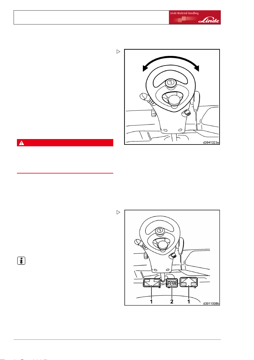
4 Operation
Standard equipment
Steering system
Steering
The hydrostatic steering system means that
very little effort is required for the steering
wheel turning movement. This is particularly
advantageous when palletising in narrow
aisles.
¾ Starting and driving.
¾ Turn the steering wheel to the left and right
as far as it will go.
The steering wheel can be moved beyond
the stop if sufficient force is applied, without
the position of the wheels changing on the
steering axle.
DANGER
The forklift truck must not be driven if the steering
system is defective.
If the steering is stiff or has too much play, contact
your authorised dealer.
Brake system
Service brake
¾ Allow accelerator pedals (1) to move to the
neutral position.
The hydrostatic drive will act as a service
brake. Slow or quick release of the accelerator
pedals to the neutral position allows the
braking effect to be sensitively controlled,
from gentle to hard braking.
NOTE
For emergency braking, press the stop pedal
(2) positioned between the accelerator pedals.
This will result in full application of the brake.
Stop pedal
The stop pedal (2) is not a sensitive service
brake but a sharply applied parking brake. Its
use should be avoided whilst driving, because
this can cause the drive wheels to lock and, in
56 Operating Instructions – 394 807 10 01 EN – 07/2011
Page 69

certain circumstances, can cause the load to
slip from the fork arms.
In unfavourable situations, the engine can also
stall; as a result the "Do not start the engine"
symbol (3) appears in the display unit. A block
against repeat starting is active and the engine
cannot be started. Always leave the ignition
switched on until the "Do not start the engine"
symbol (3) goes out. In this time, the variable
displacement pump of the drive unit swivels
to the neutral position. Afterwards, the engine
can be started again.
NOTE
It is recommended that drivers familiarise
themselves with the function and effect of this
brake when there is no load on the truck. For
this purpose they should choose a route with
no other traffic, travelling at a low speed.
Parking brake
The multi-disc brakes are used as the parking
brake of the fork-lift truck.
Operating the parking brake
¾ Turn the parking brak
wise direction to the
The interlock (1) engages and the symbol in
the display unit lights up.
e lever (2) in a clock-
stop.
Operation 4
Standard equipment
Releasing the parking brake
NOTE
The multi-disc brake will release only if the
engine is running.
¾ Turn the parking brake lever (2) gently in a
clockwise direction to release the interlock.
Operating Instructions – 394 807 10 01 EN – 07/2011 57
Page 70

4 Operation
Standard equipment
¾ Press the button (1).
The parking brake is unlocked.
¾ Move the parking brake (2) down
the stop.
The symbol on the indicator unit will go out.
DANGER
The forklift truck must not be driven if the braking
system is defective.
Should there be any defects or wear apparent in
the brake system, please contact your authorised
dealer at once.
Signal horn
Operating the horn
The horn is used as a warning signal, e.g. at
blind spots and junctions.
¾ Push in the horn button (1) on the armrest
until the horn sounds.
as far as
58 Operating Instructions – 394 807 10 01 EN – 07/2011
Page 71

Joystick with central lever operation
WARNING
There is a risk of becoming trapped
between parts due to the moving lift
mast or the attachment.
Therefore, never reach into or enter
the lift mast or the area between the
lift mast and the truck.
The lifting system and attachments
should only ever be used for their
proper purpose.
Drivers must be instructed in the
handling of the lifting system and
attachments.
Bear the maximum lift height in mind.
NOTE
When working with a shovel, see "Using the
truck during shovel operation".
Operating the lift and tilt attachments
NOTE
On the version with central lever operation,
moving the joystick to an intermediate position
(approx. 45°) will activate both functions at the
same time (e.g. lifting and tilting).
¾ Take note of the switching symbols with
arrows.
The joystick must always be operated gently,
never jerkily. Moving the joystick determines
the lifting, lowering and tilt speed. After the
joystick is released, it automatically returns to
its initial position.
Operation 4
Standard equipment
NOTE
The joysticks only function when the engine is
running and the driver is sitting in the driver’s
seat.
Operating Instructions – 394 807 10 01 EN – 07/2011 59
Page 72

4 Operation
Standard equipment
Lifting the fork carriage
DANGER
There is an increased risk of falling and crushing
when lifting the lift mast.
Forthisreason,itisnotpermittedtostepontothe
raised fork arms.
¾ Push joystick (1) to the right.
Lowering the fork carriage
¾ Push joystick (1) to the left.
Tilting the lift mast forwards
¾ Push the joystick (1) forwards.
Tilting the lift mast back
¾ Pull the joystick (1) backwards.
Operating the attachments
Attachments can be fitted to the truck as
special equipment (e.g. sideshift, fork prong
positioner, clamp etc.). Refer to the working
pressure and operating instructions for the
attachment. An additional joystick (cross
lever) is attached for operation.
NOTE
Before fitting an attachment, depressurisation (special equipment) can be performed to
depressurise the hydraulic system for the auxiliary hydraulics so that the connection on the
attachment can be affixed to the connection
on the fork carriage (see "Depressurisation"
under special equipment).
60 Operating Instructions – 394 807 10 01 EN – 07/2011
Page 73

CAUTION
Attachments affect the load capacity and stability of
the truck.
Attachments that are not supplied with the truck
should only be used if the authorised dealer has
checked that the arrangement in terms of load
capacity and stability ensures safe operation.
NOTE
The methods of attachment operation described here are examples. The configuration
of the joystick may vary depending on your
truck’s equipment.
¾ Take note of the switching symbols with
arrows.
NOTE
For every attachment, a label stating the load
capacity of the truck plus attachment (for a
description, see "Additional capacity rating
plate for attachments") must be affixed within
the driver’s range of vision and a symbol label
for the relevant attachment must be affixed
behind the joystick.
Operation 4
Standard equipment
Operating the sideshift
NOTE
In order to prevent damage, do not activate
the sideshift when the fork arms are on the
ground.
¾ Push joystick (2) to the left.
Sideshift moves to the left.
¾ Push joystick (2) to the right.
Sideshift moves to the right.
Operating Instructions – 394 807 10 01 EN – 07/2011 61
Page 74

4 Operation
Standard equipment
Operating the fork prong positioner
NOTE
In order to prevent damage, do not activate
the fork prong positioner with a load, or with
the fork arms on the ground. Do not use the
fork prong positioner as a clamp.
¾ Push the joystick (2) forwards.
Fork arms move outwards.
¾ Pull the joystick (2) backwards.
Fork arms move inwards.
Operating the clamp
DANGER
Increased risk of accident from a falling load.
For attachments that perform a clamping function
(e.g. a bale clamp), a lockable joystick must be
used.
If your truck is not fitted with this equipment, please
contact your authorised dealer.
Version 1: Electronically locked
¾ Take note of the switching symbols with
arrows.
62 Operating Instructions – 394 807 10 01 EN – 07/2011
Page 75

¾ Push joystick (2) forwards by at least 40%
and then move to the zero position.
Joystick is unlocked for approx. one second
and the display (3) lights up in the display unit.
NOTE
If the joystick is
time period, it i
¾ Push the joystick (2) forwards.
Clamp opens.
Once the joystic
locked again wit
¾ Pull the joystick (2) backwards.
Clamp closes.
not moved forwards within this
s locked again.
k has been released, it is
hin one second.
Operation 4
Standard equipment
Version 2: Mechanically locked
NOTE
The joystick (single lever) is recognisable by
the somewhat wider design of the bellows.
Operating Instructions – 394 807 10 01 EN – 07/2011 63
Page 76

4 Operation
Standard equipment
¾ Take note of the switching symbols with
arrows.
¾ Unlock the joystick (4) (depending on the
version) by pressing the knob downwards.
¾ Push the joystick (4) forwards.
Clamp opens.
¾ Pull the joystick (4) backwards.
Clamp closes.
Once the joystick
locked again.
has been released, it is
64 Operating Instructions – 394 807 10 01 EN – 07/2011
Page 77

Joystick with single lever operation
WARNING
There is a risk of becoming trapped
between parts due to the moving lift
mast or the attachment.
Therefore, never reach into or enter
the lift mast or the area between the
lift mast and the truck.
The lifting system and attachments
should only ever be used for their
proper purpose.
Drivers must be instructed in the
handling of the lifting system and
attachments.
Bear the maximum lift height in mind.
NOTE
When working with a shovel, see "Using the
truck during shovel operation".
Operating the lift and tilt attachments
¾ Take note of the switching symbols with
arrows.
The joystick must always be operated gently,
never jerkily. Moving the joystick determines
the lifting, lowering and tilt speed. After the
joystick is released, it automatically returns to
its initial position.
Operation 4
Standard equipment
NOTE
The joysticks only function when the engine is
running and the driver is sitting in the driver’s
seat.
Operating Instructions – 394 807 10 01 EN – 07/2011 65
Page 78

4 Operation
Standard equipment
Lifting the fork carriage
DANGER
There is an increased risk of falling and crushing
when lifting the lift mast.
Forthisreason,itisnotpermittedtostepontothe
raised fork arms.
¾ Pull the joystick (1) backwards.
Lowering the fork carriage
¾ Push the joystick (1) forwards.
Tilting the lift mast forwards
¾ Push the joystick (2) forwards.
Tilting the lift mast back
¾ Pull the joystick (2) backwards.
Operating the attachments
Attachments can be fitted to the truck as
special equipment (e.g. sideshift, fork prong
positioner, rotator, clamp etc.). Refer to the
working pressure and operating instructions
for the attachment. Further joysticks are
fitted to the truck for the operation of the
attachments.
NOTE
Before fitting an attachment, depressurisation (special equipment) can be performed to
depressurise the hydraulic system for the auxiliary hydraulics so that the connection on the
attachment can be affixed to the connection
on the fork carriage (see "Depressurisation"
under special equipment).
66 Operating Instructions – 394 807 10 01 EN – 07/2011
Page 79

CAUTION
Attachments affect the load capacity and stability of
the truck.
Attachments that are not supplied with the truck
should only be used if the authorised dealer has
checked that the arrangement in terms of load
capacity and stability ensures safe operation.
NOTE
The methods of attachment operation described here are examples. The configuration
of the joystick may vary depending on your
truck’s equipment.
¾ Take note of the switching symbols with
arrows.
NOTE
For every attachment, a label stating the load
capacity of the truck plus attachment (for a
description, see "Additional capacity rating
plate for attachments") must be affixed within
the driver’s range of vision and a symbol label
for the relevant attachment must be affixed
behind the joystick.
Operation 4
Standard equipment
Operating the sideshift
NOTE
In order to prevent damage, do not activate
the sideshift when the fork arms are on the
ground.
¾ Push the joystick (3) forwards.
Sideshift moves to the left.
¾ Pull the joystick (3) backwards.
Sideshift moves to the right.
Operating Instructions – 394 807 10 01 EN – 07/2011 67
Page 80

4 Operation
Standard equipment
Operating the fork prong positioner
NOTE
In order to prevent damage, do not activate
the fork prong positioner with a load, or with
the fork arms on the ground. Do not use the
fork prong positioner as a clamp.
¾ Push the joystick (4) forwards.
Fork arms move outwards.
¾ Pull the joystick (4) backwards.
Fork arms move inwards.
Operating the rotator
NOTE
Ensure that there
the rotator is tu
damage occurrin
¾ Take note of the switching symbols with
arrows.
¾ Push the joystick (5) forwards.
Unit moves antic
¾ Pull the joystick (5) backwards.
Unit moves clockwise.
is sufficient distance when
rning, in order to prevent
g.
lockwise.
Operating the clamp
DANGER
Increased risk of accident from a falling load.
For attachments that perform a clamping function
(e.g. a bale clamp), a lockable joystick must be
used.
If your truck is not fitted with this equipment, please
contact your authorised dealer.
68 Operating Instructions – 394 807 10 01 EN – 07/2011
Page 81

Version 1: Electronically locked
¾ Take note of the switching symbols with
arrows.
¾ Push joystick (4) (depending on the version)
forwards by at least 40% and then move to
the zero position.
Operation 4
Standard equipment
Operating Instructions – 394 807 10 01 EN – 07/2011 69
Page 82

4 Operation
Standard equipment
Joystick is unlocked for approx. one second
and the display (6) lights up in the display unit.
NOTE
If the joystick is not moved f
time period, it is locked aga
¾ Push the joystick (4) forwards.
Clamp opens.
Once the joystick has been
locked again within one se
¾ Pull the joystick (4) backwards.
Clamp closes.
Version 2: Mechanically locked
NOTE
The joystick is recognisable by the somewhat
wider design of the bellows.
¾ Take note of the switching symbols with
arrows.
orwards within this
in.
released, it is
cond.
70 Operating Instructions – 394 807 10 01 EN – 07/2011
Page 83

¾ Unlock the joystick (4) (depending on the
version) by pressing the knob downwards.
¾ Push the joystick (4) forwards.
Clamp opens.
¾ Pull the joystick (4) backwards.
Clamp closes.
Once the joystick has been r
locked again.
eleased, it is
Operation 4
Special equipment
Special equipmen
Depressurisati
When replacing
connecting ope
release coupli
the hydraulic s
¾ Switch off the engine.
¾ Switch on the ignition.
¾ Actuate the jo
auxiliary hyd
¾ Unscrew the union nuts on the fork carriage.
¾ Screw on the lines from the attachment or
connect the plug connectors.
on
hydraulic components or
rating equipment to the quick-
ngs of the working hydraulics,
ystem must be depressurised.
ystick of the corresponding
raulics repeatedly.
t
Operating Instructions – 394 807 10 01 EN – 07/2011 71
Page 84

4 Operation
Special equipment
Driver’s cab
Opening the cab door
¾ Push handle (4) upwards.
¾ Open driver’s door outwards.
Closingthecabdoor
NOTE
To make it easier to close the door, open the
side window slightly.
¾ Grip the rod (5) and pull the door towards
you until the interlock engages.
Opening/closing the front side window
¾ Press the interlock (3) upwards.
¾ Keep the interlock pressed, slide the side
window into the desired position until it
engages in one of the grooves (2).
Follow a similar procedure to close the side
window.
Opening/closing the rear side window
¾ Press the interlock (1) upwards.
¾ Keep the interlock pressed, slide the side
window into the desired position until it
engages in one of the grooves (2).
Follow a similar procedure to close the side
window.
Lighting
NOTE
The arrangement of the individual switches
on the overhead console on the upper righthand side of the overhead guard may vary,
depending on the version. Observe the switch
symbols.
72 Operating Instructions – 394 807 10 01 EN – 07/2011
Page 85

Switching on the interior lighting
¾ Press toggle switch (1).
Switching on the lighting.
¾ Move toggle switch (2) to cent
The sidelights and licence
switched on.
¾ Switch toggle switch (2) as far as it will go.
The dipped beams, sidelights and licence
plate lights are switched on.
re position.
plate light are
Switchingontheworkingspotlights.
¾ Press toggle switch (3) or (4) (depending on
the version).
Switching on the hazard warning system
¾ Press toggle switch (5)
.
Operation 4
Special equipment
Switch on rotating flas
Depending on the equipment there are two
different versions.
Version 1 (single stage switch):
¾ Press toggle switch
The rotating flashing light is always switched
on.
Version2(twostageswitch):
¾ Move toggle switch
The rotating flashing light is switched on only
when reversing.
¾ Switch toggle switch (6) as far as it will go.
The rotating flas
on.
Operating Instructions – 394 807 10 01 EN – 07/2011 73
hing light is always switched
hing light
(6).
(6) to centre position.
Page 86

4 Operation
Special equipment
Switchingonthedirectionindicators
¾ Move operating lever (7) on steering wheel
forwards.
The flashing lights flash on the r
lamp (8) flashes.
¾ Move operating lever (7 ) on steering wheel
backwards.
The flashing lights flash on the left. Indicator
lamp (8) flashes.
Windscreen wiper
NOTE
The various wiper functions can be turned both
on and off using the central actuating lever (1)
depending on what has been preselected at
the relevant toggleswitches (2, 3); it is different
for forwards and reverse travel.
ight. Indicator
Switching on the front windscreen wiper
Truck at a standstill or in forwards travel:
¾ Switch toggl
position.
74 Operating Instructions – 394 807 10 01 EN – 07/2011
eswitch(2)and(3)tothezero
Page 87

¾ Move the actuating lever (1) on the steering
wheel upwards from the centre position.
The front windscreen wiper remains in intermittent mode as long as the lever is actuated.
¾ Press the actuating lever (1) o
wheel downwards from the centr
The front windscreen wiper is in intermittent
mode.
n the steering
e position.
Switching on the rear window wiper
Truck in reverse travel:
¾ Switch toggle switch (2) an
position.
¾ Move the actuating lever (1) on the steering
wheel upwards from the centre position.
The rear window wiper remains in intermittent
mode as long as the lever is actuated.
¾ Press the actuating leve
wheel downwards from t
The rear window wiper is in intermittent mode.
d (3) to the zero
r (1) on the steering
he centre position.
Switching on the front windscreen wiper
and rear window wiper
¾ Move toggle switch (2) to centre position.
Truck at a standstil
¾ Move the actuating lever (1) on the steering
wheel upwards from the centre position.
As long as the lever is actuated, the front
windscreen wiper remains in continuous
mode and the rear window wiper remains
in intermittent mode.
¾ Press the actuati
wheel downwards f
The front windscreen wiper is in continuous
mode and the rear window wiper is in intermittent mode.
Truck in reverse travel:
lorinforwardstravel:
ng lever (1) on the steering
rom the centre position.
Operation 4
Special equipment
Operating Instructions – 394 807 10 01 EN – 07/2011 75
Page 88

4 Operation
Special equipment
¾ Move the actuating lever (1) on the steering
wheel upwards from the centre position.
As long as the lever is actuated, the front
windscreen wiper remains in intermittent
mode and the rear window wiper remains
in continuous mode.
¾ Press the actuating lever (1
wheel downwards from the cen
The front windscreen wiper is in intermittent
mode and the rear window wiper is in continuous mode.
Truck at a standstill or in forwards/reverse
travel:
¾ Switch toggle switch (2) a
¾ Move the actuating lever (1) on the steering
wheel upwards from the centre position.
As long as the lever is actuated, the front
windscreen wiper and rear window wiper
remain in continuous mode.
¾ Press the actuating lever (1) on the steering
wheel downwards from the centre position.
The front windscreen wi
wiper are in continuous
) on the steering
tre position.
s far as it will go.
per and rear window
mode.
Switching on the front
windscreen wiper
and roof panel wiper
¾ Move toggle switch (3) to centre position.
¾ Move the actuating lever (1) on the steering
wheel upwards from the centre position.
As long as the lever i
windscreen wiper an
in intermittent mod
¾ Press the actuating lever (1) on the steering
wheel downwards from the centre position.
The front windscreen wiper and roof panel
wiper are in intermittent mode.
¾ Switch toggle swit
¾ Move the actuating lever (1) on the steering
wheel upwards from the centre position.
As long as the lever is actuated, the front
windscreen wiper remains in intermittent
76 Operating Instructions – 394 807 10 01 EN – 07/2011
s actuated, the front
d roof panel wiper remain
e.
ch (3) as far as it will go.
Page 89

mode and the roof panel wiper remains in
continuous mode.
¾ Press the actuating lever (1) on the steering
wheel downwards from the centre position.
The front windscreen wiper is i
mode and the roof panel wiper is
mode.
n intermittent
in continuous
Operation 4
Special equipment
Switching on the wiper/was
¾ Press the actuating lever (1) fully in.
The wiper/washer system is activated for the
windscreen and rear window as long as the
lever is pressed.
¾ Switch on the toggle swit
The wiper/washer system is activated for the
windscreen, rear window and roof panel as
long as the lever is pressed.
her system
ch (3).
Window heater
Switching on t
¾ Press push button (1).
The rear window heating is in operation for
15 minutes.
¾ Actuate push b
operation.
The rear window heating is switched off.
¾ Briefly actuate push button (1) 2x during the
heating operation.
The rear win
further 15 m
he rear window heating
utton (1) during the heating
dow heating is in operation for a
inutes.
Operating Instructions – 394 807 10 01 EN – 07/2011 77
Page 90

4 Operation
Special equipment
Heating system, air conditioning
Heating system operating devices
• Turning knob (1) for temperature control
• Turning knob (2) for setting t
positions
• Rotary switch (3) for setting the vent positions for windscreen defrosting / footwell
ventilation
• Cab air vents (4)
Switching on the heating system
¾ Turn switch (2).
The blower is swi
air flow settings
tched on and there are three
.
he blower
Defrosting the w
¾ For maximum defrosting, set the
• Turning knob (1) to the far right position
• Turning knob (
ing position (
• Rotary switch (2) to level 3
• Cab air vents (4) to open, fins forwards
For normal hea
rules apply:
• Select the temperature using turning knob
(1) (far left → cold / far right → hot)
• Use the blower switch (2) (level 1 to 3), air
distribution vent (turning knob (3)) and cab
air vents (4) to select the temperature and
temperature distribution
78 Operating Instructions – 394 807 10 01 EN – 07/2011
indows
3) to the windscreen defrost-
far left position)
ting operation, the following
Page 91

Air conditioning operating devices
• Turning knob (5) for temperature control
• Function display (6)
• Push-button (7) for switching the air conditioning on
• Rotary switch (8) for setting the blower
positions
• Turning knob (9) for setting
tions for windscreen defros
ventilation
• Cab air vents (10)
the vent posi-
ting / footwell
Switching on the air conditioning
CAUTION
The moving parts must be lubricated and the
compressor prevented from seizing.
Therefore switch on the air conditioning briefly
every 3 months. In addition, the air conditioning
must be serviced once a year by your authorised
dealer, preferably before the season starts, and a
record must be kept of the servicing. Otherwise, the
warranty will be void.
NOTE
It is normal for condensation water to build up
in the hoses and under the truck when the air
conditioning is in operation.
¾ Turn switch (8).
The blower is switched on and there are three
air flow settings.
Operation 4
Special equipment
NOTE
The air conditioning only works when the
engine is running and the blower switch is
switched on (setting 1, 2 or 3). The fans in
the roof switch on when necessary. They can
come to a standstill from time to time.
¾ Switch on push-button (7).
The function display (6) lights up green.
To raise the temperature in the cab:
¾ Rotate turning knob (5) clockwise and
reduce the blower speed using switch (8).
To lower the temperature in the cab:
Operating Instructions – 394 807 10 01 EN – 07/2011 79
Page 92

4 Operation
Special equipment
¾ Close windows and doors, rotate turning
knob (5) anti-clockwise and increase the
blower speed using switch (8).
NOTE
To achieve maximum cooling i
•
the air conditioning must b
•
the turning knob (5) must be fully turned to
the left stop,
•
the blower must be set to its highest blower
position,
•
the windows and doors must
NOTE
On cool, humid days, the
conditioning can be use
air in the cab (operate t
air conditioning simul
taneously). The truck
heating system counter
This ensures a pleasant
the cab and reduces fog
n the cab:
e switched on,
be closed.
heater and air
d to dehumidify the
he heating system and
acts the cooling effect.
temperature inside
ging on the windows.
80 Operating Instructions – 394 807 10 01 EN – 07/2011
Page 93

Linde Forklift Data Management (LFM)
Truck data acquisition
The truck data acquisition (FDE) input device
(1) is located in the armrest console (3).
The input device has a 12-di
With the standard setting, a 5-digit PIN is
allocated to the respective driver to ensurethat
the truck can only be operated by authorised
personnel.
The truck can only be started after entering this
PIN and possibly a status code (depending on
the setting).
NOTE
The PIN can be extended from 5 to 8 digits.
Before entering the PIN, please contact your
fleet manager to check the number of digits in
the PIN and to find out about the truck settings.
Status code
NOTE
The code indicates the status of the truck.
The following codes are available:
0
•
=TruckOK
1
= Request service (truck will not start)
•
2
•
= Request maintenance (truck starts)
3
•
= Problem with driving
4
= Problem with lifting
•
5
•
= Problem with steering
6
•
= Accident damage
7
= User-defined
•
8
•
= User-defined
9
•
= User-defined
The status messages
defined individually by the user. Please
contact your fleet manager to find out the
definition of these status messages.
git keypad (2).
7,8
and9can be
Operation 4
Special equipment
Operating Instructions – 394 807 10 01 EN – 07/2011 81
Page 94

4 Operation
Special equipment
NOTE
If you only notice one of these s
as a problem with driving) afte
the status code
0
(truck OK), you
off.
¾ Rotate the turning knob (6) anticlockwise to
the stop.
¾ Log in again with status message
lem with driving)
tatuses (such
r you have input
have to log
3
(prob-
Truck data acquis
setting (PIN and
Logging on and starting the truck:
¾ Apply the parking brake.
¾ Flip up the armr
to the right via
82 Operating Instructions – 394 807 10 01 EN – 07/2011
ition — standard
status code)
est support (4) on the side
opening (5).
Page 95

¾ Press the*(4) button to start the input
device.
The green LED (2) flashes.
0 0
¾ Enter personal PIN (factory se
0 0 0
) and status code.
Therefore, for a properly set-up truck, the PIN
should be as follows:
NOTE
0 0 0 0 0 0
If the PIN was input incorrectly, press the
tting =
.
*
button (4) and enter the correct PIN.
¾ Confirm the entry with the#button (3).
The green LED (2) lights u
NOTE
p with a steady light.
If the red LED (1) lights up, an incorrect PIN
was entered. Press the
*
button (4) and enter
it again. If more than three incorrect entries
are made (factory setting), the red LED (1)
lights up and the green LED (2) flashes. The
input of a valid PIN is blocked for 10 minutes.
The blocking time can be interrupted by
inputting a special PIN. Please contact your
fleet manager.
¾ Rotate the turning kn
stop and start the tru
ob (6) clockwise to the
ck.
Operation 4
Special equipment
NOTE
If the truck does not start properly the first time,
the starting procedure can be repeated until
the turning knob (6) is returned to the zero
position, and the PIN is discarded after expiry
of the delay time.
NOTE
If the green (2)
as steady light
Please inform y
Operating Instructions – 394 807 10 01 EN – 07/2011 83
and red (1) LEDs both light up
s, the data must be read out.
our fleet manager at once.
Page 96

4 Operation
Special equipment
Switch off the truck and log off:
¾ Rotate the turning knob (6) anticlockwise to
the stop.
The engine is turned off.
NOTE
After a delay time (factory setting = 10 seconds) the red LED (1) lights up briefly, and
the green (2) and red (1) LEDs then flash for
approx. 3 seconds. During this period, the
truck can be started at any time. The LEDs
then go out, and the PIN is discarded. The
delay time can be set to between 10 seconds
and 10 minutes using the diagnostic device.
Please contact your authorised dealer.
Pressing the#button (3) a
off the engine terminate
immediately and the PIN i
fter switching
s the delay time
s deleted.
Truck data acquisition
— special setting
(PIN)
Logging on and starting the truck:
¾ Apply the parking brake.
¾ Flip up the armrest su
to the right via openi
84 Operating Instructions – 394 807 10 01 EN – 07/2011
pport (4) on the side
ng (5).
Page 97

¾ Press the*(4) button to start the input
device.
The green LED (2) flashes.
0 0
¾ Enter personal PIN (factory se
0 0 0
).
NOTE
If the PIN was input incorrectly, press the
tting =
*
button (4) and enter the correct PIN.
¾ Confirm the entry with the#b
The green LED (2) lights up with a steady light.
NOTE
If the red LED (1) light
s up, an incorrect PIN
was entered. Press the
it again. If more than t
are made (factory sett
lights up and the green
input of a valid PIN is b
Theblockingtimecan
inputting a special P
hree incorrect entries
ing), the red LED (1)
LED (2) flashes. The
locked for 10 minutes.
be interrupted by
IN. Please contact your
utton (3).
*
button (4) and enter
fleet manager.
¾ Rotate the turning knob (6) clockwise to the
stop and start the truck.
Operation 4
Special equipment
NOTE
If the truck does not start properly the first time,
the starting procedure can be repeated until
the turning knob (6) is returned to the zero
position, and the PIN is discarded after expiry
of the delay time.
NOTE
If the green (2) and red (1) LEDs both light up
as steady lights, the data must be read out.
Please inform your fleet manager at once.
Operating Instructions – 394 807 10 01 EN – 07/2011 85
Page 98

4 Operation
Special equipment
Switch off the truck and log off:
¾ Rotate the turning knob (6) anticlockwise to
the stop.
The engine is turned off.
NOTE
After a delay time (factory setting = 10 seconds) the red LED (1) lights up briefly, and
the green (2) and red (1) LEDs then flash for
approx. 3 seconds. During this period, the
truck can be started at any time. The LEDs
then go out, and the PIN is discarded. The
delay time can be set to between 10 seconds
and 10 minutes using the diagnostic device.
Please contact your authorised dealer.
Pressing the#button (3) a
off the engine terminate
immediately and the PIN i
fter switching
s the delay time
s deleted.
Truck data acquisition
(chip or magnetic stri
NOTE
with a transponder
pcard)
The input device has a field (3) onto which the
corresponding transponder (chip or magnetic
strip card) must be placed. Only then can the
truck be started.
86 Operating Instructions – 394 807 10 01 EN – 07/2011
Page 99

Logging on and starting the truck:
¾ Apply the parking brake.
¾ Fold open the armrest support o
to the right.
¾ Place the valid transponder on the field (3).
Data is read in and the green LED (2) lights up
with a steady light.
¾ Remove transponder.
NOTE
n the side
If the red LED (1) lights up, the transponder is
invalid or there was a reading error. The input
device is reactivated automatically when a
valid transponder is used and read in.
¾ Rotate the turning knob (6) clockwise to the
stop and start the truck.
NOTE
If the truck does not
the starting proced
the turning knob (6)
start properly the first time,
ure can be repeated until
is returned to the zero
position.
Operation 4
Special equipment
NOTE
If the green (2) and red (1) LEDs both light up
as steady lights, the data must be read out.
Please inform your fleet manager at once.
Operating Instructions – 394 807 10 01 EN – 07/2011 87
Page 100

4 Operation
Special equipment
Switch off the truck and log off:
¾ Rotate the turning knob (6) anticlockwise to
the stop.
The engine is turned off.
NOTE
After a delay time (factory setting = 10 seconds) the red LED (1) lights up briefly, and
the green (2) and red (1) LEDs then flash for
approx. 3 seconds. During this period, the
truck can be started at any time. The LEDs
then go out, and the PIN is discarded. The
delay time can be set to between 10 seconds
and 10 minutes using the diagnostic device.
Please contact your authorised dealer.
Adjusting the driver’s seat with
rotating device
CAUTION
The driver’s seat must not rotate while the truck is
in use.
It should therefore be ensured that the rotating
device is locked.
The driver’s seat with rotating device offers
better rear visibility during reverse travel over
long distances.
When driving forwards over long distances, it
is recommended that you return the seat to the
straight-ahead position.
The rotating device is maintenance free.
88 Operating Instructions – 394 807 10 01 EN – 07/2011
 Loading...