


PRO-CUT 25

SVM149-A
October, 2006
Safety Depends on You
Lincoln arc welding and cutting
equipment is designed and built
with safety in mind. However,
your overall safety can be
increased by proper installation
. . . and thoughtful operation on
your part. DO NOT INSTALL,
OPERATE OR REPAIR THIS
EQUIPMENT WITHOUT READ-
ING THIS MANUAL AND THE
SAFETY PRECAUTIONS CON-
TAINED THROUGHOUT. And,
most importantly, think before
you act and be careful.
SERVICE MANUAL
For use with machine code numbers 10661
PRO-CUT 25
Return to Master TOC Return to Master TOC Return to Master TOC Return to Master TOC
View Safety Info View Safety Info View Safety Info View Safety Info
• Sales and Service through Subsidiaries and Distributors Worldwide •
Cleveland, Ohio 44117-1199 U.S.A. TEL: 1-888-935-3877 FAX: 216.486.1751 WEB SITE: www.lincolnelectric.com
• World's Leader in Welding and Cutting Products •
Copyright © 2006 Lincoln Global Inc.
RETURN TO MAIN MENU
Return to Master TOC Return to Master TOC Return to Master TOC Return to Master TOC
PROTECT YOURSELF AND OTHERS FROM POSSIBLE SERIOUS INJURY OR DEATH. KEEP CHILDREN
AWAY. PACEMAKER WEARERS SHOULD CONSULT WITH THEIR DOCTOR BEFORE OPERATING.
Read and understand the following safety highlights. For additional safety information it is strongly recommended that you pur-
chase a copy of “Safety in Welding & Cutting - ANSIStandard Z49.1” from the American Welding Society, P.O. Box 351040,
Miami, Florida 33135 or CSA Standard W117.2.
BE SURE THAT ALL INSTALLATION, OPERATION, MAINTENANCE, AND REPAIR PROCEDURES ARE
PERFORMED ONLY BY QUALIFIED INDIVIDUALS.
CUTTING SPARKS can
cause fire or explosion.
4.a..Remove fire hazards from the plasma cutting
or gouging area. If this is not possible, cover them
to prevent the cutting or gouging sparks from
starting a fire. Remember that welding sparks
and hot materials from plasma cutting or gouging can easily
go through small cracks and openings to adjacent areas.
Avoid cutting or gouging near hydraulic lines. Have a fire
extinguisher readily available.
4.b. Where compressed gases are to be used at the job site, spe-
cial precautions should be used to prevent hazardous situa-
tions. Refer to “Safety in Welding and Cutting” (ANSI Standard
Z49.1) and the operating information for the equipment being
used.
ARC RAYS can burn.
2.a. Use safety glasses and a shield with the prop-
er filter and cover plates to protect your eyes from
sparks and the rays of the arc when performing or
observing plasma arc cutting or gouging.
Glasses,headshield and filter lens should conform
to ANSI Z87. I standards.
2.b. Use suitable clothing including gloves made from durable
flame-resistant material to protect your skin and that of your
helpers from the arc rays.
2.c. Protect other nearby personnel with suitable non-flammable
screening and/or warn them not to watch the arc nor expose
themselves to the arc rays or to hot spatter or metal.
ELECTRIC SHOCK can kill.
1.a. The electrode and work (or ground) circuits
are electrically “hot” when the power source is on.
Do not touch these “hot” parts with your bare skin
or wet clothing. Wear dry, hole-free gloves to insu-
late hands.
1.b. When the power source is operating voltages in excess of 250
volts are produced. This creates the potential for serious elec-
trical shock - potentially even fatal.
1.c. Insulate yourself from work and ground using dry insulation.
When cutting or gouging in damp locations, on metal frame-
work such as floors, gratings or scaffolds and when in posi-
tions such as sitting or lying, make certain the insulation is
large enough to cover your full area of physical contact with
work and ground.
1.d. Always be sure the work cable makes a good electrical con-
nection with the metal being cut or gouged. The connection
should be as close as possible to the area being cut or
gouged.
1.e. Ground the work or metal to be cut or gouged to a good elec-
trical (earth) ground.
1.f. Maintain the plasma torch, cable and work clamp in good, safe
operating condition. Replace damaged insulation.
1.g. Never dip the torch in water for cooling or plasma cut or gouge
in or under water.
1.h. When working above floor level, protect yourself from a fall
should you get a shock.
1.i. Operate the pilot arc with caution. The pilot arc is capable of
burning the operator, others or even piercing safety clothing.
1.j. Also see Items 4c and 6.
PLASMA CUTTING or GOUGING can be hazardous.
FUMES AND GASES
can be dangerous.
3.a. Plasma cutting or gouging may produce
fumes and gases hazardous to health. Avoid
breathing these fumes and gases. When cutting
or gouging, keep your head out of the fumes. Use
enough ventilation and/or exhaust at the arc to
keep fumes and gases away from the breathing zone. When
plasma cutting or gouging on lead or cadmium plated
steel and other metals or coatings which produce highly
toxic fumes keep exposure as low as possible and below
Threshold Limit Values (TLV) using local exhaust or
mechanical ventilation. In confined spaces or in some
circumstances, outdoors, a respirator may be required.
Additional precautions are also required when plasma
cutting or gouging on galvanized steel.
3. b. The operation of plasma cutting or gouging fume control
equipment is affected by various factors including proper use
and positioning of the equipment, maintenance of the equip-
ment and the specific procedure and applicaiton involved.
Worker exposure level should be checked upon installation
and periodically thereafter to be certain it is within applicable
OSHA PEL and ACGIH TLV limits.
3.c. Do not use plasma cutting or gouging equipment in locations
near chlorinated hydrocarbon vapors coming from degreas-
ing, cleaning or spraying operations. The heat and rays of the
arc can react with solvent vapors to form phosgene, a highly
toxic gas, and other irritating products.
3.d. Gases used for plasma cutting and gouging can displace air
and cause injury or death. Always use enough ventilation,
especially in confined areas, to insure breathing air is safe.
3.e. Read and understand the manufacturer’s instructions for this
equipment and follow your employer’s safety practices.
Aug. ‘06
i
SAFETY
i
Return to Master TOC Return to Master TOC Return to Master TOC Return to Master TOC
4.c. When not cutting or gouging, make certain no part of the elec-
trode circuit is touching the work or ground. Accidental contact
can cause overheating and create a fire hazard.
4.d. Do not cut or gouge tanks, drums or containers until the proper
steps have been taken to insure that such procedures will not
cause flammable or toxic vapors from substances inside. They
can cause an explosion even though they have been “cleaned.”
For information purchase “Recommended Safe Practices for
the Preparation for Welding and Cutting of Containers and
Piping That Have Held Hazardous Substances”, A WSF4.1 from
the American Welding Society (see address above).
4.e. Vent hollow castings or containers before heating, cutting or
gouging. They may explode.
4.f. Do nor fuel engine driven equipment near area where plasma
cutting or gouging.
4.g. Sparks and spatter are thrown from the plasma arc. Wear safe-
ty glasses, ear protection and oil free protective garments such
as leather gloves, heavy shirt, cuffless trousers, high shoes
and a cap over your hair. Wear ear plugs when cutting or goug-
ing out of position or in confined places. Always wear safety
glasses with side shields when in a cutting or gouging area.
4.h. Connect the work cable to the work as close to the cutting or
gouging area as practical. Work cables connected to the build-
ing framework or other locations away from the cutting or goug-
ing area increase the possibility of the current passing through
lifting chains, crane cables or other alternate circuits. This can
create fire hazards or overheat lifting chains or cables until they
fail.
FOR ELECTRICALLY
powered equipment.
6.a. Turn off input power using the disconnect
switch at the fuse box before working on the
equipment.
6.b. Install equipment in accordance with the U.S. National
Electrical Code, all local codes and the manufacturer’s rec-
ommendations.
6.c. Ground the equipment in accordance with the U.S. National
Electrical Code and the manufacturer’s recommendations.
CYLINDER may explode
if damaged.
5.a. Use only compressed gas cylinders contain-
ing the correct gas for the process used and
properly operating regulators designed for the
gas and pressure used. All hoses, fittings, etc.
should be suitable for the application and maintained in good
condition.
5.b. Always keep cylinders in an upright position securely chained
to an undercarriage or fixed support.
5.c. Cylinders should be located:
• Away from areas where they may be struck or subjected to
physical damage.
• Asafe distance from plasma cutting or gouging, arc weld-
ing operations and any other source of heat, sparks,
or flame.
5.d. Never allow any part of the electrode, torch or any other elec-
trically “hot” parts to touch a cylinder.
5.e. Keep your head and face away from the cylinder valve outlet
when opening the cylinder valve.
5.f. Valve protection caps should always be in place and hand
tight except when the cylinder is in use or connected for use.
5.g. Read and follow the instructions on compressed gas cylin-
ders, associated equipment, and CGA publication P-l,
“Precautions for Safe Handling of Compressed Gases in
Cylinders,”available from the Compressed Gas Association
1235 Jefferson Davis Highway, Arlington, VA22202.
Apr. ‘93
ELECTRIC AND MAGNETIC FIELDS
may be dangerous
8.a. Electric current flowing through any conduc-
tor causes localized Electric and Magnetic Fields
(EMF). Cutting or gouging current creates EMF
fields around torch cables and cutting machines.
8.b. EMF fields may interfere with some pace-
makers, so operators having a pacemaker
should consult their physician before cutting or
gouging.
8.c. Exposure to EMF fields during cutting or gouging may have
other health effects which are now not known.
8d. All operators should use the following procedures in order to
minimize exposure to EMF fields from the cutting or gouging
circuit:
8.d.1. Route the torch and work cables together - Secure
them with tape when possible.
8.d.2. Never coil the torch cable around your body.
8.d.3. Do not place your body between the torch and
work cables. If the torch cable is on your right side,
the work cable should also be on your right
side.
8.d.4. Connect the work cable to the workpiece as close as
possible to the area being cut or gouged.
8.d.5. Do not work next to cutting power source.
PLASMA ARC can injure.
7.a. Keep your body away from nozzle and
plasma arc.
7.b. Operate the pilot arc with caution. The pilot arc is capable of
burning the operator, others or even piercing safety clothing.
ii
SAFETY
ii

SAFETY
iii iii
Return to Master TOC Return to Master TOC Return to Master TOC Return to Master TOC
PRÉCAUTIONS DE SÛRETÉ
Pour votre propre protection lire et observer toutes les instructions
et les précautions de sûreté specifiques qui parraissent dans ce
manuel aussi bien que les précautions de sûreté générales suiv-
antes:
Sûreté Pour Soudage A L’Arc
1. Protegez-vous contre la secousse électrique:
a. Les circuits à l’électrode et à la piéce sont sous tension
quand la machine à souder est en marche. Eviter toujours
tout contact entre les parties sous tension et la peau nue
ou les vétements mouillés. Porter des gants secs et sans
trous pour isoler les mains.
b. Faire trés attention de bien s’isoler de la masse quand on
soude dans des endroits humides, ou sur un plancher met-
allique ou des grilles metalliques, principalement dans
les positions assis ou couché pour lesquelles une grande
partie du corps peut être en contact avec la masse.
c. Maintenir le porte-électrode, la pince de masse, le câble de
soudage et la machine à souder en bon et sûr état defonc-
tionnement.
d.Ne jamais plonger le porte-électrode dans l’eau pour le
refroidir.
e. Ne jamais toucher simultanément les parties sous tension
des porte-électrodes connectés à deux machines à souder
parce que la tension entre les deux pinces peut être le total
de la tension à vide des deux machines.
f. Si on utilise la machine à souder comme une source de
courant pour soudage semi-automatique, ces precautions
pour le porte-électrode s’applicuent aussi au pistolet de
soudage.
2. Dans le cas de travail au dessus du niveau du sol, se protéger
contre les chutes dans le cas ou on recoit un choc. Ne jamais
enrouler le câble-électrode autour de n’importe quelle partie du
corps.
3. Un coup d’arc peut être plus sévère qu’un coup de soliel, donc:
a. Utiliser un bon masque avec un verre filtrant approprié ainsi
qu’un verre blanc afin de se protéger les yeux du rayon-
nement de l’arc et des projections quand on soude ou
quand on regarde l’arc.
b. Porter des vêtements convenables afin de protéger la peau
de soudeur et des aides contre le rayonnement de l‘arc.
c. Protéger l’autre personnel travaillant à proximité au
soudage à l’aide d’écrans appropriés et non-inflammables.
4. Des gouttes de laitier en fusion sont émises de l’arc de
soudage. Se protéger avec des vêtements de protection libres
de l’huile, tels que les gants en cuir, chemise épaisse, pan-
talons sans revers, et chaussures montantes.
5. Toujours porter des lunettes de sécurité dans la zone de
soudage. Utiliser des lunettes avec écrans lateraux dans les
zones où l’on pique le laitier.
6. Eloigner les matériaux inflammables ou les recouvrir afin de
prévenir tout risque d’incendie dû aux étincelles.
7. Quand on ne soude pas, poser la pince à une endroit isolé de
la masse. Un court-circuit accidental peut provoquer un
échauffement et un risque d’incendie.
8. S’assurer que la masse est connectée le plus prés possible de
la zone de travail qu’il est pratique de le faire. Si on place la
masse sur la charpente de la construction ou d’autres endroits
éloignés de la zone de travail, on augmente le risque de voir
passer le courant de soudage par les chaines de levage,
câbles de grue, ou autres circuits. Cela peut provoquer des
risques d’incendie ou d’echauffement des chaines et des
câbles jusqu’à ce qu’ils se rompent.
9. Assurer une ventilation suffisante dans la zone de soudage.
Ceci est particuliérement important pour le soudage de tôles
galvanisées plombées, ou cadmiées ou tout autre métal qui
produit des fumeés toxiques.
10. Ne pas souder en présence de vapeurs de chlore provenant
d’opérations de dégraissage, nettoyage ou pistolage. La
chaleur ou les rayons de l’arc peuvent réagir avec les vapeurs
du solvant pour produire du phosgéne (gas fortement toxique)
ou autres produits irritants.
11. Pour obtenir de plus amples renseignements sur la sûreté, voir
le code “Code for safety in welding and cutting” CSA Standard
W 117.2-1974.
PRÉCAUTIONS DE SÛRETÉ POUR
LES MACHINES À SOUDER À
TRANSFORMATEUR ET À
REDRESSEUR
1. Relier à la terre le chassis du poste conformement au code de
l’électricité et aux recommendations du fabricant. Le dispositif
de montage ou la piece à souder doit être branché à une
bonne mise à la terre.
2. Autant que possible, I’installation et l’entretien du poste seront
effectués par un électricien qualifié.
3. Avant de faires des travaux à l’interieur de poste, la debranch-
er à l’interrupteur à la boite de fusibles.
4. Garder tous les couvercles et dispositifs de sûreté à leur place.

MASTER TABLE OF CONTENTS FOR ALL SECTIONS
iv iv
PRO-CUT 25
Page
Safety .................................................................................................................................................i-iii
Installation .............................................................................................................................Section A
Technical Specifications .............................................................................................................A-2
Safety Precautions......................................................................................................................A-3
Select Proper Location ...............................................................................................................A-3
Stacking ......................................................................................................................................A-3
Tilting...........................................................................................................................................A-3
High Frequency Interference Protection.....................................................................................A-3
Input Electrical Connections.......................................................................................................A-3
Gas Input Connections ...............................................................................................................A-4
Output Connections....................................................................................................................A-5
Torch.....................................................................................................................................A-5
Operation...............................................................................................................................Section B
Safety Precautions ....................................................................................................................B-2
Description ................................................................................................................................B-2
Preheating Temperature .............................................................................................................B-2
User Responsibilities .................................................................................................................B-3
Operational Features and Controls ............................................................................................B-3
Design Features and Advantages ..............................................................................................B-3
Cutting Capability .......................................................................................................................B-4
Consumable Life.........................................................................................................................B-4
Limitations ..................................................................................................................................B-5
Controls and Settings.................................................................................................................B-5
Pilot Arc Discussion....................................................................................................................B-6
Procedure Recommendations....................................................................................................B-7
General.................................................................................................................................B-7
Suggestions For Extra Utility From The Pro-Cut System....................................................B-7
Accessories ..........................................................................................................................Section C
Maintenance .........................................................................................................................Section D
Theory of Operation .............................................................................................................Section E
Troubleshooting and Repair.................................................................................................Section F
How to Use Troubleshooting Guide............................................................................................F-2
Troubleshooting Guide ................................................................................................................F-4
Test Procedures ..........................................................................................................................F-9
Replacement Procedures .........................................................................................................F-29
Electrical Diagrams..............................................................................................................Section G
Parts Manual (Pro Cut 25)...............................................................................................P-357 Series
Cutting Torch ...................................................................................................P-210-U
RETURN TO MAIN MENU

PRO-CUT 25
Return to Master TOC Return to Master TOC Return to Master TOC Return to Master TOC
NOTES

TABLE OF CONTENTS
- INSTALLATION SECTION -
Section A-1 Section A-1
PRO-CUT 25
Installation
Technical Specifications .............................................................................................................A-2
Safety Precautions......................................................................................................................A-3
Select Proper Location...............................................................................................................A-3
Stacking......................................................................................................................................A-3
Tilting ..........................................................................................................................................A-3
High Frequency Interference Protection.....................................................................................A-3
Input Electrical Connections.......................................................................................................A-3
Gas Input Connections...............................................................................................................A-4
Output Connections ...................................................................................................................A-5
Torch.....................................................................................................................................A-5
Return to Master TOC Return to Master TOC Return to Master TOC Return to Master TOC
INSTALLATION
A-2 A-2
PRO-CUT 25
Return to Section TOC Return to Section TOC Return to Section TOC Return to Section TOC
Return to Master TOC Return to Master TOC Return to Master TOC Return to Master TOC
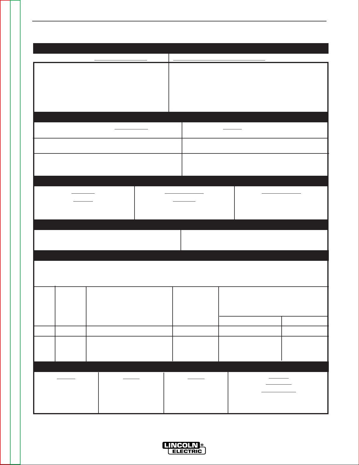
W
eight
Including
Torch Cable
35 lbs.
15.9 kg.
INPUT - SINGLE PHASE / 60 HERTZ ONLY
RATED OUTPUT
OUTPUT
RECOMMEND INPUT WIRE AND FUSE SIZES
REQUIRED GAS FLOW RATE REQUIRED GAS INLET PRESSURE
PHYSICAL DIMENSIONS
TECHNICAL SPECIFICATIONS - PRO-CUT 25 (K1756-1)
Standard Voltage
Duty Cycle
20% on 115 V
60% on 115 V
100% on 230 V
35% on 115 V
60% on 230 V
Current
Range
12-25 Amps
AC Input
Voltage
at
50/60
Hertz
230V-1Ø
115V-1Ø
115V-1Ø
115V-1Ø
Fuse
(Super Lag)
Circuit Breaker
(Delay Type)
20 AMPS
15 AMPS
20 AMPS
30 AMPS
#14 (2.5 mm
2
)
#12 (4 mm
2
)
#12 (4 mm
2
)
#12 (4 mm
2
)
2 Input Supply Wires
1 Ground Wire
#14 (2.5 mm
2
)
#12 (4 mm
2
)
#12 (4 mm
2
)
#12 (4 mm
2
)
Type 75
o
C
Copper Wire in Conduit
AWG (IEC) Sizes
Depth
16.1 in.
410 mm
W
idth
6.3 in.
160 mm
Height
10.2 in.
260 mm
Open Circuit
V
oltage
400 VDC
For all plasma cutting applications
Based on U.S. National Electrical Code
Ambient Temperature 30
o
C or Less
Pilot Current
12 Amps
AMPS
15 A
20 A
20 A
25 A
25 A
1Ø Input Current at Rated Output
115/230/1/50/60Hz 115 V : 15 A @ 20%
115 V : 26.7A@ 60%
115 V : 37.7A@ 35%
230 V : 15 A@100%
230 V : 19 A@ 60%
55 PSI @ 240 SCFH
( 3.8 Bar. @ 6800 LHR)
65 to 150 PSI
(4.5 Bar. TO 10.3 Bar.)
25 A
15 A
20 A
25 A
Output
Input Cord
Plug
Size
6-20P or 6-30P or 6-50P
5-15P* or 5-20P* or 5-30P or 5-50P
5-20P* or 5-30P or 5-50P
5-30P or 5-50P
* Included with machine

INSTALLATION
A-3 A-3
PRO-CUT 25
Return to Section TOC Return to Section TOC Return to Section TOC Return to Section TOC
Return to Master TOC Return to Master TOC Return to Master TOC Return to Master TOC
Read entire Installation Section before installing the
PRO-CUT 25.
SAFETY PRECAUTIONS
ELECTRIC SHOCK CAN KILL.
• Only qualified personnel
should install this machine.
•Turn the input power OFF
at the disconnect switch or
fuse box and discharge input
capacitors before working
inside the equipment.
• Do not touch electrically hot parts.
•Turn the PRO-CUT Power Switch OFF
when connecting power cord to input
power.
___________________________________________
SELECT PROPER LOCATION
Place the PRO-CUT 25 where clean cool air can freely
circulate in and out the side louvers. Dirt, dust or any
foreign material that can be drawn into the machine
should be kept at a minimum. Failure to observe these
precautions can result in excessive operating temper-
atures and nuisance shutdown of the machine.
A source of clean, dry air or nitrogen must be supplied
to the PRO-CUT 25. Oil in the air is a severe problem
and must be avoided. The supply pressure must be
between 80 and 150 psi. The flow rate is approximate-
ly 4.0 cfm (113 l/min.). Failure to observe these pre-
cautions could result in excessive operating tempera-
tures or damage to the torch.
STACKING
The PRO-CUT 25 cannot be stacked.
TILTING
The PRO-CUT 25 must be placed on a stable, level
surface so it will not topple over.
HIGH FREQUENCY INTERFERENCE
PROTECTION
The PRO-CUT 25 employs a touch start mechanism
for arc initiation which eliminates high frequency emis-
sions from the machine as compared with spark gap
and solid state type high frequency generators. Keep
in mind, though, that these machines may be used in
an environment where other high frequency generating
machines are operating. By taking the following steps,
high frequency interference into the Pro-Cut can be
minimized
(1) Make sure the power supply chassis is connected
to a good earth ground. The work terminal ground
does NOT ground the machine frame.
(2) Keep the work clamp isolated from other work
clamps that have high frequency.
(3) If the work clamp cannot be isolated, then keep the
clamp as far as possible from other work clamp
connections.
(4) When the machine is enclosed in a metal building,
several good earth driven electrical grounds
around the periphery of the building are recom-
mended.
Failure to observe these recommended installation
procedures may cause improper function of the Pro-
Cut or possibly even damage to the control system or
power supply components.
INPUT ELECTRICAL CONNECTIONS
The PRO-CUT 25 is rated for 115VAC or 230VAC
inputs and will automatically reconnect for the supplied
voltage. The machine is shipped from the factory for
operation on 115VAC 15 amp circuits. Use on 15 amp
branch circuits will limit cutting output as indicated by
the graphics around the output knob. If the output is set
at 20 amps or greater, the input fuse or circuit breaker
may “blow” in roughly 30 seconds or less (depending
on fuse or circuit breaker type).
To achieve 20 amp output with 115VAC input, replace
the 15 amp plug on the input cord with the supplied 20
amp plug, and connect the unit to a 20 amp branch cir-
cuit with super lag fuses (or equivalent breaker). To
install the supplied 20 amp plug: Connect the white
(neutral) wire under terminal clamp with silver screw,
and black (hot) wire under terminal clamp with brass
screw. Connect green wire under terminal clamp with
green screw. Tighten terminal wire clamp screws
securely.
WARNING

INSTALLATION
A-4 A-4
PRO-CUT 25
Return to Section TOC Return to Section TOC Return to Section TOC Return to Section TOC
Return to Master TOC Return to Master TOC Return to Master TOC Return to Master TOC
• Failure to wire as instructed may cause personal
injury or damage to equipment.
• To be installed or checked by an electrician or
qualified person only.
------------------------------------------------------------------------
Use of normal 20 amp household breakers may result
in over current trips. If breaker trips occur, reduce the
cutting current output until nuisance trips stop.
To achieve the full 25 amp output capability of the
machine with 115 VAC input, remove the 15 amp or 20
amp plug on the input cord and install a 30 amp or 50
amp plug designed for 115 VAC (NEMAstyle 5-30P or
5-50P). Follow the instructions included with the plug.
Connect to an appropriate branch circuit with a mating
receptacle.
The PRO-CUT 25 performs best when connected to
230VAC inputs. To change over to 230VAC operation,
install a 230VAC plug with a current rating equal to or
greater than 20 amps.
For use on engine drives, keep in mind the above input
draw restrictions and the following precaution.
The PRO-CUT 25 can be operated on engine driven
generators as long as the 230 volt auxiliary meets the
following conditions:
• The AC waveform peak voltage is below 400 volts*.
• The AC waveform frequency is between 45 and 65
Hz.
• The RMS voltage of the AC waveform is always
greater than 208VAC *.
*
for 115 VAC input divide these values in half
The following Lincoln engine drives meet these condi-
tions when run in the high idle mode:
Ranger 200 & 250 engine drives
Commander 300, 400, & 500 engine drives
Some engine drives do not meet these conditions (eg
Miller Bobcats, etc). Operation of the PRO-CUT 25 is
not recommended on engine drives not conforming to
these conditions. Such combinations may overvoltage
the PRO-CUT 25 power source.
GAS INPUT CONNECTIONS
Supply the PRO-CUT 25 with clean compressed air or
nitrogen.
• Supply pressure must be between 80 psi
and 150 psi.
• Flow rate should be approximately 4.0
cfm (113 I/min.).
NOTE: Oil in the air supply to the PRO-CUT 25 can
cause severe problems. Use only a clean air
supply.
•
Compressed gas can be supplied either through the air
fitting supplied with the machine or through the
1
/
4
-19
BSPP
thread at the rear of the machine. To use the air
fitting supplied with the machine (packaged in the con-
sumable kit), apply teflon tape to the fitting threads and
install the fitting in the port at the rear of the machine.
• If compressed air is being used, it is highly recom-
mended that an inline filter be installed in the air sup-
ply line ahead of the air connection to the PRO-CUT
25.
• A standard nominal 5 micron inline filter is recom-
mended; however, for optimum performance,select a
prefilter with a 3 micron absolute rating. If these filter
ratings are unavailable, anything with a rating less
than, or equal to, 20 micron would be acceptable to
use. In line filter elements will generally filter the air
with little restriction to the airflow until the element is
about 75% contaminated. After this point, there will
be a noticeable pressure drop in the line. Filter ele-
ments should be replaced when a pressure drop of 8-
10 psi is indicated; however, for optimum perfor-
mance of the PRO-CUT 25, the filter element should
be replaced at or before the pressure drop reaches 8
psi. Be sure to select a filter that will accommodate
the necessary flow rating for the PRO-CUT 25 as
specified in the Installation section of this instruction
manual under the Gas Input Connections heading.
WARNING

INSTALLATION
A-5 A-5
PRO-CUT 25
Return to Section TOC Return to Section TOC Return to Section TOC Return to Section TOC
Return to Master TOC Return to Master TOC Return to Master TOC Return to Master TOC
NOTE: When using nitrogen gas from a cylinder, the
cylinder must have a pressure regulator.
• Maximum psi from a nitrogen gas cylinder to
the PRO-CUT 25 regulator should never
exceed 150 psi.
• Install a hose between the nitrogen gas
cylinder regulator and the PRO-CUT 25
gas inlet
.
CYLINDER could explode if dam-
aged.
• Keep cylinder upright and chained
to a fixed support.
• Keep cylinder away from areas where it could be
damaged.
• Never lift machine with cylinder attached.
• Never allow the cutting torch to touch the cylinder.
• Keep cylinder away from live electrical parts.
• Maximum inlet pressure 150 psi.
__________________
OUTPUT CONNECTIONS
Torch
The PRO-CUT 25 is sent from the factory with a 15’
PCT 20 cutting torch installed. Additional cutting torch-
es can be ordered from the K1615 series. Hand-held
torches come with 15' or 25’ cables.
WARNING

NOTES
A-6 A-6
PRO-CUT 25
Return to Section TOC Return to Section TOC Return to Section TOC Return to Section TOC
Return to Master TOC Return to Master TOC Return to Master TOC Return to Master TOC

Section B-1 Section B-1
PRO-CUT 25
TABLE OF CONTENTS
- OPERATION SECTION -
Operation...............................................................................................................................Section B
Safety Precautions......................................................................................................................B-2
Description .................................................................................................................................B-2
Preheating Temperature .............................................................................................................B-2
User Responsibility ....................................................................................................................B-3
Operational Features and Controls ............................................................................................B-3
Design Features and Advantages...............................................................................................B-3
Cutting Capability .......................................................................................................................B-4
Consumable Life.........................................................................................................................B-4
Limitations...................................................................................................................................B-5
Controls and Settings.................................................................................................................B-5
Pilot Arc Discussion ...................................................................................................................B-6
Procedure Recommendations....................................................................................................B-7
General .................................................................................................................................B-7
Suggestions for Extra Utility From the Pro-Cut System......................................................B-7
Return to Master TOC Return to Master TOC Return to Master TOC Return to Master TOC
Return to Section TOC Return to Section TOC Return to Section TOC Return to Section TOC
Return to Master TOC Return to Master TOC Return to Master TOC Return to Master TOC
B-2
B-2
PRO-CUT 25
OPERATION
Read and understand this entire section before operat-
ing the machine.
SAFETY PRECAUTIONS
DESCRIPTION
The PRO-CUT 25 is a constant current, continuous
control plasma cutting power source. It provides supe-
rior and reliable starting characteristics, cutting visibili-
ty and arc stability. The control system has a safety
mechanism to insure that the nozzle and electrode are
in place before cutting or gouging. This is extremely
important due to the high voltages involved.
The PRO-CUT 25 comes standard with an air regula-
tor and pressure gauge. The machine also comes with
an input power cord. Hand-held torches are available
in 15' or 25' cable. Consumables are included with
each Pro-Cut purchase so that cutting can begin right
out of the box. Consumables can also be ordered as
individual packages.
The PRO-CUT 25 initiates the plasma arc with a sim-
ple, yet reliable, touch start mechanism. This system
eliminates many of the failure problems associated
with hi-frequency start systems.
PREHEAT TEMPERATURE FOR
PLASMA CUTTING
Preheat temperature control is not necessary in most
applications when plasma arc cutting or gouging.
Preheat temperature control may be necessary on high
carbon alloy steels and heat treated aluminum for crack
resistance and hardness control. Job conditions, pre-
vailing codes, alloy level, and other considerations may
also require preheat temperature control. The following
minimum preheat temperature is recommended as a
starting point. Higher temperatures may be used as
required by the job conditions and/or prevailing codes. If
cracking or excessive hardness occurs on the cut face,
higher preheat temperature may be required. The rec-
ommended minimum preheat temperature for plate
thickness up to 1/2" (12.7mm) is 70°F (21.1°C).
ELECTRIC SHOCK
can kill.
• Do not touch electrically live parts
or electrode with skin or wet
clothing.
• Insulate yourself from work and
ground.
• Always wear dry insulating
gloves.
FUMES AND GASES
can be dangerous.
• Keep your head out of fumes.
• Use ventilation or exhaust to
remove fumes from breathing
zone.
WELDING, CUTTING and
GOUGING SPARKS
can cause fire or explosion
• Keep flammable material away.
• Do not weld, cut or gouge on
containers that have held combustibles.
Observe additional Safety Guidelines detailed in
the beginning of this manual.
WARNING
ARC RAYS
can burn.
•Wear eye, ear and body
protection.
PLASMA ARC
can injure
• Keep your body away from nozzle
and plasma arc.
• Operate the pilot arc with caution. The
pilot arc is capable of burning the
operator, others or even piercing
safety clothing.

OPERATION
B-3 B-3
PRO-CUT 25
Return to Section TOC Return to Section TOC Return to Section TOC Return to Section TOC
Return to Master TOC Return to Master TOC Return to Master TOC Return to Master TOC
USER RESPONSIBILITY
Because design, fabrication, erection and cutting vari-
ables affect the results obtained in applying this type of
information, the serviceability of a product or structure
is the responsibility of the user. Variation such as plate
chemistry, plate surface condition (oil, scale), plate
thickness, preheat, quench, gas type, gas flowrate
and equipment may produce results different than
those expected. Some adjustments to procedures may
be necessary to compensate for unique individual con-
ditions. Test all procedures duplicating actual field con-
ditions.
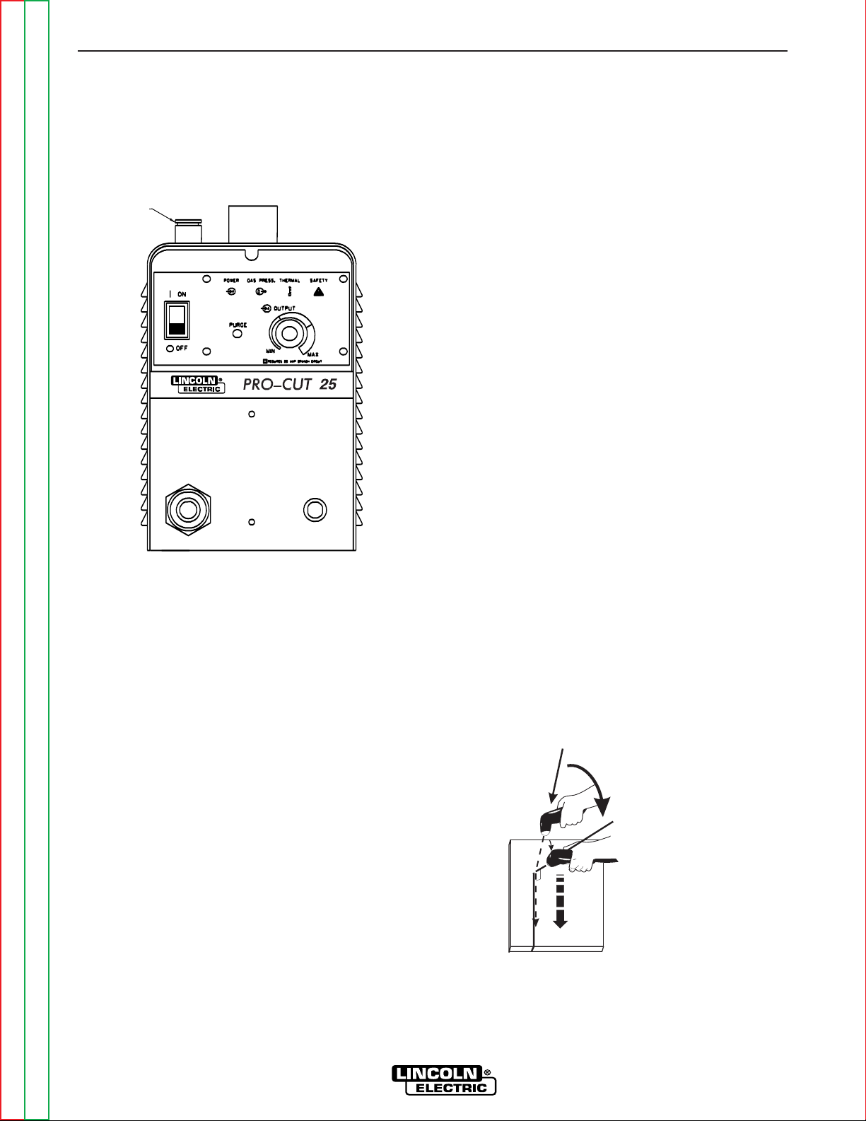
OPERATIONAL FEA TURES AND
CONTROLS
The PRO-CUT 25 comes with an ON/OFF POWER
SWITCH, OUTPUT CURRENT CONTROL, and
PURGE BUTTON.
DESIGN FEATURES AND
ADVANTAGES
The PRO-CUT 25 design makes plasma cutting
uncomplicated. This list of design features and advan-
tages will help you understand the machine's total
capabilities so that you can get maximum use from
your machine.
- Light weight and portable design for industrial use.
- Continuous control, 12 - 25 amps.
- Reliable touch start mechanism for plasma arc initia-
tion.
- Rapid arc restrike for fast cutting of expanded metal.
- Input over voltage protection.
- Bright 3.0 second timed pilot arc.
- Purge momentary push button.
- Air regulator and pressure gage included.
- Parts-in-Place mechanism to detect proper installa-
tion of consumables and torch.
- Latching Parts-in-Place mechanism. Requires the
operator to turn the machine off and then on to reset.
- Preflow/Postflow timing. Preflow is eliminated if arc
is re-initiated in Postflow.
- Thermostatic Protection.
- Solid state over-current protection.
- Automatic reconnect for 115 VAC or 230 VAC inputs.
- Dead front display for machine status.
- Unique electrode and Vortech™ nozzle design for
optimum cooling and long life.
- Swirl texture inside Vortech™ nozzle for better start-
ing reliability and higher quality cuts.
OPERATION
B-4 B-4
PRO-CUT 25
Return to Section TOC Return to Section TOC Return to Section TOC Return to Section TOC
Return to Master TOC Return to Master TOC Return to Master TOC Return to Master TOC
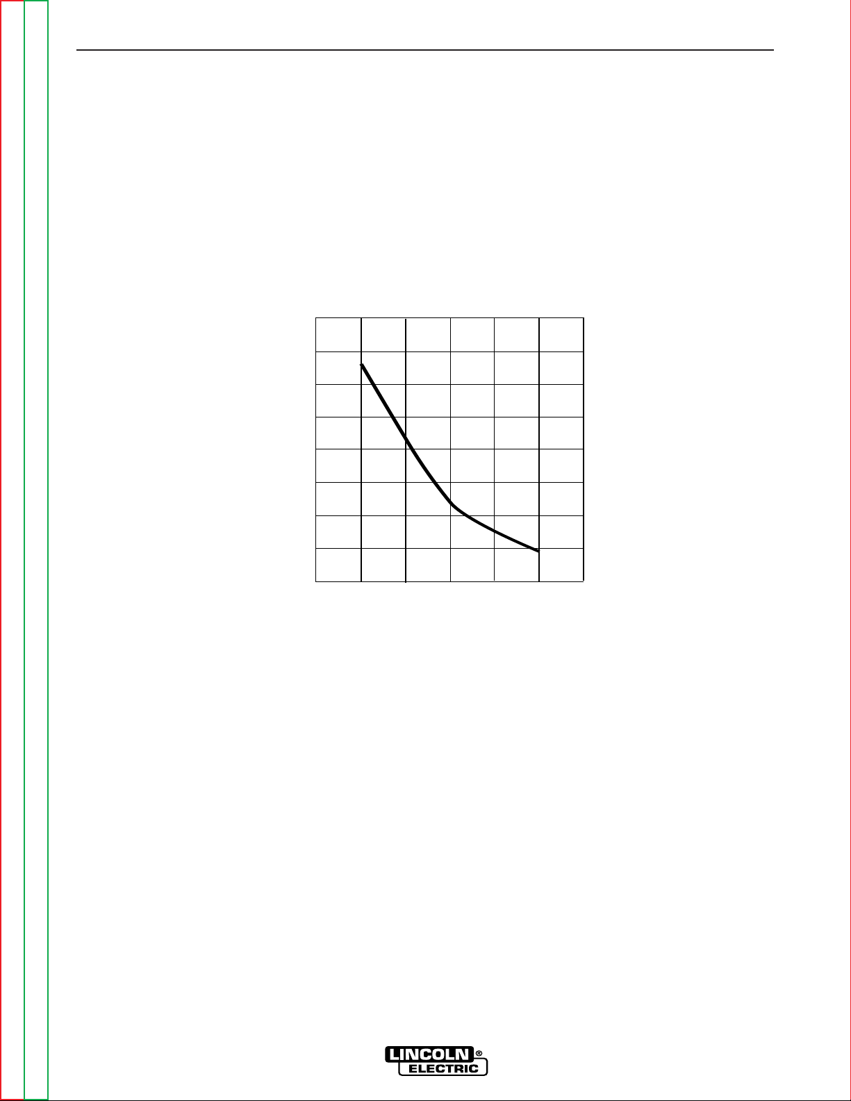
CUTTING CAPABILITY
The PRO-CUT 25 is rated at 25 amps, at 35% duty cycle on a 10 minute basis. If the duty cycle is exceeded, a
thermal protector will shut off the output of the machine until it cools to the normal operating temperature.
Figure B.1 shows the cut capacity of the PRO-CUT 25 when cutting mild steel. (The graph plots cut thickness vs.
torch travel speed with a torch standoff of 0.15".)
Lincoln's PRO-CUT 25
Cut Capacity Chart
Recommended Torch T ra vel Speed (IPM)
80% of Maximum Speed
80
60
40
20
0
0.3750.125
0.250
Metal Thickness (Inches)
Figure B.1
CONSUMABLE LIFE
The expected life for the PRO-CUT 25's electrode under normal operating conditions is approximately 1000
starts/cuts. An erosion of .060" is typical for end of electrode life, however, the electrode life may last longer. A
green and erratic arc will indicate definite electrode failure and the electrode should be replaced immediately.
It is recommended that consumables be replaced in complete sets. (Example: Electrode and Nozzle). This will
maximize the performance of the PRO-CUT 25 system.
Return to Section TOC Return to Section TOC Return to Section TOC Return to Section TOC
Return to Master TOC Return to Master TOC Return to Master TOC Return to Master TOC
OPERATION
B-5 B-5
PRO-CUT 25
LIMITATIONS
Do not exceed output current and duty cycle rating of
machine. Do not use the PRO-CUT 25 for pipe thaw-
ing.
CONTROLS AND SETTINGS
When preparing to cut, position the machine as close
to the work as possible. Make sure you have all mate-
rials needed to complete the job and have taken all
safety precautions. It is important to follow these oper-
ating steps each time you use the machine.
• Turn the machine's ON/OFF POWER SWITCH to
OFF position.
• Connect the air supply to the machine.
• Turn the main power and the machine power switch
on.
- The fan should start.
- The pre-charge circuit will operate for 3 seconds,
then the green "Power" LED should turn on.
• Be sure that the work lead is clamped to the work-
piece before cutting.
• Set the output current control knob at maximum
1
position for higher cutting speed and less dross for-
mation. Reduce the current, if desired to reduce the
kerf (cut) width, heat affected zone or travel speed
as required.
1
Maximum output requires a 30 amp input circuit and breaker. Refer to the
Technical Specifications for proper input circuit guidelines.
PRESSURE REGULATOR
CAP
• Push-in and hold the Purge button to check or set
the gas pressure. Pull the pressure regulator cap out
and turn it to set the pressure.
- Adjust the gas regulator for 65 PSI for 15’ or 25’
torches.
- Release the Purge button.
- The gas will immediately turn off. The pressure
gage may show an increase in pressure after the
air turns off but this is normal. Do NOT reset the
pressure while the air is NOT flowing.
• When ready to cut, place the torch near the work,
make certain all safety precautions have been taken
and pull the trigger.
- The air will flow for a preflow time of 2 seconds
and the pilot arc will start. (Exceptions: the first
time that the trigger is pulled after the machine is
turned on, or after a thermal tripout, will be
ignored. This is a safety feature to prevent the
pilot arc from firing unexpectedly or if the torch
button is pressed because it is laying up against
something. The other exception is if the machine
is in postflow, then the preflow time is skipped
and the pilot arc will start immediately.)
- The pilot arc will run for 3.0 seconds and shut off
unless the arc is brought in contact with the work
and the arc is transferred. Avoid excessive pilot
arc time by transferring the arc to the workpiece
quickly.
- When the arc is brought within 1/8” - 1/4" from
the work piece: the arc will transfer, the current
will ramp to the setting on the control panel, and
the cut can last indefinitely (or until the duty
cycle of the Pro-Cut is exceeded).
• Pierce the work piece by slowly lowering the torch
onto the metal at a 30
0
angle away from the operator.
This will blow the dross away from the torch tip.
Slowly rotate the torch to vertical position as the arc
becomes deeper.
• Keep moving while cutting. Cut at a steady speed
without pausing. Maintain the cutting speed so that
the arc leg is 10° to 20° behind the travel direction.
30
30
0
0
VER
VER
TICAL
ANGLE
TICAL ANGLE
FOR CUTTING
FOR CUTTING
CUT
90
0
TORCH AT 30
0
ANGLE
TO PIERCE
ROTATE TO
90
0
ANGLE TO CUT

OPERATION
B-6 B-6
PRO-CUT 25
Return to Section TOC Return to Section TOC Return to Section TOC Return to Section TOC
Return to Master TOC Return to Master TOC Return to Master TOC Return to Master TOC
Direction of Travel
5° - 15°
10° - 20°
Arc Lag
Leading Angle
•
Use a 5° - 15° leading angle in the direction of the cut.
• Finish the cut to be made and release the trigger.
• When the trigger is released, the arc will stop.
- The gas will continue to flow for 10 seconds of
postflow. If the trigger is activated within this time
period, the pilot arc will immediately restart.
• If the dross is difficult to remove, reduce the cutting
speed. High speed dross is more difficult to remove
than low speed dross.
• The right side of the cut is more square than the left
as viewed along the direction of travel.
• Clean spatter and scale from the nozzle frequently.
• If the "SAFETY" LED lights at any time; check the
following:
• Check the assembly of the torch consumables. If
they are not properly in place, the machine will not
start. Make sure that the shield cup is hand
tight. Do not use pliers or over tighten.
• Check the conditions of the inside of the nozzle. If
debris has collected, rub the electrode on the
inside bottom of the nozzle to remove any oxide
layer that may have built up. Refer to
"Suggestions for Extra Utility from the PRO-CUT
system".
• Check the condition of the electrode. If the end
has a crater-like appearance, replace it along with
the nozzle. The maximum wear depth of the elec-
trode is approximately .062”. A green and erratic
arc will indicate definite electrode failure and the
electrode should be replaced immediately.
• Replace the nozzle when the orifice exit is eroded
away or oval shaped.
• After the problem is found, or if there is nothing
apparently wrong, reset the machine by turning the
power switch OFF and then ON again. (It is possi-
ble for electrical noise to trip the safety circuit on rare
occasions. This should not be a regular occurrence.)
• If the machine does not reset or continues to trip,
consult the Troubleshooting Section.
• Use the proper cutting procedures referred to in
Procedure Recommendations.
PILOT ARC DISCUSSION
The PRO-CUT has a smooth, continuous pilot arc.
The pilot arc is only a means of transferring the arc to
the workpiece for cutting. Repeated pilot arc starts, in
rapid succession, is not recommended as these starts
will generally reduce consumable life. Occasionally,
the pilot arc may sputter or start intermittently. This is
aggravated when the consumables are worn or the air
pressure is too high. Always keep in mind that the pilot
arc is designed to transfer the arc to the workpiece and
not for numerous starts without cutting.
When the pilot arc is started, a slight impulse will be felt
in the torch handle. This occurrence is normal and is
the mechanism which starts the plasma arc. This
impulse can also be used to help troubleshoot a "no
start" condition.
ELECTRIC SHOCK CAN KILL.
• Turn off machine at the disconnect
switch on the front of the machine
before tightening, cleaning or replacing
consumables.
----------------------------------------------------------------------------
WARNING
OPERATION
B-7 B-7
PRO-CUT 25
Return to Section TOC Return to Section TOC Return to Section TOC Return to Section TOC
Return to Master TOC Return to Master TOC Return to Master TOC Return to Master TOC
PROCEDURE RECOMMENDATIONS
When properly used, plasma arc cutting is a very eco-
nomical process. Improper use will result in a very high
operating cost.
General - In All Cases
• Follow safety precautions as printed throughout
this operating manual and on the machine.
• If piercing is required, slowly lower the torch at
an angle of about 30° to blow the dross away
from the torch tip and slowly rotate the torch to
a vertical position as the arc becomes deeper.
This process will blow a lot of molten metal and
dross. Be careful! Blow the dross away from
the torch, the operator and any flammable
objects.
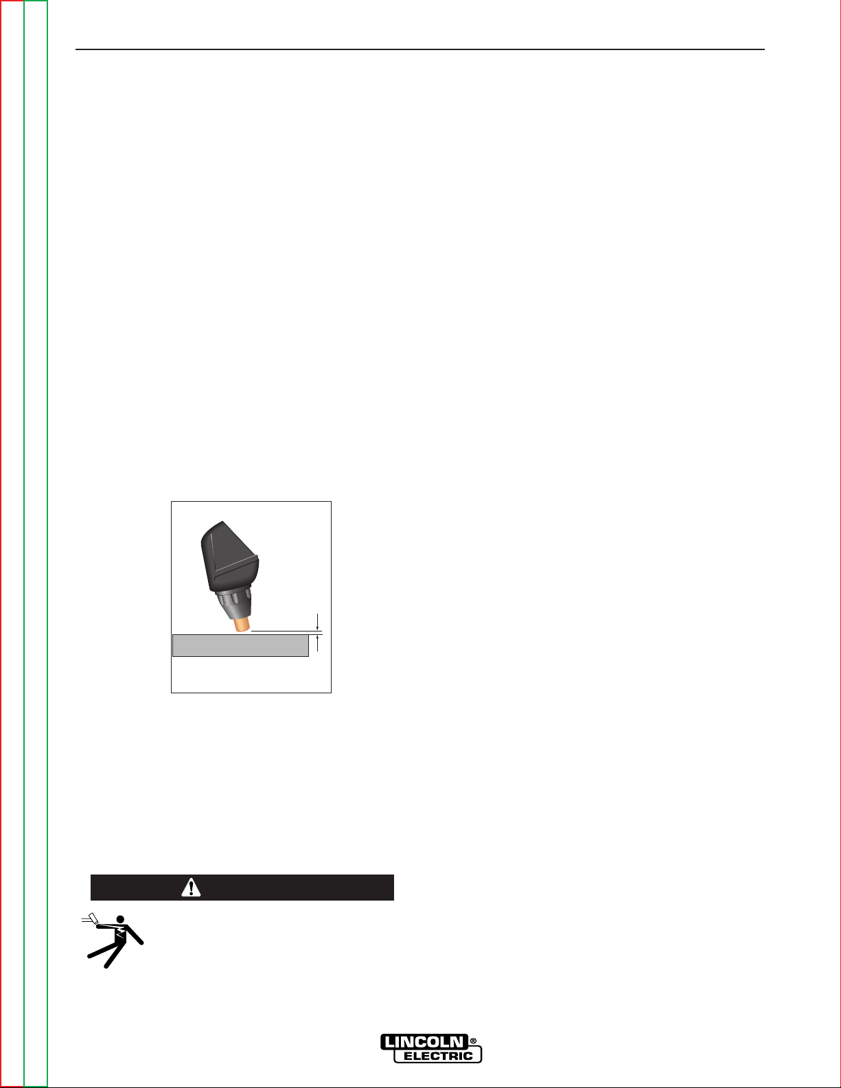
• The nozzle may be dragged on the metal sur-
face, touching it lightly to the surface. NOTE:
The use of a drag cup with the PRO-CUT is
not recommended. The increased standoff
distance reduces the overall performance of
the PRO-CUT.
• Where possible, start the cut from the edge of
the work piece.
• Keep moving! Asteady speed is necessary . Do
not pause.
Suggestions for Extra Utility from the
PRO-CUT System:
1. Occasionally an oxide layer may form over the tip of
the electrode, creating an insulating barrier
between the electrode and nozzle. This will result in
the tripping of the Pro-Cut's safety circuit. When
this happens turn the power off, remove the nozzle
and electrode and use the electrode to rub against
the inside bottom surface of the nozzle. This will
help remove any oxide buildup. Replace the noz-
zle, turn on the power and continue cutting. If the
safety circuit continues to trip after cleaning the
consumables, then replace them with a new set.
Do not continue to try and cut with excessively worn
consumables as this can cause damage to the
torch head and will degrade cut quality. Do not
allow torch cable or body to contact hot surface.
2. To improve consumable life, here are some sug-
gestions that may be useful:
a. Make sure the air supply to the Pro-Cut is
clean and free of oil. Use several extra in line
filters if necessary.
b. Minimize dross buildup on the nozzle tip by
starting the cut from the edge of the plate when
possible.
c. Pierce cutting should be done only when nec-
essary. If piercing, angle torch about 30° from
the plane perpendicular to the work piece,
transfer the arc, then bring the torch perpen-
dicular to the work and begin parallel move-
ment.
d. Reduce the number of pilot arc starts without
transferring to the work.
e. Reduce the pilot arc time before transferring to
the work.
f. Set air pressure to recommended setting. A
higher or lower pressure will cause turbulence
in the plasma arc, eroding the orifice of the
nozzle tip.
g. Use only Lincoln consumable parts. These
parts are patented and using any other
replacement consumables may cause damage
to the torch or reduce cut quality.
Torch Standoff
DRAG thru 1/16"
Standoff
DRAG thru 1/16”
Standoff
ELECTRIC SHOCK CAN KILL.
• Turn off machine at the disconnect
switch on the front of the machine
before tightening, cleaning or replacing
consumables.
----------------------------------------------------------------------------
WARNING

NOTES
B-8 B-8
PRO-CUT 25
Return to Section TOC Return to Section TOC Return to Section TOC Return to Section TOC
Return to Master TOC Return to Master TOC Return to Master TOC Return to Master TOC

TABLE OF CONTENTS
- ACCESSORIES -
Accessories...........................................................................................................................Section C
Options/Accessories...................................................................................................................C-2
Section C-1 Section C-1
PRO-CUT 25
Return to Master TOC Return to Master TOC Return to Master TOC Return to Master TOC
ACCESSORIES
C-2 C-2
PRO-CUT 25
Return to Section TOC Return to Section TOC Return to Section TOC Return to Section TOC
Return to Master TOC Return to Master TOC Return to Master TOC Return to Master TOC
ALW
AYS USE GENUINE LINCOLN
ELECTRIC ELECTRODES AND
VORTECH™
NOZZLES
• Only Genuine Lincoln Electric consumables yield the
best cutting performance for the PRO-CUT 25.
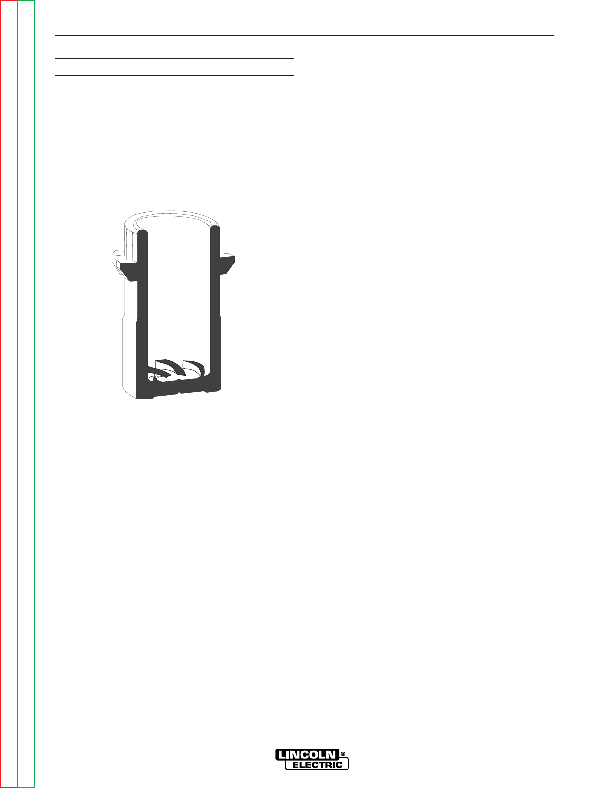
• The patented VORTECH™ nozzle provides an
extra “kick” of swirl as the arc exits the nozzle which
improves cutting performance. No other nozzle has
this capability or can match its performance.
GENERAL OPTIONS /
ACCESSORIES
The following options/accessories are available for
your PRO-CUT 25 from your local Lincoln Distributor.
S22147-028 - VORTECH™ nozzle with an .028” (0.7
mm) Orifice
S22149 - Electrode - replacement electrodes for cut-
ting.
S22150 - Shield Cup - This shields the nozzle and pro-
vides more visibility to the workpiece. Note the shield
cup does not prevent the torch tip from touching the
workpiece.
K1615 Series - PCT 20 Torches come in 15’ and 25’
lengths. Refer to the Parts Pages in the rear of this
manual for Torch parts.

Section D-1 Section D-1
PRO-CUT 25
TABLE OF CONTENTS
-MAINTENANCE-
Maintenance .........................................................................................................................Section D
Routine Maintenance..................................................................................................................D-2
Periodic Maintenance .................................................................................................................D-2
Thermal Protection .....................................................................................................................D-2
Replacement Of Internal Fuse....................................................................................................D-2
Major Component Locations .....................................................................................................D-3
Return to Master TOC Return to Master TOC Return to Master TOC Return to Master TOC

MAINTENANCE
D-2 D-2
PRO-CUT 25
Return to Section TOC Return to Section TOC Return to Section TOC Return to Section TOC
Return to Master TOC Return to Master TOC Return to Master TOC Return to Master TOC
PERIODIC MAINTENANCE
Change consumables as required.
THERMAL PROTECTION
Thermal Detection Devices protect the machine from
excessive operating temperatures. Excessive temper-
atures may be caused by a lack of cooling air or oper-
ating the machine beyond the duty cycle and output
rating. If excessive operating temperatures should
occur, the yellow thermal LED will light and the
Detection Devices will prevent output voltage or cur-
rent.
These Detection Devices are self-resetting once the
machine cools sufficiently. If the thermostat shutdown
was caused by excessive output or duty cycle and the
fan is operating normally , the Power Switch may be left
on and the reset should occur within a 15 minute peri-
od. If the fan is not turning or the air intake louvers
were obstructed, then the power must be switched off
and the fan problem or air obstruction must be correct-
ed.
A protection circuit is included to monitor the voltage
across filter capacitors. In the event that the capacitor
voltage is too high, the protection circuit will prevent
output.
REPLACEMENT OF INTERNAL FUSES
The PRO-CUT 25 has additional protection provided to
some circuits through internal fuses. For replacement
of those fuses proceed as follows:
1. Turn off the power to the unit and remove the input
plug.
2. Allow the machine to stand for 5 minutes to let the
input capacitors discharge.
3. Remove the machine cover.
4. Replace the blown fuse with a new 0.5A 500V
slowblow fuse or 32A 400V fuse as appropriate.
NOTE: If the fuse blows again after power is restored,
the cause could be an internal breakdown in
the power unit. In this case, take the unit to an
authorized Lincoln Field Service Shop.
ELECTRIC SHOCK can kill.
• Have an electrician install and service
this equipment.
• Turn the input power off at the fuse box
before working on equipment.
• Do not touch electrically hot parts.
• Prior to Performing preventative main-
tenance, perform the following capaci-
tor discharge procedure to avoid elec-
tric shock.
---------------------------------------------------------------------
ROUTINE MAINTENANCE
1. Keep the cutting or gouging area and the area
around the machine clean and free of combustible
materials. No debris should be allowed to collect
which could obstruct air flow to the machine.
2. Every 6 months or so, the machine should be
cleaned with a low pressure airstream. Keeping the
machine clean will result in cooler operation and
higher reliability. Be sure to clean these areas:
- Printed circuit boards and heat sinks
- Power switch
• When using a low pressure aistream, wear
appropiate eye protection.
------------------------------------------------------------------------
3. Examine the sheet metal case for dents or break-
age. Repair the case as required. Keep the case in
good condition to insure that high voltage parts are
protected and correct spacings are maintained. All
external sheet metal screws must be in place to
insure case strength and electrical ground continu-
ity.
4. Inspect the cable periodically for any slits or punc-
ture marks in the cable jacket. Replace if neces-
sary. Check to make sure that nothing is crushing
the cable and blocking the flow of air through the air
tube inside. Also, check for kinks in the cable peri-
odically and relieve any so as not to restrict the flow
of air to the torch.
WARNING
ELECTRIC SHOCK CAN KILL.
• Turn off machine at the disconnect
switch on the front of the machine
before tightening, cleaning or replacing
consumables.
----------------------------------------------------------------------------
WARNING
CAUTION
L
IN
C
O
L
N
E
L
E
C
T
R
IC
PRO-CUT 25
O
N
O
F
F
P
U
R
G
E
POWER
GAS PRESSURE
THERMAL
SAFETY
!
R
E
Q
U
I
R
E
S
2
0
A
/
1
1
5
V
B
R
A
N
C
H
C
I
R
C
U
I
T
R
E
Q
U
I
R
E
S
3
0
A
/
1
1
5
V
B
R
A
N
C
H
C
I
R
C
U
I
T
2
5
2
0
P
C
T
2
0
6
1
2
4
3
5
7
MAINTENANCE
D-3 D-3
PRO-CUT 25
Return to Section TOC Return to Section TOC Return to Section TOC Return to Section TOC
Return to Master TOC Return to Master TOC Return to Master TOC Return to Master TOC
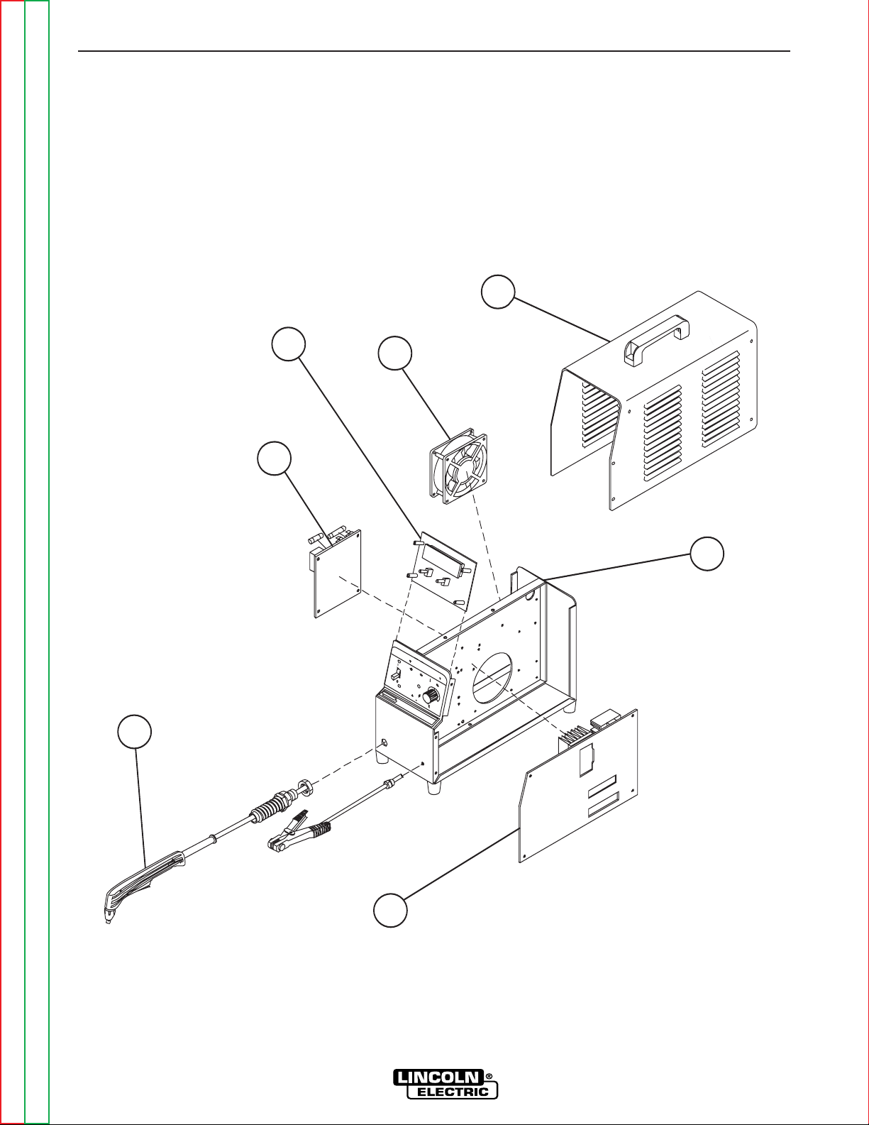
FIGURE D.2 – MAJOR COMPONENT LOCATIONS
1. Central Metal Wall
2. Main Board
3. Input Board
4. Control Board
5. Fan
6. Case Wraparound
7. Torch

NOTES
D-4 D-4
PRO-CUT 25
Return to Section TOC Return to Section TOC Return to Section TOC Return to Section TOC
Return to Master TOC Return to Master TOC Return to Master TOC Return to Master TOC
Section E-1 Section E-1
PRO-CUT 25
Theory of Operation .............................................................................................................Section E
General Description ....................................................................................................................E-2
Input Line Voltage and Auxiliary Transformer .............................................................................E-2
Precharge and Protection ...........................................................................................................E-3
Main Transformer ........................................................................................................................E-4
Output Section and Torch...........................................................................................................E-5
Control Board .............................................................................................................................E-6
Protection Circuits ......................................................................................................................E-7
Overload Protection..............................................................................................................E-7
Thermal Protection ...............................................................................................................E-7
Accidental Operation Protection.................................................................................................E-7
Safety Parts-In-Place Protection ................................................................................................E-7
Insulated Gate Bipolar Transistor (IGBT) Operation ...................................................................E-8
TABLE OF CONTENTS
-THEORY OF OPERATION SECTION-
115/230/1/50/60 VAC
INPUT
CN1
2
1
4
3
5
6
7
8
300uH
L1
RL3
10/10W
R1
V2
V1
B
A
1A/250V
F1
RL2
RL2
RL2
AC
CP
CP
AC
L1
RL1
RL2
115VAC
230V
T1
115V
RL1
L1
15VAC
15VAC
SAFETY
+28VDC
SEC GND
OVLOAD
115/230
+12VDC
AC
CP
CP
AC
CN2
6
9
10
2
20
15 16
+15Vrms
EV1
NO
COM
NC
12VDC
PS2
PS1
861793
OVLOAD
SEC GND
SAFETY
CN1
12 18 14 1 11 4 13 7 19 24 21 23 8 1 2 3
3
22
17
V+
+12VDC
+12VDC_SW
+8V_SW
SEC GND
OVLOAD
TRANSFER SW
TRANSFER
SOL 1 DRIVER
SOL 2 DRIVER
TRIGGER
OUTPUT
V_OUT
121814 7 15 4 11 5 16 10 12 13
5
4
POT_WIPER
23
POT_CW
22
POT_CCW
24
CP
15K/3W
R1
15K/3W
R2
1500uF/250V
C2a,b
1500uF/250V
C1a,b
C12
CP
C26
IRG4BC30W
Q1a,b,c
IRG4BC30W
Q2a,b,c
SEC
PRI
T2
C13
D10
D11
240uH
Lout
SHUNT
SH-
SH+
BS1
8A
+12VDC
TRANSFER
C14
6.8k/5W
R24
WRK
NZL (2)
EL (3)
CN3
2
1
3
4
12VDC
PT
WORK CLAMP
CN1
SW1
230VAC
FN1
+
+
RL1
Display LED's
Control Board
Output Control
Air
Solenoid
1
Purge
Switch
Input
Voltage Board
Main Inverter Board
Solenoid 2
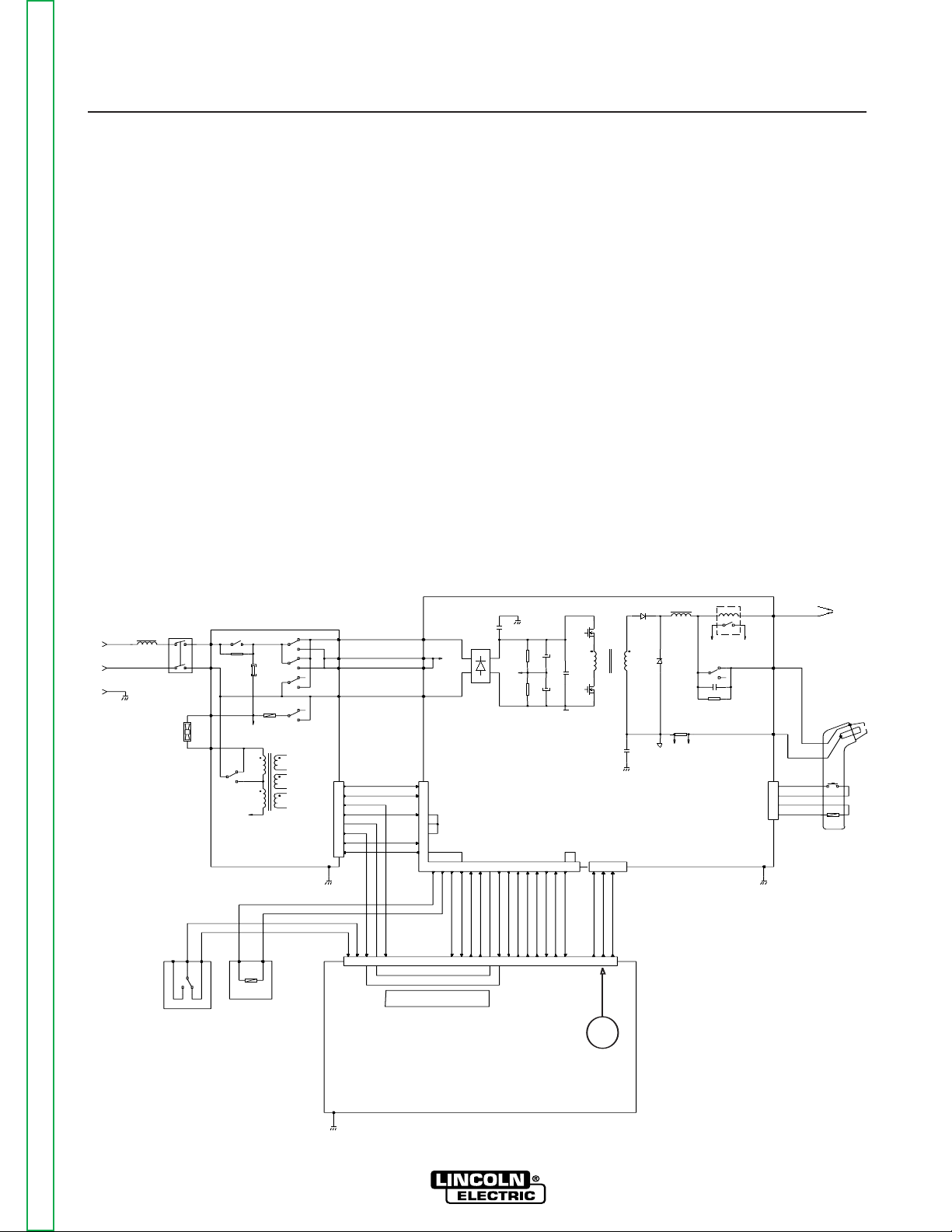
FIGURE E.1 – PRO-CUT 25 BLOCK LOGIC DIAGRAM
Return to Master TOC Return to Master TOC Return to Master TOC Return to Master TOC
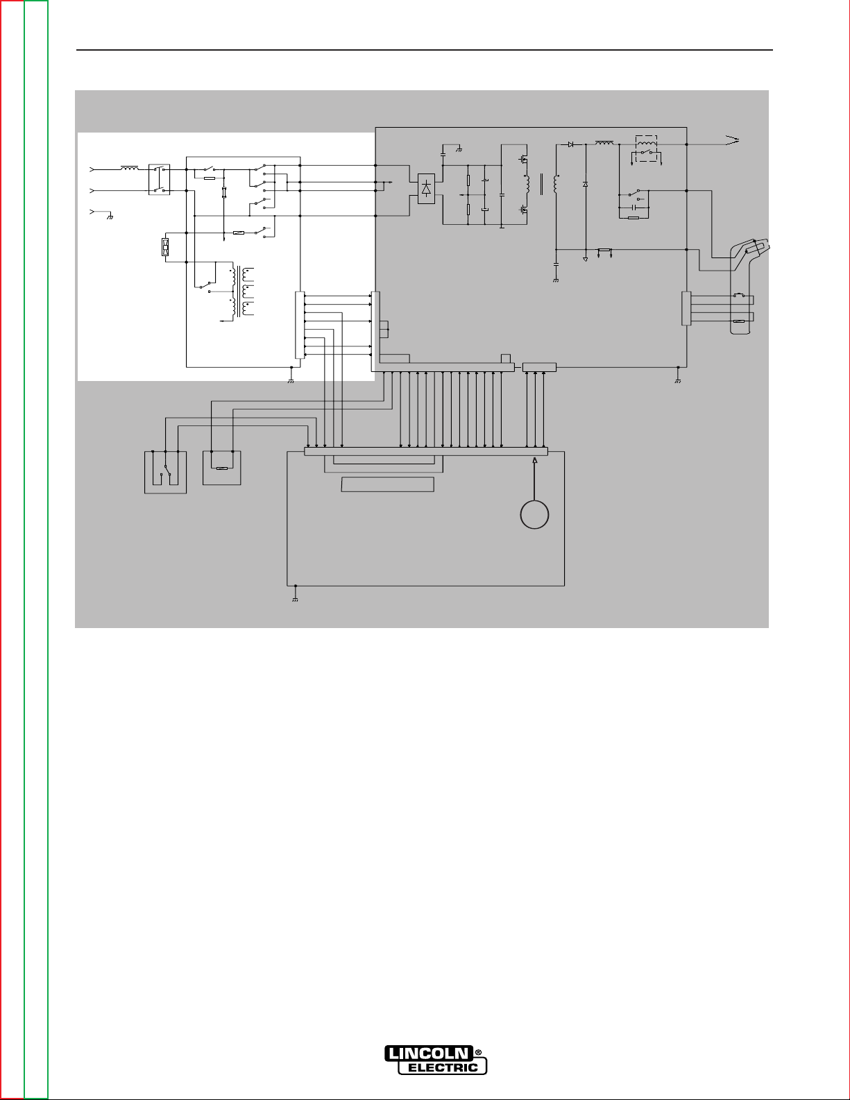
FIGURE E.2 – INPUT LINE VOLTAGE
GENERAL DESCRIPTION
The PRO-CUT 25 is an inverter based constant
current, continuous control plasma cutting power
source. The control system has a safety mechanism
to insure that the nozzle and electrode are in place
before cutting or gouging. The PRO-CUT 25 initiates
the plasma arc with a simple, yet reliable, touch start
mechanism. This system eliminates many of the prob-
lems associated with hi-frequency type start systems.
INPUT LINE VOLTAGE, AND
AUXILIARY TRANSFORMER
The single-phase input power of 115 230 Volts AC is
connected to the machine, via an input cord, to a
switch located on the front panel.
The PRO-CUT 25 Input voltage board automatically
reconnects the auxiliary and inverter connections to
configure the machine for either a low 115V AC or high
230V AC input voltage. The auxiliary transformer
develops the appropriate AC voltages to operate the
cooling fan, the control board, and the inverter board.
THEORY OF OPERATION
E-2 E-2
PRO-CUT 25
Return to Section TOC Return to Section TOC Return to Section TOC Return to Section TOC
Return to Master TOC Return to Master TOC Return to Master TOC Return to Master TOC
NOTE: Unshaded areas of Block Logic Diagram are the subject of discussion.
115/230/1/50/60 VAC
INPUT
CN1
2
1
4
3
5
6
7
8
300uH
L1
RL3
10/10W
R1
V2
V1
B
A
1A/250V
F1
RL2
RL2
RL2
AC
CP
CP
AC
L1
RL1
RL2
115VAC
230V
T1
115V
RL1
L1
15VAC
15VAC
SAFETY
+28VDC
SEC GND
OVLOAD
115/230
+12VDC
AC
CP
CP
AC
CN2
6
9
10
2
20
15 16
+15Vrms
EV1
NO
COM
NC
12VDC
PS2
PS1
861793
OVLOAD
SEC GND
SAFETY
CN1
12 18 14 1 11 4 13 7 19 24 21 23 8 1 2 3
3
22
17
V+
+12VDC
+12VDC_SW
+8V_SW
SEC GND
OVLOAD
TRANSFER SW
TRANSFER
SOL 1 DRIVER
SOL 2 DRIVER
TRIGGER
OUTPUT
V_OUT
121814 7 15 4 11 5 16 10 12 13
5
4
POT_WIPER
23
POT_CW
22
POT_CCW
24
CP
15K/3W
R1
15K/3W
R2
1500uF/250V
C2a,b
1500uF/250V
C1a,b
C12
CP
C26
IRG4BC30W
Q1a,b,c
IRG4BC30W
Q2a,b,c
SEC
PRI
T2
C13
D10
D11
240uH
Lout
SHUNT
SH-
SH+
BS1
8A
+12VDC
TRANSFER
C14
6.8k/5W
R24
WRK
NZL (2)
EL (3)
CN3
2
1
3
4
12VDC
PT
WORK CLAMP
CN1
SW1
230VAC
FN1
+
+
RL1
Display LED's
Control Board
Output Control
Air
Solenoid
1
Purge
Switch
Input
Voltage Board
Main Inverter Board
Solenoid 2
 Loading...