


R3R-300

IM409-E
RETURN TO MAIN MENU
IDEALARC
Safety Depends on You
Lincoln arc welding and cutting
equipment is designed and built
with safety in mind. However,
your overall safety can be
increased by proper installation
... and thoughtful operation on
your part. DO NOT INSTALL,
OPERATE OR REPAIR THIS
EQUIPMENT WITHOUT READING THIS MANUAL AND THE
SAFETY PRECAUTIONS CONTAINED THROUGHOUT. And,
most importantly,think before you
act and be careful.
®
For use with machine Code Numbers:
November, 2009
R3R-300, -400 AND -500
9534 thru 10471,
10857, 10858, 10881, 10882,
11043, 11044, 11045, 11046
11342, 11344
Cleveland, Ohio 44117-1199 U.S.A. TEL: 216.481.8100 FAX: 216.486.1751 WEB SITE: www.lincolnelectric.com
OPERATOR’S MANUAL
Copyright © Lincoln Global Inc.
• World's Leader in Welding and Cutting Products •
• Sales and Service through Subsidiaries and Distributors Worldwide •
i
SAFETY
WARNING
CALIFORNIA PROPOSITION 65 WARNINGS
Diesel engine exhaust and some of its constituents
are known to the State of California to cause cancer, birth defects, and other reproductive harm.
The Above For Diesel Engines
ARC WELDING CAN BE HAZARDOUS. PROTECT YOURSELF AND OTHERS FROM POSSIBLE SERIOUS INJURY OR DEATH.
KEEP CHILDREN AWAY. PACEMAKER WEARERS SHOULD CONSULT WITH THEIR DOCTOR BEFORE OPERATING.
Read and understand the following safety highlights. For additional safety information, it is strongly recommended that you
purchase a copyof “Safety in Welding & Cutting - ANSI Standard Z49.1” from theAmerican WeldingSociety, P.O. Box 351040,
Miami, Florida 33135 or CSA Standard W117.2-1974. AFree copy of “Arc Welding Safety” booklet E205 is available from the
Lincoln Electric Company, 22801 St. Clair Avenue, Cleveland, Ohio 44117-1199.
BE SURE THAT ALL INSTALLATION, OPERATION, MAINTENANCE AND REPAIR PROCEDURES ARE
PERFORMED ONLY BY QUALIFIED INDIVIDUALS.
The engine exhaust from this product contains
chemicals known to the State of California to cause
cancer, birth defects, or other reproductive harm.
The Above For Gasoline Engines
i
FOR ENGINE
powered equipment.
1.a. Turn the engine off before troubleshooting and maintenance
work unless the maintenance work requires it to be running.
____________________________________________________
1.b.Operate engines in open, well-ventilated
areas or vent the engine exhaust fumes
outdoors.
____________________________________________________
1.c. Do not add the fuel near an open flame weld-
ing arc or when the engine is running. Stop
the engine and allow it to cool before refueling to prevent spilled fuel from vaporizing on
contact with hot engine parts and igniting. Do
not spill fuelwhen filling tank. If fuel is spilled,
wipe it up and do not start engine until fumes
have been eliminated.
____________________________________________________
1.d. Keep all equipment safety guards, covers
and devices in position and in good
repair.Keep hands, hair, clothing and tools
away from V-belts, gears, fans and all other
moving parts when starting, operating or
repairing equipment.
____________________________________________________
1.e. In some cases it may be necessary to remove safety
guards to perform required maintenance. Remove
guards only when necessary and replace them when the
maintenance requiring their removal is complete.
Always use the greatest care when working near moving
parts.
___________________________________________________
1.f. Do notput your handsnear the enginefan. Do not attempt to
override the governor or idler by pushing on the throttle control rods while the engine is running.
___________________________________________________
1.g. To prevent accidentally starting gasoline engines while
turning the engine or welding generator during maintenance
work, disconnect the spark plug wires, distributor cap or
magneto wire as appropriate.
1.h. To avoid scalding, do not remove the
radiator pressure cap when the engine is
hot.
ELECTRIC AND
MAGNETIC FIELDS
may be dangerous
2.a. Electric current flowing through any conductor causes
localized Electric and Magnetic Fields (EMF). Welding
current creates EMF fields around welding cables and
welding machines
2.b. EMF fields may interfere with some pacemakers, and
welders having a pacemaker should consult their physician
before welding.
2.c. Exposure to EMF fields in welding may have other health
effects which are now not known.
2.d. All welders should use the following procedures in order to
minimize exposure to EMF fields from the welding circuit:
2.d.1.
Route the electrode and work cables together - Secure
them with tape when possible.
2.d.2. Never coil the electrode lead around your body.
2.d.3. Do not place your body between the electrode and
work cables. If the electrode cable is on your right
side, the work cable should also be on your right side.
2.d.4. Connect the work cable to the workpiece as close as
possible to the area being welded.
2.d.5. Do not work next to welding power source.
Mar ‘95
ii
SAFETY
ii
ELECTRIC SHOCK can kill.
3.a. The electrode and work (or ground) circuits
are electrically “hot” when the welder is on.
Do not touch these “hot” parts with your bare
skin or wet clothing. Wear dry, hole-free
gloves to insulate hands.
3.b. Insulate yourself from work and ground using dry insulation.
Make certain the insulation is large enough to cover your full
area of physical contact with work and ground.
In addition to the normal safety precautions, if welding
must be performed under electrically hazardous
conditions (in damp locations or while wearing wet
clothing; on metal structures such as floors, gratings or
scaffolds; when in cramped positions such as sitting,
kneeling or lying, if there is a high risk of unavoidable or
accidental contact with the workpiece or ground) use
the following equipment:
• Semiautomatic DC Constant Voltage (Wire) Welder.
• DC Manual (Stick) Welder.
• AC Welder with Reduced Voltage Control.
3.c. In semiautomatic or automatic wire welding, the electrode,
electrode reel, welding head, nozzle or semiautomatic
welding gun are also electrically “hot”.
3.d. Always be sure the work cable makes a good electrical
connection with the metal being welded. The connection
should be as close as possible to the area being welded.
3.e. Ground the work or metal to be welded to a good electrical
(earth) ground.
3.f.
Maintain the electrode holder, work clamp, welding cable and
welding machine in good, safe operating condition. Replace
damaged insulation.
3.g. Never dip the electrode in water for cooling.
3.h. Never simultaneously touch electrically “hot” par ts of
electrode holders connected to two welders because voltage
between the two can be the total of the open circuit voltage
of both welders.
3.i. When working above floor level, use a safety belt to protect
yourself from a fall should you get a shock.
3.j. Also see Items 6.c. and 8.
ARC RAYS can burn.
4.a. Use a shield with the proper filter and cover
plates to protect your eyes from sparks and
the rays of the arc when welding or observing
open arc welding. Headshield and filter lens
should conform to ANSI Z87. I standards.
4.b. Use suitable clothing made from durable flame-resistant
material to protect your skin and that of your helpers from
the arc rays.
4.c. Protect other nearby personnel with suitable, non-flammable
screening and/or warn them not to watch the arc nor expose
themselves to the arc rays or to hot spatter or metal.
FUMES AND GASES
can be dangerous.
5.a. Welding may produce fumes and gases
hazardous to health. Avoid breathing these
fumes and gases. When welding, keep
your head out of the fume. Use enough
ventilation and/or exhaust at the arc to keep
fumes and gases away from the breathing zone. When
welding with electrodes which require special
ventilation such as stainless or hard facing (see
instructions on container or MSDS) or on lead or
cadmium plated steel and other metals or coatings
which produce highly toxic fumes, keep exposure as
low as possible and within applicable OSHA PEL and
ACGIH TLV limits using local exhaust or mechanical ventilation. In confined spaces or in some circumstances,
outdoors, a respirator may be required. Additional precautions are also required when welding on galvanized
steel.
5. b. The operation of welding fume control equipment is affected
by various factors including proper use and positioning of the
equipment, maintenance of the equipment and the specific
welding procedure and application involved. Worker exposure level should be checked upon installation and periodically thereafter to be certain it is within applicable OSHA PEL
and ACGIH TLV limits.
5.c.
Do not weld in locations near chlorinated hydrocarbon
coming from degreasing, cleaning or spraying operations.
The heat and rays of the arc can react with solvent vapors
form phosgene, a highly toxic gas, and other irritating products.
vapors
to
5.d. Shielding gases used for arc welding can displace air and
cause injury or death. Always use enough ventilation,
especially in confined areas, to insure breathing air is safe.
5.e. Read and understand the manufacturer’s instructions for this
equipment and the consumables to be used, including the
material safety data sheet (MSDS) and follow your
employer’s safety practices. MSDS forms are available from
your welding distributor or from the manufacturer.
5.f. Also see item 1.b.
Jan ‘09
iii
SAFETY
iii
WELDING and CUTTING
SPARKS can
cause fire or explosion.
6.a.
Remove fire hazards from the welding area.
If this is not possible, cover them to prevent
Remember that welding sparks and hot
materials from welding can easily go through small cracks
and openings to adjacent areas. Avoid welding near
hydraulic lines. Have a fire extinguisher readily available.
6.b. Where compressed gases are to be used at the job site,
special precautions should be used to prevent hazardous
situations. Refer to “Safety in Welding and Cutting” (ANSI
Standard Z49.1) and the operating information for the
equipment being used.
6.c. When not welding, make certain no part of the electrode
circuit is touching the work or ground.Accidental contact can
cause overheating and create a fire hazard.
6.d. Do not heat, cut or weld tanks, drums or containers until the
proper steps have been taken to insure that such procedures
will not cause flammable or toxic vapors from substances
inside. They can cause an explosion even
been “cleaned”. For information, purchase “Recommended
Safe Practices for the
Containers and Piping That Have Held Hazardous
Substances”, AWS F4.1 from the American Welding Society
(see address above).
6.e. Vent hollow castings or containers before heating, cutting or
welding. They may explode.
Sparks and spatter are thrown from the welding arc. Wear oil
6.f.
free protective garments such as leather gloves, heavy shirt,
cuffless trousers, high shoes and a cap over your hair. Wear
ear plugs when welding out of position or in confined places.
Always wear safety glasses with side shields when in a
welding area.
6.g. Connect the work cable to the work as close to the welding
area as practical. Work cables connected to the building
framework or other locations away from the welding area
increase the possibility of the welding current passing
through lifting chains, crane cables or other alternate circuits.
This can create fire hazards or overheat lifting chains or
cables until they fail.
6.h. Also see item 1.c.
the welding sparks from starting a fire.
though
they have
Preparation
for Welding and Cutting of
CYLINDER may explode
if damaged.
7.a. Use only compressed gas cylinders
containing the correct shielding gas for the
process used and properly operating
regulators designed for the gas and
pressure used. All hoses, fittings, etc. should be suitable for
the application and maintained in good condition.
7.b. Always keep cylinders in an upright position securely
chained to an undercarriage or fixed support.
7.c. Cylinders should be located:
• Away from areas where they may be struck or subjected to
physical damage.
• A safe distance from arc welding or cutting operations and
any other source of heat, sparks, or flame.
7.d. Never allow the electrode, electrode holder or any other
electrically “hot” parts to touch a cylinder.
7.e. Keep your head and face away from the cylinder valve outlet
when opening the cylinder valve.
7.f. Valve protection caps should always be in place and hand
tight except when the cylinder is in use or connected for
use.
7.g. Read and follow the instructions on compressed gas
cylinders, associated equipment, and CGA publication P-l,
“Precautions for Safe Handling of Compressed Gases in
Cylinders,” available from the Compressed Gas Association
1235 Jefferson Davis Highway, Arlington, VA 22202.
FOR ELECTRICALLY
powered equipment.
8.a. Turn off input power using the disconnect
switch at the fuse box before working on
the equipment.
8.b. Install equipment in accordance with the U.S. National
Electrical Code, all local codes and the manufacturer’s
recommendations.
8.c. Ground the equipment in accordance with the U.S. National
Electrical Code and the manufacturer’s recommendations.
6.I. Read and follow NFPA 51B “ Standard for Fire Prevention
During Welding, Cutting and Other Hot Work”, available from
NFPA, 1 Batterymarch Park, PO box 9101, Quincy, Ma
022690-9101.
6.j. Do not use a welding power source for pipe thawing.
Refer to http://www.lincolnelectric.com/safety for additional safety information.
Jan ‘09

iv
SAFETY
iv
PRÉCAUTIONS DE SÛRETÉ
Pour votre propre protection lireet observer toutes les instructions et
les précautions de sûreté specifiques qui parraissent dans ce
manuel aussi bien que les précautions de sûreté générales suivantes:
Sûreté Pour Soudage A L’Arc
1. Protegez-vous contre la secousse électrique:
a. Les circuits à l’électrode et à la piéce sont sous tension
quand la machine à souder est en marche. Eviter toujours
tout contact entre les parties sous tension et la peau nue ou
les vétements mouillés. Porter des gants secs et sans trous
pour isoler les mains.
b. Faire trés attention de bien s’isoler de la masse quand on
soude dans des endroits humides, ou sur un plancher metallique ou des grilles metalliques, principalement dans
les positions assis ou couché pour lesquelles une grande
partie du corps peut être en contact avec la masse.
c. Maintenir le porte-électrode, la pince de masse, le câble de
soudage et la machine à souder en bon et sûr état defonctionnement.
d.Ne jamais plonger le porte-électrode dans l’eau pour le
refroidir.
e. Ne jamais toucher simultanément les parties sous tension
des porte-électrodes connectés à deux machines à souder
parce que la tension entre les deux pinces peut être le total
de la tension à vide des deux machines.
f. Si on utilise la machine à souder comme une source de
courant pour soudage semi-automatique, ces precautions
pour le porte-électrode s’applicuent aussi au pistolet de
soudage.
6. Eloigner les matériaux inflammables ou les recouvrir afin de
prévenir tout risque d’incendie dû aux étincelles.
7. Quand onne soude pas, poser la pince à une endroit isolé de
la masse. Un court-circuit accidental peut provoquer un
échauffement et un risque d’incendie.
8. S’assurer que la masseest connectéeleplus prés possible de
la zone de travail qu’il est pratique de le faire. Si on place la
masse sur la charpentede la construction ou d’autresendroits
éloignés de la zone de travail, on augmente le risque de voir
passer le courant de soudage par les chaines de levage,
câbles de grue, ou autres circuits. Cela peut provoquer des
risques d’incendie ou d’echauffement des chaines et des
câbles jusqu’à ce qu’ils se rompent.
9. Assurer une ventilation suffisante dans la zone de soudage.
Ceci est particuliérement important pour le soudage de tôles
galvanisées plombées, ou cadmiées ou tout autre métal qui
produit des fumeés toxiques.
10. Ne pas souder en présence de vapeurs de chlore provenant
d’opérations de dégraissage, nettoyage ou pistolage. La
chaleur ou lesrayons de l’arc peuvent réagir avec lesvapeurs
du solvant pourproduire du phosgéne(gas fortement toxique)
ou autres produits irritants.
11.Pour obtenirde plus amples renseignementssur lasûreté, voir
le code “Codefor safety in welding and cutting” CSAStandard
W 117.2-1974.
2. Dans le cas de travail au dessus du niveau du sol, se protéger
contre les chutes dans le cas ou on recoit un choc. Ne jamais
enrouler le câble-électrode autour de n’importe quelle partie du
corps.
3. Un coup d’arc peut être plus sévère qu’un coup de soliel, donc:
a. Utiliser un bon masque avec un verre filtrant approprié ainsi
qu’un verre blanc afin de se protéger les yeux du rayonnement de l’arc etdes projectionsquand on soude ou quand
on regarde l’arc.
b. Porter des vêtements convenables afin de protéger la peau
de soudeur et des aides contre le rayonnement de l‘arc.
c. Protéger l’autrepersonnel travaillant àproximité au soudage
à l’aide d’écrans appropriés et non-inflammables.
4. Desgouttes de laitier en fusion sont émisesde l’arcde soudage.
Se protéger avec des vêtements de protection libres de l’huile,
tels que les gants en cuir, chemise épaisse, pantalons sans
revers, et chaussures montantes.
5. Toujours porter des lunettes de sécurité dans la zone de
soudage. Utiliser des lunettes avec écrans lateraux dans les
zones où l’on pique le laitier.
PRÉCAUTIONS DE SÛRETÉ POUR
LES MACHINES À SOUDER À
TRANSFORMATEUR ET À
REDRESSEUR
1. Relier à la terre le chassisdu poste conformement aucode de
l’électricité et aux recommendations du fabricant. Le dispositif
de montage ou la piece à souder doit être branché à une
bonne mise à la terre.
2. Autant que possible, I’installation et l’entretien du poste seront
effectués par un électricien qualifié.
3. Avant de fairesdes travaux à l’interieurde poste, la debrancher à l’interrupteur à la boite de fusibles.
4. Garder tous les couvercles et dispositifs de sûreté à leur
place.
Mar. ‘93

Thank You
vv
for selecting a QUALITY product by Lincoln Electric. We want you
to take pride in operating this Lincoln Electric Company product •••
as much pride as we have in bringing this product to you!
The business of The Lincoln Electric Company is manufacturing and selling high quality welding equipment, consumables, and cutting equipment. Our challenge is to meet the needs of our customers and to exceed their expectations. On occasion, purchasers may ask Lincoln Electric
for advice or information about their use of our products. We respond to our customers based on the best information in our possession at that
time. Lincoln Electric is not in a position to warrant or guarantee such advice, and assumes no liability, with respect to such information or
advice. We expressly disclaim any warranty of any kind, including any warranty of fitness for any customer’s particular purpose, with respect
to such information or advice. As a matter of practical consideration, we also cannot assume any responsibility for updating or correcting any
such information or advice once it has been given, nor does the provision of information or advice create, expand or alter any warranty with
respect to the sale of our products.
Lincoln Electric is a responsive manufacturer, but the selection and use of specific products sold by Lincoln Electric is solely within the control
of, and remains the sole responsibility of the customer. Many variables beyond the control of Lincoln Electric affect the results obtained in applying these types of fabrication methods and service requirements.
Subject to Change – This information is accurate to the best of our knowledge at the time of printing. Please refer to www.lincolnelectric.com
for any updated information.
CUSTOMER ASSISTANCE POLICY
Please Examine Carton and Equipment For Damage Immediately
When this equipment is shipped, title passes to the purchaser upon receipt by the carrier. Consequently, Claims
for material damaged in shipment must be made by the purchaser against the transportation company at the time
the shipment is received.
Please record your equipment identification information below for future reference. This information can be found
on your machine nameplate.
Product _________________________________________________________________________________
Model Number ___________________________________________________________________________
Code Number or Date Code_________________________________________________________________
Serial Number____________________________________________________________________________
Date Purchased___________________________________________________________________________
Where Purchased_________________________________________________________________________
Whenever you request replacement parts or information on this equipment, always supply the information you
have recorded above. The code number is especially important when identifying the correct replacement parts.
On-Line Product Registration
- Register your machine with Lincoln Electric either via fax or over the Internet.
• For faxing: Complete the form on the back of the warranty statement included in the literature packet
accompanying this machine and fax the form per the instructions printed on it.
• For On-Line Registration: Go to our
“Product Registration”. Please complete the form and submit your registration.
Read this Operators Manual completely before attempting to use this equipment. Save this manual and keep it
handy for quick reference. Pay particular attention to the safety instructions we have provided for your protection.
The level of seriousness to be applied to each is explained below:
WEB SITE at www.lincolnelectric.com. Choose “Quick Links” and then
WARNING
This statement appears where the information must be followed exactly to avoid serious personal injury or loss of life.
CAUTION
This statement appears where the information must be followed to avoid minor personal injury or damage to this equipment.

vi
TABLE OF CONTENTS
Page
____________________________________________________________________________
Installation . . . . . . . . . . . . . . . . . . . . . . . . . . . . . . . . . . . . . . . . . . . . . . . . . . . . . . . . . Section A
Location and Stacking . . . . . . . . . . . . . . . . . . . . . . . . . . . . . . . . . . . . . . . . . . . . . . . . . . . A-1
Input Wiring . . . . . . . . . . . . . . . . . . . . . . . . . . . . . . . . . . . . . . . . . . . . . . . . . . . . . . . . . . . A-1
Output Connections . . . . . . . . . . . . . . . . . . . . . . . . . . . . . . . . . . . . . . . . . . . . . . . . . . . . .A-2
____________________________________________________________________________
Operating Instructions . . . . . . . . . . . . . . . . . . . . . . . . . . . . . . . . . . . . . . . . . . . . . . . Section B
____________________________________________________________________________
Maintenance . . . . . . . . . . . . . . . . . . . . . . . . . . . . . . . . . . . . . . . . . . . . . . . . . . . . . . . . Section C
____________________________________________________________________________
Troubleshooting . . . . . . . . . . . . . . . . . . . . . . . . . . . . . . . . . . . . . . . . . . . . . . . . . . . . . Section D
Troubleshooting Procedures . . . . . . . . . . . . . . . . . . . . . . . . . . . . . . . . . . . . . . D-1 thru D-10
____________________________________________________________________________
Wiring Diagrams . . . . . . . . . . . . . . . . . . . . . . . . . . . . . . . . . . . . . . . . . . . . . . . . . . . . Section E
____________________________________________________________________________
Parts Lists . . . . . . . . . . . . . . . . . . . . . . . . . . . . . . . . . . . . . . . . . . . . . . . . . . . . . P-206 SERIES
____________________________________________________________________________
vi
IDEALARC® R3R, -300, -400, -500
A-1
INSTALLATION
LOCATION AND STACKING
WARNING
FALLING EQUIPMENT can cause
injury.
• Do not lift this machine using lift
bail if it is equipped with a heavy
• accessory such as trailer or gas cylinder.
• Lift only with equipment of adequate lifting
capacity.
• Be sure machine is stable when lifting.
A-1
Dual or triple voltage (eg: 230/460, 220/380/440, etc.)
models are shipped connected for highest voltage. To
change the connection, see the wiring or connection
diagram pasted to the inside of the access panel in the
case back.
Be sure the voltage, phase and frequency of the input
power is as specified on the welder nameplate.
Have a qualified electricianremove theaccess panelin
the case back and connect the three phase AC power
to terminals L1, L2, L3of the input contactor in accordance with the U. S. National Electrical Code, all local
codes, and the wiring diagram located inside the
machine.
Install the welder in a dry location where there is a free
circulation ofair inthrough thefront louversand outthe
back of the case. A location which minimizes the
amount of smoke and dirt drawn into the front louvers
reduces the chance of dirt accumulation that can block
air passages, causing overheating and nuisance shutdown of the machine.
The Idealarc
when the following precautions are observed:
1. Be sure the bottom machine is on a firm, level sur-
face suitablefor the total weight {up to 1350 pounds
(608 Kg)} of the stacked machines.
2. Stack the machines with the fronts flush. Be certain
the pins on the top front corners of the lower
machines fit through the holes in the base rails of
the upper machines.
3. No unit heavier than the bottom unit should be
stacked on top of it. For example, an R3R-500 shall
not be stacked on top of an R3R-400, but an R3R400 may be stacked on top of an R3R-500.
®
R3R welders can be stacked three high
INPUT WIRING
WARNING
ELECTRIC SHOCK can kill.
• Have an electrician install and service this equipment.
• Turn the input power off at the fuse
box before working on equipment.
• Do not touch electrically hot parts.
The welder frame must be grounded. A stud marked
with the symbol located on the floor of the input
box is provided for this purpose. See the U.S. National
Electrical Code for details on proper grounding
methods.
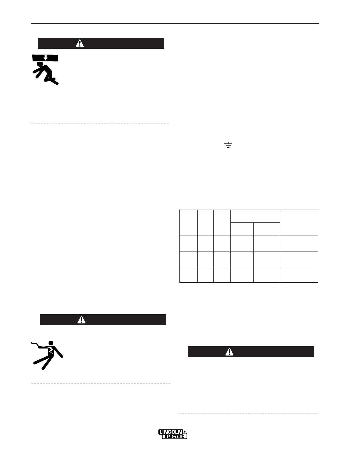
Recommended Input Wire,
Ground Wire and Fuse Sizes
Based on U.S. National Electrical Code.
For 60 hertz, 3 phase Welders at 60% Duty Cycle.
Copper Wire Size
Type 75°C in Conduit
Input Amps 3 Input 1 Ground Super Lag Fuse
Welder Volts Input Wires Wire Size inAmps
300 230 56.0 88 80
460 28.0 10 10 40
400 230 82.0 66 125
460 41.0 10 10 60
500 230 100.0 46 150
460 50.0 88 70
This welder is rated for 60% duty cycle. Duty cycle is
based on a ten minute period. Therefore, the welder
can be operated at nameplate rated output for 6 minutes of every 10 minute period without overheating.
An amber high temperature warning light provides a
visual indication of an over temperature condition.
CAUTION
Failure to follow these instructions can cause
immediate failure of components within the
machine.
When powering welder from a generator be sure to
turn off welder first, before generator is shut down,
in order to prevent damage to welder!
IDEALARC® R3R, -300, -400, -500

A-2
OUTPUT CONNECTIONS
INSTALLATION
TIG WELDING
A-2
OUTPUT STUDS
With the machine off, run electrode and work cables of
the appropriate sizes (see the following table) up
through the rectangular holes in the machine base
located below the output studs. Connect the cable lugs
to the output terminals marked (+) and (-) or, if the
welder comes equipped with the polarity switch option
“electrode” and “to work”. Tighten the holding nuts with
a wrench.
Cable Sizes for Combined Length of Electrode
and Work Cable (Copper) at 60% Duty Cycle
Machine Up to 100 ft. 100 to 150 ft. 150 to 200 ft. 200 to 250 ft.
Size (30 m) (30 – 46 m) (46 – 61 m) (61 – 76 m)
300 1/0 (54 mm
400 2/0 (68 mm2) 2/0 (68 mm2) 3/0 (86 mm2) 4/0 (108 mm2)
500 2/0 (68 mm2) 3/0 (86 mm2) 3/0 (86 mm2) 4/0 (108 mm2)
2
) 1/0 (54 mm2) 2/0 (68 mm2) 3/0 (86 mm2)
CONNECTION OF OPTIONAL REMOTE CONTROL
– K857
Turn the machine off. The K857 consists of a control
box with 28 feet (8.5m) of four conductor cable and a 6
pin connectorfor easy connection to the power source.
This control will give the same control as the current
control on the machine depending on the position of
the current dial selector switch. (There is no current
dial selector switch on the R3R-300.)
The R3R is shipped with proper R.F. By-pass circuitry
installed to protect the control circuit when TIG welding
with a Hi-Freq™ unit. To provide protection, the
welder frame grounding stud must be connected to
ground.
CAUTION
Extreme care must be observed when installing or
extending the wiring of a remote control. The
remote control cord can be lengthened to any
length by splicing four wires to the standard 28 ft.
(8.5m) cord before connecting to the R3R terminal
strip. Only the green lead can and should be
grounded to the machine case.
When extending the standard remote control make
sure the leads are the same and the splice is waterproof. Don’t let the lugs touch against the case.
OPTIONAL K963 HAND AMPTROLAND K870
FOOT AMPTROL
These amptrols connect directly to the 6-pin connector
on the front of the power source.
IDEALARC® R3R, -300, -400, -500

B-1
OPERATION
B-1
WARNING
ELECTRIC SHOCK can kill.
• Do not touch electrically live parts
or electrode with skin or wet clothing.
• Insulate yourself from work and ground.
• Always wear dry insulating gloves.
FUMES AND GASES can be dangerous.
• Keep your head out of fumes.
• Use ventilation or exhaust to
• remove fumes from breathing zone.
WELDING SPARKS can cause fire or
explosion.
• Keep flammable material away.
• Do not weld on containers that
have held combustibles.
ARC RAYS can burn.
• Wear eye, ear and body protection.
b. Provisions for remote control are standard on
each power source. A current control switch on
the machine control panel labeled “Current
Control at R3R” or “Current Control Remote” is
provided for selecting the desired mode of operation, eitherat themachine orremote, Becertain
the machine remote switch is in the machine
position, unless a remote control is connected,
or the R3R is equipped with optional pocket
amptrol.
c. The “ArcForce Control”,located onthe right side
of the front control panel, is calibrated from one
to ten. Lower settings will provide less short circuit current and a softer arc. Asetting that is too
low may cause the electrode to stick in the puddle. Higher settings will provide a higher short
circuit current, a more forceful arc, and possibly
more spatter. For most welding, the dial should
be set at approximately mid range (5 – 6).
Adjustment up or down can then be made
depending on the electrode, procedures, and
operator preference.For mostTIG weldingapplications adjust this control to minimum for best
operating characteristics.
3. Pocket Amptrol (Optional)
NOTE: The P.C. Board is protected by a moisture
resistant coating. When the welder is operated, this
coating will “bake off” of certain power resistors that
normally operate at high temperatures, emitting some
smoke and odor for a short time. These resistors and
the P.C. Board beneath them may become blackened.
This is a normal occurrence and does not damage the
component or affect the machine performance.
1. To Start the Welder, move the “Power” switch to
“On”. This starts thewelder and lights the whitepilot
light on the machine control panel. This light indicates that the line contactor is energized).
2. Setting Welding Current
a. The “Current Control” dial on the front of the
machine indicates the output current at the
NEMA arc voltage.
On R3R-300, one dial covers the complete
range. On the R3R-400 and -500, two dials are
used, The “A” range controls the current over
about 1/2 of the range of the “B” range. Atoggle
switch on the control panel allows selection of
the desired range. The output control can be
adjusted while welding.
IDEALARC® R3R, -300, -400, -500
The pocket amptrol option provides a remote current control for the R3R welders. This “wireless”
control requires no control cable connection to the
welder.
a. On the R3R-400 and -500 the welder “Current
Control” switch must be in the “Remote” position
and the “Current Dial Selector” switch in the “B”
range. The R3R-300 has only one dial and no
selection switch. The R3R-300 does not have a
“Current Dial Selector” switch. With the “Current
Control” switch in the “Remote” position, the current control potentiometer on the welder is
removed from the circuit and its setting has no
effect on the output. With the “Current Dial
Selector” switch in the “B” range position, the
pocket amptrol provides total control from NEMA
minimum to NEMA maximum output of the
welder.
b. Turn the welder power switch on.
c. Insert one end of the probe into the electrode
holder and hold the other end on the work for
approximately five seconds.
d. To change current, change the probe dial setting
and repeat the five second procedure of placing
the probe between electrode and work.
 Loading...