


Return to Master TOC |
View Safety Info |
Return to Master TOC |
View Safety Info |
Return to Master TOC |
View Safety Info |
Return to Master TOC |
View Safety Info |
RETURN TO MAIN INDEX
SVM136-A
November 1997
IDEALARC ® CV-400
For Machines with Code Numbers 10084 thru 10087
Safety Depends on You
Lincoln arc welding and cutting equipment is designed and built with safety in mind. However, your overall safety can be increased by proper installation . . .
and thoughtful operation on your part. DO NOT INSTALL,
OPERATE OR REPAIR THIS EQUIPMENT WITHOUT READING THIS MANUAL AND THE SAFETY PRECAUTIONS CONTAINED THROUGHOUT.
And, most importantly, think before you act and be careful.
SERVICE MANUAL
|
|
|
|
World’s Leader in Welding and Cutting Products |
|
|
Premier Manufacturer of Industrial Motors |
|
|
||
|
|
||
|
|
|
|
Sales and Service through subsidiaries and Distributors Worldwide
22801 St. Clair Ave. Cleveland, Ohio 44117-1199 U.S.A. Tel. (216) 481-8100
Return to Master TOC
Return to Master TOC
Return to Master TOC
Return to Master TOC
i |
i |
|
|
|
SAFETY |
 WARNING
CALIFORNIA PROPOSITION 65 WARNINGS
Diesel engine exhaust and some of its constituents |
|
The engine exhaust from this product contains |
are known to the State of California to cause can- |
|
chemicals known to the State of California to cause |
cer, birth defects, and other reproductive harm. |
|
cancer, birth defects, or other reproductive harm. |
|
|
|
The Above For Diesel Engines |
|
The Above For Gasoline Engines |
ARC WELDING CAN BE HAZARDOUS. PROTECT YOURSELF AND OTHERS FROM POSSIBLE SERIOUS INJURY OR DEATH. KEEP CHILDREN AWAY. PACEMAKER WEARERS SHOULD CONSULT WITH THEIR DOCTOR BEFORE OPERATING.
Read and understand the following safety highlights. For additional safety information, it is strongly recommended that you purchase a copy of “Safety in Welding & Cutting - ANSI Standard Z49.1” from the American Welding Society, P.O. Box 351040, Miami, Florida 33135 or CSA Standard W117.2-1974. A Free copy of “Arc Welding Safety” booklet E205 is available from the Lincoln Electric Company, 22801 St. Clair Avenue, Cleveland, Ohio 44117-1199.
BE SURE THAT ALL INSTALLATION, OPERATION, MAINTENANCE AND REPAIR PROCEDURES ARE PERFORMED ONLY BY QUALIFIED INDIVIDUALS.
FOR ENGINE powered equipment.
1.a. Turn the engine off before troubleshooting and maintenance work unless the maintenance work requires it to be running.
____________________________________________________
1.b. Operate engines in open, well-ventilated areas or vent the engine exhaust fumes outdoors.
____________________________________________________
1.c. Do not add the fuel near an open flame welding arc or when the engine is running. Stop
the engine and allow it to cool before refueling to prevent spilled fuel from vaporizing on contact with hot engine parts and igniting. Do not spill fuel when filling tank. If fuel is spilled, wipe it up and do not start engine until fumes have been eliminated.
____________________________________________________
1.d. Keep all equipment safety guards, covers and devices in position and in good repair.Keep hands, hair, clothing and tools away from V- belts, gears, fans and all other moving parts when starting, operating or repairing equip-
ment.
____________________________________________________
1.e. In some cases it may be necessary to remove safety guards to perform required maintenance. Remove guards only when necessary and replace them when the maintenance requiring their removal is complete. Always use the greatest care when working near moving parts.
___________________________________________________
1.f. Do not put your hands near the engine fan. Do not attempt to override the governor or idler by pushing on the throttle control rods while the engine is running.
___________________________________________________
1.g. To prevent accidentally starting gasoline engines while turning the engine or welding generator during maintenance work, disconnect the spark plug wires, distributor cap or magneto wire as appropriate.
1.h. To avoid scalding, do not remove the radiator pressure cap when the engine is hot.
ELECTRIC AND MAGNETIC FIELDS may be dangerous
2.a. Electric current flowing through any conductor causes localized Electric and Magnetic Fields (EMF). Welding current creates EMF fields around welding cables and welding machines
2.b. EMF fields may interfere with some pacemakers, and welders having a pacemaker should consult their physician before welding.
2.c. Exposure to EMF fields in welding may have other health effects which are now not known.
2.d. All welders should use the following procedures in order to minimize exposure to EMF fields from the welding circuit:
2.d.1. Route the electrode and work cables together - Secure them with tape when possible.
2.d.2. Never coil the electrode lead around your body.
2.d.3. Do not place your body between the electrode and work cables. If the electrode cable is on your right side, the work cable should also be on your right side.
2.d.4. Connect the work cable to the workpiece as close as possible to the area being welded.
2.d.5. Do not work next to welding power source.
Mar ‘95
IDEALARC CV-400

Return to Master TOC
Return to Master TOC
Return to Master TOC
Return to Master TOC
ii |
ii |
SAFETY
ELECTRIC SHOCK can kill.
3.a. The electrode and work (or ground) circuits are electrically “hot” when the welder is on. Do not touch these “hot” parts with your bare skin or wet clothing. Wear dry, hole-free gloves to insulate hands.
3.b. Insulate yourself from work and ground using dry insulation. Make certain the insulation is large enough to cover your full area of physical contact with work and ground.
In addition to the normal safety precautions, if welding must be performed under electrically hazardous conditions (in damp locations or while wearing wet clothing; on metal structures such as floors, gratings or scaffolds; when in cramped positions such as sitting, kneeling or lying, if there is a high risk of unavoidable or accidental contact with the workpiece or ground) use the following equipment:
•Semiautomatic DC Constant Voltage (Wire) Welder.
•DC Manual (Stick) Welder.
•AC Welder with Reduced Voltage Control.
3.c. In semiautomatic or automatic wire welding, the electrode, electrode reel, welding head, nozzle or semiautomatic welding gun are also electrically “hot”.
3.d. Always be sure the work cable makes a good electrical connection with the metal being welded. The connection should be as close as possible to the area being welded.
3.e. Ground the work or metal to be welded to a good electrical (earth) ground.
3.f. Maintain the electrode holder, work clamp, welding cable and welding machine in good, safe operating condition. Replace damaged insulation.
3.g. Never dip the electrode in water for cooling.
3.h. Never simultaneously touch electrically “hot” parts of electrode holders connected to two welders because voltage between the two can be the total of the open circuit voltage of both welders.
3.i. When working above floor level, use a safety belt to protect yourself from a fall should you get a shock.
3.j. Also see Items 6.c. and 8.
ARC RAYS can burn.
4.a. Use a shield with the proper filter and cover plates to protect your eyes from sparks and the rays of the arc when welding or observing open arc welding. Headshield and filter lens should conform to ANSI Z87. I standards.
4.b. Use suitable clothing made from durable flame-resistant material to protect your skin and that of your helpers from the arc rays.
4.c. Protect other nearby personnel with suitable, non-flammable screening and/or warn them not to watch the arc nor expose themselves to the arc rays or to hot spatter or metal.
FUMES AND GASES can be dangerous.
5.a. Welding may produce fumes and gases hazardous to health. Avoid breathing these fumes and gases.When welding, keep your head out of the fume. Use enough ventilation and/or exhaust at the arc to keep
fumes and gases away from the breathing zone. When welding with electrodes which require special ventilation such as stainless or hard facing (see instructions on container or MSDS) or on lead or cadmium plated steel and other metals or coatings which produce highly toxic fumes, keep exposure as low as possible and below Threshold Limit Values (TLV) using local exhaust or mechanical ventilation. In confined spaces or in some circumstances, outdoors, a respirator may be required. Additional precautions are also required when welding on galvanized steel.
5.b. Do not weld in locations near chlorinated hydrocarbon vapors coming from degreasing, cleaning or spraying operations. The heat and rays of the arc can react with solvent vapors to form phosgene, a highly toxic gas, and other irritating products.
5.c. Shielding gases used for arc welding can displace air and cause injury or death. Always use enough ventilation, especially in confined areas, to insure breathing air is safe.
5.d. Read and understand the manufacturer’s instructions for this equipment and the consumables to be used, including the material safety data sheet (MSDS) and follow your employer’s safety practices. MSDS forms are available from your welding distributor or from the manufacturer.
5.e. Also see item 1.b.
Mar ‘95
IDEALARC CV-400
Return to Master TOC
Return to Master TOC
Return to Master TOC
Return to Master TOC
iii |
|
SAFETY |
|
iii |
|
|
|
|

 WELDING SPARKS can
 cause fire or explosion.
6.a. Remove fire hazards from the welding area. If this is not possible, cover them to prevent the welding sparks from starting a fire. Remember that welding sparks and hot
materials from welding can easily go through small cracks and openings to adjacent areas. Avoid welding near hydraulic lines. Have a fire extinguisher readily available.
6.b. Where compressed gases are to be used at the job site, special precautions should be used to prevent hazardous situations. Refer to “Safety in Welding and Cutting” (ANSI Standard Z49.1) and the operating information for the equipment being used.
6.c. When not welding, make certain no part of the electrode circuit is touching the work or ground. Accidental contact can cause overheating and create a fire hazard.
6.d. Do not heat, cut or weld tanks, drums or containers until the proper steps have been taken to insure that such procedures will not cause flammable or toxic vapors from substances inside. They can cause an explosion even though they have been “cleaned”. For information, purchase “Recommended Safe Practices for the Preparation for Welding and Cutting of
Containers and Piping That Have Held Hazardous Substances”, AWS F4.1 from the American Welding Society
(see address above).
6.e. Vent hollow castings or containers before heating, cutting or welding. They may explode.
6.f. Sparks and spatter are thrown from the welding arc. Wear oil free protective garments such as leather gloves, heavy shirt, cuffless trousers, high shoes and a cap over your hair. Wear ear plugs when welding out of position or in confined places.
Always wear safety glasses with side shields when in a welding area.
6.g. Connect the work cable to the work as close to the welding area as practical. Work cables connected to the building framework or other locations away from the welding area increase the possibility of the welding current passing through lifting chains, crane cables or other alternate circuits.
This can create fire hazards or overheat lifting chains or cables until they fail.
6.h. Also see item 1.c.
CYLINDER may explode


 if damaged.
7.a. Use only compressed gas cylinders
containing the correct shielding gas for the process used and properly operating regulators designed for the gas and
pressure used. All hoses, fittings, etc. should be suitable for the application and maintained in good condition.
7.b. Always keep cylinders in an upright position securely chained to an undercarriage or fixed support.
7.c. Cylinders should be located:
•Away from areas where they may be struck or subjected to physical damage.
•A safe distance from arc welding or cutting operations and any other source of heat, sparks, or flame.
7.d. Never allow the electrode, electrode holder or any other electrically “hot” parts to touch a cylinder.
7.e. Keep your head and face away from the cylinder valve outlet when opening the cylinder valve.
7.f. Valve protection caps should always be in place and hand tight except when the cylinder is in use or connected for use.
7.g. Read and follow the instructions on compressed gas cylinders, associated equipment, and CGA publication P-l, “Precautions for Safe Handling of Compressed Gases in Cylinders,” available from the Compressed Gas Association
1235 Jefferson Davis Highway, Arlington, VA 22202.
FOR ELECTRICALLY powered equipment.
8.a. Turn off input power using the disconnect switch at the fuse box before working on the equipment.
8.b. Install equipment in accordance with the U.S. National
Electrical Code, all local codes and the manufacturer’s recommendations.
8.c. Ground the equipment in accordance with the U.S. National Electrical Code and the manufacturer’s recommendations.
Mar ‘95
IDEALARC CV-400

Return to Master TOC
Return to Master TOC
Return to Master TOC
Return to Master TOC
iv |
iv |
SAFETY
PRÉCAUTIONS DE SÛRETÉ
Pour votre propre protection lire et observer toutes les instructions et les précautions de sûreté specifiques qui parraissent dans ce manuel aussi bien que les précautions de sûreté générales suivantes:
Sûreté Pour Soudage A L’Arc
1.Protegez-vous contre la secousse électrique:
a.Les circuits à l’électrode et à la piéce sont sous tension quand la machine à souder est en marche. Eviter toujours tout contact entre les parties sous tension et la peau nue ou les vétements mouillés. Porter des gants secs et sans trous pour isoler les mains.
b.Faire trés attention de bien s’isoler de la masse quand on soude dans des endroits humides, ou sur un plancher metallique ou des grilles metalliques, principalement dans les positions assis ou couché pour lesquelles une grande partie du corps peut être en contact avec la masse.
c.Maintenir le porte-électrode, la pince de masse, le câble de soudage et la machine à souder en bon et sûr état defonctionnement.
d.Ne jamais plonger le porte-électrode dans l’eau pour le refroidir.
e.Ne jamais toucher simultanément les parties sous tension des porte-électrodes connectés à deux machines à souder parce que la tension entre les deux pinces peut être le total de la tension à vide des deux machines.
f.Si on utilise la machine à souder comme une source de courant pour soudage semi-automatique, ces precautions pour le porte-électrode s’applicuent aussi au pistolet de soudage.
2.Dans le cas de travail au dessus du niveau du sol, se protéger contre les chutes dans le cas ou on recoit un choc. Ne jamais enrouler le câble-électrode autour de n’importe quelle partie du corps.
3.Un coup d’arc peut être plus sévère qu’un coup de soliel, donc:
a.Utiliser un bon masque avec un verre filtrant approprié
ainsi qu’un verre blanc afin de se protéger les yeux du rayonnement de l’arc et des projections quand on soude ou quand on regarde l’arc.
b.Porter des vêtements convenables afin de protéger la peau de soudeur et des aides contre le rayonnement de l‘arc.
c.Protéger l’autre personnel travaillant à proximité au
soudage à l’aide d’écrans appropriés et non-inflammables.
4.Des gouttes de laitier en fusion sont émises de l’arc de soudage. Se protéger avec des vêtements de protection libres de l’huile, tels que les gants en cuir, chemise épaisse, pantalons sans revers, et chaussures montantes.
5.Toujours porter des lunettes de sécurité dans la zone de soudage. Utiliser des lunettes avec écrans lateraux dans les zones où l’on pique le laitier.
6.Eloigner les matériaux inflammables ou les recouvrir afin de prévenir tout risque d’incendie dû aux étincelles.
7.Quand on ne soude pas, poser la pince à une endroit isolé de la masse. Un court-circuit accidental peut provoquer un échauffement et un risque d’incendie.
8.S’assurer que la masse est connectée le plus prés possible de la zone de travail qu’il est pratique de le faire. Si on place la masse sur la charpente de la construction ou d’autres endroits
éloignés de la zone de travail, on augmente le risque de voir passer le courant de soudage par les chaines de levage, câbles de grue, ou autres circuits. Cela peut provoquer des risques d’incendie ou d’echauffement des chaines et des câbles jusqu’à ce qu’ils se rompent.
9.Assurer une ventilation suffisante dans la zone de soudage.
Ceci est particuliérement important pour le soudage de tôles galvanisées plombées, ou cadmiées ou tout autre métal qui produit des fumeés toxiques.
10.Ne pas souder en présence de vapeurs de chlore provenant d’opérations de dégraissage, nettoyage ou pistolage. La chaleur ou les rayons de l’arc peuvent réagir avec les vapeurs du solvant pour produire du phosgéne (gas fortement toxique) ou autres produits irritants.
11.Pour obtenir de plus amples renseignements sur la sûreté, voir le code “Code for safety in welding and cutting” CSA Standard W 117.2-1974.
PRÉCAUTIONS DE SÛRETÉ POUR LES MACHINES À SOUDER À TRANSFORMATEUR ET À REDRESSEUR
1.Relier à la terre le chassis du poste conformement au code de l’électricité et aux recommendations du fabricant. Le dispositif de montage ou la piece à souder doit être branché à une bonne mise à la terre.
2.Autant que possible, I’installation et l’entretien du poste seront effectués par un électricien qualifié.
3.Avant de faires des travaux à l’interieur de poste, la debrancher à l’interrupteur à la boite de fusibles.
4.Garder tous les couvercles et dispositifs de sûreté à leur place.
Mar. ‘93
IDEALARC CV-400

v |
|
v |
|||||||
|
|
MASTER TABLE OF CONTENTS FOR ALL SECTIONS |
|||||||
|
|
|
|
|
|
|
|||
|
|
|
RETURN TO MAIN INDEX |
|
Page |
||||
|
|
|
|
|
|
|
|
||
|
|
Safety ............................................................................................................................................... |
i-i-v |
||||||
|
|
|
|
|
|
|
|||
|
|
Installation............................................................................................................................. |
Section A |
||||||
|
|
Technical Specifications .............................................................................................................. |
A-2 |
||||||
|
|
Safety Precautions ...................................................................................................................... |
A-3 |
||||||
|
|
Location and Ventilation .............................................................................................................. |
A-3 |
||||||
|
|
Electrical Input Connections........................................................................................................ |
A-3 |
||||||
|
|
Reconnect Procedure ................................................................................................................. |
A-6 |
||||||
|
|
Output Connections .................................................................................................................... |
A-6 |
||||||
|
|
|
|
|
|
|
|||
|
|
Operation............................................................................................................................... |
Section B |
||||||
|
|
Safety Precautions ...................................................................................................................... |
B-2 |
||||||
|
|
General Description .................................................................................................................... |
B-3 |
||||||
|
|
Controls and Settings.................................................................................................................. |
B-5 |
||||||
|
|
Welding Operation ...................................................................................................................... |
B-6 |
||||||
|
|
Overload Protection .................................................................................................................... |
B-7 |
||||||
|
|
Auxiliary Power ........................................................................................................................... |
B-7 |
||||||
|
|
|
|
|
|
|
|||
|
|
Accessories .......................................................................................................................... |
Section C |
||||||
|
|
Options/Accessories ................................................................................................................... |
C-2 |
||||||
|
|
Connection of Lincoln Electric Automatic or Semiautomatic Wire Feeders |
...............................C-3 |
||||||
|
|
|
|
|
|
|
|||
|
|
Maintenance .......................................................................................................................... |
Section D |
||||||
|
|
Safety Precautions...................................................................................................................... |
D-2 |
||||||
|
|
Routine and Periodic Maintenance............................................................................................. |
D-2 |
||||||
|
|
Major Component Locations....................................................................................................... |
D-3 |
||||||
|
|
|
|
|
|
|
|||
|
|
Theory of Operation ............................................................................................................. |
Section E |
|
|||||
|
|
Troubleshooting and Repair ................................................................................................ |
Section F |
||||||
|
|
How to Use Troubleshooting Guide ............................................................................................ |
F-2 |
||||||
|
|
PC Board Troubleshooting Procedures ...................................................................................... |
F-3 |
||||||
|
|
Troubleshooting Guide ................................................................................................................ |
F-4 |
||||||
|
|
Test Procedures ........................................................................................................................ |
F-10 |
||||||
|
|
Oscilloscope Waveforms........................................................................................................... |
F-28 |
||||||
|
|
Replacement Procedures.......................................................................................................... |
F-32 |
||||||
|
|
Retest After Repair.................................................................................................................... |
F-53 |
||||||
|
|
|
|
|
|
|
|||
|
|
Parts Manual ............................................................................................................................... |
P - 236 |
||||||
|
|
|
IDEALARC CV-400 |
|
|
||||
|
|
|
|
|
|
|
|
DEC-97 |
|
|
|
|
|
|
|
|
|
||
|
|
|
|
|
|
|
|
||
|
|
|
|
|
|
|
|
|
|

Return to Master TOC
Return to Master TOC
Return to Master TOC
Return to Master TOC
Section A-1 |
Section A-1 |
|
|
TABLE OF CONTENTS |
|
|
- INSTALLATION SECTION - |
|
|
Installation............................................................................................................................. |
Section A |
|
Technical Specifications .............................................................................................................. |
A-2 |
|
Safety Precautions ...................................................................................................................... |
A-3 |
|
Location and Ventilation .............................................................................................................. |
A-3 |
|
Lifting .................................................................................................................................... |
A-3 |
|
Stacking ................................................................................................................................ |
A-3 |
|
Tilting .................................................................................................................................... |
A-3 |
|
Electrical Input Connections ....................................................................................................... |
A-3 |
|
Ground Connection............................................................................................................... |
A-4 |
|
Input Power Supply Connections.......................................................................................... |
A-4 |
|
Input Wire and Fuse Size ..................................................................................................... |
A-5 |
|
Reconnect Procedure ................................................................................................................. |
A-6 |
|
Output Connections .................................................................................................................... |
A-6 |
|
Connect Electrode and Work Leads to Output Terminals .................................................... |
A-6 |
|
Connect Wire Feeders.......................................................................................................... |
A-8 |
IDEALARC CV-400

Return to Section TOC |
Return to Master TOC |
Return to Section TOC |
Return to Master TOC |
Return to Section TOC |
Return to Master TOC |
Return to Section TOC |
Return to Master TOC |
A-2 |
|
|
|
|
INSTALLATION |
|
|
A-2 |
|
||||||||
|
|
|
|
|
|
|
|
|
|
|
|
||||||
|
TECHNICAL SPECIFICATIONS - IDEALARC CV-400 |
|
|
|
|
||||||||||||
|
|
|
|
|
|
|
|
|
|
|
|
|
|
|
|
|
|
|
|
|
|
|
|
INPUT - THREE |
PHASE ONLY |
|
|
|
|
||||||
|
Standard Voltage |
|
|
|
|
|
Input Current at Rated Output |
|
|||||||||
|
|
|
|
230/460 |
|
|
|
|
|
77A/39A @ 400A 36V |
|
||||||
|
|
|
|
|
|
|
|
|
|
|
|
|
|
|
|
|
|
|
|
|
|
|
|
|
|
RATED |
OUTPUT |
|
|
|
|
|
|||
|
Duty Cycle |
|
|
|
Welding Output |
|
Volts at Rated Amps |
|
|||||||||
|
100% |
|
|
|
|
|
400 |
|
|
|
|
|
|
36* |
|
||
|
60% |
|
|
|
|
|
450 |
|
|
|
|
|
|
38 |
|
||
|
50% |
|
|
|
|
|
500 |
|
|
|
|
|
|
40 |
|
||
|
|
|
|
|
|
|
|
|
|
|
|
|
|
|
|
|
|
|
|
|
|
|
|
|
|
|
OUTPUT |
|
|
|
|
|
|||
|
Current |
|
|
|
Voltage |
|
|
Maximum Open |
|
|
Auxiliary |
|
|||||
|
Range |
|
|
|
Range |
|
|
Circuit Voltage |
|
|
Power |
|
|||||
|
60 - 500 Amps |
|
|
12 - 42 Volts |
|
|
|
|
|
46 VDC |
|
|
115 VAC, 10 Amps |
|
|||
|
|
|
|
|
|
|
|
|
|
|
|
|
|
|
|
42 VAC, 10 Amps |
|
|
|
|
|
|
|
|
|
|
|
|
|
|
|
|
|||
|
|
|
RECOMMENDED |
|
|
INPUT WIRE AND FUSE SIZES |
|
||||||||||
|
|
|
|
|
|
|
|
|
Fuse |
Type 75° C |
Type 75° C |
|
|||||
|
Input Voltage/ |
|
Input Amps |
|
(Super Lag) |
Copper Wire in |
Copper Ground |
|
|||||||||
|
Frequency |
|
Rating on |
|
or Breaker |
Conduit AWG |
Wire in Conduit |
|
|||||||||
|
Volts/Hz |
|
Nameplate |
|
|
Size |
(IEC) Sizes |
AWG (IEC) Sizes |
|
||||||||
|
230 |
|
|
77 |
|
125 |
|
|
3 (27 mm2) |
|
|
6 (13 mm2) |
|
||||
|
460 |
|
|
39 |
|
60 |
|
|
8 (8.4 mm2) |
|
|
10 (5.3 mm2) |
|
||||
|
|
|
|
|
|
|
|
|
|
|
|
|
|
|
|
|
|
|
|
|
|
|
|
|
PHYSICAL DIMENSIONS |
|
|
|
|
||||||
|
Height2 |
|
|
Width |
|
Depth |
|
|
Weight |
|
|||||||
|
27.5 in. (699 mm) |
|
|
22.2 in. (565 mm) |
|
32.0 in. (813 mm) |
|
|
357 lbs. (162 kg) |
|
|||||||
|
|
|
|
|
|
|
|
|
|
|
|
|
|
|
|
|
|
* No added capacity over NEMA rated 36V at 400 amps.
IDEALARC CV-400
Return to Section TOC |
Return to Master TOC |
Return to Section TOC |
Return to Master TOC |
Return to Section TOC |
Return to Master TOC |
Return to Section TOC |
Return to Master TOC |
A-3 |
A-3 |
INSTALLATION
Read this entire installation section before you start installation.
SAFETY PRECAUTIONS
WARNING
ELECTRIC SHOCK can kill.
•Do not touch electrically live parts such as output terminals or internal wiring.
•Insulate yourself from the work and ground.
•Turn power switch off before connecting or disconnecting cables or connections.
•Always connect grounding terminal to a proper electrical earth ground.
Only qualified personnel should install, use, or service this equipment.
The IDEALARC CV-400 weighs 357 pounds (162 kilograms). A permanent lift hook is located at the top of the machine, positioned at the center of gravity for stable lifting.
STACKING
IDEALARC CV-400s may be stacked three high. The bottom machine must be on a stable, hard, level surface capable of supporting the weight of up to three machines (1071 pounds/486 kilograms). Be sure that the two holes in the top front corners of the bottom machine line up with the holes in the base rails of the machine above. Fasten the machines together with 5/16" bolts, lockwashers, and nuts through these holes. The lift hook is positioned so that it fits without interference under the base of the second machine.
TILTING
Place the machine on a secure, level surface. Any surfaces you place it on other than the ground must be firm, non-skid, and structurally sound.
LOCATION AND VENTILATION
Place the IDEALARC CV-400 where clean, cooling air can flow freely in through the front louvers and out through the rear louvers. Keep dust, dirt, and other foreign materials that can be drawn into the machine to a minimum. Failure to observe these precautions can lead to excessive operating temperatures and nuisance shut-downs.
THE CV-400 carries an IP-21 environmental rating. Locate indoors or shelter from falling water such as rain.
ELECTRICAL INPUT CONNECTIONS
Be sure the voltage, phase, and frequency of the input power is as specified on the rating plate, located on the case front control panel. See Figure A.1.
Input supply line entry is through a hole in the case rear top panel. A removable door covers the input connection box, which contains the input contactor (CR1) and reconnect panel assembly for multiple voltage connection. Input power is connected to the three line terminals on the input contactor. See Figure A.2.
LIFTING
WARNING
FALLING EQUIPMENT can cause injury.
• Do not lift this machine using the lift hook if it is equipped with a heavy accessory such as a trailer or a gas cylinder.
•Lift only with equipment of adequate lifting capacity.
•Be sure the machine is stable when lifting.
•Do not stack more than three high.
•Do not stack the CV-400 on top of any other machine.
IDEALARC CV-400

Return to Section TOC |
Return to Master TOC |
Return to Section TOC |
Return to Master TOC |
Return to Section TOC |
Return to Master TOC |
Return to Section TOC |
Return to Master TOC |
A-4 |
A-4 |
INSTALLATION
FIGURE A.1
RATING PLATE LOCATION
1
1. RATING PLATE
GROUND CONNECTION
The frame of the welder must be grounded. An earth grounding lead must be connected to the grounding terminal, marked on the input box floor with the symbol  (See Figure A.2). Refer to Technical Specifications page for proper ground wire size.
INPUT SUPPLY CONNECTIONS
Be sure the voltage, phase, and frequency of the input power is the same as specified on the rating plate.
WARNING
ELECTRIC SHOCK can kill.
• Have a qualified electrician install and service this equipment.
•Turn the input power off at the fuse box before working on this equipment.
•Do not touch electrically hot parts.
IDEALARC CV-400
Return to Section TOC |
Return to Master TOC |
Return to Section TOC |
Return to Master TOC |
Return to Section TOC |
Return to Master TOC |
Return to Section TOC |
Return to Master TOC |
A-5 |
A-5 |
INSTALLATION
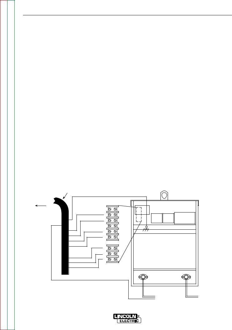
FIGURE A.2 REAR PANEL
INPUT WIRE AND FUSE SIZE
Fuse the input circuit with the super lag fuse recommended in the Technical Specifications at the beginning of this section or use delay type1 circuit breakers. Choose an input and grounding wire size according to local or national codes; also see the Technical Specifications. Using fuses or circuit breakers smaller than recommended may result in "nuisance" shut-offs from welder inrush currents, even if you are not welding at high output currents.
1Also called "inverse time" or "thermal/magnetic" circuit breakers. These circuit breakers trip faster as the magnetude of the fault current increases.
FIGURE A.3
INPUT POWER SUPPLY CONNECTIONS
1.INPUT SUPPLY LINE ENTRY HOLE
2.INPUT CONTACTOR CR1
3.RECONNECT PANEL/JUMPER LINKS
4.GROUND TERMINAL
Have a qualified electrician connect the input power leads to the L1, L2, and L3 terminals of the input contactor. Follow all national and local electrical codes. Use a three-phase line. Install the reconnect panel jumper links (see Figure A.3) for the proper input voltage. See the connection diagram located on the inside cover of the access panel cover. Also refer to Reconnect Procedure later in this section.
1.INPUT SUPPLY LINE
2.INPUT CONTACTOR
3.RECONNECT PANEL/JUMPER LINKS
IDEALARC CV-400

Return to Section TOC |
Return to Master TOC |
Return to Section TOC |
Return to Master TOC |
Return to Section TOC |
Return to Master TOC |
Return to Section TOC |
Return to Master TOC |
A-6 |
A-6 |
|
|
|
INSTALLATION |
|
RECONNECT PROCEDURE |
OUTPUT CONNECTIONS |
Multiple input voltage welders are shipped from the factory connected for the highest voltage listed on the machine's rating plate. Before installing the welder, be sure the reconnect panel is connected for the proper voltage.
Failure to follow these instructions can cause immediate failure of components in the welder.
To reconnect a multiple voltage machine to a different voltage, remove input power and change the position of the jumper links on the reconnect panel. Follow the input connection diagram, located on the inside access panel cover, appropriate for your machine's input voltage. This same connection diagram is shown in Figure A.4 below.
CONNECT ELECTRODE AND WORK LEADS TO OUTPUT TERMINALS
The output (welding) cables are connected to the output terminals marked "+" and "-" . These 1/2" terminals are located at the lower right and lower left corners of the front panel. See Figure A.5.
See Table A.1 for recommended cable sizes for combined lengths of electrode and work cables.
FIGURE A.4
INPUT CONNECTION DIAGRAM FOR 230/460 VOLTS AC, 50/60 HZ
|
|
|
|
|
DUAL VOLTAGE MACHINE |
|
|
Do not operate with covers |
Do not touch electrically live parts |
INPUT SUPPLY CONNECTION DIAGRAM |
|
|
|
removed |
|
|
IMPORTANT: CHANGE LINK POSITIONS AND PILOT TRANSFORMER CONNECTIONS. |
|
|
Disconnect input power before Only qualified persons should install, |
|||
|
|
NOTE: MACHINES ARE SHIPPED FROM FACTORY CONNECTED FOR OVER 300 VOLTS |
|||
|
|
servicing |
|
use or service this equipment |
|
|
|
|
CONNECTION FOR HIGHEST RATING PLATE VOLTAGE, 50 OR 60 HZ. |
||
LINK |
|
|
|
|
1. TURN OFF THE INPUT POWER USING THE DISCONNECT SWITCH AT THE FUSE BOX. |
|
|
L3 |
W CR1 |
|
2. DISCONNECT AND INSULATE THE H2 LEAD TERMINAL WITH TAPE TO PROVIDE AT |
LINES |
|
|
|
LEAST 600 VOLT INSULATION. |
|
L2 |
V |
|
3. CONNECT L1, L2 & L3 INPUT SUPPLY LINES AND H3 TRANSFORMER LEADS |
||
INPUT |
|
||||
CONTACTOR |
|
||||
|
{L1 |
U |
|
TO THE INPUT SIDE OF THE CR1 CONTACTOR AS SHOWN. |
|
|
|
4. CONNECT TERMINAL MARKED TO GROUND PER LOCAL AND NATIONAL ELECTRIC |
|||
|
|
GND |
H1 |
H2 |
CODES. |
|
|
|
H3 |
5. MOUNT THE LINKS IN THE POSITIONS SHOWN WITH THE PROVIDED HEX NUTS. |
|
|
|
|
PILOT |
|
DOUBLE UP THE LINKS IN TWO OF THE POSITIONS TO SAVE THEM FOR FUTURE |
|
|
|
TRANSF. |
|
USE. SECURE THE REMAINING HEX NUTS IN PLACE. |
|
|
|
CONNECTION FOR LOWEST RATING PLATE VOLTAGE, 50 OR 60 HZ. |
||
LINK |
|
|
|
|
1. TURN OFF THE INPUT POWER USING THE DISCONNECT SWITCH AT THE FUSE BOX. |
LINES |
L3 |
W CR1 |
|
2. DISCONNECT AND INSULATE THE H3 LEAD TERMINAL WITH TAPE TO PROVIDE AT |
|
L2 |
V |
|
LEAST 600 VOLT INSULATION. |
||
INPUT |
|
3. CONNECT L1, L2 & L3 INPUT SUPPLY LINES AND H2 TRANSFORMER LEADS |
|||
CONTACTOR |
|
||||
|
{L1 |
U |
|
TO THE INPUT SIDE OF THE CR1 CONTACTOR AS SHOWN. |
|
|
|
GND |
H1 |
|
4. CONNECT TERMINAL MARKED TO GROUND PER LOCAL AND NATIONAL ELECTRIC |
|
|
H2 |
H3 |
CODES. |
|
|
|
|
|
||
|
|
|
PILOT |
|
5. MOUNT THE LINKS IN THE POSITIONS SHOWN WITH THE PROVIDED HEX NUTS. |
|
|
|
TRANSF. |
|
|
THE LINCOLN ELECTRIC CO., CLEVELAND OHIO U.S.A.
IDEALARC CV-400

A-7
Return to Section TOC |
Return to Master TOC |
Return to Section TOC |
Return to Master TOC |
Return to Section TOC |
Return to Master TOC |
Return to Section TOC |
Return to Master TOC |
A-7
INSTALLATION
FIGURE A.5
OUTPUT TERMINAL CONNECTIONS
1 |
2 |
 - +
- +
1.NEGATIVE (-) WELDING CABLE CONNECTION
2.POSITIVE (+) WELDING CABLE CONNECTION
TABLE A.1 - CABLE SIZES FOR COMBINED LENGTH
OF ELECTRODE AND WORK CABLE
|
MACHINE LOAD |
|
|
400A |
500A |
|
(100% DUTY |
(50% DUTY |
CABLE LENGTHS |
CYCLE) |
CYCLE) |
|
|
|
UP TO 50 ft |
3/0 |
2/0 |
(15 m) |
85 mm2 |
67 mm2 |
|
|
|
50 to 100 ft |
3/0 |
2/0 |
(15 to 30 m) |
85 mm2 |
67 mm2 |
|
|
|
100 to 150 ft |
3/0 |
3/0 |
(30 to 46 m) |
85 mm2 |
85 mm2 |
|
|
|
150 to 200 ft |
3/0 |
3/0 |
(46 to 61 m) |
85 mm2 |
85 mm2 |
|
|
|
200 to 250 ft |
4/0 |
4/0 |
(67 to 76 m) |
107 mm2 |
107 mm2 |
|
|
|
IDEALARC CV-400

Return to Section TOC |
Return to Master TOC |
Return to Section TOC |
Return to Master TOC |
Return to Section TOC |
Return to Master TOC |
Return to Section TOC |
Return to Master TOC |
A-8 |
A-8 |
INSTALLATION
CONNECT WIRE FEEDERS
The wire feeder control cable can connect to the CV400 at the 14-pin amphenol on the front of the machine (with the appropriate adapter cable) or the terminal strips behind the hinged control panel cover. A strain relief box connector is provided for cable access to the terminal strips. The wire feeder grounding wire connects to a chassis ground screw provided near the terminal strips and marked with the ground symbol  . See the Accessories section of this manual for specific instructions for connecting the following automatic and semiautomatic wire feeders to the CV-400:
Automatic Wire Feeders: NA-3, NA-5, NA-5R.
Semiautomatic Wire Feeders: LN-7, LN-7 GMA, LN-8,
LN-9, LN-9 GMA, LN-22, LN-23P, LN-25, LN-742.
IDEALARC CV-400

Return to Master TOC
Return to Master TOC
Return to Master TOC
Return to Master TOC
Section B-1 Section B-1
TABLE OF CONTENTS - OPERATION SECTION -
Operation............................................................................................................................... |
Section B |
Safety Precautions ...................................................................................................................... |
B-2 |
General Description .................................................................................................................... |
B-3 |
Recommended Processes.................................................................................................... |
B-3 |
Operational Features and Controls ...................................................................................... |
B-3 |
Design Features .................................................................................................................. |
B-3 |
Welding Capability ................................................................................................................ |
B-4 |
Limitations............................................................................................................................. |
B-4 |
Controls and Settings.................................................................................................................. |
B-5 |
Welding Operation....................................................................................................................... |
B-6 |
Local Control......................................................................................................................... |
B-6 |
Remote Control..................................................................................................................... |
B-6 |
Overload Protection .................................................................................................................... |
B-7 |
Auxiliary Power............................................................................................................................ |
B-7 |
IDEALARC CV-400

B-2
Return to Section TOC |
Return to Master TOC |
Return to Section TOC |
Return to Master TOC |
Return to Section TOC |
Return to Master TOC |
Return to Section TOC |
Return to Master TOC |
B-2
OPERATION
OPERATING INSTRUCTIONS
Read and understand this entire section of operating instructions before operating the machine.
SAFETY INSTRUCTIONS
WARNING
ELECTRIC SHOCK can kill.
•Do not touch electrically live parts or electrodes with your skin or wet clothing.
•Insulate yourself from the work and ground.
•Always wear dry insulating gloves.
FUMES AND GASES can be  dangerous.
• Keep your head out of fumes.
•Use ventilation or exhaust to remove fumes from breathing zone.


 WELDING SPARKS can cause
 fire or explosion.
•Keep flammable material away.
•Do not weld on containers that have held combustibles.
ARC RAYS can burn.
• Wear eye, ear, and body protection.
Observe additional Safety Guidelines detailed in the beginning of this manual.
IDEALARC CV-400

Return to Section TOC |
Return to Master TOC |
Return to Section TOC |
Return to Master TOC |
Return to Section TOC |
Return to Master TOC |
Return to Section TOC |
Return to Master TOC |
B-3 |
B-3 |
OPERATION
GENERAL DESCRIPTION
The IDEALARC CV-400 is an SCR controlled threephase input, DC output power source for welding. It uses a single range potentiometer control. The welder's unique combination of transformer, three phase hybrid rectifier, capacitor bank, output choke, and solid state control system deliver outstanding performance.
RECOMMENDED PROCESSES
The IDEALARC CV-400 is a constant voltage power source only. It is recommended for all open arc processes including Innershield and all solid wire and gas procedures within its capacity of 60 to 500 amps.
The CV-400 can be connected to wire feeding equipment, including:
•Automatic wire feeders NA-3, NA-5, and NA-5R. (Requires the CV-400 Diode Kit option to use the cold start and cold electrode sensing features of these feeders.)
•Semiautomatic wire feeders LN-7, LN-7 GMA, LN8, LN-9, LN-9 GMA, LN-22, LN23P, LN-25, and LN-742.
OPERATIONAL FEATURES AND CONTROLS
The following operational controls are standard on the IDEALARC CV-400:
•Power Source Pilot Light
•ON/OFF Power Toggle Switch
•Output Control Potentiometer
•Output Control Switch (with Local or Remote positions)
•Auxiliary Power Connections for Wire Feeder and Other Equipment (115V and 42V)
•Thermal Protection Indicator Light
•Voltmeter "+" Electrode or "-" Electrode Switch
DESIGN FEATURES
•Input line voltage compensation keeps output constant for fluctuations of ±10%.
•SCR control.
•Hinged front control panel provides easy access to printed circuit boards and other control circuitry.
•Fully enclosed fan motor with permanently lubricated, sealed ball bearings needs no maintenance.
•Fully recessed control panel protects controls and minimizes accidental contact.
•Recessed output terminals reduce chance of accidental contact.
•Low profile case permits installation under a workbench.
•Removable rear access panel provides easy access to input contactor and input lead connections.
•Removable case sides provide easy access for service or inspection, even when machines are stacked.
•Double-dipped transformer, SCR bridge, and choke resist corrosion.
IDEALARC CV-400

Return to Section TOC |
Return to Master TOC |
Return to Section TOC |
Return to Master TOC |
Return to Section TOC |
Return to Master TOC |
Return to Section TOC |
Return to Master TOC |
B-4 |
B-4 |
OPERATION
WELDING CAPABILITY
The CV-400 has the following duty cycle ratings. If the duty cycle is exceeded, a thermal protector will shut off the machine output until it cools to normal operating temperature. The amber thermal protection indicator light will turn on until the machine cools.
Duty Cycle* |
Amps |
Volts |
100% |
400 |
36 |
60% |
450 |
38 |
50% |
500 |
40 |
*Based on a 10 minute time period. For example, a 60% duty cycle means 6 minutes on and 4 minutes off.
LIMITATIONS
The IDEALARC CV-400 has no provisions for paralleling. It should not be used outdoors without rain sheltering.
IDEALARC CV-400

Return to Section TOC |
Return to Master TOC |
Return to Section TOC |
Return to Master TOC |
Return to Section TOC |
Return to Master TOC |
Return to Section TOC |
Return to Master TOC |
B-5 |
B-5 |
OPERATION
CONTROLS AND SETTINGS
All operator controls and settings are located on the case front assembly. See Figure B.1 for their locations.
FIGURE B.1 – CASE FRONT CONTROLS
|
|
8 |
9 |
10 |
11 |
|
|
|
|
|
1 |
|
|
|
|
|
2 |
7 |
6 |
5 |
|
4 |
3 |
1. POWER SOURCE PILOT LIGHT |
6. DC AMMETER |
2. ON/OFF POWER TOGGLE SWITCH |
7. AUXILIARY POWER CONNECTIONS FOR WIRE FEEDER AND |
3. OUTPUT CONTROL POTENTIOMETER |
OTHER EQUIPMENT (115V AND 42V) |
4. OUTPUT CONTROL SWITCH (WITH LOCAL OR |
8. VOLTMETER "+" ELECTRODE OR "-" ELECTRODE SWITCH |
REMOTE POSITIONS) |
9. THERMAL PROTECTION INDICATOR LIGHT |
5. DC VOLTMETER |
|
1.POWER SOURCE PILOT LIGHT: This light indicates that the power source input contactor is energized (closed). This also means that the main power transformer and all auxiliary control transformers are energized.
2.ON/OFF POWER TOGGLE SWITCH: Energizes or deengergizes the input contactor. The switch turns the machine ON or OFF. Position "I" is ON; position "0" is OFF.
3.OUTPUT CONTROL POTENTIOMETER: Controls output voltage.
4.OUTPUT CONTROL SWITCH (WITH LOCAL OR REMOTE POSITIONS): Selects the mode of control. In the "Local" position, control is by the machine control panel. In the "Remote" position, control is by either a wire feeder unit or through an optional remote control device.
5.DC VOLTMETER (OPTIONAL): Displays actual output voltage.
6.DC AMMETER (OPTIONAL): Displays actual output current.
7.AUXILIARY POWER AND REMOTE CONTROL CONNECTIONS FOR WIRE FEEDER AND OTHER EQUIPMENT (115V AND 42V): The 14-pin amphenol receptacle provides either 115 or 42 VAC as well as remote control connections. Terminal strips with screw connections are located behind the hinged control panel for hard wired control. A strain relief connector is provided for cable entry. The 42 VAC auxiliary is not available at the terminal strip.
8.VOLTMETER "+" ELECTRODE OR "-" ELECTRODE SWITCH: Selects the electrode polarity for the remote work sensing lead (#21) when using automatic or semiautomatic wire feeders. It must agree with the actual electrode polarity chosen and with the wire feeder polarity switch on the feeder.
9.THERMAL PROTECTON INDICATOR LIGHT: This light indicates that either of the two protective thermostats has opened. Welding output is disabled but input power is still applied.
10.42 VAC AUXILIARY CIRCUIT BREAKER: This 10 amp breaker protects the 42 VAC auxiliary circuit.
11.115 VAC AUXILIARY CIRCUIT BREAKER: This 10 amp breaker protects the 115 VAC auxiliary circuit.
IDEALARC CV-400

Return to Section TOC |
Return to Master TOC |
Return to Section TOC |
Return to Master TOC |
Return to Section TOC |
Return to Master TOC |
Return to Section TOC |
Return to Master TOC |
B-6 |
B-6 |
OPERATION
WELDING OPERATION
LOCAL CONTROL
The following procedures are for using the CV-400 in the local control mode of operation. For remote control of the machine, see the Remote Control section.
Before operating the machine, make sure you have all materials needed to complete the job. Be sure you are familiar with and have taken all possible safety precautions before starting work. It is important that you follow these operating steps each time you use the machine.
1.Turn on the main AC input power to the machine.
2.Set the VOLTMETER "+" or "-" switch to the appropriate position.
-Set toggle to " Electrode Negative" position if the electrode is connected to the negative (-) output terminal.
-Set toggle to "Electrode Positive" position if the electrode is connected to the positive (+) output terminal.
3.Set the OUTPUT CONTROL switch to "Local." (Exception: when using an LN-9, LN-9 GMA, or NA- 5 wire feeder, set the switch to "Remote." Otherwise, the wire feeder may automatically shut down.)
4.Set the ON/OFF switch to the ON position (I). The power source pilot light glows and the fan starts.
5.Set the OUTPUT CONTROL Potentiometer to the desired voltage.
6.Make the weld.
REMOTE CONTROL
The toggle switch on the control panel labeled "Output Control Remote" gives you the option of controlling the machine output from a remote location. In the "Remote" position a wire feeder with remote control capabilities or a remote control device such as a K775 must be connected to the CV-400. See the Accessories section for wire feeder installation information.
IDEALARC CV-400
Return to Section TOC |
Return to Master TOC |
Return to Section TOC |
Return to Master TOC |
Return to Section TOC |
Return to Master TOC |
Return to Section TOC |
Return to Master TOC |
B-7 |
B-7 |
OPERATION
OVERLOAD PROTECTION
The power source is thermostatically protected with proximity thermostats against overload or insufficient cooling. One thermostat is located on the nose of the center bottom primary coil and a second thermostat is attached to the lead connecting the secondaries. Both thermostats are connected in series with 2-4 circuit. If the machine is overloaded, the primary thermostat will open, the output will be zero, the amber thermal protection light will be on and the fan will continue to run. The secondary thermostat will open either with an excessive overload or insufficient cooling. The output will be zero, the amber protection light will be on and the fan will continue to run. When the thermostats reset, the protection light will be off.
The power source is also protected against overloads on the SCR bridge assembly through the solid state fault protection circuit. This circuit senses an overload on the power source and limits the output to approximately 550 amps by phasing back the SCR’s.
Protection is provided to protect the circuitry from accidental grounds. If leads 75, 76, or 77 are accidentally “grounded” to the positive output lead, the output will be reduced to a low value, thus preventing any damage to the machine. If the ground occurs between 75, 76, 77 and the negative output lead, one of the PC board electronic “self-restoring” fuses will blow, preventing any machine damage. After the ground is cleared, the fuses automatically reset within a few seconds.
AUXILIARY POWER
On machines above code 9400, the IDEALARC CV400 can provide nominally 115 volts AC and 42 volts AC auxiliary power for operating wire feeding equipment and other accessories. This power is available at the 14-pin amphenol on the control panel and/or at the terminal strip behind the hinged control panel on the case front. On the amphenol, 115 volts AC is available at pins A and J (Domestic and Export models only); 42 volts AC is available at pins I and K. On the terminal strip, 115 volts AC is available at terminals 31 and 32; 42 volts AC is not available at the terminal strip. The two circuits, 115 volts AC and 42 volts AC, are isolated; and each is protected by a 10 amp circuit breaker.
FRONT VIEW OF 14-PIN CONNECTOR
RECEPTACLE
|
K=42 |
A=32 |
J=31 |
B=GND |
I=41 |
L |
N |
C=2 |
H=21 |
D=4 |
G=75 |
E=77 |
F=76 |
|
M |
PIN |
LEAD NO. |
FUNCTION |
A |
32 |
115 VAC |
B |
GND |
Chassis Connection |
C |
2 |
Trigger Circuit |
D |
4 |
Trigger Circuit |
E |
77 |
Output Control |
F |
76 |
Output Control |
G |
75 |
Output Control |
H |
21 |
Work Connection |
I |
41 |
42 VAC |
J |
31 |
115 VAC |
K |
42 |
42 VAC |
L |
--- |
--- |
M |
--- |
--- |
N |
--- |
--- |
|
|
|
IDEALARC CV-400

B-8
Return to Section TOC |
Return to Master TOC |
Return to Section TOC |
Return to Master TOC |
Return to Section TOC |
Return to Master TOC |
Return to Section TOC |
Return to Master TOC |
B-8
NOTES
IDEALARC CV-400

Return to Master TOC
Return to Master TOC
Return to Master TOC
Return to Master TOC
Section C-1 Section C-1
TABLE OF CONTENTS |
|
- ACCESSORIES - |
|
Accessories........................................................................................................................... |
Section C |
Options/Accessories ................................................................................................................... |
C-2 |
Options/Accessories............................................................................................................. |
C-2 |
Factory Installed Options...................................................................................................... |
C-2 |
Field Installed Options.......................................................................................................... |
C-2 |
Connection of Lincoln Electric Automatic or Semiautomatic Wire Feeders................................ |
C-3 |
Automatic Wire Feeders NA-3, NA-5.................................................................................... |
C-3 |
Semiautomatic Wire Feeders LN-7, LN-8, LN-9................................................................... |
C-6 |
IDEALARC CV-400

Return to Section TOC |
Return to Master TOC |
Return to Section TOC |
Return to Master TOC |
Return to Section TOC |
Return to Master TOC |
Return to Section TOC |
Return to Master TOC |
C-2 |
C-2 |
ACCESSORIES
OPTIONS/ACCESSORIES
The following options/accessories are available for your CV-400 from your local Lincoln Electric Distributor.
FACTORY INSTALLED OPTIONS
Diode Option - This internally installed option allows use of the cold start and cold electrode sensing features of the NA-3, NA-5, or NA-5R automatic wire feeders. See the topic Connecting the NA-3 [NA-5] to the CV-400.
Ammeter and Voltmeter - Display output current and voltage when welding.
FIELD INSTALLED OPTIONS
The following options/accessories are available from your local Lincoln Distributor.
Undercarriage (K817P) - Includes a platform and polyolefin wheels for easily moving the welder.
Undercarriage (K841) - Includes a platform, wheels, and brackets for supporting the welder and two gas cylinders.
Remote Output Control (K775 or K857 with K864 Adapter Plug) - The K857 has a 6-pin MS-style connector. The K857 requires a K864 adapter cable which connects to the 14-pin connector on the CV-400.
The K775 consists of a control box with 28 ft (8.5m) of four conductor cable. This connects to terminals 75, 76, and 77 on the terminal strip and the case grounding screw marked with the symbol  on the machine. These terminals are located behind the control panel on the front. These devices will give the same control as the output control on the machine.
Remote Control Adapter Cable (K864) - A "V" cable 12 inches (.30 m) long to connect a K857 Remote Control with a wire-feeder control cable (14-pin connector) and the machine (14-pin connector). If a remote control is used alone, the wire-feeder connection is not used. See Figure C.1.
Capacitor Discharge Circuit (K828-1) - Mounts inside the CV-400. Recommended when:
•CV-400 is used in conjunction with any LN-23P or older LN-8 or LN-9 semiautomatic wire-feeder. Eliminates possible arc flash re-start of weld when trigger interlock is used. Not required with current LN- 8 (above Code 8700), or LN-9s with serial numbers above 115187 (manufactured after 12/83), or any LN- 9 having an L6043-1 Power PC Board.
•CV-400 is used with an LN-22 equipped with an older K279 Contactor-Voltage Control Option. Eliminates electrode overrun when gun trigger is released. Not required when later K279 (above Code 8800) is used.
•A small spark is objectionable if electrode touches work just after the trigger is released.
FIGURE C.1
REMOTE CONTROL ADAPTER CABLE (K864)
|
|
CABLE RECEPTACLE (6 SOCKET) |
|
STRAIGHT PLUG (14 PIN) |
|||
|
TO K857 REMOTE CONTROL |
||
TO POWER SOURCE |
|
||
|
|
||
|
|
|
|
|
|
|
CABLE RECEPTACLE (14 SOCKET)
TO: L-7 WIRE FEEDER
IDEALARC CV-400

Return to Section TOC |
Return to Master TOC |
Return to Section TOC |
Return to Master TOC |
Return to Section TOC |
Return to Master TOC |
Return to Section TOC |
Return to Master TOC |
C-3 |
C-3 |
ACCESSORIES
CONNECTION OF LINCOLN ELECTRIC AUTOMATIC OR SEMIAUTOMATIC WIRE FEEDERS
WARNING
ELECTRIC SHOCK can kill.
•Only qualified personnel should perform this maintenance.
•Turn the input power OFF at the disconnect switch or fuse box before working on this equipment.
•Do not touch electrically hot parts.
•Insulate yourself from work and ground.
NOTE: When using a CV-400 with wire feeders, there may be a small spark if the electrode contacts the work or ground within a few seconds after releasing the trigger. With some wire feeders, when the electrical interlock is in the ON position the arc can restart if the electrode touches the work or ground during these few seconds. Refer to K828-1 capacitor discharge circuit earlier in this section.
The following descriptions show how to connect the wire feeders using the terminal strip.
• Always wear dry insulating gloves.
Auxiliary power for wire feeder operation is available at both a 14-pin amphenol and at terminal strips with screw-type connections located behind the hinged control panel on the front of the machine. The 14-pin amphenol can provide both 115 VAC (pins A and J) and 42 VAC (pins I and K). The terminal strip provides only 115 VAC (terminals 31 and 32). The two circuits are isolated, and each is protected by a 10A circuit breaker.
AUTOMATIC WIRE FEEDERS
CONNECTING THE NA-3 TO THE IDEALARC CV-400
1.Set the CV-400 POWER toggle switch to the OFF (0) position.
2.Disconnect main AC input power to the CV-400.
3.Connect the wire feeder control cable leads to the CV-400 terminal strip as shown in Figure C.2.
4.Connect the wire feeder control cable ground lead to the frame terminal marked  .
.
NOTE: The CV-400 must be properly grounded.
FIGURE C.2
NA-3 WIRE FEEDER CONNECTION TO THE IDEALARC CV-400
NA-3 WIRE |
|
|
FEEDER |
TERMINAL |
|
CONTROL |
||
STRIPS |
||
CABLE |
TO |
21 |
|
AUTOMATIC |
|
|
CONTROL |
4 |
|
BOX |
|
|
|
|
|
GND |
2 |
|
21 |
BLANK |
|
4 |
31 |
|
2 |
32 |
|
31 |
|
|
32 |
75 |
|
|
|
|
75 |
76 |
|
77 |
|
|
76 |
|
|
|
|
|
77 |
|
|
|
- |
+ |
|
NEGATIVE |
POSITIVE |
|
|
ELECTRODE |
|
TO |
CABLE TO |
|
AUTOMATIC |
|
|
WORK |
|
|
EQUIPMENT |
|
|
|
IDEALARC CV-400
Return to Section TOC |
Return to Master TOC |
Return to Section TOC |
Return to Master TOC |
Return to Section TOC |
Return to Master TOC |
Return to Section TOC |
Return to Master TOC |
C-4 |
C-4 |
ACCESSORIES
5.Extend wire feeder control cable lead #21 so it can be connected directly to the work piece.
a.Make a bolted connection using AWG #14 or larger insulated wire. Tape the bolted connection with insulating tape.
b.An S-16586- X remote voltage sensing work lead is available for this purpose.
c.Keep the #21 lead electrically separate from the work cable circuit and connection.
d.Tape the #21 lead to the work cable for ease of use.
NOTE: The connection diagram shown in Figure C.2 shows the electrode connected for positive polarity. To change polarity:
a.Set the CV-400 POWER toggle switch to the OFF
(0) position.
b.Move the electrode cable to the negative (-) output terminal.
c.Move the work cable to the positive (+) output terminal.
d.Set the VOLTMETER toggle switch to negative.
CONNECTING THE NA-5 TO THE IDEALARC CV-400
1.Set the CV-400 POWER toggle switch to the OFF (0) position.
2.Disconnect main AC input power to the CV-400.
3.Connect the wire feeder control cable leads to the CV-400 terminal strip as shown in Figure C.3.
4.Connect the wire feeder control cable ground lead to the frame terminal marked  .
.
NOTE: The CV-400 must be properly grounded.
FIGURE C.3
NA-5 WIRE FEEDER CONNECTION TO THE CV-400
NA-5 WIRE |
|
|
FEEDER |
TERMINAL |
|
CONTROL |
||
STRIPS |
||
CABLE |
TO |
21 |
|
AUTOMATIC |
|
|
CONTROL |
4 |
|
BOX |
|
|
|
|
|
GND |
2 |
|
21 |
BLANK |
|
4 |
31 |
|
2 |
|
|
32 |
|
|
31 |
|
|
|
|
|
32 |
75 |
|
|
|
|
75 |
76 |
|
77 |
|
|
76 |
|
|
|
|
|
77 |
|
|
|
- |
+ |
|
NEGATIVE |
POSITIVE |
|
|
ELECTRODE |
|
TO |
CABLE TO |
|
AUTOMATIC |
|
|
WORK |
|
|
EQUIPMENT |
|
|
|
IDEALARC CV-400

Return to Section TOC |
Return to Master TOC |
Return to Section TOC |
Return to Master TOC |
Return to Section TOC |
Return to Master TOC |
Return to Section TOC |
Return to Master TOC |
C-5 |
C-5 |
ACCESSORIES
5.Extend wire feeder control cable lead #21 so it can be connected directly to the work piece.
a.Make a bolted connection using AWG #14 or larger insulated wire. Tape the bolted connection with insulating tape.
b.An S-16586- X remote voltage sensing work lead is available for this purpose.
c.Keep the #21 lead electrically separate from the work cable circuit and connection.
d.Tape the #21 lead to the work cable for ease of use.
6.Connect NA-5 wire feeder control jumpers on Voltage Control Board. See the NA-5 operator's manual.
NOTE: For proper NA-5 operation, the electrode cables must be secured under the clamp bar on the left side of the NA-5 Control Box.
NOTE: The connection diagram shown in Figure C.3 shows the electrode connected for positive polarity. To change polarity:
a.Set the CV-400 POWER toggle switch to the OFF (0) position.
b.Move the electrode cable to the negative (-) output terminal.
c.Move the work cable to the positive (+) output terminal.
d.Set the VOLTMETER toggle switch to negative (-).
e.See NA-5 manual for changing welding polarity.
IDEALARC CV-400

Return to Section TOC |
Return to Master TOC |
Return to Section TOC |
Return to Master TOC |
Return to Section TOC |
Return to Master TOC |
Return to Section TOC |
Return to Master TOC |
C-6 |
C-6 |
ACCESSORIES
SEMIAUTOMATIC WIRE FEEDERS
CONNECTING THE LN-7 TO THE IDEALARC CV-400 (TERMINAL STRIP)
1.Set the CV-400 POWER toggle switch to the OFF (0) position.
2.Disconnect main AC input power to the CV-400.
3.Connect the wire feeder control cable leads to the CV-400 terminal strip as shown in Figure C.4.
4.Connect the wire feeder control cable ground lead to the frame terminal marked  .
.
NOTE: The CV-400 must be properly grounded.
5.PERFORM THIS STEP ONLY IF THE LN-7 IS EQUIPPED WITH A METER KIT.
NOTE: If the work cable length is less than 25 feet and the connections to the work piece are secure, then wire feeder control cable lead #21 can be connected directly to the CV-400 terminal strip.
Extend wire feeder control cable lead #21 so it can be connected directly to the work piece.
a.Make a bolted connection using AWG #14 or larger insulated wire. Tape the bolted connection with insulating tape.
b.An S-16586- X remote voltage sensing work lead is available for this purpose.
c.Keep the #21 lead electrically separate from the work cable circuit and connection.
d.Tape the #21 lead to the work cable for ease of use.
6.Set voltmeter toggle switch to match electrode polarity.
NOTE: The connection diagram shown in Figure C- 4 shows the electrode connected for positive polarity. To change polarity:
a.Set the CV-400 POWER toggle switch to the OFF
(0) position
b.Move the electrode cable to the negative (-) output terminal.
c.Move the work cable to the positive (+) output terminal.
d.Set the VOLTMETER toggle switch to negative (-).
FIGURE C.4
LN-7 WIRE FEEDER CONNECTION TO THE IDEALARC CV-400
NA-7 WIRE |
|
|
FEEDER |
TERMINAL |
|
CONTROL |
||
STRIPS |
||
CABLE |
TO |
|
21 |
|
LINE-7 |
|
|
|
INPUT |
|
4 |
|
CABLE |
|
|
|
GND |
|
|
|
PLUG |
2 |
|
|
|
21 |
BLANK |
|
|
4 |
31 |
|
|
2 |
32 |
|
|
31 |
|
|
|
32 |
75 |
|
|
|
|
|
|
75 |
76 |
|
|
77 |
|
|
|
76 |
|
|
|
|
|
|
|
77 |
|
|
|
|
- |
+ |
|
|
NEGATIVE |
POSITIVE |
|
|
|
ELECTRODE |
|
|
TO |
CABLE TO |
|
|
AUTOMATIC |
|
|
|
WORK |
|
|
|
EQUIPMENT |
|
|
|
|
IDEALARC CV-400

Return to Section TOC |
Return to Master TOC |
Return to Section TOC |
Return to Master TOC |
Return to Section TOC |
Return to Master TOC |
Return to Section TOC |
Return to Master TOC |
C-7 |
C-7 |
ACCESSORIES
CONNECTING THE LN-8 OR LN-9 TO THE IDEALARC CV-400
1.Set the CV-400 POWER toggle switch to the OFF (0) position.
2.Disconnect main AC input power to the CV-400.
3.Connect the wire feeder control cable leads to the CV-400 terminal strip as shown in Figure C.5.
4.Connect the wire feeder control cable ground lead to the frame terminal marked  .
.
5.Extend wire feeder control cable lead #21 so it can be connected directly to the work piece.
a.Make a bolted connection using AWG #14 or larger insulated wire. Tape the bolted connection with insulating tape.
b.An S-16586- X remote voltage sensing work lead is available for this purpose.
c.Keep the #21 lead electrically separate from the work cable circuit and connection.
d.Tape the #21 lead to the work cable for ease of use.
NOTE: Using the extended #21 lead eliminates the need to use the LN-9's remote work lead accessory, which has a direct work lead jack.
6.Connect the LN-9 wire feeder control jumpers on the Voltage Control board. See LN-9 operator's manual.
NOTE: The connection diagram shown in Figure C.5 shows the electrode connected for positive polarity. To change polarity:
a.Set the CV-400 POWER toggle switch to the OFF
(0) position.
b.Move the electrode cable to the negative (-) output terminal.
c.Move the work cable to the positive (+) output terminal.
d.Set the VOLTMETER toggle switch on power source to negative (-).
e.Set the voltmeter toggle switch on feeder (if equipped) to match electrode polarity.
FIGURE C.5
LN-8 OR LN-9 WIRE FEEDER CONNECTION TO THE IDEALARC CV-400
LN-8 ORLN-9 |
TERMINAL |
WIRE FEEDER |
|
CONTROL CABLE |
STRIPS |
TO |
21 |
|
INPUT |
|
|
CABLE |
4 |
|
|
|
|
GND |
2 |
|
21 |
BLANK |
|
4 |
31 |
|
2 |
|
|
32 |
|
|
31 |
|
|
32 |
75 |
|
|
|
|
75 |
76 |
|
77 |
|
|
76 |
|
|
|
|
|
77 |
|
|
|
- |
+ |
|
NEGATIVE |
POSITIVE |
|
|
ELECTRODE |
|
TO |
CABLE TO |
|
AUTOMATIC |
|
|
WORK |
|
|
EQUIPMENT |
|
|
|
IDEALARC CV-400

C-8
Return to Section TOC |
Return to Master TOC |
Return to Section TOC |
Return to Master TOC |
Return to Section TOC |
Return to Master TOC |
Return to Section TOC |
Return to Master TOC |
C-8
NOTES
IDEALARC CV-400
 Loading...