

Page 1
Timer Kit 71-90TS
Used for TS
WIRING CONVERSION
APPLICATION REQUIREMENTS:
This wiring conversion is available to models T, GT, J, H, GH, SD, and GSD standard door operator
with 24V control circuits. Not for use on operators with Solid State Logic Control Board (L).
The operator must have C2/B2 wiring (not for MT, MJ, or MH operators)
TIMER FUNCTIONS:
This installation kit is used to add 26-438 timer to an operator with B2 wiring.
1. The timer to close will, after preset time, close the door whenever it is not fully closed and all open
and safety devices are cleared.
2. For a timer defeat interrupt either purple wire to the timer.
3. The timer is adjustable in 1 second increments from 1 second to 1,023 seconds (17 minutes).
When the door is open, if an open device is activated the timer will be reset by the R1 relay which
works even at full open.
PACKING LIST:
PART NUMBER
26-438
27-10199
82-PX06-16
85-LN-06
31-11119
95-PU12-46
TIMER
10 POLE
TERMINAL
BLOCK
DESCRIPTION
TIMER
WIRE TIES
SCREW, #6-32 x 1”
LOCKNUT, #6
SPACER
PURPLE WIRE
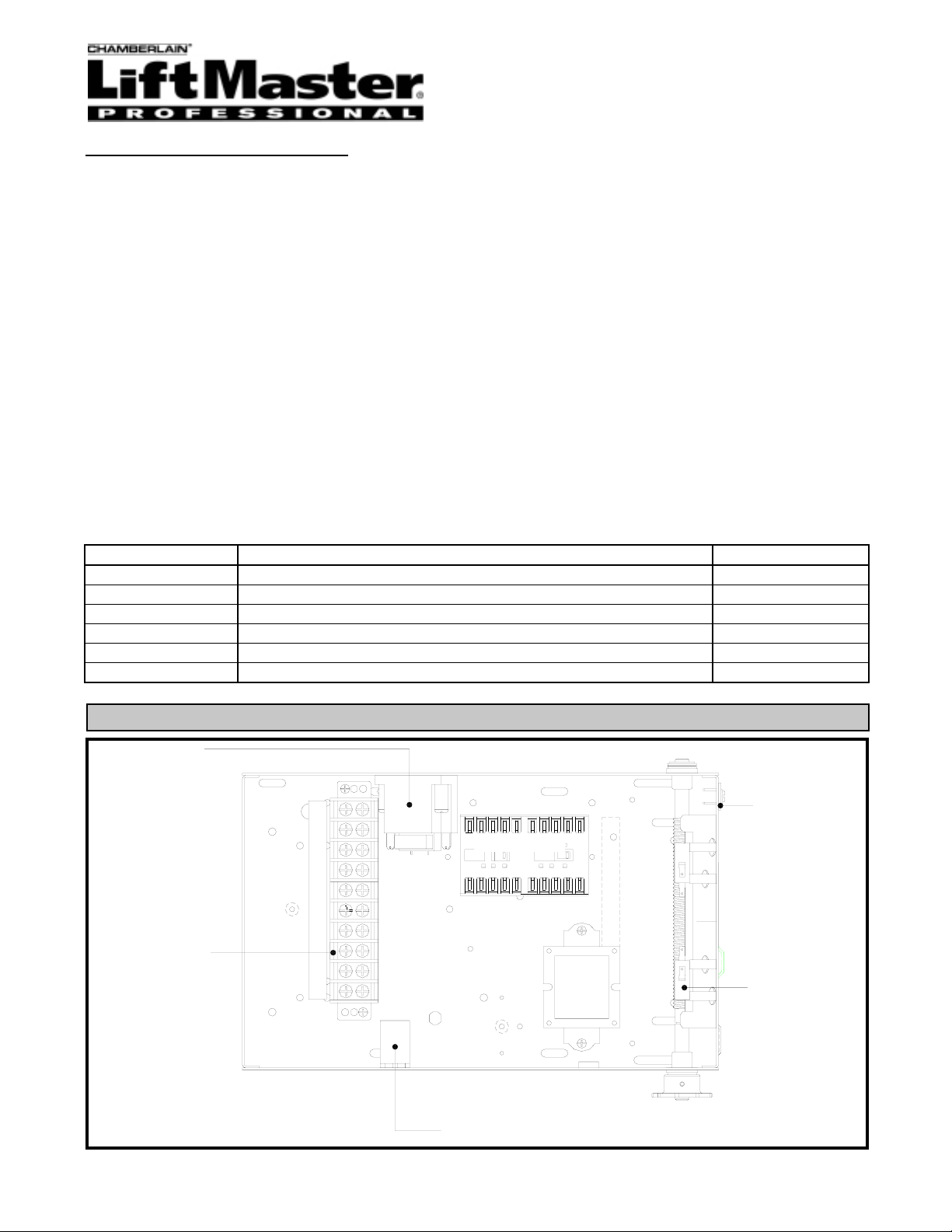
TYPICAL ELECTRICAL BOX LAYOUT
CONTACTOR
XFMR
QUANTITY
1
3
2
2
2
2
RADIO
TERMINAL
BLOCK
(if supplied)
AUX. OPEN
LIMIT SWITCH
R1 RELAY
1
Page 2
INSTALLATION INSTRUCTIONS
WARNING
CAUTION
WARNING
WARNING
WARNING
CAUTION
WARNING
WARNING
1. Disconnect power.
2. The operator must be set to B2 wiring, see wiring
diagram supplied with operator to see correct B2
wiring, if it does not have the appropriate wiring
please consult the factory. This kit is not for MT, MJ
or MH operators.
3. Locate holes and install timer on side wall of
electrical box as shown in electrical box layout.
4. Use the purple wires to connect the timer as
follows:
a. Connect one side of the timer to terminal #2.
b. Connect other side of timer to terminal #3
(see figure 1)
5. Set the desired time
CAUTION
RADIO RECONFIGURATION
If present we strongly recommend that the radio
terminal strip be changed so that if a radio is used it
can OPEN and/or RESET the timer rather than
OPEN and CLOSE. This prevents accidental closing
of the door when someone pushes the transmitter at
the wrong time.
1 Trace the yellow wire from the R2 terminal on the
radio strip (if supplied) to terminal #7.
2. Move this yellow wire from terminal #7 to terminal
#1 (see figure 3).
NOTE:
If reconfigured, users of the radio can be told that if
they are not sure when the door will close they can
press the transmitter to reset the timer.
TIMER DEFEAT (optional)
If a timer defeat switch is desired cut either purple
wire and wire in a simple on/off switch.
INSTALL THE CONTROL STATION WHERE THE
DOOR IS VISIBLE, BUT AWAY FROM THE DOOR
AND ITS HARDWARE. IF CONTROL STATION
CANNOT BE INSTALLED WHERE DOOR IS
VISIBLE, OR IF ANY DEVICE OTHER THAN THE
CONTROL IS USED TO ACTIVATE THE DOOR,
REVERSING EDGE MUST BE INSTALLED ON
THE BOTTOM OF THE DOOR.
INSTALL A REVERSING EDGE UNDER THESE
CIRCUMSTANCES MAY RESULT IN SERIOUS
INJURY OR DEATH TO PERSONS TRAPPED
BENEATH THE DOOR.
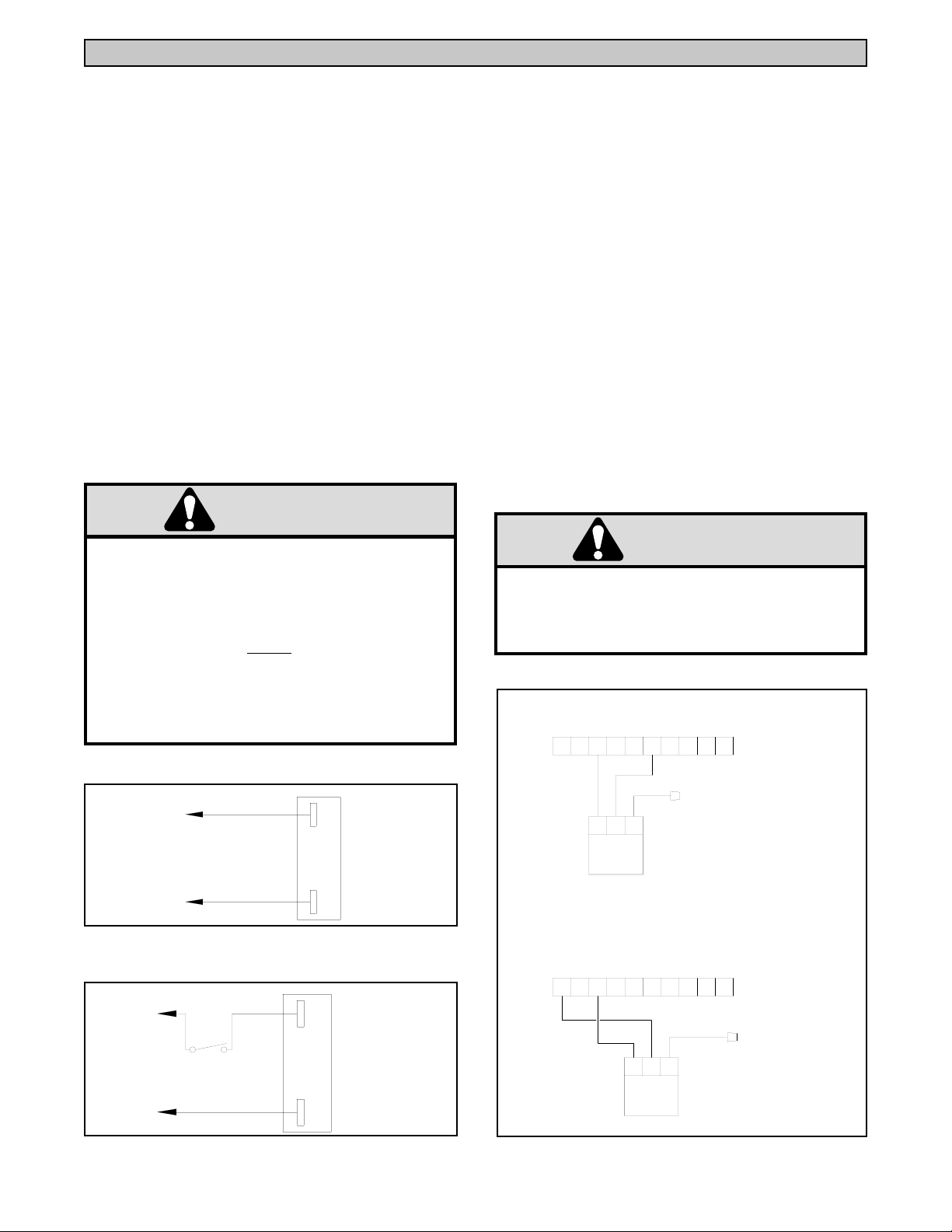
TIMER WIRING (FIGURE 1)
TB #2
TB #3
TIMER DEFEAT WIRING (FIGURE 2)
TB #2
TIMER DEFEAT
TB #3
PURPLE
PURPLE
PURPLE
PURPLE
FAILURE TO
THE TIMER WILL TIME OUT AND CLOSE THE
OPERATOR IF IT IS NOT FULLY CLOSED AND
ALL OPEN AND SAFETY DEVICES ARE
A
CLEARED.
RADIO WIRING
CAUTION
EXISTING CONFIGURATION
1 2 3 4 5 7 10 L1L2 L3
WIRE NUT
IN ELEC. BOX
R1 R2 R3
RADIO
REC’R
SUGGESTED CONFIGURATION
1 2 3 4 5 7 10 L1 L2 L3
WIRE NUT
IN ELEC. BOX
R1 R2 R3
RADIO
REC’R
01-11237A All Rights Reserved
© 1998, The Chamberlain Group, Inc.
 Loading...