

Page 1

APPLICATION REQUIREMENTS:
This wiring conversion is available to models T, GT, J, H, GH, SD, and GSD standard door operator with 24V
control circuits.
The operator must have B2 wiring (see last suffix of part number, ex. T-50-11-B2). If the operator does not
have B2 wiring, conversion kit number 71-B2 must be installed first. contact Link representative for this kit.
TIMER FUNCTIONS:
This wiring kit converts the control circuit of the door operator to function as follows:
1. Timer will close door (after a preset, adjustable interval) when the door is opened from certain or all
devices, but will leave door open when the door is opened by any other means. These devices are
designated by the terminal points to which they are connected.
2. Any device wired to activate the timer (as described above) will also reset the timer to the preset interval
if it is energized during the timing period.
3. An isolated contact will close approximately 10 seconds before the timer closes the door. A light or horn
may be connected to this contact to warn vehicles that the door is about to close. This contact is rated 3
amps at 115VAC. If the power rating of such device exceeds the contact rating, use a relay for interfacing.
4. A timer defeat switch may be used to disable the timer when it is not required.
PACKING LIST:
DESCRIPTION
RELAY, 24VAC, 3PDT
TIMER, DUAL FUNCTION 24V
TY WRAPS
LABEL FOR TERMINAL BLOCK
4 POSITION TERMINAL BLOCK
TINNERMAN NUT
#6-32 X 3/8” SELF TAP SCREW
#6-32 X 1-3/8” PH SCREW
#8-32 X 5/8” PHILLIPS SELF TAP SCREW
#6-32 LOCKNUT
#6 FLATWASHER
WIRE 8” ORANGE .250 SPADE X .187 FASTON (INSULATED)
WIRE, 13” BLACK, 1/4” INSULATED FASTON x .250 SPADE
WIRE, 13” RED, 1/4” INSULATED FASTON x .250 SPADE
WIRE, 13” YELLOW, 1/4” INSULATED FASTON x .250 SPADE
WIRE, 13” BLUE, STRIP x 1/4” INSULATED FASTON
WIRE, 3” BROWN .250 FORK x .250 FORK
WIRE, 12” RED .187 FASTON x .250 FORK (INSULATED FASTON)
WIRE, 24” RED .187 FASTON x .187 FASTON (INSULATED)
WIRE, 12” GREY .187 FASTON x .250 FORK (INSULATED FASTON)
WIRE, 14” BROWN .250 FORK x .250 FORK
WIRE, 27” YELLOW .250 FASTON x .250 FORK
MOV ASSEMBLY FOR USE WITH TIMER KIT
#8-32 SERRATED FLANGE NUT
WIRE 27” BROWN .250 FASTON (INS) X .250 DOUBLE FASTON
QUANTITY
1
1
16
1
2
2
1
1
2
1
2
1
2
1
1
1
1
1
1
1
1
1
1
2
1
PART NUMBER
24-24-6
26-200-1
27-10199
40-10222
42-104
84-ST-06
82-PX-06-06t
82-PX06-19
82-PX08-10T
84-LN-06
85-FW-06
95-OR08-68
95-BK13-69
95-RD13-69
95-YE13-69
95-BL13-19
95-BR03-66
95-RD12-68
95-RD24-88
95-GY12-68
95-BR14-66
95-YE27-46
76-29V30500
84-FN-08
95-BR27-9G
Timer Kit
Used For 90-T1 and 90-T2
WIRING CONVERSIONS
Page 2
2
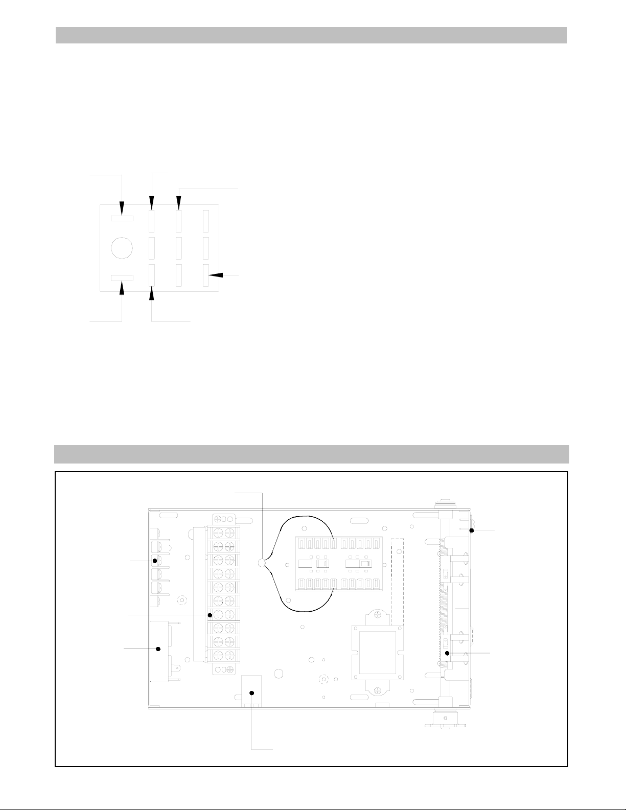
INSTALLATION INSTRUCTIONS
1. COMPONENT MOUNTING
Familiarize yourself with the component layout in the electrical box of the operator and the new parts included
with this kit. It is recommended that components not be mounted until the modification is complete.
a. Locate the existing R1 RELAY (DPDT) on the side
wall of the electrical box and remove. Replace with the
new R1 RELAY (3PDT) and reconnect the wires as
shown in this figure.
b. Mount the TIMER on back wall across from the
terminal block using #6-32 x 1-3/8” pan head screw. Be
sure to leave timer adjustment knob at top where it’s
accessible.
NOTE: On single phase operators it may be necessary
to reposition the instant reverse (IR) relay to the
opposite wall to clear terminal block and timer.
c. Mount the 4 position TERMINAL BLOCK on the back
wall above the 10 position terminal block, use the holes
that are 1” from the top lip of the box. Use (2) #10-32 x
5/8” long self tapping screws to secure in place. Align
and install terminal markers. Refer to electrical box
layout below for location of components in the box.
TYPICAL ELECTRICAL BOX LAYOUT
RED
RED
ORANGE
ORANGE
PURPLE
PURPLE
NEW R1 RELAY
(wires from old R1 relay)
COIL
4 POLE
TERMINAL
BLOCK
10 POLE
TERMINAL
BLOCK
TIMER
R1 RELAY (3PDT)
AUX. OPEN
LIMIT SWITCH
RADIO
TERMINAL
BLOCK
(if supplied)
L3
L2
L110123457
CONTACTOR
XFMR
MOV
A1
A2
NOTE: Before you start modification, test all operator functions, then disconnect power.
Page 3

3
a. Cut existing wire ties in box to accommodate
modification. Be carful not to skin any wires that are
in the box.
b. Determine which limit switch is the open auxiliary
switch and remove all three wires (yellow, orange and
purple) from the switch and the terminals they are
attached to, discard wires.
c. From the new R1 relay remove the red wire (that
goes from coil of the relay to the R3 terminal on 3
position radio block) from the coil of the relay and
install on common of the auxiliary open limit switch.
d. From the new R1 relay install a new 24” red wire
from the coil to the normally closed on the auxiliary
open limit switch.
e. From the new R1 relay remove red wire from coil
that goes to terminal #1 and discard wire.
f. From the new R1 relay connect new 12” red wire
from coil to terminal #11.
g. Move the grey wire from terminal #1 to terminal
#11.
h. Move the orange wire from terminal #7 to terminal
#1.
i. On timer locate the brown & orange double
connected wire. Install the orange wire on third
common on new R1 relay. Install the brown wire on
R1 of the 3 position radio block.
2. WIRING CONNECTIONS
Refer to the illustrations and instructions describe below to wire new components. NOTE: If a residential radio is
wired to the operator to open and close door, the receiver must be re-wired to open only (see diagram below).
j. Install the 12” grey wire to the normally open on the
new R1 relay that corresponds to the orange wire in
step (i) and connect to terminal #11.
k. Install the 3” brown jumper wire between terminals
#11 and #12 (if timer defeat switch is going to be
used put switch in place of brown jumper wire).
l. Install the 13” blue wire from the #3 on the timer to
the orange wire nut.
m. Install the 13” yellow wire from #5 on the timer to
terminal #12.
n. Install the 13” red wire from #1 on the timer to
terminal #2.
o. Install the 13” black wire from #6 on the timer to
terminal #14.
p. Install the 13” black wire from #7 on the timer to
terminal #13.
q. Locate MOV (Metal Oxide Varsitor #76-29V30500)
this looks like two orange wires with black heat shrink
tubing and install from A1 to A2 on the open contactor
coil (see figure on pg. 2).
r. For Timing Only! For “T1” type wiring install the
14” brown jumper between terminals #1 an #11.
Refer to control wiring features on back page to
determine desired wiring type.
3. To utilize radio receiver block (R1, R2 and R3):
a. If open and a start timer is not desired move the
yellow wire from terminal #7 to terminal #1.
b. If open and start timer is desired. Remove the
yellow wire that connects terminal #7 to R2 on the
radio receiver and discard. Install the 27” yellow wire
from R2 radio receiver to terminal #11.
(RED)
(PURPLE)
(PURPLE)
(ORANGE)
(ORANGE)
(ORANGE)
(RED)
(GREY)
T.B. #11
CONTACTOR - CLOSED (14)
CONTACTOR - CLOSED (A2)
T.B. #11
#2 TIMER
T.B. #3
T.B. #1
AUX. LIMIT SW. (NC)
COIL
(BLACK)
(BLACK)
(YELLOW)
(BLUE)
(BROWN)
(RED)
2
1
6
7
3
5
T.B. #2
T.B. #13
R1 RADIO REC’R
WIRE NUT
T.B. #12
T.B. #14
WIRE NUT
IN ELEC. BOX
R3
R2
R1
RADIO
REC’R
EXISTING
RADIO CONTROL
TERMINAL BLOCK
WIRE NUT
T.B. #7
T.B. #3
CHANGE THIS
CHANGE THIS
TO THIS
-OR-
RESIDENTIAL RADIO re-wired to open only.
TIMER
NEW R1 RELAY (3PDT)
1 2 3 4 5 6 7
WIRE NUT
IN ELEC. BOX
R3
R2
R1
RADIO
REC’R
1 2 3 4 5 6 7
TO THIS
1 2 3 4
R3
R2
R1
R3
R2
R1
R3
R2
R1
R3
R2
R1
EXISTING
RADIO CONTROL
TERMINAL BLOCK
WIRE NUT
T.B. #11
T.B. #3
RADIO
REC’R
RADIO
REC’R
(ORANGE)
3 COMMON R1 RELAY
TO OPEN
ONLY
TO OPEN &
START TIME
Page 4

CONTROL FEATURES NOTES:
1. OPEN control may be any number of the following
devices wired in parallel: push-button, key switch,
pull switch, card reader, digital key, vehicle loop
detector, photo beam, telephone entry control, or
other similar device.
2. SAFETY device may be any number of the
following devices wired in parallel: pneumatic door
edge, electric door edge, photo beam, motion
detector, or other similar device.
3. Audible/visible Warning device may be light,
strobe, horn, buzzer, or other simular device.
Separate power source is required.
CONTROL WIRING OPTIONS
3. DEVICE CONNECTIONS:
Refer to the chart to determine the available control features for T1 and T2 wiring. Connect control and safety
devices as shown in figures below. NOTE: We recommend the use of gauge or heavier wire for all control circuit
wiring.
CONTROL FEATURES
WIRING TYPE
T1 T2
OPEN control (1)
requiring only momentary contact
CLOSE button
requiring only momentary contact
STOP button
requiring momentary contact
RADIO RECEIVER
to open only (24VAC, 3-screw mount)
EXTERNAL INTERLOCK switch
to open only (24VAC, 3-screw mount)
Safety Device (2)
to REVERSE while closing
Audible/Visible Warning Device (3)
on 10 sec. before closing the timer
REVERSE
(if closing)
with momentary contact on OPEN control
AUTOMATIC TIMER
closes when
door is open from any device
AUTOMATIC TIMER
closes when
door is open from selected devices
T1 CONTROL WIRING
115V
POWER
TIMER DEFEAT SWITCH
OPEN WITH TIMED CLOSING
CLOSE
*STOP
EXTERNAL INTERLOCK
SAFETY EDGE
1O
POWER
IN
3O
POWER
IN
**
**
WARNING LIGHT
ON OFF
14
13
11
12
1
2
4
3
5
7
L1
10
L2
L3
NOTES:
* If no STOP button is used, provide a jumper (2 instances) between
terminals 3 and 4.
** Remove jumper when External Interlock switch is used.
1) Timer will close door (after preset, adjustable interval) when door is
opened from any device connected to either terminal #1 or #11
OPEN WITH TIMED CLOSING
© 1998, The Chamberlain Group, Inc.
01-11236E All Rights Reserved
T2 CONTROL WIRING
115V
POWER
TIMER DEFEAT SWITCH
OPEN WITH TIMED CLOSING
CLOSE
*STOP
EXTERNAL INTERLOCK
SAFETY EDGE
1O
POWER
IN
3O
POWER
IN
oo
**
WARNING LIGHT
ON OFF
14
13
11
12
1
2
4
3
5
7
L1
10
L2
L3
OPEN#2
NOTES:
* If no STOP button is used, provide a jumper (2 instances) between
terminals 3 and 4.
** Remove jumper when switch is used.
oo Remove jumper when timer defeat switch is used.
1) Timer will close door (after preset, adjustable interval) when door is
opened from any device connected to either terminal #1 or #11.
2) If constant pressure to open is desired for devices connected to terminal
#1, remove yellow wire from terminal #3 and place on #1.
 Loading...