

Page 1
T WIRING TYPE
MODIFICATION
Models: T, GT, J, H, GH, SD, and GSD
APPLICATION REQUIREMENTS:
This wiring modification is available to models T, GT, J, H, GH, SD and GSD standard door operator
with 24VAC line voltage. Not for use with Logic Control Board.
FUNCTIONS:
Momentary contact to open, close and stop, with open override and Timer-to-Close. OPEN button may
be connected to activate timer if desired. Auxiliary controls may be connected to open and activate
Timer-to-Close, or to open and close without activating timer. If a timer has been activated, all opening
devices will recycle timer. Includes wiring for sensing devices to reverse but not reactivate timer.
PREP
ARATION:
Unpack kit to verify the parts listed below are included. Refer to installation instructions on reverse
side.
PACKING LIST
PART NUMBER
01-12414
14-10198
24-24-1
26-438
27-10199
27-8002-K
31-11119
40-10222
42-103
74-12415
82-PX06-06T
82-PX06-16
82-WX10-08T
84-LH-06
84-ST-06
DESCRIPTION
T WIRING INSTRUCTIONS
PLASTIC BAG, 16” X 12” X 4 MILL.
RELAY 24VAC COIL DPDT
ARTISAN TIMER
5-1/2” CABLE TIE
AUXILIARY CONTACT BLOCK
SPACER
LABEL, 4 POSITION TERMINAL BLOCK
3 POSITION TERMINAL BLOCK
“T” WIRING, R2 AND R3 WIRING ASSEMBLY
SCREW, #6-32 X 3/8” PAN HD PHILLIPS SELF TAP
SCREW, #6-32 X 1” PAN HD PHILLIPS
SCREW, #10-32 X 1/2” HEX WASHER SELF TAP
#6-32 LOCK HEX NUT
#6-32 TINNERMAN NUT (SINGLE)
QUANTITY
1
1
2
1
4
1
2
1
1
1
4
2
2
2
4
95-PU07-69
95-BR03-66
95-BL10-16
*1262-1
**1262-3
* = 1 Phase Operators Only
** = 3 Phase Operators Only
WIRE 18GA. PURPLE 7”, .250 FORK X .250 INSUL. FASTON
WIRE 18GA. BROWN 3”, .250 FORK X .250 FORK
WIRE 18GA. BLUE 10”, .250 FORK X STRIP
“T” WIRING DIAGRAM 1 PHASE
“T” WIRING DIAGRAM 3 PHASE
2
1
1
1
1
Page 2
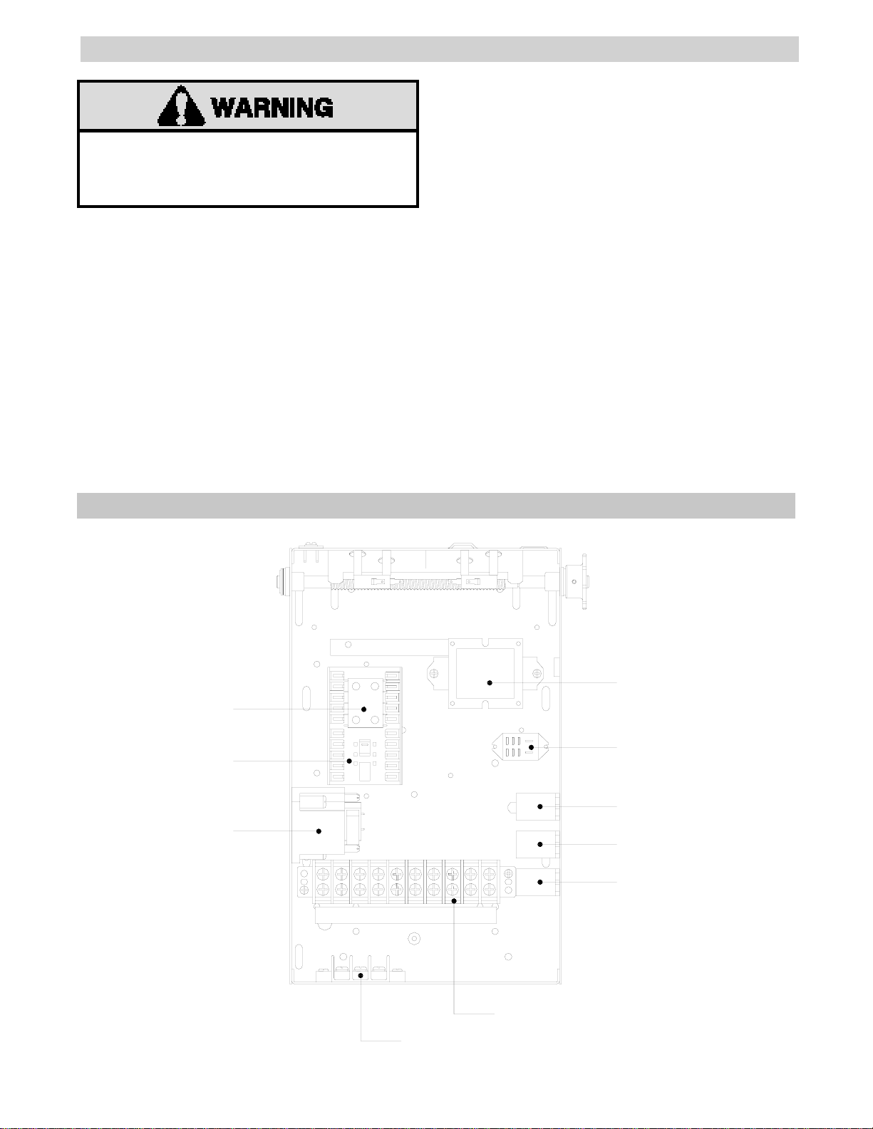
COMPONENT MOUNTING
TO AVOID SERIOUS PERSONAL INJURY OR DEATH
FROM ELECTROCUTION, DISCONNECT ELECTRIC
POWER TO OPERATOR BEFORE INSTALLING “T”
WIRING MODIFICATION.
1. For additional help during any of the following
steps refer to the electrical box layout on the bottom
of the page.
2. Remove the (IR) Relay from the wall of the
electrical box (this is the relay closest to the terminal
block) and reattach on the floor of the electrical box
next to the (R1) Relay. Use old hardware to secure in
place.
3. Install the two new relays in the electrical box.
Mount one of the relays in the holes where the relay
from step two was just removed and the other relay in
the existing holes right next to it.
Use (4) #6-32 x 3/8” long self tapping pan head
screws and (4) #6-32 tinnerman nuts supplied to
secure in place. Be sure when mounting relays to
mount them coil side out.
4. Install the new four position terminal block on the
the back wall of the electrical box above the 10
position terminal block, use the holes that are 1” from
the lid of the box. Use (2) #8-32 x 1/2” self tapping
hex head screws supplied to secure in place. Label it
11, 12, 13 with the new label supplied.
5. Install the new timer to the side wall of the
electrical box, this is the side opposite the relays.
Use (2) #6-32 x 1” long pan head screws, (2)
standoffs and (2) #6-32 locknuts to secure in place.
6. Install the new auxiliary contact block on the
closed side of the contactor, this is the half nearest
the limit switches and has purple wires on the coils.
NEW AUXILIARY
CONTACT BLOCK
CONTACTOR
NEW TIMER
TYPICAL ELECTRICAL BOX LAYOUT
TRANSFORMER
(IR) RELAY
R1 RELAY
NEW R2 RELAY
NEW R3 RELAY
10 POLE TERMINAL BLOCK
NEW 3 POLE TERMINAL BLOCK
1
Page 3

WIRING INSTRUCTIONS
1. For additional help during any of the following
steps refer to the wiring diagram on the bottom of the
page.
2. Connect the blue wire running from the (NO) on
the R2 relay to terminal #3 on the ten position
terminal block.
3. Connect the orange wire running from the (C) on
the R2 relay to terminal #1 on the ten position
terminal block.
4. Connect the yellow wire running from the (COIL)
on the R2 relay to terminal #11 on the new terminal
block.
5. Connect the yellow wire running from the (COIL)
on the R2 relay to #62 on the auxiliary contact block.
WIRING DIAGRAM
6. Connect the yellow wire running from the (COIL)
on the R3 relay to #61 on the auxiliary contact block.
7. Connect the purple wire running from the (C) on
the R3 relay to terminal #12 on the new terminal
block.
8. Connect a new purple wire from the timer to
terminal #13 on the new terminal block.
9. Connect a new purple wire from the timer to
terminal #2 on the ten position terminal block.
10. Connect a new brown wire from terminal #12 on
the new terminal block to terminal #13 on the new
terminal block.
11. Connect a new blue wire from #62 on the
auxiliary contact block to the existing wire nut.
R2 RELAY
R3 RELAY
NC
NC
BL
NO
BL
NO
TERMINAL 3
TERMINAL 1
OR
COIL
C
BL
COIL
C
PU
YE
YE
YE
TERMINAL 11 (NEW)
AUXILIARY
CONTACT
BLOCK
62
61
54
53
EXISTING
WIRE NUT
EXISTING
WIRES
BL
TERMINAL
12 (NEW)
TERMINAL
13 (NEW)
2
PUBR
TIMER TO
CLOSE
PU
TERMINAL 2
Page 4

WILL SET TIMER
WILL NOT SET TIMER
CONTROL DEVICE CONNECTIONS
11 3
1 3 7 3
TIMER DEFEAT
12 13
01-12414A All Rights Reserved
© 1998, The Chamberlain Group, Inc.
 Loading...