

Page 1
APPLICATION
This modification is available to Model T, GT, J, H, GH, GSD and SD standard door operators with 24V control circuits (M).
Required for use with 4-wire “fail-safe” type electrical edges.
NOTE: For operators with logic control board (L), use the CPSII commercial protector system II.
F2 WIRING TYPE (K-LINE
OPERATORS) CONVERSION
90F2 FOR MODELS: T, GT, J, H, GH, SD, GSD
WIRING
1. Disconnect power to operator.
2. Position door in mid-position, set limit nuts so that both
open and close limits switches are depressed (listen for
click).
3. Connect the diode (provided in operator box) to the two
wires of the four wire safety edge as shown. The polarity
must be correct for the fail safe circuit to function.
4. Connect the remaining two leads of the safety edge to
terminals 3 and 10 as shown.
5. Restore power to operator.
6. Refer to the two test lights built into the fail safe circuit
board in the control box.
• If red light flashes, reverse connections terminal 3 and
10.
• If both red and green flash, the diode is connected
improperly. Check connections.
• If green light only is on, connections are correct.
Proceed with limit switch adjustment per owner's
manual.
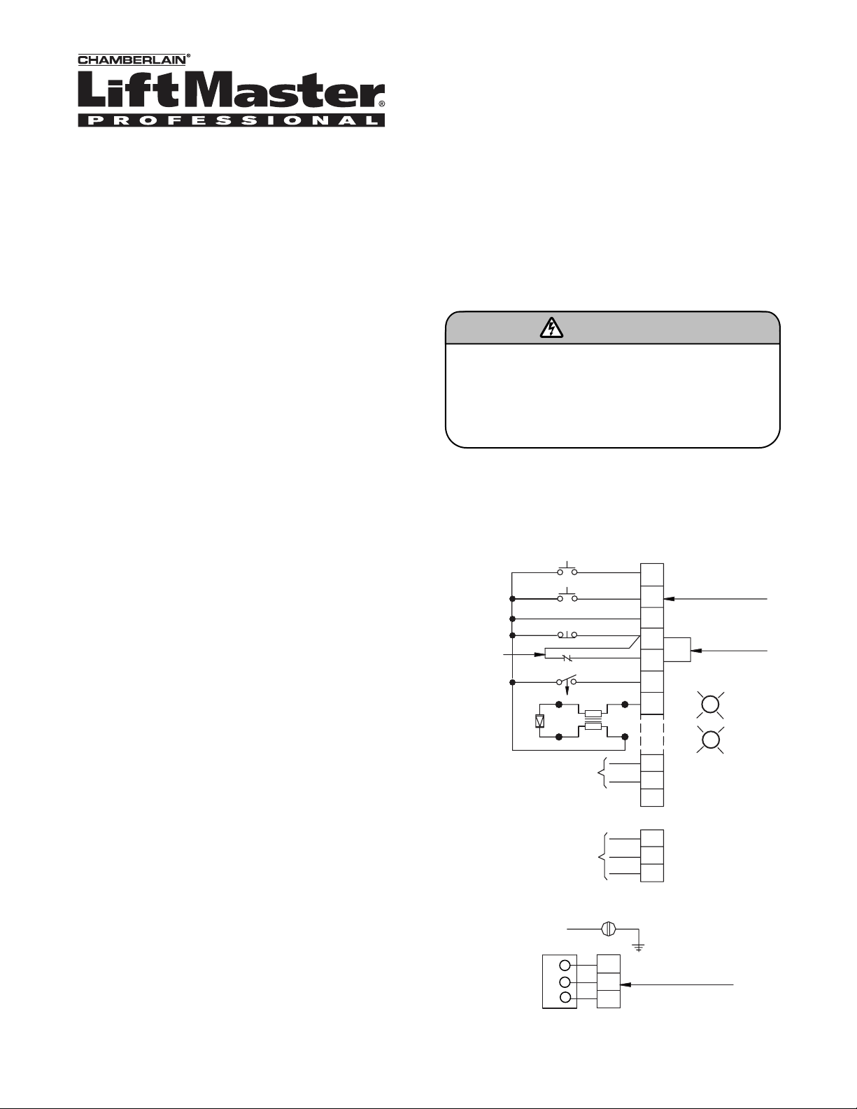
FIELD WIRING
To prevent possible SERIOUS INJURY or DEATH from
electrocution, disconnect electric power to operator
BEFORE installing.
ALL electrical connections MUST be made by a qualified
individual.
WARNING
NOTE: The door will not close if safety edge or wiring is
damaged. Do not apply power until after reading fail safe
safety instructions.
OPEN
1
TERMINAL BLOCK
2
3
4
5
7
10
L1
L2
L3
REMOVE JUMPER
WHEN EXTERNAL
SWITCH IS USED.
O.K.
G
R
N.G.
TEST
LIGHTS
EXTERNAL
INTERLOCK
FAIL - SAFE
SAFETY EDGE
CLOSE
STOP
TO OPEN AND CLOSE
R
DIODE
BL
1 PHASE
POWER IN
GROUND
RADIO
RECEIVER
3 PHASE
POWER IN
3
2
1
L1
L2
L3
R3
R2
R1
(OPTIONAL)
AUX. TERMINAL BLOCK
Page 2
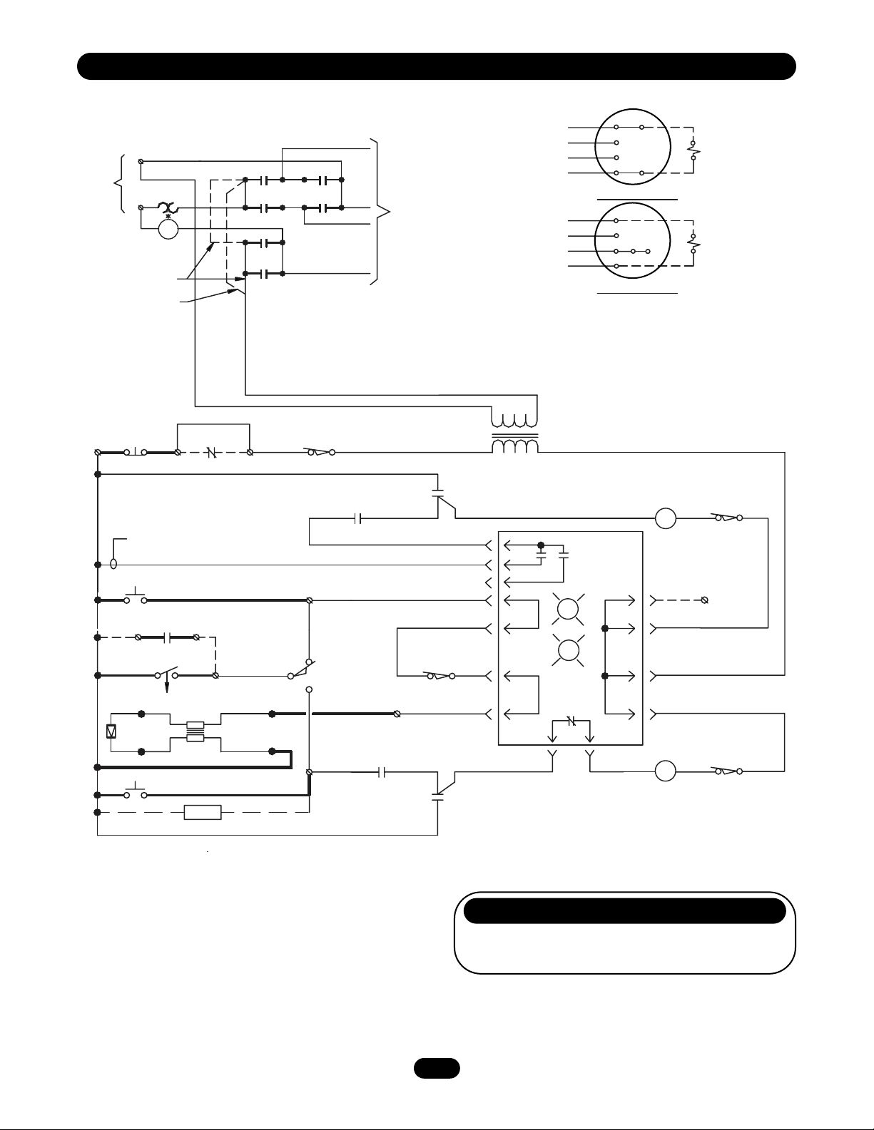
*I.R. COIL VOLTAGE IS THE
2
NOTES:
1. I.R. (Instant Reverse) relay is wired normally open and
is held closed when motor is not running.
2. Terminals R1, R2, and R3 are on optional external
terminal block.
3. Optional timer to close will, after preset time, close the
door whenever it is not fully closed and all open and
safety devices are cleared.
4. We recommend the use of 16 gauge or heavier wire for
all control circuit wiring.
REPLACEMENT PARTS
Fail Safe Board P/N 7129505
Diode P/N 2940051
1 PHASE F2 WIRING- 0192
SAME AS THE LINE VOLTAGE.
W
L2
O/L
BK
POWER IN
L1
115V. ONLY
230V. ONLY
BK
BK BK
I.R.
3PDT.
GY
CL
4
4OP31
OP
2
CL
6
OP
3
1
5
6
5
CL
2
BL
P
Y
TO
MOTOR
INTERCHANGE PURPLE & GRAY WIRES.
3
P
BL
Y
GY
P
BL
Y
GY
TO REVERSE MOTOR DIRECTION,
1
8
5
4
115V. CONNECTION
1
8
523
4
230V. CONNECTION
BK-BK
2
BK-BK
BK-BK
BK-BK
SOLENOID
115V. BRAKE
(WHEN REQUIRED)
SOLENOID
230V. BRAKE
(WHEN REQUIRED)
STOP
3
Y
FOR DELAY ON REVERSE MOVE TO 3d
OPEN
OPEN AND CLOSE
R1
OR
AND CLOSE
R
DIODE
BL
CLOSE
INTERLOCK
4
RADIO TO
R2
TO OPEN
4 WIRE
FAILSAFE EDGE
Y
TIMER
(OPTIONAL)
Y
7
EXTERNAL
BR
W
5
Y
(WHEN PROVIDED)
Y
Y
HAND CHAIN
SWITCH
OR
OR
1
OR
OR
N.C.
AUX OPEN L/S
N.O.
C
P
2
R
BR
PRI.
F1
TEST
LIGHTS
6
Y
G
O.K.
N.G.
R
F2
OR
OP
A1
P.C. BOARD
8
7
PP
CL
A2
R
OR
Y
P
A1
OR
A2
OPEN
N.C.
R3
CLOSE L/S
N.C.
LS
P
C
P
C
Y
24 VAC.
14
OP
IR
IR
P
13
Y
OR
AUX. CLOSE L/S
GY
N.C.
10
GY
RP
GY
C
14
CL
13
SEC.
1
3i
3d
9
9
10
10
Page 3

3
3 PHASE F2 WIRING - 193
NOTE: Terminals R1, R2 and R3 are on optional external terminal block.
O/L (WHEN PROVIDED)
BK
L2
BK
L1
POWER IN
BK
L1
BR
STOP
3
Y
FOR DELAY ON REVERSE MOVE TO 3d
OPEN
RADIO TO
OPEN AND CLOSE
R1
OR
TO OPEN
AND CLOSE
FAILSAFE EDGE
R
DIODE
BL
CLOSE
CL
4
OP
4
OP
2
CL
6
EXTERNAL
INTERLOCK
4
R2
7
4 WIRE
3
3
1
5
Y
GY
OP
6
5
CL
2
1
P
Y
BR
BR
HAND CHAIN
Y OR BR
5
SWITCH
(WHEN PROVIDED)
1
OR
Y
C
P
2
TO
MOTOR
BR
Y
OR
OR
OR
N.C.
AUX. OPEN L/S
N.O.
24
P
R
MOTOR O/L
OR
O/L PILOT
14
13
AUX. CLOSE L/S
GY
N.C.
10
GY
BL
14
13
Y OR BR
OP
OR
CL
GY
1
7
BR
P
BR
BR
BR
PRI.
24 VAC.
SEC.
3d
9
GY
C
10
P
2
Y
3
208V./230V. CONNECTION
GY
1
P
2
Y
3
460V. CONNECTION
TO REVERSE MOTOR DIRECTION,
INTERCHANGE ANY TWO INCOMING
POWER LEADS AT TERMINAL STRIP.
Y
1
F1
3i
TEST
LIGHTS
6
G
R
F2
9
10
4
8
5
9
6JJ
4
7
8
9
P.C. BOARD
O.K.
N.G.
J
5
6
J
OR
A1
8R
7
P
A2
BL-BK
O/L (WHEN REQ’D)
(UP TO 3/4 HP)
BL-BK
BL-BK
(WHEN REQ’D)
O/L
(UP TO 3/4 HP)
BL-BK
OPEN L/S
OR
OP
A2
N.C.
R3
OR
Y
P
CLOSE L/S
P
CL
A1
N.C.
C
C
SOLENOID
230V. BRAKE
(WHEN REQUIRED)
SOLENOID
230V. BRAKE
(WHEN REQUIRED)
OR
P
Page 4

© 2006, The Chamberlain Group, Inc.
01-13410B All Rights Reserved
 Loading...