

Page 1
E2 Wiring Type (K-Line Operators)
WARNING
CONVERSION INSTRUCTIONS
SINGLE PHASE MODELS: T, GT, J, H, GH, SD, GSD
Instructions to convert a single phase standard control box with type C2 / B2 control
wiring to type E2 control wiring
Type E2 wiring Function: Constant pressure is required on the close button, if a close button
is released before the door is fully closed the door will return to open position. Use of a safety
edge will allow you to override close button. A single button to open and close cannot be used.
Packing List:
PART NUMBER
75-12480
82-PX08-04T
95-GY18-33
95-GY18-36
LIMIT SWITCH BRACKET ASSEMBLY
SCREW, #8-32 x 1/4” LONG PAN HEAD PHILLIPS
WIRE, 18GA. GRAY 18”, 3/16 FASTON x 3/16 FASTON
WIRE, 18GA. GRAY 18”, 3/16 FASTON x 1/4 FORK
DESCRIPTION
INSTALLATION INSTRUCTIONS
NOTE: Before you start modification, test all
operator functions, then disconnect power.
1. Locate the auxiliary open limit switch with three
wires (on back wall of electrical box). Remove the
switch and all three wires (orange from terminal one,
purple from terminal two and yellow from terminal
seven) and discard.
2. Locate the R1 relay (24VAC relay with six wires).
Remove the two orange wires (one from terminal
three and one from terminal seven) and discard.
3. Locate the external radio strip and remove one
orange wire going from “R1” to terminal #3 and
discard wire. Remove one yellow wire going from
“R2” to terminal #7 and discard.
QUANTITY
1
2
1
1
WARNING
Disconnect power to the operator(s) before
making control wiring modification.
Be sure to adjust bracket so limit nut will actuate
switch in passing, this will be the roll back switch
(refer to figure 1).
8. Install a new grey wire from terminal #10 to the
normally closed on the roll back switch. Install
another grey wire from the common on the roll back
switch to the coil of the (R1) relay were the red wire
was removed in step 6.
NOTE: Be sure to leave 2 red wires on “R3” radio
block intact.
4. Move red wire from terminal three to terminal two.
5. Move gray wire from terminal ten to terminal three.
6. Locate the (R1) relay (see step two). Remove the
red wire connecting terminal one and coil of (R1)
relay and discard.
NOTE: Be sure to remove wire going to terminal #1
not terminal “R3” on radio block.
7. Install new bracket and limit switch with hardware
supplied.
9. Test unit. Remember if unit is not fully closed it
will run open as soon as power is applied. Fine tune
roll back switch to turn off roll back features just as
the close limit turns off contactor.
10. If no stop button is used, provide jumper between
terminals three an four.
11. Leave limit nuts spread far apart for very short
door travel. This will insure electrician won’t damage
door when he applies power to unit.
NOTE: For additional help with the wiring described
above, refer to the schematic diagram on page two of
the instructions.
Page 2
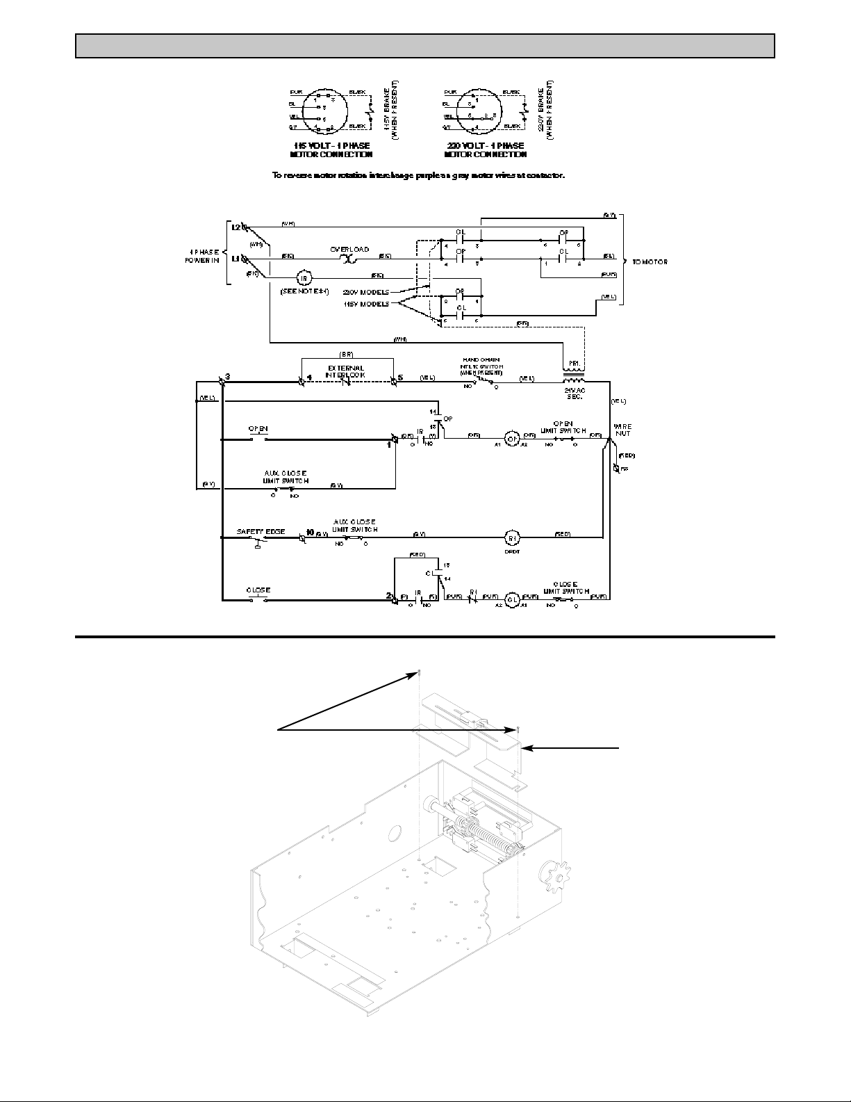
E2 SCHEMATIC DIAGRAM
(2) #8-32 X 1/4” LONG PAN
HD PHILLIPS SELF TAPING
SCREWS
© 1998, The Chamberlain Group, Inc.
01-11971B All Rights Reserved
FIGURE 1
ROLL BACK SWITCH
BRACKET ASSEMBLY
 Loading...