

Page 1
VARIABLE SPEED
MODIFICATION ADDENDUM
MODELS: GH & GT (1/2 - 1HP, 1PH. ONLY)
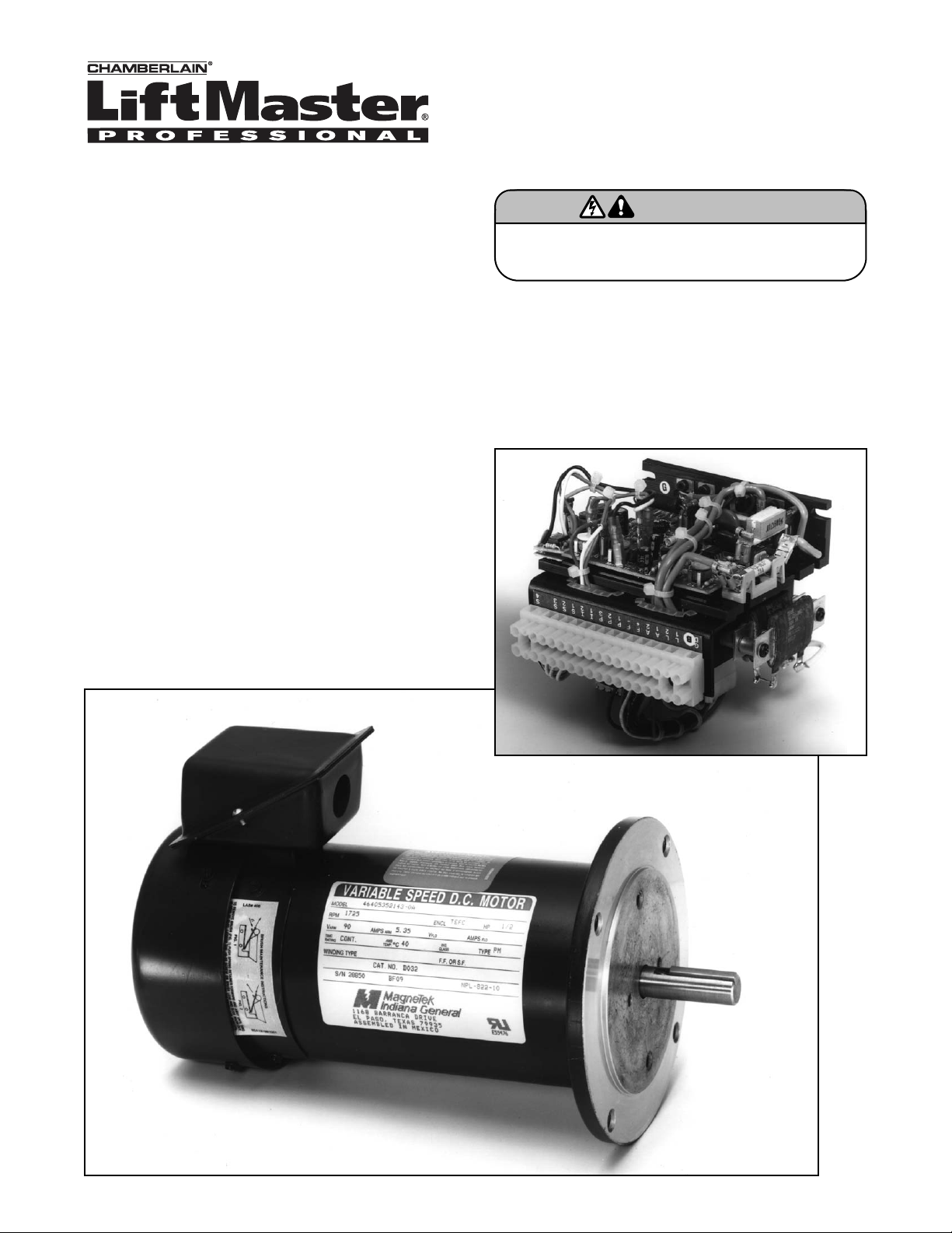
Variable Speed DC Motor
DC Controller
Safety equipment MUST be used with operators
employing this modification.
WARNING
WARNING
APPLICATION
This operator is equipped with a variable speed
modification. The AC motor and control circuit in a door
operator has been replaced with a DC variable speed drive
control and permanent magnet DC motor. May be provided
for either 115 or 230VAC single phase power. Allows
adjustment of the door speed over a wide range, up to 4
ft/sec on some applications. Acceleration adjustment gives
“ramp up”, or soft starts to allow operation of very heavy
doors. Dynamic brake and current limit circuits replace
mechanical brake and clutch respectively, minimizing the
number of moving parts that may wear out. Suitable for
continuous duty and high cycling applications.
Refer to the wiring diagram included with this addendum in
lieu of diagrams included with owner's manual.
VARIABLE SPEED WITH DECELERATION (OPTIONAL)
PART NUMBER: 90-827
When present, provides a adjustable “ramp down” or soft
stop at the full open and full close position.
NOTE: This modification will usually affect the horsepower
selection for a given model. Higher speeds require higher
horsepower for the same door. If you have concerns,
consult your representative for specific horsepower rating
information on your application.
Page 2
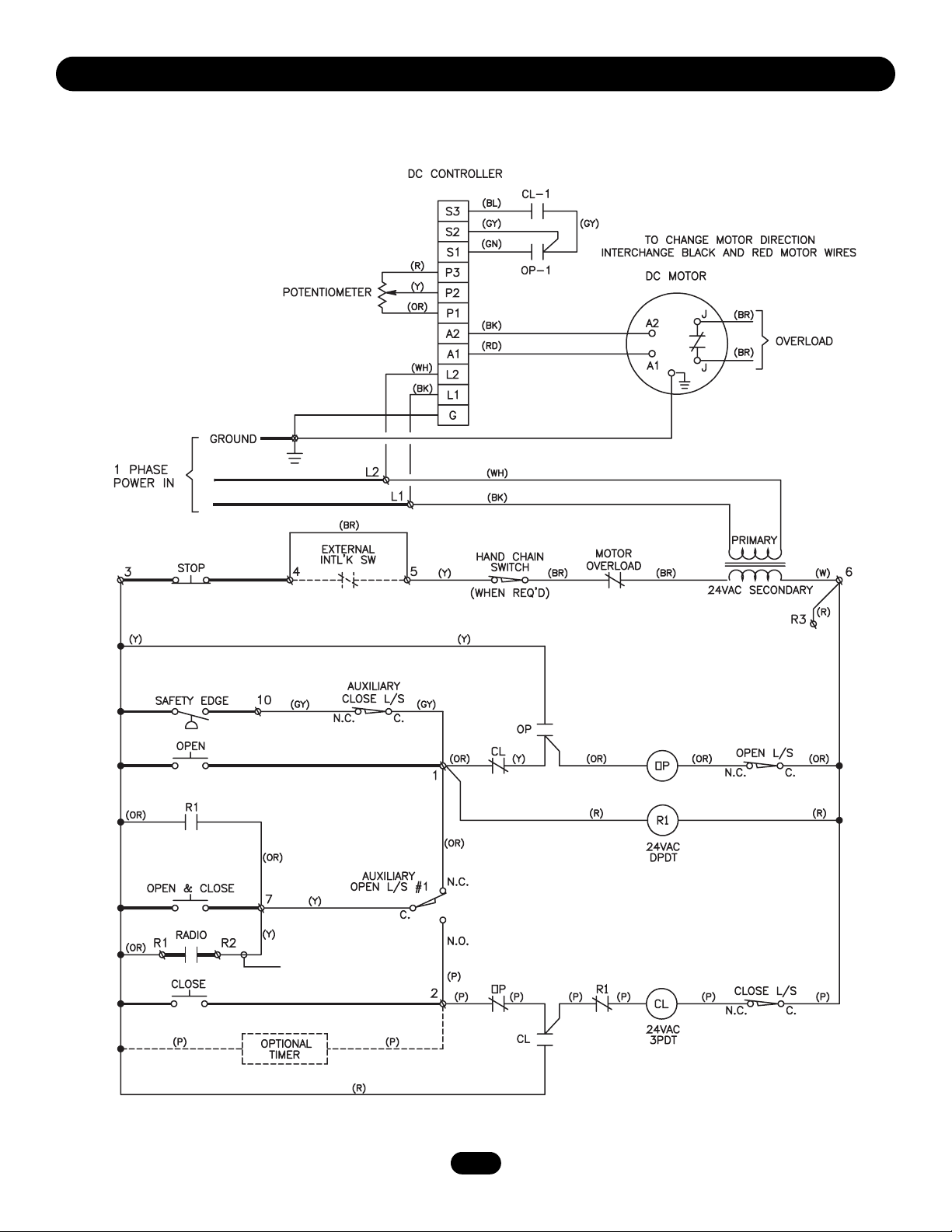
VARIABLE SPEED MODIFICATION
SCHEMATIC DIAGRAM
1211
2
SEE NOTE
NOTE: When equipped with a Timer to Close the yellow wire will connect from terminal R2 to terminal 1
and the radio will only open and set the timer.
Page 3

1639
VARIABLE SPEED MODIFICATION WITH
OPTIONAL DECELERATION (P/N 90-827)
SCHEMATIC DIAGRAM
3
SEE NOTE
NOTE: When equipped with a Timer to Close the yellow wire will connect from terminal R2 to terminal 1
and the radio will only open and set the timer.
Page 4

© 2006, The Chamberlain Group, Inc.
01-12437B All Rights Reserved
CONTROL CONNECTION DIAGRAM
IMPORTANT NOTES:
1. The 3-button control station provided must be
connected for operation.
2. If a STOP button is not used, a jumper must be placed
between terminals 3 and 4.
3. Auxiliary control equipment may be any normally open
two wire device such as pull switch, single button, loop
detector, card key or such device.
4. Use 16 gauge or heavier wire for all control circuit wiring.
3-BUTTON STATION or 3 POSITION KEYSWITCH w/ SPRING RETURN TO CENTER AND STOP BUTTON
STANDARD
1234
Open
Close
Stop
ALL WIRING TYPES
2 BUTTON STATION or 3 POSITION KEY SWITCH w/ SPRING RETURN TO CENTER
STANDARD
124
Open
Close
ALL WIRING TYPES
124
Open
Close
ALL WIRING TYPES
2 OR MORE
1234
Open
Close
Stop
2 OR MORE
Open
Close
Open
Close
Stop
SEE NOTE #2SEE NOTE #2 SEE NOTES
KEY LOCKOUT
1
234
Open
Close
Stop
KEY SWITCH
ALL WIRING TYPESALL WIRING TYPES
1 BUTTON STATION or
ANY AUXILIARY DEVICE
3
7
#2 AND #3
OPEN / CLOSE
B2 or T1
WIRING TYPES ONLY
SENSING DEVICE TO REVERSE OR STOP
3
10
SENSING DEVICE
ALL WIRING TYPES
EXTERNAL INTERLOCK
REMOVE JUMPER
WHEN INTERLOCK IS USED
4
5
ONE
ALL WIRING TYPES
4
2 OR MORE
5
RESIDENTIAL RADIO CONTROLS
OPEN TIMER TO CLOSE
**
R2
R1
RADIO CONTROL
ALL WIRING TYPES
T1 WIRING - RADIO TO OPEN ONLY
**
R3
EXTERNAL
TERMINAL BLOCK
 Loading...