

Page 1
APPLICATION
This modification is available for models T, GT, J, H, GH, SD and GSD standard door operators with 24V control circuits.
Not available with hazardous area or variable speed modifications.
AUXILIARY CONTACT BLOCK
WIRE AND TERMINAL BLOCK CONNECTIONS
9078002K AND 9078002KT
FUNCTIONS
Each pole provides a means to control auxiliary lights, heaters or other equipment. The contacts can be used to turn on (form
A contact) or turn off (form B contact) such equipment while the door is moving. A maximum of two poles per operator may
be provided, one on the OPEN side of the contactor and one on the closed side of the contactor. Each pole consists of one
Form A contact and one Form B contact rated 10 amps, 250VAC.
PREPARATION
Unpack kit to verify the parts listed below are included. Refer to installation instructions on reverse side for component
mounting instructions.
DESCRIPTION QTY
Auxiliary Contact Block 1
Terminal Block Label, 11-14 1
Terminal Block, 4 Pole 1
Pan Head Phillips Screw, #8-32 X 5/8" 2
Lock Nut #8-32 2
White Wire, 16" 1/4" Fork X 1/4" Fork 4
PACKING LIST K9078002KT
DESCRIPTION QTY
Auxiliary Contact Block 1
White Wire, 16" 1/4" Fork X Strip 4
PACKING LIST K9078002K
Page 2
© 2006, The Chamberlain Group, Inc.
01-13411B All Rights Reserved
Pan Head Screw
#8-32 x 5/8"
New 4 Pole
Terminal Block
#8-32 Lock Nut
(2) Pan Head Phillips
Self-Tapping Screws
#8-32 x 1/4" (2 places)
New Auxiliary
Contact Block
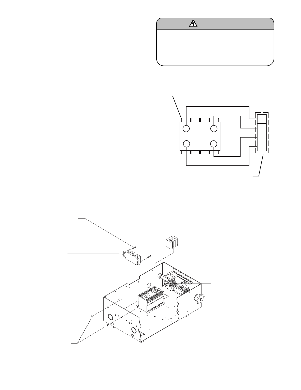
COMPONENT MOUNTING
COMPONENT MOUNTING
1. Disconnect power to operator.
2. Determine whether the auxiliary contact block is required
on the OPEN or CLOSED side of the contactor and snap
in place.
3. When present, fasten the terminal block down to the box
using the two #8-32 x 5/8" long self tapping screws
provided (Figure 2).
WIRING FOR MODIFICATION WITH WIRE LEADS
1. Connect ends of wire leads to desired field wiring with
wire nuts to complete installation (Figure 1).
2. Restore power to operator.
WIRING FOR MODIFICATION WITH TERMINAL
LEADS
1. Connect the wires from the auxiliary limit switch to the
new terminal block (Figure 1).
2. Restore power to operator.
FIGURE 1: AUXILIARY CONTACT BLOCK
FIGURE 2:
Auxiliary
Contact
Block
Terminal Block, 4 Pole
(when present)
To prevent possible SERIOUS INJURY or DEATH from
electrocution, disconnect electric power to operator
BEFORE installing.
ALL electrical connections MUST be made by a qualified
individual.
WARNING
53NO
54NO
LA1KN
11
WH
WH
61NC
62NC
WH
WH
11
12
13
14
 Loading...