

Page 1
To prevent possible SERIOUS INJURY or DEATH from
electrocution, disconnect electric power to operator BEFORE
installing.
ALL electrical connections MUST be made by a qualified
individual.
WARNING
APPLICATION REQUIREMENTS
This modification is available on both "logic" (L) and "contactor"
style (M) LiftMaster operators with 24V control circuits.
NOTE: Not available on model LGJ or with Hazardous Area
Modification.
FUNCTIONS
A 6-digit non-resettable 24VAC electro-mechanical counter is
mounted in the operator control enclosure. This counts the
number of times the CLOSE coil is energized on a contactor style
operator. When installed on a logic style operator, this will only
count the number of cycles when the door reaches the full open
position. If a mid-stop is programmed on a logic style operator,
this will not activate the counter.
WIRING
Refer to the wiring diagrams provided with the operator. Should
you need a replacement diagram or you are unsure of wiring
requirements, please call Technical Service at 1 (800) 528-2806.
INSTALLATION
Field modifications require the use of kit 71-90503000. A parts
bag for the “Logic” and “Contactor” style operators and a counter
will be provided with the field kit.
LOGIC 3 STANDARD AND DAMP ENVIRONMENT OPERATORS
1. Disconnect power from the operator. Verify that all LEDs are
OFF on the logic board.
2. Remove the parts from the bag labeled “Logic Parts.”
3. Using one of the crimp-on wire nuts, attach the 10" black wire
with the 0.187" quick connect to one of the black wires
coming from the counter.
4. Using the remaining crimp-on wire nut, attach the 10" black
wire with the 0.250" piggy-back quick connect to the
remaining black wire coming from the counter.
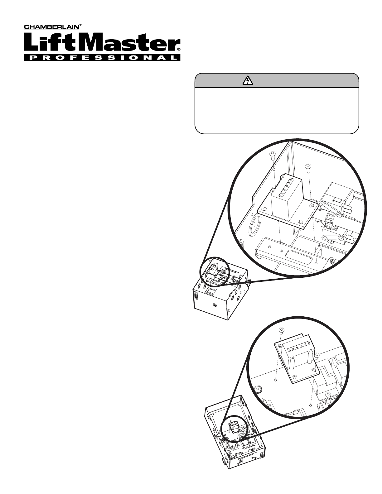
5. Locate the mounting position for the counter
(Figures 1 and 3). Using the (2) #8 screws (Model H electrical
box) or the (2) #6 screws (Model T or Damp Environment
electrical box), mount the counter in the electrical box making
sure that the wires are not pinched under the counter.
6. Locate the limit switch, plastic standoff for the limit switch,
(2) lockwashers, (1) metal nut plate, (1) metal back plate, and
(2) pan head 4-40 screws and install the limit switch above
the open limit switch (OLS) in the operator. Be careful to line
up the this limit switch with the OLS so that it will activate
just before the OLS activates.
7. Connect the 10" black wire with the 0.187" quick connect
(attached to the counter) to the common terminal of the limit
switch that was just installed.
8. Connect the 10" blue wire with the 0.187" quick connect and
0.250" piggy-back quick connect to the normally closed (NC)
terminal of the limit switch that was just installed.
NON-RESETTABLE COUNTER
90503000 and 71-90503000
FIGURE 1
Logic 3 Standard
Models T and GH
Logic 3 Standard
Models H and J Operators
Page 2
© 2006, The Chamberlain Group, Inc.
01-13401E All Rights Reserved
9. Remove both wires from the 24 Volt secondary of the
transformer, one yellow and one blue.
10. Attach the 0.250" quick connect of the blue wire (connected
to the NC terminal of the limit switch) to one of the bare
terminals on the 24V secondary of the transformer. Connect
blue wire removed in the previous step to the piggy-back
terminal of the wire.
11. Attach the 0.250" quick connect of the black wire (connected
to the counter) to the remaining bare terminal on the 24V
secondary of the transformer. Connect the yellow wire
previously removed from the transformer to the piggy-back
terminal of the wire.
12. Secure loose wires with cable ties.
13. Restore power to the operator. Verify normal operation.
CONTACTOR STYLE OPERATORS
1. Disconnect power from the operator. Verify that it is
inoperable.
2. Remove the parts from the bag labeled “Contactor Parts.”
3. Using the crimp-on wire nuts, attach each of the 20" black
wires to each of the black wires coming from the counter.
4. Using the (2) #8 screws, mount the counter to the electrical
box. Depending on the electrical box, it may be necessary to
drill one or more holes in the box to mount the counter
securely. Make sure that the wires are not pinched under the
counter.
5. Connect one of the black wires from the counter to the A1
terminal of the close side of the contactor.
6. Connect the remaining black wire from the counter to the A2
terminal of the close side of the contactor.
7. Secure loose wires with cable ties.
8. Restore power to the operator. Verify normal operation.
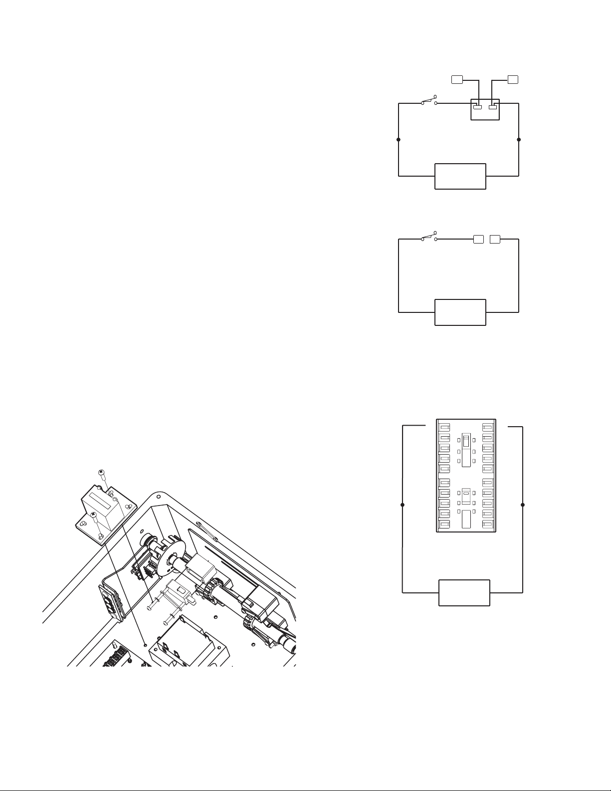
A1
A1
A2
A2
CLOSE
OPEN
(BK)
(BK)
Contactor
24VAC
Counter
(5va Max.)
CONTACTOR OPERATOR
CONTACTOR STYLE OPERATOR
FIGURE 2
FIGURE 3
Logic 3 Damp Environment
Models CT, CH, CJ, CGH and CGT
LOGIC STYLE OPERATORS
Terminals
on Logic Board 3
(BL)
13
(BK)
(BK)
C
Aux.
Open L/S
C
Aux.
Open L/S
NO
NC
NO
NC
(BL)
24VAC
Counter
(5va Max.)
LOGIC 3
24VAC
Counter
(5va Max.)
LOGIC 2
FMR
X
24VAC
12
Terminals
on Logic Board 2
dary
n
co
e
S
13
(YE)
14
(BL)
 Loading...