

Page 1
A UXILIARY LIMIT MODIFICATION
WARNING
(For Use With LGJ Operator)
90-14180
APPLICATION REQUIREMENTS:
This modification is available to model LGJ operators. Each switch, or pole, provides a means
to control auxiliary controls.
ARTS LIST
P
PART NUMBER
23-10041-1
27-10199
82-PX04-20
81-305
96-BL05-11
96-WH05-11
:
DESCRIPTION
DUAL LIMIT SWITCH ASSEMBLY
TIE WRAP, 5-1/2”
SCREW, #4-40 X 1-1/2” LONG PAN HD PHILLIPS
3/16” BLACK SHRINK TUBING
WIRE, 16GA. BLUE 5” STRIP X STRIP
WIRE, 16 GA. WHITE 5” STRIP X STRIP
INSTALLATION INSTRUCTIONS
1. Unplug the eight pin connector (white) from the circuit
board. Carefully remove the board from the four stands and
let it hang to one side by the remaining wires.
2. Disconnect the yellow transformer wire from the eight
pin connector by pressing the locking tab and pulling the
wire out.
3. There are three yellow wires in a wire nut, one of these
wires comes from the eight pin connector. Disconnect
these wires from the wire nut. At this point the eight pin
connector is only connected to the limits, this will allow the
complete limit switch assembly to be removed.
4. Remove all four screws that hold the limit switches in
place and return these screws to stock. Remove the
complete limit switch assembly: if necessary, cut any wire
ties that prevent the assembly from being removed.
5. The bottom limit switches (white switches) are the close
and open limit switches, these switches will not be
changed. Unsolder the wires from the top limit switches
(red/black switches), these are the auxiliary limit switches,.
as follows:
a. Locate the wire that runs from the common on the
close switch to the common on the auxiliary close
switch, unsolder the end connected to the auxiliary
closed switch.
b. Unsolder the yellow wire from the common on the
auxiliary close switch to the common on the auxiliary
open switch and set of to the side.
c. Unsolder the end of the orange wire that runs
to the normally closed on the auxiliary open switch.
d. Unsolder the end of the purple/white wire from the
normally closed on the auxiliary close switch.
QUANTITY
2
4
4
6”
3
3
WARNING
Disconnect power to the operator(s) before
proceeding with installation.
6. If the two auxiliary limit switches are not damaged return
them to stock. Install the two new dual switches in place of
the original auxiliary switches. If a fixture is not available it
may be necessary to connect the switches together to hold
everything steady for soldering. It might be easier to solder
some wires on before putting everything together. It will be
necessary to have everything together to resolder the
yellow wires removed in step 5.
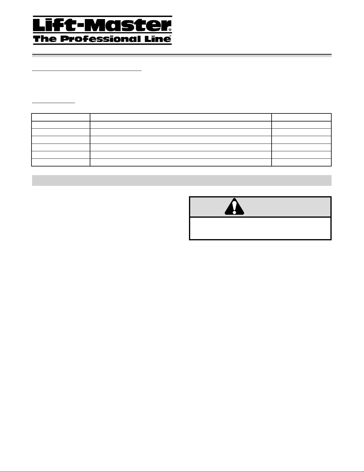
7. Please see figure 1 for the arrangement of the wires.
Remember to install shrink wrap tubing on all of the wires
on the normally closed (NC) and normally open (NO)
prongs of the switches. It is not necessary to insulate the
wires on the common (C) prongs.
9. Install the switch assembly back in the operator. Replace
any wire ties that had to be cut to remove the original
assembly. Reconnect the three yellow wires into the wire
nut. Reinstall the yellow transformer wire into the eight
position connector (see figure 2 for the exact location)
between the orange/black and the yellow wires.
10) Reinstall the circuit board and plug the eight position
connector back onto the board.
11) Run the operator and check continuity on the new
switches. Coil up the blue and white wires so the cover can
go back on. Supply diagram 04145.
Page 2
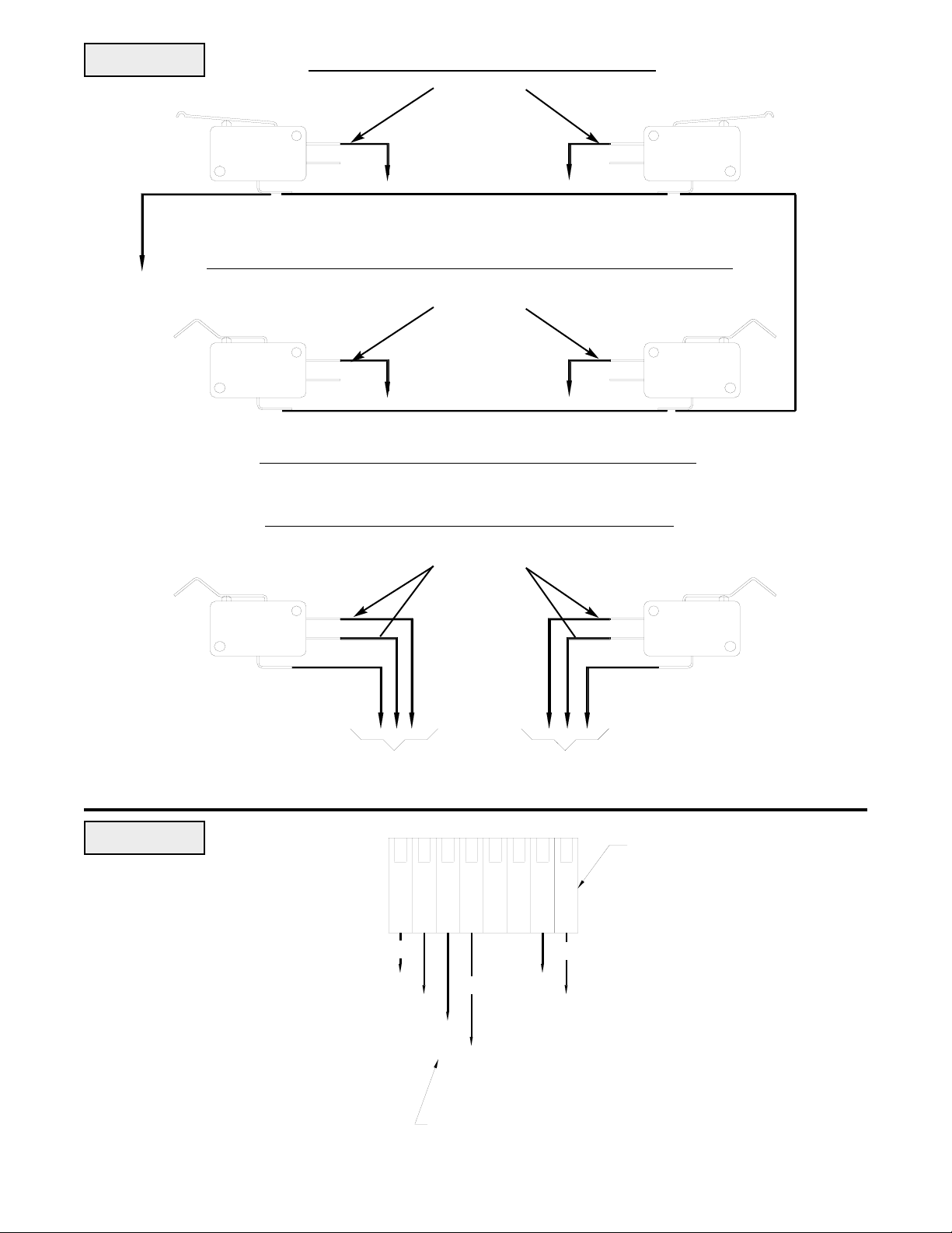
FIGURE 1
BOTT
OM SWITCHES (STAY THE SAME)
INSULATED
(YE)
OPEN
NC
NO
C
(OR/BK)
(YE) JUMPER
(RD)
NC
NO
CLOSE
C
CENTER SWITCHES (REPLACE ORIGINAL TOP SWITCHES)
INSULATED
AUX. (1)
OPEN
C
NC
NO
(OR)
(YE) JUMPER
(PU/WH)
NC
NO
AUX. (1)
CLOSE
C
NOTE: ALL WIRE ON ABOVE 4 SWITCHES ARE ORIGINAL
TOP SWITCHES (NEW AUXILIARY SWITCHES)
INSULATED
(YE)
JUMPER
FIGURE 2
AUX. (2)
OPEN
C
NC
NO
3 BLUE WIRES
(5” LONG)
(RD)
(OR/BK)
YELLOW
HEAVY
(YE)
3 WHITE WIRES
(5” LONG)
(OR)
(PU/WH)
NC
NO
AUX. (2)
CLOSE
C
8 POSITION CONNECTOR
ASSEMBLY
REMOVE THIS WIRE SO THAT THE LIMIT ASSEMBLY CAN BE REMOVED
01-14181A All Rights Reserved
© 1998, The Chamberlain Group, Inc.
 Loading...