

Page 1

100VA TRANSFORMER
CONVERSION INSTRUCTIONS
90-100OP
FUNCTIONS:
1. Upgrades the transformer in the operator enclosure from 40VA to 100VA
2. Provides additional control circuit power for the auxiliary equipment such as loop
detectors, gearbox heaters, electrical box heaters and other such devices.
SPECIFICATIONS:
1. For use with model T, GT, J, H, GH, SD and GSD operators.
2. If used in conjunction with other cont rol wiring modifications, space limitation in the
operator control enclosure may necessitate a separat e wall mounted enclosure for this
modification.
3. Not available with hazardous area modification..
PREPARATION:
Unpack kit to verify the parts listed below are included. Refer to installation inst ructions
on reverse side.
PACKING LIST
PART NUMBER
** 21-3240-1
* 21-3460-1
35-204
82-PX08-04T
95-BK06-26
** 95-BR11-66
* 95-BR31-16
95-YE08-16
** 95-WH12-66
XFMR 120/240V, 24V PRIMARY, 100VA SECONDARY
XFMR 240/460V, 24V PRIMARY, 100VA SECONDARY
FUSE 4AMP 125VAC
SCREW #6-32 X 1/2” LG. PAN HEAD PHILLIPS SELF TAPPING
WIRE 18GA., BLACK 6”, .110 FAST. X .250 FORK
WIRE 18GA., BROWN 11”, .250 FORK X .250 FORK
WIRE 18GA., BROWN 31”, STRIP X .250 FORK
WIRE 18GA., YELLOW 8”, STRIP X .250 FORK
WIRE 18GA, WHITE 12”, .250 FORK X .250 FORK
DESCRIPTION
QUANTITY
1
1
1
1
2
1
1
1
1
* Used on 1Ph Operators
**
Used on 3Ph Operators
Page 2
INSTALLATION INSTRUCTIONS 1PH OPERATORS
WARNING
8. Install fuse #35-204 into fuse clips on transformer.
WARNING
(See figure one for additional wiring help).
TO AVOID SERIOUS PERSONAL INJURY OR DEATH
FROM ELECTROCUTION, DISCONNECT ELECTRIC
POWER TO OPERATOR BEFORE INSTALLING
100VA TRANSFORMER.
115V 1Ph OPERATORS:
1. Remove the four wires connected to the 40VA
transformer in the electrical box and discard.
2. Remove the 40VA transformer from the electrical
box and replace with new 100VA transformer. Mount
the transformer with (4) #8-32 x 1/4” self tapping
screws (supplied).
3. Connect a jumper from H1 to H3 and from H2 to
H4 on the transformer. The jumpers are supplied
along with the transformer.
4. Connect a new black wire from H4 on the
transformer to #6 on th closed contactor.
5. Connect a new white wire from H1 on the
transformer to L2 on the terminal block.
230V 1Ph OPERATORS:
1. Remove the four wires connected to the 40VA
transformer in the electrical box and discard.
2. Remove the 40VA transformer from the electrical
box and replace with new 100VA transformer. Mount
the transformer with (4) #8-32 x 1/4” self tapping
screws (supplied).
3. Connect a jumper from H2 to H3 on the
transformer. The jumpers are supplied with the
transformer.
4. Connect a new black wire from H4 on the
transformer to #6 on th closed contactor.
5. Connect a new white wire from H1 on the
transformer to L2 on the terminal block.
6. Connect a new brown wire from X2 on the
transformer to the interlock switch.
7. Connect a new yellow wire from XF on the
transformer to the wire nut.
6. Connect a new brown wire from X2 on the
transformer to the interlock switch.
8. Install fuse #35-204 into fuse clips on transformer.
(See figure one for additional wiring help).
7. Connect a new yellow wire from XF on the
transformer to the wire nut.
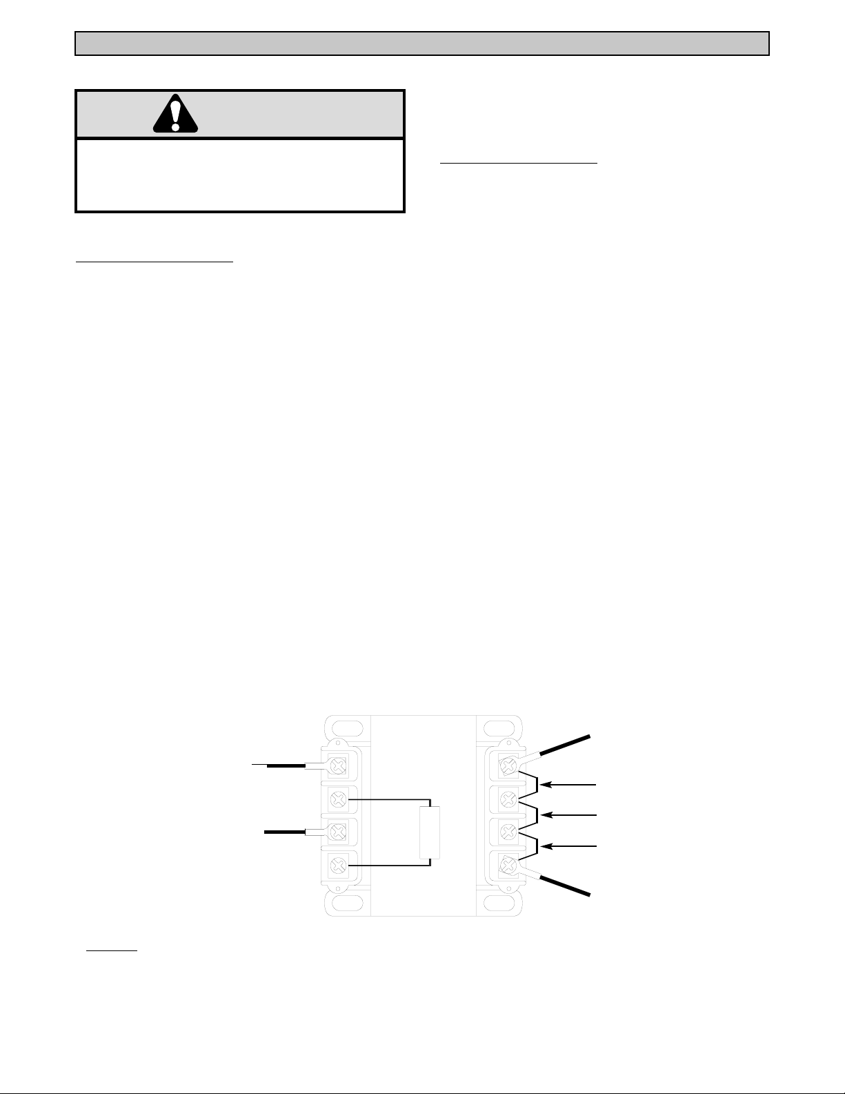
FIGURE 1
BK
INTERLOCK SWITCH
WIRE NUT
BR
YE
NOTES:
1. For 115V 1Ph operators connect a jumper between H1 and H3 and between H2 and H4.
2. For 230V 1Ph operators connect a jumper between H2 and H3.
3. Install fuse (#35-204) in mounting clips on transformer.
X2
XF
X1
H1
H3
H2
FUSE
H4
WH
#L2 TERMINAL BLOCK
JUMPER, 115V OPERATORS
JUMPER, 230V OPERATORS
JUMPER, 115V OPERATORS
#6 CLOSED CONTACTOR
2
Page 3

INSTALLATION INSTRUCTIONS 3PH OPERATORS
WARNING
8. Install fuse #35-204 into fuse clips on transformer.
WARNING
(See figure one for additional wiring help).
TO AVOID SERIOUS PERSONAL INJURY OR DEATH
FROM ELECTROCUTION, DISCONNECT ELECTRIC
POWER TO OPERATOR BEFORE INSTALLING
100VA TRANSFORMER.
230V 3Ph OPERATORS:
1. Remove the four wires connected to the 40VA
transformer in the electrical box and discard.
2. Remove the 40VA transformer from the electrical
box and replace with new 100VA transformer. Mount
the transformer with (4) #8-32 x 1/4” self tapping
screws (supplied).
3. Connect a jumper from H1 to H3 and from H2 to
H4 on the transformer. The jumpers are supplied
along with the transformer.
4. Connect a new black wire from H4 on the
transformer to #6 on the closed contactor.
5. Connect a new black wire from H1 on the
transformer to #2 on the closed contactor.
460V 3Ph OPERATORS:
1. Remove the four wires connected to the 40VA
transformer in the electrical box and discard.
2. Remove the 40VA transformer from the electrical
box and replace with new 100VA transformer. Mount
the transformer with (4) #8-32 x 1/4” self tapping
screws (supplied).
3. Connect a jumper from H2 to H3 on the
transformer. The jumpers are supplied with the
transformer.
4. Connect a new black wire from H4 on the
transformer to #6 on the closed contactor.
5. Connect a new black wire from H1 on the
transformer to #2 on the closed contactor.
6. Connect a new brown wire from X2 on the
transformer to the overload.
7. Connect a new yellow wire from XF on the
transformer to the wire nut.
6. Connect a new brown wire from X2 on the
transformer to the overload.
8. Install fuse #35-204 into fuse clips on transformer.
(See figure one for additional wiring help).
7. Connect a new yellow wire from XF on the
transformer to the wire nut.
FIGURE 1
BK
BR
OVERLOAD
YE
WIRE NUT
X2
-
XF
X1
NOTES:
1. For 230V 3Ph operators connect a jumper between H1 and H3 and between H2 and H4.
2. For 460V 3Ph operators connect a jumper between H2 and H3.
3. Install fuse (#35-204) in mounting clips on transformer.
H1
H3
H2
FUSE
H4
BK
#6 TERMINAL BLOCK
#2 CLOSED CONTACTOR
3
Page 4

01-12150B All Rights Reserved
© 1998, The Chamberlain Group, Inc.
 Loading...