

Page 1
OWNERS MANUAL
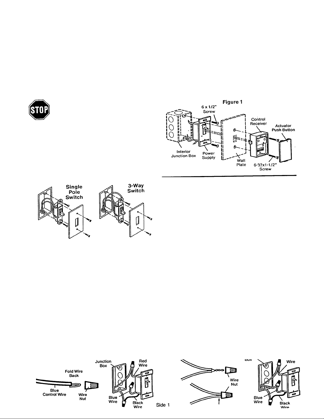
5. Pull switch from the junction box in order to access the connecting
terminals.
On 3-way switches, mark the common terminal wire before
disconnecting. (Common terminal may be marked "common",
"com" - or uses a different color screw (gold or silver) than the
other two terminal screws.)
Transmitter range will vary depending on your house and wiring construction. Metal lath, foil-backed insulation or aluminum siding will
reduce range. After installation is complete, test transmitter operation at various locations within your home for convenience and range.
SINGLE POLE SWITCH: If transmission range Is noticeably shorter when turning light OFF than when turning light ON, reverse wiring
connections.
Start by capping the black control wire to the COMMON "hot or live"
wire; the red and blue control wires separately to the other two junction
box wires in any order. Screw wire nuts on clockwise making sure bare
wires are covered.
SERIES 72
INDOOR/OUTDOOR WIRE-IN LIGHT CONTROL
FOR INSIDE USE ONLY WITH INCANDESCENT LAMP CIRCUITS OF 500 WATTS OR LESS. NOT FOR USE IN CIRCUITS WITH
FLUORESCENT LAMPS OR WITH LIGHT DIMMERS.
The Wire-in Control can be operated by any Series 50, 51, 52, 53 or Model 73 transmitter.
The Wire-in Control consists of two parts: the power supply and the receiver. It can replace either single pole (1 switch controlling a single light) or 3way switches (2 switches controlling a single light). Depending on the 3-way switch wiring, light may turn on after a power failure. If properly wired,
this will not occur with a single pole switch installation.
TURN OFF THE POWER TO CIRCUIT AT FUSE
BOX OR CIRCUIT BREAKER BEFORE BEGINNING INSTALLATION
Figure 1 illustrates the installation of receiver and power supply
to junction box in interior wall.
1. Pry up lower edge of actuator button until it separates from
receiver housing. Set actuator aside.
2. Remove the 6-32"x1-1/2" screw and unplug receiver from power
supply. Set receiver aside.
3. Remove wall plate and set aside for re-assembly.
4. Remove screws holding switch to junction box.
_________________________________________________________________________________________________________
6. Disconnect wires from switch. Straighten the ends and make sure
that insulation is trimmed back 1/2" to allow connection of power
supply wires.
_______________________________________________________________________________________________________
3-WAY SWITCH: It transmission range Is noticeably shorter when turning light OFF than when turning light ON, the Wire-in Control needs
to be installed in the other switching location. (The black wire in the Wire-in Control must be connected to the "hot" junction box wire.)
CAUTION: If there is a ground on your switch (usually a bare wire attached to a green screw on switch), connect wire to the metal junction
box. If box is plastic, connect wire to metal part of Wire-in Control.
_________________________________________________________________________________________________________
SINGLE POLE SWITCH 3-WAY SWITCH
Fold the BLUE power supply wire back as shown and cap with wire nut.
Screw nut in clockwise direction to secure.
Cap black control wire to one junction box wire and red conrol wire to the
other. Screw wire nuts on clockwise, making sure bare wires are covered.
Page 2
7. Carefully pack the wiring back into junction box. Make sure wires
Follow instructions packed with your multi function transmitter.
Remove the transmitter cover screw. Turn case over (push
button side up).
CAUTION: Be careful not to move circuit board
components.
CAUTION: TO AVOID ELECTRIC SHOCK,move the slide switch to
the OFF position whenever It is necessary to change a light bulb.
are not pinched or strained.
8. Fasten power supply to junction box with the #6x1-1/2" flat-head
screws provided.
9. Move power supply switch to the right. Move receiver slide bar so
"OFF" is visible. The control will be OFF.
10. Refer to Figure 1. Position wall plate over the junction box. Align
receiver so that three-pin plug engages holes in power supply and
slide bar engages the power supply switch. Insert (2) #6-32x1-1/2"
screws through fastening holes in receiver, wall plate and power
supply. Tighten securely.
Do not replace the actuator push button until you have set the
code. See instructions below.
POWER SUPPLY
RECEIVER
______________________________________________________________________________________________________
PROCEDURE FOR SETTING OR CHANGING THE CODE
The Wire-in Control receiver and transmiter must be set with matching
codes. To set (or change the code for any reason follow instructions
below.
The receiver code switches are located on the front of the unit, behind
the actuator. The switch code block with plus (+), (0) and minus(-)
positions provide 19,683 possible code settings.
Reassemble transmitter cover case. Snap the actuator cover onto
receiver. Turn on the power to circuit. Move receiver slide bar so
"ON" is visible. Control will be ON.
WITH MULTI FUNCTION TRANSMITTER
WITH SINGLE CHANNEL TRANSMITTER
Set (or change) code in receiver by sliding one or more of the 9 code
switches to a plus, (0) or minus position.
Hold transmitter circuit board alongside receiver code switch block. Set
code switches in transmitter to match positions of receiver code
switches.
Reassemble transmitter case. Snap actuator cover onto receiver. Turn
on the power to circuit. Move receiver slide bar so "ON" is visible. Control
will be ON.
________________________________________________________________________________________________________
11. TO TEST: press actuator push button. Light should turn on.
Press again, Light should turn off. Press transmitter push button.
Light should turn on. Press again and light should turn off.
NOTE: Allow a 1-second interval between transmitter
operations.
If light does not operate. check to be sure:
12.
• Power is ON. Check fuse box or circuit breaker.
• Light bulb is "good".
• Receiver is firmly connected to power supply and slide bar is in ON
position,
• Electrical wiring is correct. Review the wiring instructions on Side 1.
• Receiver and transmitter have matching code settings.
• You are pressing the transmitter push button selected to operate
Wire-in (on multi function transmitters).
• Transmitters battery has power. NOTE: Test light on the
transmitter should glow when push button is pressed.
(Battery changing information is included in instructions packed
with your transmitter).
IMPORTANT NOTE: If you use less than a 40 Watt bulb, the lamp
may glow dimly when OFF. This is normal.
If two or more Light Products are installed, they must be located at
least 10 feet apart to prevent electronic Interference.
__________________________________________________
There is a selection of accessories for use with the multi function
remote transmitter:
Series 53
Multifunction
Remote Transmitter
Series 74
Appliance Control
Receiver Module
Series 71
Indoor/Outdoor
Receiver Module
114A1056 Printed in Mexico
 Loading...