

Page 1
RED/GREEN LIGHT
MODIFICATION
FOR MODEL 71-REDGRN-HCT
FUNCTION
When the door is in motion, the timer circuit will activate
the red lamp holder and remain illuminated until door
reaches open or closed position. When the door reaches
the full open position, the timer circuit will activate the
green lamp holder and will remain illuminated based on
timer setting. When the door reaches the closed position,
the timer circuit will activate the red lamp holder and will
remain illuminated based on timer setting.
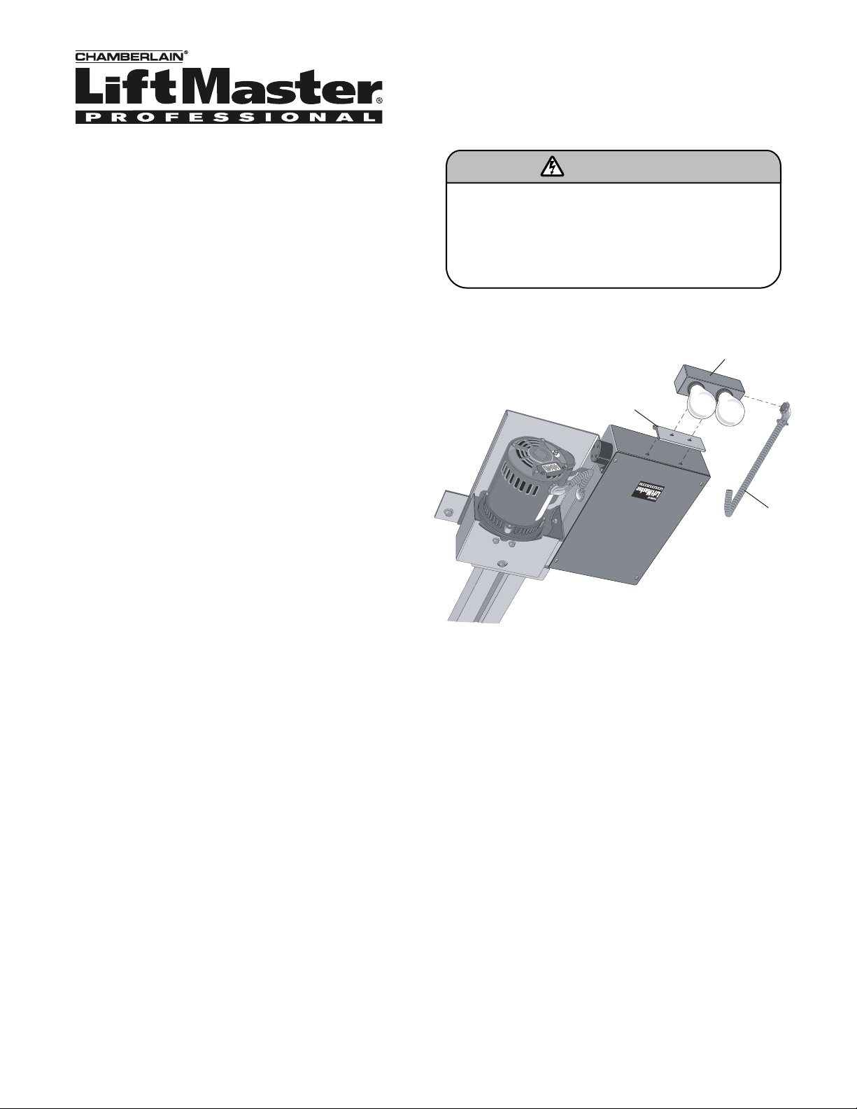
MOUNT THE LIGHT BOX
NOTE: If the operator requiring modification does not
contain required holes for light box mounting, it will be
necessary to add the holes. Use screws provided in kit for
mounting (Figure 1).
1. Disconnect power to the operator.
2. Attach the mounting bracket to the electrical box with the
self-tapping screws (2) provided.
3. Attach the light box assembly to the light box mounting
bracket. Secure in place with the self-tapping screws (2)
provided.
4. Connect conduit between light box assembly and
electrical box. Use the knockout hole shown on Figure 3.
NOTE: To avoid damage to relays, DO NOT EXCEED the
following:
• Red light - 75W, 120V incandescent bulb or 3A, 250Vac
(resistive load).
• Green light output - 75W, 120V incandescent bulb or 3A,
250Vac (resistive load).
• Conduit, wiring, and connectors should be sized and
installed per the national electric code.
To prevent possible SERIOUS INJURY or DEATH from
electrocution, disconnect electric power to operator
BEFORE installing.
ALL electrical connections MUST be made by a qualified
individual.
WARNING
Figure 1
Light Box
Mounting
Bracket
Conduit
Page 2
2
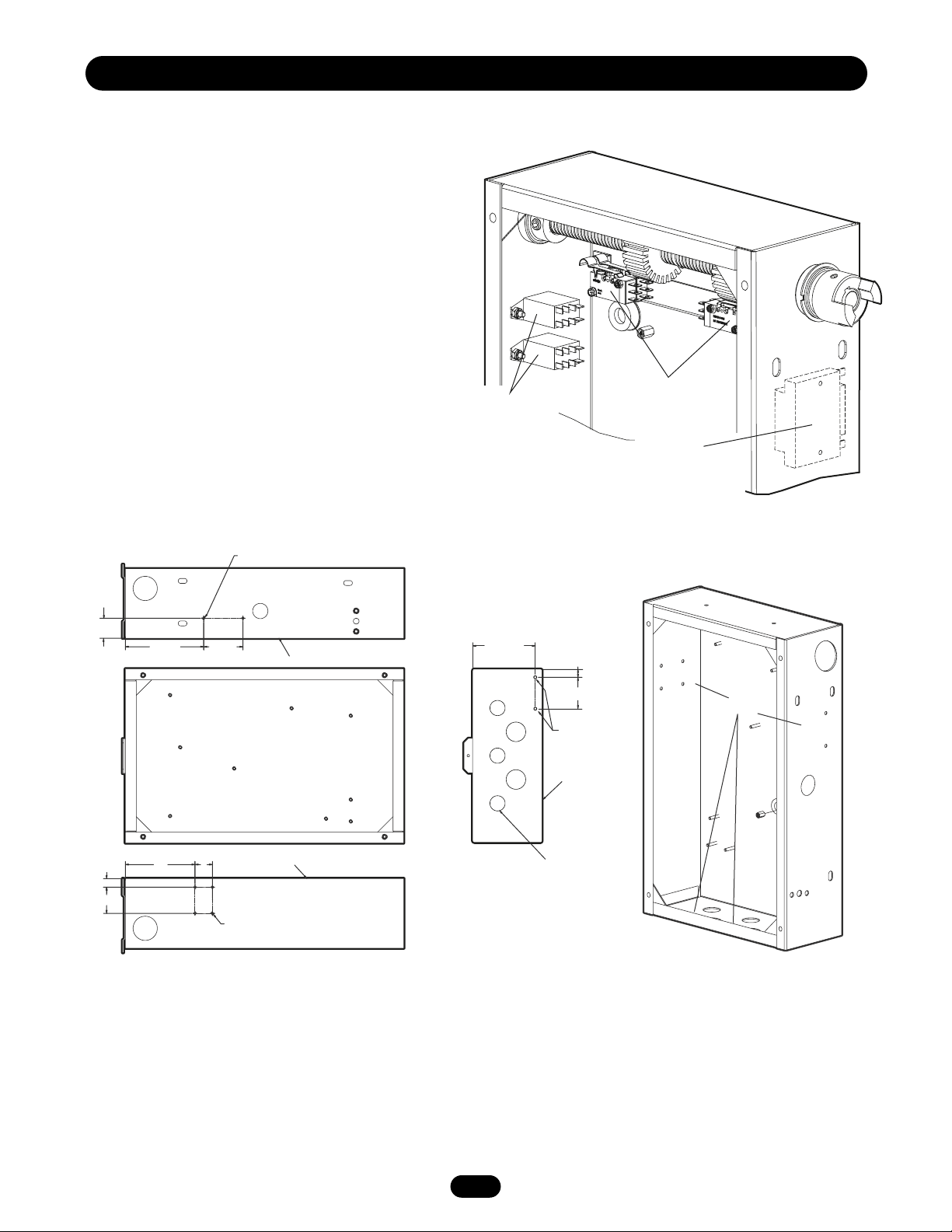
INSTALLATION
MOUNT COMPONENTS
NOTE: For additional component mounting reference, see
Figure 2.
If the operator requiring modification does not contain
required pem studs for component mounting, it will be
necessary to add holes. Use screws provided in kit for
mounting (Figure 3).
1. Mount timer on the pem studs in the electric box using
the locknuts (2) provided.
2. Mount the relay assembly on the pem studs in the
electric box using the locknuts (4) provided.
3. Mount the auxiliary limit switches using existing switch
hardware; note that the auxiliary limit switches are
mounted on top of the existing limit switches.
NOTE: If actuator on existing switches has been bent for
adjustment, it may be necessary to bend actuator arms on
new switches.
Relay
Assembly
Auxillary
Limit Switches
Timer
(Shown From
Outside Box)
Figure 2
Figure 3
0.15 Diameter
(#25 Drill Size)
1"
1/2"
1-1/2"
4-5/8"
4" 1"
2-1/4"
Top of Box
0.15 Diameter
(#25 Drill Size)
Top of Box
3-11/16"
1/2"
1.5"
(8) Holes
0.15 Diameter
(#25 Drill Size)
Top of Box
Knockout for Conduit
Page 3

WIRING CHART
3
WIRING DIAGRAM
WIRE CONNECTIONS FROM RELAY ASSEMBLY
NOTE: The following wires are provided from the factory
pre-wired to relay K1 & K2.
1. Connect red wire from relay (K1-7) to timer (T1).
2. Connect red wire from relay (K2-5) to timer (T2).
3. Connect grey wire from relay (K1-6) to auxiliary open
switch (NO).
4. Connect yellow wire from relay (K2-3) to auxiliary open
switch (NC).
5. Connect purple wire from relay (K2-8) to auxiliary close
switch (NO).
6. Connect white wire from relay (K1-1) to white wire
coming from red socket in light box with wire nut.
7. Connect white wire from relay (K1-2) to white wire
coming from green socket in light box with wire nut.
8. Connect grey wire from relay (K1-5) to auxiliary close
switch (NC).
9. Connect red wire from relay (K1-8) to 115 Vac input
power with wire nut.
10. Connect grey wire from relay (K2-7) to 115 Vac input
power with wire nut.
WIRE CONNECTIONS FOR LOOSE WIRES
NOTE: The following wires are provided from the factory in
the hardware bag.
1. Connect yellow wire from auxiliary open switch (COM)
NEUTRAL input with wire nut.
2. Connect yellow wire from auxiliary open switch (NC) to
auxiliary close switch (COM).
NOTE: The following wires are located in the light box assembly.
1. Confirm the white wires from light box have been wired
to the corresponding wires on the relay from above.
2. Connect red wire from light box to 115 Vac input power
with wire nut.
NOTE: This is an electrical diagram. It does not reflect
location of electrical components.
WIRING
LOOSE WIRES
WIRE DESCRIPTION CONNECTION TO BE MADE
Wire, 3" Yellow Aux. Open Aux. Close
3/16" Faston x 3/16" Faston Limit (NC) Limit (COM)
Wire, 28" Yellow Aux. Open Incoming
3/16" Faston x 1/4" Strip Limit (COM) Neutral
WIRE DESCRIPTION PREWIRED TO RELAY CONNECTION
Wire, 6" Grey 2 x 3/16" Faston K1-6 Aux. Open
Limit (NO)
Wire, 6" Grey 2 x 3/16" Faston K1-5 Aux. Close
Limit (NC)
Wire, 26" Grey K2-7 Incoming
3/16" Faston x 1/4" Strip 115 Vac
Wire, 26" White K1-1 White Wire
3/16" Faston x 1/4" Strip (Connected to
Red Socket)
Wire, 26" White K1-2 White Wire
3/16" Faston x 1/4" Strip (Connected to
Green Socket)
Wire, 6" Purple K2-8 Aux. Close
3/16" Faston x 3/16" Faston Limit (NO)
Wire, 10" Red K2-5 T2 Timer
3/16" Faston x 1/4" Faston
Wire, 10" Red K1-7 T1 Timer
3/16" Faston x 1/4" Faston
Wire, 26" Red K1-8 Incoming
3/16" Faston x 1/4" Strip 115 Vac
Wire, 6" Yellow 3/16" Faston K2-3 Aux. Open
with Spade x 3/16" Faston with Spade Limit (NC)
WIRE CONNECTIONS FROM RELAY ASSEMBLY
Auxiliary Closed
Limit Switch
NC
NO
COM
5
3
K2
Relay
GREY
K1
Relay
L1
L2
7
8
7
8
5
6
RED
1
2
4
6
3
1
2
4
GREY
PURPLE
WHITE
WHITE
YELLOW
YELLOW
GREY
YELLOW
Auxiliary Open
Limit Switch
NC
NO
COM
RED
RED
WHITE
(RED SOCKET)
WHITE
(GREEN SOCKET)
RED
T2
Timer
T1
Light Box
Page 4

© 2006, The Chamberlain Group, Inc.
01-32946C All Rights Reserved
HOW TO ORDER REPAIR PARTS
Our large service organization spans America.
Installation and service information are available.
Call our TOLL FREE number:
1-800-528-2806
www.liftmaster.com
TEST THE OPERATOR
1. Install red and green lights (not provided). Use 75 watt
maximum.
2. Set timer to desired delay for lights to remain on after
reaching open and closed position. Refer to relay label
for setting between 1-512 seconds.
3. Install cover and power up unit.
4. Test functionality based on the following:
a) When the door is in motion the timer circuit will
activate the red lamp holder and will remain
illuminated until door reaches open or closed position.
b) When the door reaches the full open position, the
timer circuit will activate the green lamp holder and
will remain illuminated based on timer setting.
c) When the door reaches the closed position, the timer
circuit will activate the red lamp holder and will remain
illuminated based on timer setting.
TESTING
 Loading...