

Page 1

OUTBO ARD BRAKE KIT
INSTRUCTIONS MANUAL
For Models: T, J and H
APPLICA
TION REQUIREMENTS:
This wiring modification is available to models T, J and H. Brake kit for all 115, 230/460
and 575V operators.
BRAKE FUNCTIONS:
Ensure your Brake Kit matches your operator and provides up to 5ft.-lb. of braking
torque @ 1725 RPM motor shaft. May be factory or field installed.
VOLTAGE REQUIREMENTS:
Models T and J
71-EB120 For operators with 115V incoming power source.
71-EB240 For operators with 230V and 460V incoming power source.
71-EB575 For operators with 575V incoming power source.
Model H
71-EB120H For operators with cable and 115V incoming power source.
71-EB240H For operators with cable and 230V and 460V incoming power source.
71-EB575H For operators with cable and 575V incoming power source.
INSTALLATION INSTRUCTIONS FOR OUTBOARD BRAKE KITS
NOTE: Refer to Brake illustration on page 3 and
Figure 1 on page 4 for additional help with
installation.
1. Locate the new Brake Mounting Bracket (item #4).
Mount the bracket to the motor studs in the same
position as the solenoid is to reside. Secure in place
with the (2) new flange nuts (item #20), select proper
thread to mate with motor studs.
2. Locate the (2) new Motor Standoffs (item #12).
Standoffs are threaded #10-32 on one end and #8-32
on the other, select the proper thread to mate with
motor studs. Mount the standoffs to the two
remaining motor studs, apply loctite to the motor
studs before installing.
3. Locate the new Brake Hub (item #14) and Push
Nut (item #23). Slide the new hub onto the shaft until
it lay against the motor pulley, secure in place with
the set screw and push nut supplied.
4. Locate the new Brake Mounting Plate (item #16)
and (2) new Collars (item #7). Install the collars into
the keyhole slots on the brake mounting plate (set
screws in collars to be located away from motor).
TO AVOID SERIOUS PERSONAL INJURY OR DEATH
FROM ELECTROCUTION, DISCONNECT ELECTRIC
POWER TO OPERATOR BEFORE INSTALLING.
5. Place Brake Assembly over motor shaft, align the
(2) Collars from step 4 with the (2) Standoffs from
step 2 and slide entire assembly into position on
Brake Hub (depress brake actuator lever to allow
rotation of brake disc for alignment).
6. Position Brake Assembly so that the edge of the
1.25 square extrusion in the Brake Disc (item #3) is
flush with the front of the Brake Hub. Secure in place
by installing (2) #10-32 screws and flat washers
through the (2) slots in Brake Mounting Plate, into the
(2) tapped holes in Brake Mounting Bracket and
tighten. Assure Assembly is square to motor and
tighten the (2) set screws (item #18), (1) in each
Collar.
Page 2
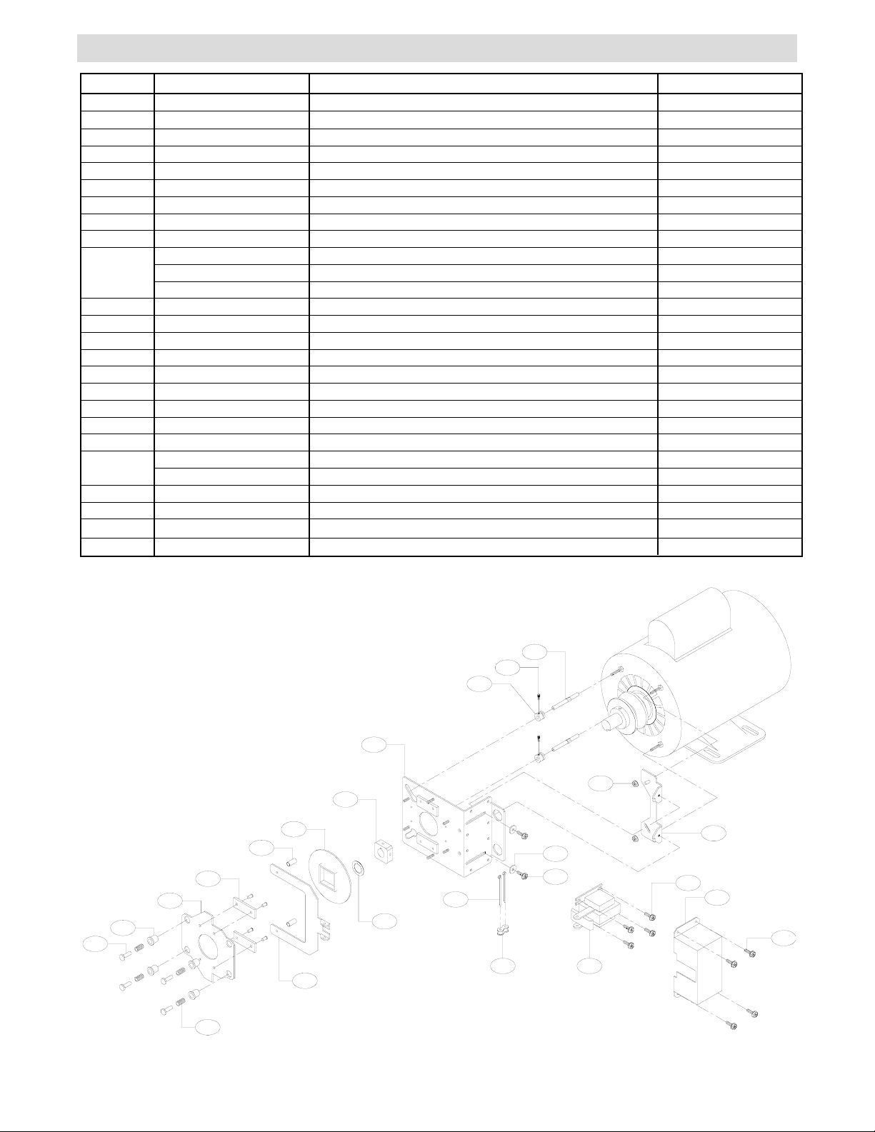
BRAKE KIT ILLUSTRATION
ITEM
1
2
3
4
5
6
7
8
9
*10
11
12
13
14
15
16
17
18
19
20
21
22
23
#24
PART NUMBER
10-10187
10-10190
10-10191
10-15039
11-10192
11-10193
12-14737
18-10194
19-48001
22-120
22-240
22-575
31-10186
31-15018
39-10182
75-10177
75-10184
75-15522
80-14414
82-SH06-03
82-WX10-08T
84-FN-08
84-FN-10
85-FW-10
86-CP04-112
87-P-062
75-11634
DESCRIPTION
BRAKE SOLENOID COVER
BRAKE RELEASE LEVER
BRAKE DISC
MOUNTING BRACKET, SUPPORT
SPRING CUP FOR BRAKE
BRAKE STUD
COLLAR, BRAKE ADJUSTMENT
SPRING, COMPRESSION
CHAIN,#48 X 1 PITCH
BRAKE SOLENOID 115V
BRAKE SOLENOID 230/460V
BRAKE SOLENOID 575V
SPACER,.20 I.D. X .31 O.D.
STANDOFF, BRAKE ASSEMBLY
BRAKE PAD
BRAKE HUB ASSY
BRAKE PRESSURE PLATE ASSEMBLY
BRAKE MOUNTING PLATE ASSEMBLY
KEY,3/16 X 3/16 X 2.0
SCREW, #6-32 X 3/16" SOCKET HEAD
SCREW, #10-32 X 5/8" FLANGE HEAD
NUT,#8-32 SERRATED FLANGE
NUT 10-32 SERRATED FLANGE
FLATWASHER #10
COTTERPIN 1/8" X 1-3/4" LONG
PUSH RING, 5/8"
BRAKE RELEASE CABLE ASSEMBLY
QUANTITY
1
1
1
1
4
4
2
4
1
1
1
1
2
2
2
1
1
1
1
2
10
2
2
2
2
1
1
* = Solenoid Shipped Depends on Operator Voltage
** = Flange Nuts used Depends on Motor Mounting Studs.
# = Shipped with Model “H” Operators (Refer to Page 4 for Instructions)
18
7
16
14
3
11
13
15
5
6
2
23
22
9
12
21
19
20
4
19
1
19
10
8
2
Page 3

WIRING INSTRUCTIONS FOR OUTBOARD BRAKE KITS
1. Disconnect the ends of wires running to the motor
and remove the conduit connector from the end of the
conduit, set off to the side for reinstallation.
2. Install the new double connector supplied to the
conduit where the connector was just removed in step
1. Reconnect the motor wires in the same manner as
they were removed in step 1.
3. Reinstall the conduit connector removed in step 1
to the new piece of conduit supplied.
MOTOR WIRING DIAGRAMS
ELECTRO MECHANICALSINGLE PHASE
3
1
P
8
BL
5
Y
2
4
GY
115V. CONNECTION
BL-BK
BL-BK
115V. BRAKE SOLENOID
4. Connect the (2) new blue/black wires supplied to
the brake solenoid. Feed the wires through the brake
mounting plate and then the conduit from step 4
(conduit connector side first). Secure the conduit
connector to the brake mounting plate.
5. Feed the brake wire through the new double
connector and secure the connector the conduit.
6. Wire the brake wires to the motor (refer to motor
wiring diagrams below). Secure the double connector
to the motor.
1
P
8
BL
5
Y
GY
2
4
230V. CONNECTION
BL-BK
3
BL-BK
230V. BRAKE SOLENOID
GY
BR
P
BR
Y
230V. CONNECTION
ELECTRO MECHANICALTHREE PHASE
J
J
BL-BK
OVERLOAD
BL-BK
(UP TO 3/4 HP)
575V. BRAKE SOLENOID
BL-BK
1
1
7
4
2
3
J
5
8
6
9
J
OVERLOAD
(UP TO 3/4 HP)
BL-BK
230V. BRAKE SOLENOID
GY
BR
P
BR
Y
2
7
8
936
460V. CONNECTION
BL-BK
4
J
5
J
OVERLOAD
(UP TO 3/4 HP)
BL-BK
460V. BRAKE SOLENOID
GY
BR
P
BR
Y
1
2
3
575V. CONNECTION
LOGIC CONTROL SINGLE PHASE
P
Y
BL
GY
1
8
5
4
115V. CONNECTION
BL-BK
BL-BK
115V. BRAKE SOLENOID
P
Y
GY
BL (Not Used)
1
5
4
230V. CONNECTION
BL-BK
BL-BK
230V. BRAKE SOLENOID
LOGIC CONTROL THREE PHASE
BL-BK
4
J
5
J
OVERLOAD
(UP TO 3/4 HP)
BL-BK
460V. BRAKE SOLENOID
GY
BR
P
BR
Y
230V. CONNECTION
BL-BK
1
1
7
4
2
3
J
5
8
6
9
J
OVERLOAD
(UP TO 3/4 HP)
BL-BK
230V. BRAKE SOLENOID
GY
BR
P
BR
Y
2
7
8
936
460V. CONNECTION
3
Page 4

RELEASE CABLE INSTALLATION INSTRUCTIONS
1. Locate the screw threads protruding through the
brake mounting plate opposite the brake solenoid.
Mount the new cable clamp supplied to the thread that is
second from the top and closest the motor and secure in
place with the #10 flange nut supplied.
2. Locate the release cable, cable sleeving and (2)
spring clamps. Install the two spring clamps onto one
end of the sleeving. Feed the release cable from the
side without the spring into the sleeving from the side
with the spring clamps.
3. Take the release cable assembly from above and
feed the release cable and sleeving through the cable
clamp installed in step 1, through the top hole of the
brake mounting bracket and brake mounting plate.
Once you get to the brake release lever feed only the
release cable through the top hole. Secure in place by
installing a #8 flatwasher and a 1/16” cable stop sleeve.
Secure cable stop sleeve in place by crimping down on it
with pliers (refer to detail 1).
DETAIL 1
#8 FLATWASHER
4. Locate the frame spacer that has the release chain
going through it. Take the end of the cable sleeving with
the two collars and slide it down into the notch in the
center of the bracket (be sure that one collar is on each
side of bracket). By releasing the collars, slide the
sleeving until there is at least 3” of sleeving protruding
out past the bracket. Secure in place by sliding the
collars as tight to the bracket as possible and snugging
up on the set screw (do not over tighten) refer to detail 2.
7. Pull release chain and release cable so that both are
taunt, being careful not to engage either of the two.
Connect the two together using the keyring on the end of
the spring.
TEST BRAKE RELEASE:
After the installation is complete pull the release chain to
insure the brake disengages. If the brake does not fully
disengage it can be adjusted by hooking the key ring
further away from the operator. Move the key ring one
chain link at a time, testing each time. Refer to drawing
below for additional help.
DETAIL 2
COLLAR W/SET SCREW
FIGURE 1
CABLE STOP SLEEVE
CABLE CLAMP
DETAIL 1
RELEASE CABLE
CABLE SLEEVING
CABLE SLEEVING
TO ADJUST TENSION ON BRAKE RELEASE, MOVE
KEYRING AWAY FROM OPERATOR ONE LINK AT A
TIME. BE SURE TO TEST AFTER EACH
ADJUSTMENT.
© 1999, The Chamberlain Group, Inc.
01-15519B All Rights Reserved
RELEASE CABLE
 Loading...