

Page 1
Life Fitness Model 9500HRT (REV 1 & 2) & 9500HR Stairclimber
How To... INSTALL THE LIFELINK UPGRADE KIT
TOOLS REQUIRED: Phillips Screwdriver, 5/32” Allen Head Wrench, 7/16” Open End Wrench , Pliers,
Wire Cutters, Anti-Static Strap
WARNING: FAILURE TO OBSERVE SAFETY PROCEDURES WHEN SERVICING THIS UNIT
COULD RESULT IN INJURY FROM ELECTRICAL SHOCK
STEP 1:
Turn the power off at the ON/OFF switch and disconnect the power cord from the wall outlet.
STEP 2:
With a 5/32” Allen wrench, loosen and remove the four housing screws on the lower right and left sides of the unit.
With a Phillips screwdriver, loosen and remove the four screws securing the grease tray to thebottom front of the
shroud. Carefully slide the housing up the column until you can rest the housing on the chassis bolts pre-installed in
the frame allowing the shroud to be held out of the way for the rest of the installation.
STEP 3:
Ground yourself by positioning an anti-static strap around your wrist and attaching the other end (alligator clip or
adhesive end) to a bare metal surface on the machine frame.
STEP 4:
Using a Phillips screwdriver, loosen and remove the four screws securing the DISPLAY CONSOLE to the support
bracket.
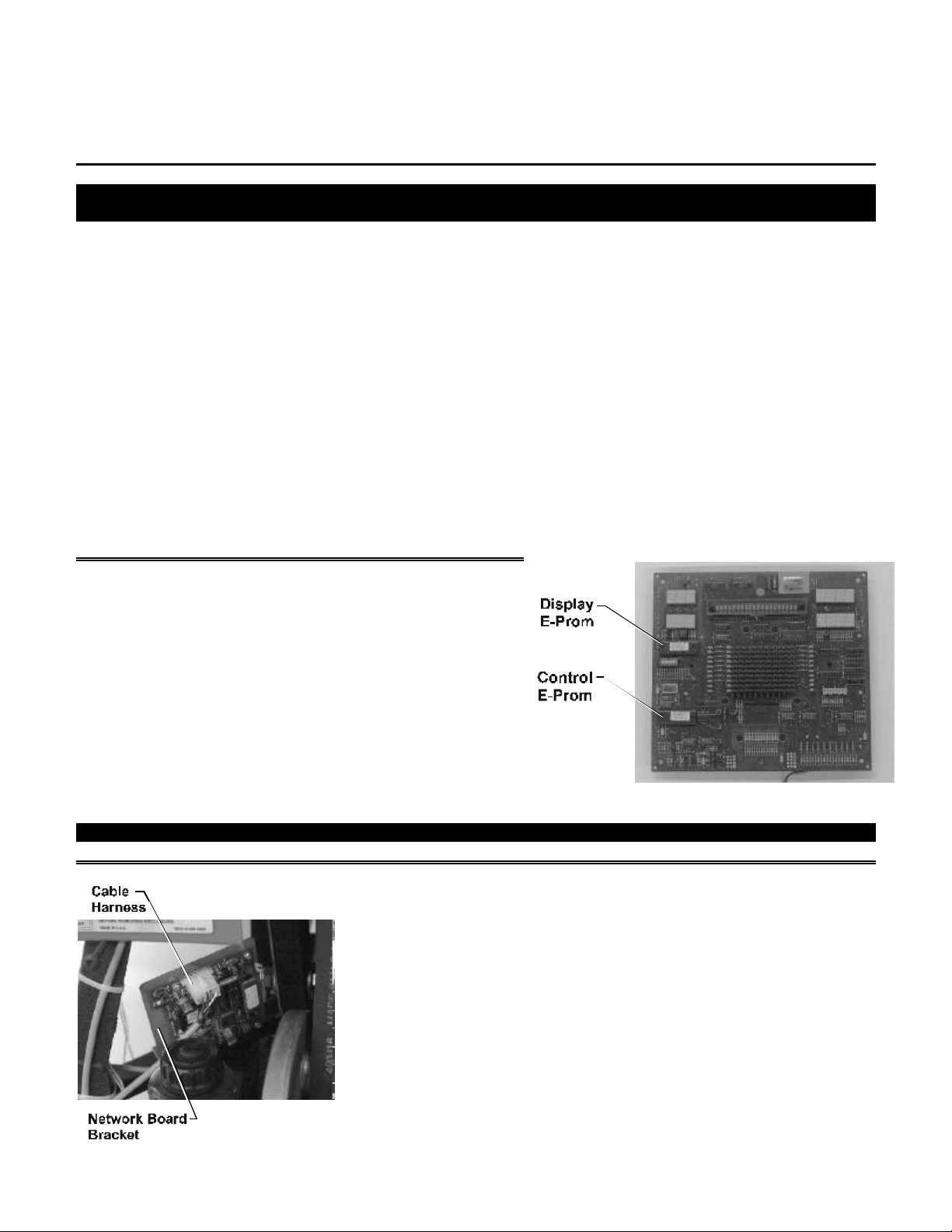
(9500HR & 9500HRT (REV 1) ONLY)
Disconnect the two wire harnesses from the DISPLAY
CONSOLE. Remove the six screws securing the back cover to
the faceplate. Remove the five screws securing the ELECTRONIC
BOARD to the faceplate and disconnect the RIBBON CABLE.
(NOTE THE ORIENTATION OF E-PROMS BY THE U-NOTCH
AND THE LABEL MARKINGS “DISPLAY” AND “CONTROL”)
Remove and replace the “DISPLAY” and “CONTROL” E-proms
with the E-proms supplied in the upgrade kit. Return the
ELECTRONIC BOARD to the faceplate and reconnect the
RIBBON CABLE. Return the back cover onto the faceplate and
set the DISPLAY CONSOLE aside untill later in this procedure.
NOTE: DO NOT REMOUNT THE DISPLAY AT THIS TIME!
STEP 5:
Lower the user right pedal arm to its lowest position. Remove the bolt holding
the user right tex-pak with a 5/32” hex head wrench and a 7/16” open end
wrench. Locate the hole NETWORK BOARD BRACKET mounting hole on the
FRAME at the user right side tex-pak mounting hole. Ensure that the bracket
is facing the rear of the machine and the connector is facing down (as
shown). Reinsert and tighten the bolt and nut to secure the tex-pak and
NETWORK BOARD BRACKET to the frame.
STEP 6:
Attach the 4-PIN connector located on the cable harness supplied in the
upgrade kit to the 4-PIN connector leading from the DISPLAY CONSOLE.
Route the remaining length of the cable harness down through the
monocolumn and plug it into the NETWORK BOARD. Return the two
remaining connectors to their proper locations on the DISPLAY CONSOLE.
Continued
Page 2

Remount the DISPLAY CONSOLE to the support bracket.
Page 3

Life Fitness Model 9500HR & 9500HRT (REV 1 & 2) Stairclimber
How To... INSTALL THE LIFELINK UPGRADE KIT
STEP 7:
Using the hex key wrench supplied in the upgrade kit and a pair of pliers,
remove the small metal cover to the left of the power module located in the
lower rear portion of the unit.
STEP 8:
Connect the STUB CABLE supplied in the upgrade kit to the NETWORK
BOARD and route it through the access hole created in Step 7. Place the
grommet supplied in the upgrade kit into the hole to prevent the STUB
CABLE from being pinched. Strain relief the cable to the FRAME away from
moving parts. Connect the other end of the STUB CABLE into the t-connector
on the backbone. Place the plastic plug supplied in the upgrade kit into the
remaining, unused hole.
STEP 9:
Reverse Steps 1 and 2 to return all remaining parts to their proper positions. Replace the power cord into the wall
outlet and turn the unit on at the ON/OFF switch. A blue box will appear on the LIFECENTER SCREEN stating
“INSTALLING NODE” and will disappear in approximately 30 seconds.
NOTE: DO NOT TURN OFF THE POWER OR DISCONNECT THE NETWORK DURING THIS TIME. DOING SO
BEFORE THE “INSTALLING NODE” MESSAGE DISAPPEARS MAY DEACTIVATE THE NETWORK BOARD.
Page 4

Should you require any assistance with this Technical Information, please direct all inquiries to:
Customer Support Services
10601 West Belmont Avenue
Franklin Park, IL 60131
(800) 351-3737 or (847) 451-0036 / FAX (847) 451-4137
MO51-00K23-A019
 Loading...